EP4365374A1 - Work vehicle - Google Patents
Work vehicle Download PDFInfo
- Publication number
- EP4365374A1 EP4365374A1 EP22832534.6A EP22832534A EP4365374A1 EP 4365374 A1 EP4365374 A1 EP 4365374A1 EP 22832534 A EP22832534 A EP 22832534A EP 4365374 A1 EP4365374 A1 EP 4365374A1
- Authority
- EP
- European Patent Office
- Prior art keywords
- lamp
- fixing portion
- storage position
- vehicle body
- furthermore
- Prior art date
- Legal status (The legal status is an assumption and is not a legal conclusion. Google has not performed a legal analysis and makes no representation as to the accuracy of the status listed.)
- Pending
Links
- 230000007246 mechanism Effects 0.000 claims description 29
- 230000002452 interceptive effect Effects 0.000 abstract description 8
- 238000003780 insertion Methods 0.000 description 14
- 230000037431 insertion Effects 0.000 description 14
- 230000005540 biological transmission Effects 0.000 description 7
- 238000000034 method Methods 0.000 description 5
- 230000000694 effects Effects 0.000 description 3
- 230000004048 modification Effects 0.000 description 2
- 238000012986 modification Methods 0.000 description 2
- 230000006835 compression Effects 0.000 description 1
- 238000007906 compression Methods 0.000 description 1
- 238000010276 construction Methods 0.000 description 1
- 238000004519 manufacturing process Methods 0.000 description 1
- 239000000463 material Substances 0.000 description 1
- 239000011435 rock Substances 0.000 description 1
Images






Classifications
-
- B—PERFORMING OPERATIONS; TRANSPORTING
- B60—VEHICLES IN GENERAL
- B60Q—ARRANGEMENT OF SIGNALLING OR LIGHTING DEVICES, THE MOUNTING OR SUPPORTING THEREOF OR CIRCUITS THEREFOR, FOR VEHICLES IN GENERAL
- B60Q1/00—Arrangement of optical signalling or lighting devices, the mounting or supporting thereof or circuits therefor
- B60Q1/02—Arrangement of optical signalling or lighting devices, the mounting or supporting thereof or circuits therefor the devices being primarily intended to illuminate the way ahead or to illuminate other areas of way or environments
- B60Q1/04—Arrangement of optical signalling or lighting devices, the mounting or supporting thereof or circuits therefor the devices being primarily intended to illuminate the way ahead or to illuminate other areas of way or environments the devices being headlights
- B60Q1/0483—Arrangement of optical signalling or lighting devices, the mounting or supporting thereof or circuits therefor the devices being primarily intended to illuminate the way ahead or to illuminate other areas of way or environments the devices being headlights mounted on a bracket, e.g. details concerning the mouting of the lamps on the vehicle body
-
- B—PERFORMING OPERATIONS; TRANSPORTING
- B60—VEHICLES IN GENERAL
- B60Q—ARRANGEMENT OF SIGNALLING OR LIGHTING DEVICES, THE MOUNTING OR SUPPORTING THEREOF OR CIRCUITS THEREFOR, FOR VEHICLES IN GENERAL
- B60Q1/00—Arrangement of optical signalling or lighting devices, the mounting or supporting thereof or circuits therefor
- B60Q1/02—Arrangement of optical signalling or lighting devices, the mounting or supporting thereof or circuits therefor the devices being primarily intended to illuminate the way ahead or to illuminate other areas of way or environments
- B60Q1/04—Arrangement of optical signalling or lighting devices, the mounting or supporting thereof or circuits therefor the devices being primarily intended to illuminate the way ahead or to illuminate other areas of way or environments the devices being headlights
- B60Q1/05—Arrangement of optical signalling or lighting devices, the mounting or supporting thereof or circuits therefor the devices being primarily intended to illuminate the way ahead or to illuminate other areas of way or environments the devices being headlights retractable
-
- B—PERFORMING OPERATIONS; TRANSPORTING
- B60—VEHICLES IN GENERAL
- B60Q—ARRANGEMENT OF SIGNALLING OR LIGHTING DEVICES, THE MOUNTING OR SUPPORTING THEREOF OR CIRCUITS THEREFOR, FOR VEHICLES IN GENERAL
- B60Q1/00—Arrangement of optical signalling or lighting devices, the mounting or supporting thereof or circuits therefor
- B60Q1/26—Arrangement of optical signalling or lighting devices, the mounting or supporting thereof or circuits therefor the devices being primarily intended to indicate the vehicle, or parts thereof, or to give signals, to other traffic
- B60Q1/2692—Arrangement of optical signalling or lighting devices, the mounting or supporting thereof or circuits therefor the devices being primarily intended to indicate the vehicle, or parts thereof, or to give signals, to other traffic retractable lights
-
- B—PERFORMING OPERATIONS; TRANSPORTING
- B60—VEHICLES IN GENERAL
- B60Q—ARRANGEMENT OF SIGNALLING OR LIGHTING DEVICES, THE MOUNTING OR SUPPORTING THEREOF OR CIRCUITS THEREFOR, FOR VEHICLES IN GENERAL
- B60Q1/00—Arrangement of optical signalling or lighting devices, the mounting or supporting thereof or circuits therefor
- B60Q1/26—Arrangement of optical signalling or lighting devices, the mounting or supporting thereof or circuits therefor the devices being primarily intended to indicate the vehicle, or parts thereof, or to give signals, to other traffic
- B60Q1/32—Arrangement of optical signalling or lighting devices, the mounting or supporting thereof or circuits therefor the devices being primarily intended to indicate the vehicle, or parts thereof, or to give signals, to other traffic for indicating vehicle sides, e.g. clearance lights
-
- B—PERFORMING OPERATIONS; TRANSPORTING
- B60—VEHICLES IN GENERAL
- B60Q—ARRANGEMENT OF SIGNALLING OR LIGHTING DEVICES, THE MOUNTING OR SUPPORTING THEREOF OR CIRCUITS THEREFOR, FOR VEHICLES IN GENERAL
- B60Q1/00—Arrangement of optical signalling or lighting devices, the mounting or supporting thereof or circuits therefor
- B60Q1/26—Arrangement of optical signalling or lighting devices, the mounting or supporting thereof or circuits therefor the devices being primarily intended to indicate the vehicle, or parts thereof, or to give signals, to other traffic
- B60Q1/2661—Arrangement of optical signalling or lighting devices, the mounting or supporting thereof or circuits therefor the devices being primarily intended to indicate the vehicle, or parts thereof, or to give signals, to other traffic mounted on parts having other functions
-
- B—PERFORMING OPERATIONS; TRANSPORTING
- B60—VEHICLES IN GENERAL
- B60Q—ARRANGEMENT OF SIGNALLING OR LIGHTING DEVICES, THE MOUNTING OR SUPPORTING THEREOF OR CIRCUITS THEREFOR, FOR VEHICLES IN GENERAL
- B60Q1/00—Arrangement of optical signalling or lighting devices, the mounting or supporting thereof or circuits therefor
- B60Q1/26—Arrangement of optical signalling or lighting devices, the mounting or supporting thereof or circuits therefor the devices being primarily intended to indicate the vehicle, or parts thereof, or to give signals, to other traffic
- B60Q1/34—Arrangement of optical signalling or lighting devices, the mounting or supporting thereof or circuits therefor the devices being primarily intended to indicate the vehicle, or parts thereof, or to give signals, to other traffic for indicating change of drive direction
- B60Q1/38—Arrangement of optical signalling or lighting devices, the mounting or supporting thereof or circuits therefor the devices being primarily intended to indicate the vehicle, or parts thereof, or to give signals, to other traffic for indicating change of drive direction using immovably-mounted light sources, e.g. fixed flashing lamps
-
- B—PERFORMING OPERATIONS; TRANSPORTING
- B60—VEHICLES IN GENERAL
- B60Q—ARRANGEMENT OF SIGNALLING OR LIGHTING DEVICES, THE MOUNTING OR SUPPORTING THEREOF OR CIRCUITS THEREFOR, FOR VEHICLES IN GENERAL
- B60Q2800/00—Features related to particular types of vehicles not otherwise provided for
- B60Q2800/20—Utility vehicles, e.g. for agriculture, construction work
-
- B—PERFORMING OPERATIONS; TRANSPORTING
- B62—LAND VEHICLES FOR TRAVELLING OTHERWISE THAN ON RAILS
- B62D—MOTOR VEHICLES; TRAILERS
- B62D49/00—Tractors
- B62D49/06—Tractors adapted for multi-purpose use
Definitions
- the present invention relates to a technique of a working vehicle including a lamp.
- JP 2017-19454 A discloses such a technique.
- JP 2017-19454 A discloses a working vehicle in which a combination lamp arm is provided so as to protrude laterally from left and right front pillars of a cabin, and a lamp (blinker and work lamp) is attached to a distal end of the combination lamp arm.
- a lamp blink and work lamp
- JP 2017-19454 A it is possible to reduce the manufacturing cost by attaching a plurality of types of lamps (blinkers and work lamps) to a common member (combination lamp arm).
- One aspect of the present disclosure has been made in view of the above circumstances, and an object of the present disclosure is to provide a working vehicle capable of preventing a lamp from interfering with surrounding crops, obstacles, and the like.
- a working vehicle includes: a fixing portion to which a lamp is fixed; and a support portion that supports the fixing portion and is capable of switching a position of the fixing portion between a use position where at least a part of the lamp is located on an outer side of a vehicle body with respect to a fender and a storage position where the lamp is located on an inner side of the vehicle body with respect to the fender.
- the support portion supports the fixing portion such that an irradiation surface of the lamp faces an inside of the vehicle body in a state where the fixing portion is switched to the storage position.
- the fixing portion includes a flat plate portion formed in a flat plate shape and fixed to a surface of the lamp on a side opposite to the irradiation surface.
- the lamp is disposed on a front side of the vehicle body with respect to a step for an operator to board, and the supporting portion switches to the storage position by rotating the fixing portion at the use position forward.
- the support portion is provided in a safety frame disposed on a front side of the vehicle body with respect to the step.
- the support portion supports the fixing portion such that at least a part of the lamp is located on an inner side of the vehicle body with respect to the safety frame in a state where the fixing portion is switched to the storage position.
- the working vehicle further includes a wiring connected to the lamp and disposed so as to pass through an inside of the vehicle body of the safety frame.
- the support portion supports the fixing portion such that an irradiation surface of the lamp faces an outside of the vehicle body in a state where the fixing portion is switched to the storage position.
- the support portion switches to the storage position by rotating the fixing portion at the use position rearward.
- the working vehicle further includes a holding mechanism capable of holding the fixing portion at the use position or the storage position.
- the lamp fixing portion
- the storage position by switching the position of the lamp (fixing portion) to the storage position, it is possible to prevent the lamp from interfering with surrounding crops, obstacles, and the like. As a result, it is possible to work in a narrow place. Furthermore, it is possible to suppress damage to the crop and damage to the lamp.
- the irradiation surface of the lamp faces the inside of the vehicle body at the storage position, it is possible to effectively suppress damage to the lamp (in particular, the irradiation surface).
- the lamp can be protected from the outside by the flat plate portion (fixing portion) at the storage position, and damage to the lamp can be effectively suppressed.
- the lamp in a case where the lamp is switched to the storage position, the lamp can be prevented from hindering the operator by being rotated in a direction away from the step (forward).
- the lamp can be firmly supported.
- At least a part of the lamp is located inside the vehicle body with respect to the safety frame at the storage position, so that it is possible to effectively suppress damage to the lamp.
- the irradiation surface of the lamp faces the outside of the vehicle body at the storage position, it is possible to effectively suppress damage to a back surface of the lamp.
- interference with surrounding crops, obstacles, and the like can be suppressed by housing the fixing portion (lamp) behind.
- the lamp (fixing portion) can be stably held at a predetermined position (the use position and the storage position).
- directions indicated by arrows U, D, F, B, L, and R in the drawings are defined as an upward direction, a downward direction, a forward direction, a backward direction, a left direction, and a right direction, respectively.
- the tractor 1 mainly includes a body frame 2, front wheels 3, a transmission device 4, rear wheels 5, a fender 6, an engine 7, a bonnet 8, a driving operation unit 9, a front safety frame 14, a rear safety frame 15, lamps 16, wiring 17, and a support mechanism 100.
- the body frame 2 is disposed with its longitudinal direction oriented in a front-rear direction.
- a front portion of the body frame 2 is supported by the pair of left and right front wheels 3.
- the transmission device 4 is provided at a rear portion of the body frame 2.
- a rear portion of the transmission device 4 is supported by the pair of left and right rear wheels 5.
- the rear wheel 5 is covered upward and forward by a pair of the left and right fenders 6.
- the engine 7 is provided in a front-rear middle portion of the body frame 2.
- the engine 7 is covered with the bonnet 8.
- the driving operation unit 9 for an operator to drive the tractor 1 is provided behind the engine 7.
- the driving operation unit 9 is provided with a step 10, a steering post 11, a clutch pedal 12, a seat 13, and the like.
- the step 10 forms a floor surface for an operator to board.
- An auxiliary step 10a for assisting the operator to board the step 10 is provided on a side of the step 10.
- the steering post 11 is provided at a front portion of the driving operation unit 9.
- a steering wheel 11a for steering the tractor 1 is provided above the steering post 11.
- the clutch pedal 12 for operating a clutch mechanism (not illustrated) of the tractor 1 is provided in front of the step 10 (on the left side of the steering post 11). Furthermore, although not illustrated, various other operation pedals (accelerator pedal, brake pedal, etc.) are provided in the step 10.
- the seat 13 on which an operator sits is provided at a rear portion of the driving operation unit 9.
- the front safety frame 14 and the rear safety frame 15 for protecting an operator on board the driving operation unit 9 are provided in front of and behind the driving operation unit 9.
- the front safety frame 14 is provided in front of the driving operation unit 9.
- the front safety frame 14 includes a lower frame 14a fixed to a rear portion of the body frame 2, and an upper frame 14b provided so as to be able to rock forward and backward with respect to the lower frame 14a.
- the rear safety frame 15 is provided behind the driving operation unit 9.
- Each of the lamps 16 is a lighting fixture capable of emitting light as necessary.
- the lamp 16 according to the present embodiment is a lighting fixture (so-called combination lamp) that can be used for a plurality of applications (direction indicators and vehicle width lights).
- the lamp 16 mainly includes a lamp housing 16a and a translucent cover 16b (see Figs. 3 and 4 ).
- the lamp housing 16a is a member provided with a light emitter (such as a light bulb) that emits light.
- the translucent cover 16b is a member that covers the light emitter provided in the lamp housing 16a. Light from the light emitter passes through the translucent cover 16b and is emitted to the outside. That is, a surface of the lamp 16 on the side where the translucent cover 16b is provided (for example, in Fig. 3(a) , a front side surface of the lamp 16) serves as an irradiation surface that irradiates the outside with light.
- the wiring 17 for supplying power and transmitting a control signal is connected to a back surface (surface opposite to the irradiation surface) of the lamp 16 (lamp housing 16a) (see Fig. 4 ).
- the lamps 16 are disposed on the left and right sides of the bonnet 8 in front of the driving operation unit 9. Each of the lamps 16 is provided on the front safety frame 14 (more specifically, the lower frame 14a) through the support mechanism 100.
- the power of the engine 7 is shifted in speed by the transmission device 4 and then transmitted to the front wheels 3 and the rear wheels 5 through an appropriate power transmission mechanism.
- the front wheels 3 and the rear wheels 5 are rotationally driven by the power of the engine 7, and the tractor 1 travels.
- the steering wheel 11a can adjust (change) a turning angle of the pair of right and left front wheels 3 and 3 according to a turning operation amount to steer the tractor 1.
- the configuration of the support mechanism 100 will be described mainly with reference to Figs. 4 and 5 .
- the support mechanisms 100 are provided on the left and right sides of a vehicle body of the tractor 1, the left and right support mechanisms 100 are bilaterally symmetric. Therefore, the description below focuses on the left support mechanism 100.
- the support mechanism 100 is for supporting the lamp 16.
- the support mechanism 100 can switch a position of a fixing portion 130 (in turn, the lamp 16) to be described later between a use position (See Figs. 3 and 9(a) ) where at least a part of the lamp 16 is located on an outer side of the vehicle body than the fender 6 in the left-right direction and a storage position (See Figs. 8 and 9(b) ) where the lamp 16 is located on an inner side of the vehicle body than the fender 6.
- Figs. 1 to 5 illustrate a state in which the fixing portion 130 is switched to the use position.
- the support mechanism 100 mainly includes a support portion 110, a vibration proofing member 120, the fixing portion 130, and a holding mechanism 140.
- the support portion 110 illustrated in Figs. 4 and 5 supports the lamp 16 through the fixing portion 130 to be described later.
- the support portion 110 mainly includes a first flat plate portion 111 and an insertion portion 112.
- the first flat plate portion 111 is a portion formed in a flat plate shape with a plate surface facing left and right.
- the first flat plate portion 111 is formed in an L shape in a side view including a portion extending upward and downward and a portion protruding forward from a lower portion thereof.
- the insertion portion 112 is a portion formed in a columnar shape with an axial direction facing up and down. A lower end portion of the insertion portion 112 is fixed to a front lower portion of the first flat plate portion 111. Thus, the insertion portion 112 is disposed so as to protrude upward from the front lower portion of the first flat plate portion 111.
- the vibration proofing member 120 is a member for suppressing transmission of vibration from the vehicle body of the tractor 1 to the lamp 16.
- the vibration proofing member 120 is formed in a rectangular plate shape.
- the vibration proofing member 120 is made of a material having vibration-proof properties, such as rubber.
- the fixing portion 130 is a portion to which the lamp 16 is fixed.
- the fixing portion 130 mainly includes a second flat plate portion 131 and a cylindrical portion 132.
- the second flat plate portion 131 is a portion formed in a flat plate shape with a plate surface facing forward and backward.
- the second flat plate portion 131 is formed in a T-shape in rear view including a portion extending upward and downward and a portion protruding laterally (rightward) from an up-down middle portion.
- a recess 131a is formed in the second flat plate portion 131.
- the recess 131a is a portion formed by recessing an up-down central portion of the second flat plate portion 131 rearward.
- the recess 131a is formed in a substantially elliptical shape that is long in the left-right direction.
- the cylindrical portion 132 is a portion formed in a cylindrical shape with an axial direction facing up and down.
- the cylindrical portion 132 is fixed to a right end portion of the second flat plate portion 131.
- Notches 132a are formed in the cylindrical portion 132.
- the notches 132a are formed so as to cut out a lower end portion of the cylindrical portion 132 upward.
- the notches 132a are formed at four positions on the front, rear, left, and right of the lower end portion of the cylindrical portion 132. As a result, the notches 132a are formed at equal intervals (every 90 degrees about an axis of the cylindrical portion 132).
- the holding mechanism 140 holds the fixing portion 130 at the use position or the storage position.
- the holding mechanism 140 mainly includes a pin 141, a spring 142, a plain washer 143, and a retaining ring 144.
- the pin 141 is a member formed in a cylindrical shape.
- the pin 141 is provided so as to be laterally inserted through a lower portion of the insertion portion 112.
- the pin 141 is disposed such that left and right end portions respectively protrude to the left and right from the insertion portion 112.
- the spring 142 is a member that biases the fixing portion 130 downward.
- the spring 142 is formed of a compression coil spring.
- the plain washer 143 is a member formed in an annular flat plate shape.
- the retaining ring 144 is a member engageable with the insertion portion 112.
- the first flat plate portion 111 is fixed to an outer surface (left side surface) of the lower frame 14a of the front safety frame 14 with a fixing tool such as a bolt. Accordingly, the support portion 110 is fixed to the front safety frame 14. At this time, the vibration proofing member 120 is disposed between the lower frame 14a and the first flat plate portion 111. As a result, transmission of vibration from the vehicle body of the tractor 1 to the support portion 110 (in turn, the lamp 16) can be suppressed. In a state where the support portion 110 is fixed to the front safety frame 14, the insertion portion 112 is located on the front side of the front safety frame 14 (lower frame 14a).
- the second flat plate portion 131 is fixed to the back surface of the lamp 16 (lamp housing 16a) with a fixing tool such as a bolt.
- a fixing tool such as a bolt.
- the wiring 17 connected to the lamp 16 is led out toward an inner side (right side) of the vehicle body through a space (more specifically, the recess 131a of the second flat plate portion 131) between the lamp 16 and the second flat plate portion 131 (see Fig. 10 ).
- the cylindrical portion 132, the spring 142, and the plain washer 143 are sequentially inserted into the insertion portion 112. Moreover, the retaining ring 144 is locked to an upper end portion of the insertion portion 112 above the plain washer 143. The retaining ring 144 can prevent the cylindrical portion 132, the spring 142, and the plain washer 143 from falling off the insertion portion 112.
- the cylindrical portion 132 is biased downward by the spring 142, and the notches 132a formed at the lower end portion of the cylindrical portion 132 is engaged with the pin 141 as illustrated in Fig. 5 . Therefore, the rotation of the cylindrical portion 132 with respect to the insertion portion 112 is restricted, and the fixing portion 130 (lamp 16) is held at the use position.
- the fixing portion 130 is disposed such that the second flat plate portion 131 protrudes from the cylindrical portion 132 toward an outer side (left side) of the vehicle body. Furthermore, the lamp 16 fixed to the fixing portion 130 is disposed with the irradiation surface (translucent cover 16b) facing forward.
- the lamp 16 is attached to the front safety frame 14 through the support mechanism 100. In this manner, the lamp 16 can be firmly supported by attaching the lamp 16 to the front safety frame 14 having relatively high rigidity of the tractor 1.
- the lamp 16 is disposed on the front side of the front safety frame 14. That is, the lamp 16 is disposed on the front side of the step 10 on which the operator boards.
- the wiring 17 connected to the lamp 16 is disposed to pass through the inside (right side) of the front safety frame 14 (lower frame 14a).
- the wiring 17 is appropriately connected to a battery serving as a power supply, a control board (not illustrated) disposed in the steering post 11, and the like.
- the fixing portion 130 (lamp 16) is rotated forward.
- a position of the notches 132a different from the notches 132a with which the pin 141 is engaged at the use position coincides with a position of the pin 141.
- the fixing portion 130 is lowered to engage the notches 132a with the pin 141. Consequently, the fixing portion 130 (lamp 16) can be held at the storage position.
- the fixing portion 130 (lamp 16) can be switched from the storage position to the use position.
- the lamp 16 is switched to the use position.
- a left end of the lamp 16 is located on an outer side (left side) of an outer end of the fender 6 (see an auxiliary line L1 in the drawing).
- the lamp 16 can be positioned relatively outside, so that light of the lamp 16 is hardly blocked by the bonnet 8, and the front of the tractor 1 is easily illuminated by the light from the lamp 16. Furthermore, the lamp 16 can be easily visually recognized from the front of the tractor 1.
- the lamp 16 can be switched to the storage position.
- the lamp 16 in a state where the lamp 16 is switched to the storage position from the viewpoint of viewing the tractor 1 from the front direction (front view), the lamp 16 is located on an inner side (right side) of the outer end of the fender 6 (see the auxiliary line L1 in the drawing).
- the lamp 16 at the storage position, the lamp 16 can be positioned inside the fender 6, so that the lamp 16 can be prevented from interfering with surrounding crops, obstacles, and the like. This enables the tractor 1 to perform work in a narrow place. Furthermore, damage to the crops and damage to the lamp 16 can be suppressed.
- the irradiation surface (translucent cover 16b) of the lamp 16 is disposed to face the inside (right side) of the vehicle body. This can effectively prevent the irradiation surface of the lamp 16 from being damaged. Moreover, in this state, since the second flat plate portion 131 is located on the outer side (left side) of the lamp 16, the lamp 16 can be protected from the outer side by the second flat plate portion 131, and furthermore, damage to the lamp 16 can be effectively suppressed.
- the lamp 16 in the state where the lamp 16 is switched to the storage position, at least a part of the lamp 16 is disposed so as to be located inside the vehicle body with respect to an outer surface (see an auxiliary line L2 in the drawing) of the front safety frame 14 (lower frame 14a). This can effectively prevent the lamp 16 from being damaged.
- the lamp 16 in a case where the lamp 16 is switched from the use position to the storage position, the lamp rotates forward. As a result, since the lamp 16 can be moved in a direction away from the step 10 on which the operator boards, it is possible to prevent the lamp 16 from hindering the work (for example, getting in and out of step 10, operation of the clutch pedal 12, and the like) by the operator.
- the tractor 1 (working vehicle) according to the present embodiment includes: the fixing portion 130 to which the lamp 16 is fixed; and the support portion 110 that supports the fixing portion 130 and is capable of switching a position of the fixing portion 130 between the use position where at least a part of the lamp 16 is located on the outer side of the vehicle body with respect to the fender 6 and the storage position where the lamp 16 is located on the inner side of the vehicle body with respect to the fender 6.
- the support portion 110 supports the fixing portion 130 such that an irradiation surface of the lamp 16 faces an inside of the vehicle body in a state where the fixing portion 130 is switched to the storage position.
- the fixing portion 130 includes the second flat plate portion 131 (flat plate portion) formed in a flat plate shape and fixed to a surface of the lamp 16 on a side opposite to the irradiation surface.
- the lamp 16 can be protected from the outside by the second flat plate portion 131 (fixing portion 130) at the storage position, and damage to the lamp 16 can be effectively suppressed.
- the lamp 16 is disposed on a front side of the vehicle body with respect to a step 10 for an operator to board, and the support portion 110 switches to the storage position by rotating the fixing portion 130 at the use position forward.
- the lamp 16 in a case where the lamp 16 is switched to the storage position, the lamp 16 can be prevented from hindering the operator by being rotated in a direction away from the step 10 (forward).
- the support portion 110 is provided in the front safety frame 14 (safety frame) disposed on a front side of the vehicle body with respect to the step 10.
- the lamp 16 can be firmly supported.
- the support portion 110 supports the fixing portion 130 such that at least a part of the lamp 16 is located on an inner side of the vehicle body with respect to the front safety frame 14 in a state where the fixing portion 130 is switched to the storage position.
- At least a part of the lamp 16 is located inside the vehicle body with respect to the front safety frame 14 at the storage position, so that it is possible to effectively suppress damage to the lamp 16.
- the wiring 17 connected to the lamp 16 and disposed so as to pass through an inside of the vehicle body of the front safety frame 14 is further provided.
- the tractor 1 includes a holding mechanism 140 capable of holding the fixing portion 130 at the use position or the storage position.
- the lamp 16 (fixing portion 130) can be stably held at a predetermined position (the use position and the storage position).
- tractor 1 is an embodiment of a working vehicle according to the present invention.
- the second flat plate portion 131 according to the present embodiment is an embodiment of a flat plate portion according to the present invention.
- front safety frame 14 is an embodiment of a safety frame according to the present invention.
- a support portion 110 according to the second embodiment is configured to switch to the storage position by rotating a fixing portion 130 (lamp 16) at the use position reward.
- an irradiation surface of the lamp 16 is disposed so as to face forward (see a two-dot chain line in Fig. 11 ).
- the fixing portion 130 (lamp 16) is rotated rearward by 90 degrees from this state, whereby the fixing portion 130 can be switched to the storage position.
- the irradiation surface of the lamp 16 faces outward.
- an insertion portion 112 (rotation fulcrum of the fixing portion 130) is disposed behind a front safety frame 14 so that the fixing portion 130 and the like do not interfere with the front safety frame 14 when the fixing portion 130 and the lamp 16 are rotated rearward.
- the arrangement of each member is not limited thereto, and can be arbitrarily changed.
- the support portion 110 supports the fixing portion 130 such that the irradiation surface of the lamp 16 faces an outside of a vehicle body in a state where the fixing portion 130 is switched to the storage position.
- the support portion 110 switches to the storage position by rotating the fixing portion 130 at the use position rearward.
- the tractor 1 is exemplified as the working vehicle, but the present invention can be applied to other various working vehicles (agricultural vehicles, construction vehicles, industrial vehicles, etc.).
- the lamp 16 is provided in the front safety frame 14, but may be provided in another safety frame (the rear safety frame 15) or another member (for example, the fender 6 and the like).
- the lamp 16 is disposed on the front side of the step 10, but the lamp 16 may be disposed at the same position as the step 10 in the front-rear direction, or may be disposed on the rear side of the step 10.
- the lamp 16 is configured to rotate rearward (in a direction away from the step 10), so that it is possible to suppress the lamp 16 from interfering with the operator.
- the arrangement (position, orientation, and the like) of the lamp 16 (fixing portion 130) at the use position and the storage position is an example, and can be arbitrarily changed.
- the configuration in which the fixing portion 130 at the use position is rotated by 90 degrees to switch to the storage position is exemplified, but the angle at the time of switching the position can be arbitrarily changed.
- the fixing portion 130 may be rotated 180 degrees from the use position to switch to the storage position.
- the lamp 16 may direct the irradiation surface rearward at the use position.
- the lamp 16 has been described as being used as a direction indicator or a vehicle width lamp, but the application of the lamp 16 is not limited thereto, and the present invention can be applied to the lamp 16 for various applications.
- the present invention can be applied to a working vehicle including a lamp.
Landscapes
- Engineering & Computer Science (AREA)
- Mechanical Engineering (AREA)
- Lighting Device Outwards From Vehicle And Optical Signal (AREA)
- Body Structure For Vehicles (AREA)
Abstract
Description
- The present invention relates to a technique of a working vehicle including a lamp.
- Conventionally, a technique of a working vehicle including a lamp is known. For example,
JP 2017-19454 A -
JP 2017-19454 A JP 2017-19454 A - However, in the technique described in
JP 2017-19454 A - One aspect of the present disclosure has been made in view of the above circumstances, and an object of the present disclosure is to provide a working vehicle capable of preventing a lamp from interfering with surrounding crops, obstacles, and the like.
- The problem to be solved by one aspect of the present disclosure is as described above, and means for solving the problem will be described below.
- That is, a working vehicle according to one aspect of the present disclosure includes: a fixing portion to which a lamp is fixed; and a support portion that supports the fixing portion and is capable of switching a position of the fixing portion between a use position where at least a part of the lamp is located on an outer side of a vehicle body with respect to a fender and a storage position where the lamp is located on an inner side of the vehicle body with respect to the fender.
- Furthermore, the support portion supports the fixing portion such that an irradiation surface of the lamp faces an inside of the vehicle body in a state where the fixing portion is switched to the storage position.
- Furthermore, the fixing portion includes a flat plate portion formed in a flat plate shape and fixed to a surface of the lamp on a side opposite to the irradiation surface.
- Furthermore, the lamp is disposed on a front side of the vehicle body with respect to a step for an operator to board, and the supporting portion switches to the storage position by rotating the fixing portion at the use position forward.
- Furthermore, the support portion is provided in a safety frame disposed on a front side of the vehicle body with respect to the step.
- Furthermore, the support portion supports the fixing portion such that at least a part of the lamp is located on an inner side of the vehicle body with respect to the safety frame in a state where the fixing portion is switched to the storage position.
- Furthermore, the working vehicle according to one aspect of the present disclosure further includes a wiring connected to the lamp and disposed so as to pass through an inside of the vehicle body of the safety frame.
- Furthermore, the support portion supports the fixing portion such that an irradiation surface of the lamp faces an outside of the vehicle body in a state where the fixing portion is switched to the storage position.
- Furthermore, the support portion switches to the storage position by rotating the fixing portion at the use position rearward.
- Furthermore, the working vehicle according to one aspect of the present disclosure further includes a holding mechanism capable of holding the fixing portion at the use position or the storage position.
- As an effect of one aspect of the present disclosure, the following effects are obtained.
- According to one aspect of the present disclosure, by switching the position of the lamp (fixing portion) to the storage position, it is possible to prevent the lamp from interfering with surrounding crops, obstacles, and the like. As a result, it is possible to work in a narrow place. Furthermore, it is possible to suppress damage to the crop and damage to the lamp.
- Furthermore, according to one aspect of the present disclosure, since the irradiation surface of the lamp faces the inside of the vehicle body at the storage position, it is possible to effectively suppress damage to the lamp (in particular, the irradiation surface).
- Furthermore, according to one aspect of the present disclosure, the lamp can be protected from the outside by the flat plate portion (fixing portion) at the storage position, and damage to the lamp can be effectively suppressed.
- Furthermore, according to one aspect of the present disclosure, in a case where the lamp is switched to the storage position, the lamp can be prevented from hindering the operator by being rotated in a direction away from the step (forward).
- Furthermore, according to one aspect of the present disclosure, the lamp can be firmly supported.
- Furthermore, according to one aspect of the present disclosure, at least a part of the lamp is located inside the vehicle body with respect to the safety frame at the storage position, so that it is possible to effectively suppress damage to the lamp.
- Furthermore, according to one aspect of the present disclosure, it is possible to prevent the wiring from interfering with surrounding crops, obstacles, and the like.
- Furthermore, according to one aspect of the present disclosure, since the irradiation surface of the lamp faces the outside of the vehicle body at the storage position, it is possible to effectively suppress damage to a back surface of the lamp.
- Furthermore, according to one aspect of the present disclosure, interference with surrounding crops, obstacles, and the like can be suppressed by housing the fixing portion (lamp) behind.
- Furthermore, according to one aspect of the present disclosure, the lamp (fixing portion) can be stably held at a predetermined position (the use position and the storage position).
-
- Fig. 1
- is a side view illustrating an overall configuration of a tractor according to a first embodiment of the present invention.
- Fig. 2
- is a front perspective view illustrating a lamp and a support mechanism.
- Fig. 3
- is an enlarged front perspective view illustrating the lamp and the support mechanism.
- Fig. 4
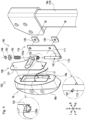
- is a rear exploded perspective view illustrating the lamp and the support mechanism.
- Fig. 5
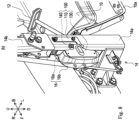
- is a rear perspective view illustrating the lamp and the support mechanism.
- Fig. 6
- is a rear perspective view illustrating a state in which a fixing portion (lamp) is lifted from a use position.
- Fig. 7
- is a rear perspective view illustrating a state in which a fixing portion (lamp) is switched to a storage position.
- Fig. 8
- is an enlarged front perspective view illustrating the lamp and the support mechanism switched to the storage position.
- Fig. 9(a)
- is a front view illustrating the lamp at a use position.
- Fig. 9(b)
- is a front view illustrating the lamp at the storage position.
- Fig. 10
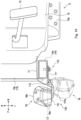
- is a partial cross-sectional plan view illustrating the lamp and the support mechanism.
- Fig. 11
- is a partial cross-sectional plan view illustrating a lamp and a support mechanism according to a second embodiment.
- In the following description, directions indicated by arrows U, D, F, B, L, and R in the drawings are defined as an upward direction, a downward direction, a forward direction, a backward direction, a left direction, and a right direction, respectively.
- First, an overall configuration of a tractor 1 according to a first embodiment of the present invention will be described mainly with reference to
Figs. 1 to 4 . - The tractor 1 mainly includes a
body frame 2, front wheels 3, a transmission device 4, rear wheels 5, a fender 6, anengine 7, abonnet 8, adriving operation unit 9, afront safety frame 14, arear safety frame 15,lamps 16,wiring 17, and asupport mechanism 100. - The
body frame 2 is disposed with its longitudinal direction oriented in a front-rear direction. A front portion of thebody frame 2 is supported by the pair of left and right front wheels 3. The transmission device 4 is provided at a rear portion of thebody frame 2. A rear portion of the transmission device 4 is supported by the pair of left and right rear wheels 5. The rear wheel 5 is covered upward and forward by a pair of the left and right fenders 6. Theengine 7 is provided in a front-rear middle portion of thebody frame 2. Theengine 7 is covered with thebonnet 8. The drivingoperation unit 9 for an operator to drive the tractor 1 is provided behind theengine 7. - The driving
operation unit 9 is provided with astep 10, a steeringpost 11, aclutch pedal 12, aseat 13, and the like. - The
step 10 forms a floor surface for an operator to board. Anauxiliary step 10a for assisting the operator to board thestep 10 is provided on a side of thestep 10. The steeringpost 11 is provided at a front portion of the drivingoperation unit 9. Asteering wheel 11a for steering the tractor 1 is provided above the steeringpost 11. - The
clutch pedal 12 for operating a clutch mechanism (not illustrated) of the tractor 1 is provided in front of the step 10 (on the left side of the steering post 11). Furthermore, although not illustrated, various other operation pedals (accelerator pedal, brake pedal, etc.) are provided in thestep 10. Theseat 13 on which an operator sits is provided at a rear portion of the drivingoperation unit 9. - The
front safety frame 14 and therear safety frame 15 for protecting an operator on board the drivingoperation unit 9 are provided in front of and behind the drivingoperation unit 9. Thefront safety frame 14 is provided in front of the drivingoperation unit 9. Thefront safety frame 14 includes alower frame 14a fixed to a rear portion of thebody frame 2, and anupper frame 14b provided so as to be able to rock forward and backward with respect to thelower frame 14a. Therear safety frame 15 is provided behind the drivingoperation unit 9. - Each of the
lamps 16 is a lighting fixture capable of emitting light as necessary. Thelamp 16 according to the present embodiment is a lighting fixture (so-called combination lamp) that can be used for a plurality of applications (direction indicators and vehicle width lights). Thelamp 16 mainly includes alamp housing 16a and atranslucent cover 16b (seeFigs. 3 and4 ). - The
lamp housing 16a is a member provided with a light emitter (such as a light bulb) that emits light. Thetranslucent cover 16b is a member that covers the light emitter provided in thelamp housing 16a. Light from the light emitter passes through thetranslucent cover 16b and is emitted to the outside. That is, a surface of thelamp 16 on the side where thetranslucent cover 16b is provided (for example, inFig. 3(a) , a front side surface of the lamp 16) serves as an irradiation surface that irradiates the outside with light. Thewiring 17 for supplying power and transmitting a control signal is connected to a back surface (surface opposite to the irradiation surface) of the lamp 16 (lamp housing 16a) (seeFig. 4 ). - The
lamps 16 are disposed on the left and right sides of thebonnet 8 in front of the drivingoperation unit 9. Each of thelamps 16 is provided on the front safety frame 14 (more specifically, thelower frame 14a) through thesupport mechanism 100. - In such the tractor 1, the power of the
engine 7 is shifted in speed by the transmission device 4 and then transmitted to the front wheels 3 and the rear wheels 5 through an appropriate power transmission mechanism. The front wheels 3 and the rear wheels 5 are rotationally driven by the power of theengine 7, and the tractor 1 travels. Thesteering wheel 11a can adjust (change) a turning angle of the pair of right and left front wheels 3 and 3 according to a turning operation amount to steer the tractor 1. - Next, the configuration of the
support mechanism 100 will be described mainly with reference toFigs. 4 and5 . Note that, although thesupport mechanisms 100 are provided on the left and right sides of a vehicle body of the tractor 1, the left andright support mechanisms 100 are bilaterally symmetric. Therefore, the description below focuses on theleft support mechanism 100. - The
support mechanism 100 is for supporting thelamp 16. Thesupport mechanism 100 can switch a position of a fixing portion 130 (in turn, the lamp 16) to be described later between a use position (SeeFigs. 3 and9(a) ) where at least a part of thelamp 16 is located on an outer side of the vehicle body than the fender 6 in the left-right direction and a storage position (SeeFigs. 8 and9(b) ) where thelamp 16 is located on an inner side of the vehicle body than the fender 6. Note thatFigs. 1 to 5 illustrate a state in which the fixingportion 130 is switched to the use position. Hereinafter, the configuration of thesupport mechanism 100 will be described based on the state. Thesupport mechanism 100 mainly includes asupport portion 110, avibration proofing member 120, the fixingportion 130, and aholding mechanism 140. - The
support portion 110 illustrated inFigs. 4 and5 supports thelamp 16 through the fixingportion 130 to be described later. Thesupport portion 110 mainly includes a firstflat plate portion 111 and aninsertion portion 112. - The first
flat plate portion 111 is a portion formed in a flat plate shape with a plate surface facing left and right. The firstflat plate portion 111 is formed in an L shape in a side view including a portion extending upward and downward and a portion protruding forward from a lower portion thereof. - The
insertion portion 112 is a portion formed in a columnar shape with an axial direction facing up and down. A lower end portion of theinsertion portion 112 is fixed to a front lower portion of the firstflat plate portion 111. Thus, theinsertion portion 112 is disposed so as to protrude upward from the front lower portion of the firstflat plate portion 111. - The
vibration proofing member 120 is a member for suppressing transmission of vibration from the vehicle body of the tractor 1 to thelamp 16. Thevibration proofing member 120 is formed in a rectangular plate shape. Thevibration proofing member 120 is made of a material having vibration-proof properties, such as rubber. - The fixing
portion 130 is a portion to which thelamp 16 is fixed. The fixingportion 130 mainly includes a secondflat plate portion 131 and acylindrical portion 132. - The second
flat plate portion 131 is a portion formed in a flat plate shape with a plate surface facing forward and backward. The secondflat plate portion 131 is formed in a T-shape in rear view including a portion extending upward and downward and a portion protruding laterally (rightward) from an up-down middle portion. Arecess 131a is formed in the secondflat plate portion 131. - The
recess 131a is a portion formed by recessing an up-down central portion of the secondflat plate portion 131 rearward. Therecess 131a is formed in a substantially elliptical shape that is long in the left-right direction. - The
cylindrical portion 132 is a portion formed in a cylindrical shape with an axial direction facing up and down. Thecylindrical portion 132 is fixed to a right end portion of the secondflat plate portion 131.Notches 132a are formed in thecylindrical portion 132. - The
notches 132a are formed so as to cut out a lower end portion of thecylindrical portion 132 upward. Thenotches 132a are formed at four positions on the front, rear, left, and right of the lower end portion of thecylindrical portion 132. As a result, thenotches 132a are formed at equal intervals (every 90 degrees about an axis of the cylindrical portion 132). - The
holding mechanism 140 holds the fixingportion 130 at the use position or the storage position. Theholding mechanism 140 mainly includes apin 141, aspring 142, aplain washer 143, and a retainingring 144. - The
pin 141 is a member formed in a cylindrical shape. Thepin 141 is provided so as to be laterally inserted through a lower portion of theinsertion portion 112. Thepin 141 is disposed such that left and right end portions respectively protrude to the left and right from theinsertion portion 112. - The
spring 142 is a member that biases the fixingportion 130 downward. Thespring 142 is formed of a compression coil spring. - The
plain washer 143 is a member formed in an annular flat plate shape. The retainingring 144 is a member engageable with theinsertion portion 112. - In the
support mechanism 100 configured as described above, the firstflat plate portion 111 is fixed to an outer surface (left side surface) of thelower frame 14a of thefront safety frame 14 with a fixing tool such as a bolt. Accordingly, thesupport portion 110 is fixed to thefront safety frame 14. At this time, thevibration proofing member 120 is disposed between thelower frame 14a and the firstflat plate portion 111. As a result, transmission of vibration from the vehicle body of the tractor 1 to the support portion 110 (in turn, the lamp 16) can be suppressed. In a state where thesupport portion 110 is fixed to thefront safety frame 14, theinsertion portion 112 is located on the front side of the front safety frame 14 (lower frame 14a). - Furthermore, the second
flat plate portion 131 is fixed to the back surface of the lamp 16 (lamp housing 16a) with a fixing tool such as a bolt. At this time, thewiring 17 connected to thelamp 16 is led out toward an inner side (right side) of the vehicle body through a space (more specifically, therecess 131a of the second flat plate portion 131) between thelamp 16 and the second flat plate portion 131 (seeFig. 10 ). - Furthermore, the
cylindrical portion 132, thespring 142, and theplain washer 143 are sequentially inserted into theinsertion portion 112. Moreover, the retainingring 144 is locked to an upper end portion of theinsertion portion 112 above theplain washer 143. The retainingring 144 can prevent thecylindrical portion 132, thespring 142, and theplain washer 143 from falling off theinsertion portion 112. - In this state, the
cylindrical portion 132 is biased downward by thespring 142, and thenotches 132a formed at the lower end portion of thecylindrical portion 132 is engaged with thepin 141 as illustrated inFig. 5 . Therefore, the rotation of thecylindrical portion 132 with respect to theinsertion portion 112 is restricted, and the fixing portion 130 (lamp 16) is held at the use position. At the use position, the fixingportion 130 is disposed such that the secondflat plate portion 131 protrudes from thecylindrical portion 132 toward an outer side (left side) of the vehicle body. Furthermore, thelamp 16 fixed to the fixingportion 130 is disposed with the irradiation surface (translucent cover 16b) facing forward. - In this way, the
lamp 16 is attached to thefront safety frame 14 through thesupport mechanism 100. In this manner, thelamp 16 can be firmly supported by attaching thelamp 16 to thefront safety frame 14 having relatively high rigidity of the tractor 1. - Furthermore, as illustrated in
Fig. 10 , thelamp 16 is disposed on the front side of thefront safety frame 14. That is, thelamp 16 is disposed on the front side of thestep 10 on which the operator boards. Thewiring 17 connected to thelamp 16 is disposed to pass through the inside (right side) of the front safety frame 14 (lower frame 14a). Thewiring 17 is appropriately connected to a battery serving as a power supply, a control board (not illustrated) disposed in thesteering post 11, and the like. - In a case where the fixing portion 130 (lamp 16) is switched from the use position to the storage position, as illustrated in
Fig. 6 , the fixingportion 130 is lifted up against the biasing force of thespring 142. As a result, the engagement between thenotches 132a and thepin 141 is released, and thecylindrical portion 132 can rotate with respect to theinsertion portion 112. - In this state, the fixing portion 130 (lamp 16) is rotated forward. When the fixing
portion 130 is rotated by 90 degrees from the use position, a position of thenotches 132a different from thenotches 132a with which thepin 141 is engaged at the use position coincides with a position of thepin 141. In this state, as illustrated inFig. 7 , the fixingportion 130 is lowered to engage thenotches 132a with thepin 141. Consequently, the fixing portion 130 (lamp 16) can be held at the storage position. - Note that by performing an operation opposite to the above-described operation, the fixing portion 130 (lamp 16) can be switched from the storage position to the use position.
- Hereinafter, an arrangement of the
lamp 16 configured as described above at the use position and the storage position will be described. - In a case where the
lamp 16 is used, such as a case where the tractor 1 travels on a road, thelamp 16 is switched to the use position. As illustrated inFig. 9(a) , in a state where thelamp 16 is switched to the use position from the viewpoint of viewing the tractor 1 from the front direction (front view), a left end of thelamp 16 is located on an outer side (left side) of an outer end of the fender 6 (see an auxiliary line L1 in the drawing). In this way, at the use position, thelamp 16 can be positioned relatively outside, so that light of thelamp 16 is hardly blocked by thebonnet 8, and the front of the tractor 1 is easily illuminated by the light from thelamp 16. Furthermore, thelamp 16 can be easily visually recognized from the front of the tractor 1. - On the other hand, in a case where the
lamp 16 does not need to be used, such as a case where work is performed in a field, thelamp 16 can be switched to the storage position. As illustrated inFig. 9(b) , in a state where thelamp 16 is switched to the storage position from the viewpoint of viewing the tractor 1 from the front direction (front view), thelamp 16 is located on an inner side (right side) of the outer end of the fender 6 (see the auxiliary line L1 in the drawing). In this manner, at the storage position, thelamp 16 can be positioned inside the fender 6, so that thelamp 16 can be prevented from interfering with surrounding crops, obstacles, and the like. This enables the tractor 1 to perform work in a narrow place. Furthermore, damage to the crops and damage to thelamp 16 can be suppressed. - Furthermore, as indicated by a solid line in
Fig. 10 , in a state where thelamp 16 is switched to the storage position, the irradiation surface (translucent cover 16b) of thelamp 16 is disposed to face the inside (right side) of the vehicle body. This can effectively prevent the irradiation surface of thelamp 16 from being damaged. Moreover, in this state, since the secondflat plate portion 131 is located on the outer side (left side) of thelamp 16, thelamp 16 can be protected from the outer side by the secondflat plate portion 131, and furthermore, damage to thelamp 16 can be effectively suppressed. - Furthermore, as illustrated in
Fig. 10 , in the state where thelamp 16 is switched to the storage position, at least a part of thelamp 16 is disposed so as to be located inside the vehicle body with respect to an outer surface (see an auxiliary line L2 in the drawing) of the front safety frame 14 (lower frame 14a). This can effectively prevent thelamp 16 from being damaged. - Furthermore, as illustrated in
Fig. 10 , in a case where thelamp 16 is switched from the use position to the storage position, the lamp rotates forward. As a result, since thelamp 16 can be moved in a direction away from thestep 10 on which the operator boards, it is possible to prevent thelamp 16 from hindering the work (for example, getting in and out ofstep 10, operation of theclutch pedal 12, and the like) by the operator. - As described above, the tractor 1 (working vehicle) according to the present embodiment includes: the fixing
portion 130 to which thelamp 16 is fixed; and thesupport portion 110 that supports the fixingportion 130 and is capable of switching a position of the fixingportion 130 between the use position where at least a part of thelamp 16 is located on the outer side of the vehicle body with respect to the fender 6 and the storage position where thelamp 16 is located on the inner side of the vehicle body with respect to the fender 6. - With such a configuration, by switching the position of the lamp 16 (fixing portion 130) to the storage position, it is possible to prevent the
lamp 16 from interfering with surrounding crops, obstacles, and the like. - Furthermore, the
support portion 110 supports the fixingportion 130 such that an irradiation surface of thelamp 16 faces an inside of the vehicle body in a state where the fixingportion 130 is switched to the storage position. - With such a configuration, since the irradiation surface of the
lamp 16 faces the inside of the vehicle body at the storage position, it is possible to effectively suppress damage to the lamp 16 (in particular, the irradiation surface). - Furthermore, the fixing
portion 130 includes the second flat plate portion 131 (flat plate portion) formed in a flat plate shape and fixed to a surface of thelamp 16 on a side opposite to the irradiation surface. - With this configuration, the
lamp 16 can be protected from the outside by the second flat plate portion 131 (fixing portion 130) at the storage position, and damage to thelamp 16 can be effectively suppressed. - Furthermore, the
lamp 16 is disposed on a front side of the vehicle body with respect to astep 10 for an operator to board, and thesupport portion 110 switches to the storage position by rotating the fixingportion 130 at the use position forward. - With this configuration, in a case where the
lamp 16 is switched to the storage position, thelamp 16 can be prevented from hindering the operator by being rotated in a direction away from the step 10 (forward). - Furthermore, the
support portion 110 is provided in the front safety frame 14 (safety frame) disposed on a front side of the vehicle body with respect to thestep 10. - With such a configuration, the
lamp 16 can be firmly supported. - Furthermore, the
support portion 110 supports the fixingportion 130 such that at least a part of thelamp 16 is located on an inner side of the vehicle body with respect to thefront safety frame 14 in a state where the fixingportion 130 is switched to the storage position. - With such a configuration, at least a part of the
lamp 16 is located inside the vehicle body with respect to thefront safety frame 14 at the storage position, so that it is possible to effectively suppress damage to thelamp 16. - Furthermore, the
wiring 17 connected to thelamp 16 and disposed so as to pass through an inside of the vehicle body of thefront safety frame 14 is further provided. - With this configuration, it is possible to prevent the
wiring 17 from interfering with surrounding crops, obstacles, and the like. - Furthermore, the tractor 1 includes a
holding mechanism 140 capable of holding the fixingportion 130 at the use position or the storage position. - With such a configuration, the lamp 16 (fixing portion 130) can be stably held at a predetermined position (the use position and the storage position).
- Note that the tractor 1 according to the present embodiment is an embodiment of a working vehicle according to the present invention.
- Furthermore, the second
flat plate portion 131 according to the present embodiment is an embodiment of a flat plate portion according to the present invention. - Furthermore, the
front safety frame 14 according to the present embodiment is an embodiment of a safety frame according to the present invention. - Next, a modification (second embodiment) of the present invention will be described with reference to
Fig. 11 . Asupport portion 110 according to the second embodiment is configured to switch to the storage position by rotating a fixing portion 130 (lamp 16) at the use position reward. - Specifically, at the use position, as in the first embodiment, an irradiation surface of the
lamp 16 is disposed so as to face forward (see a two-dot chain line inFig. 11 ). The fixing portion 130 (lamp 16) is rotated rearward by 90 degrees from this state, whereby the fixingportion 130 can be switched to the storage position. At the storage position, the irradiation surface of thelamp 16 faces outward. - Note that, in the second embodiment, an insertion portion 112 (rotation fulcrum of the fixing portion 130) is disposed behind a
front safety frame 14 so that the fixingportion 130 and the like do not interfere with thefront safety frame 14 when the fixingportion 130 and thelamp 16 are rotated rearward. However, the arrangement of each member is not limited thereto, and can be arbitrarily changed. - As described above, the
support portion 110 according to the second embodiment supports the fixingportion 130 such that the irradiation surface of thelamp 16 faces an outside of a vehicle body in a state where the fixingportion 130 is switched to the storage position. - With such a configuration, since the irradiation surface of the
lamp 16 faces the outside of the vehicle body at the storage position, it is possible to effectively suppress damage to a back surface (lamp housing 16a, light emitter provided in thelamp housing 16a, and the like) of thelamp 16. - Furthermore, the
support portion 110 switches to the storage position by rotating the fixingportion 130 at the use position rearward. - With such a configuration, it is possible to suppress interference with surrounding crops, obstacles, and the like by housing the fixing portion 130 (lamp 16) behind.
- Although the embodiments of the present invention have been described above, the present invention is not limited to the above configurations, and various modifications can be made within the scope of the invention described in the claims.
- For example, in the above embodiments, the tractor 1 is exemplified as the working vehicle, but the present invention can be applied to other various working vehicles (agricultural vehicles, construction vehicles, industrial vehicles, etc.).
- Furthermore, in the above embodiments, the
lamp 16 is provided in thefront safety frame 14, but may be provided in another safety frame (the rear safety frame 15) or another member (for example, the fender 6 and the like). - Furthermore, in the above embodiments, the
lamp 16 is disposed on the front side of thestep 10, but thelamp 16 may be disposed at the same position as thestep 10 in the front-rear direction, or may be disposed on the rear side of thestep 10. For example, in a case where thelamp 16 is provided behind the step 10 (in the fender 6, therear safety frame 15, or the like), thelamp 16 is configured to rotate rearward (in a direction away from the step 10), so that it is possible to suppress thelamp 16 from interfering with the operator. - Furthermore, the arrangement (position, orientation, and the like) of the lamp 16 (fixing portion 130) at the use position and the storage position is an example, and can be arbitrarily changed. For example, the configuration in which the fixing
portion 130 at the use position is rotated by 90 degrees to switch to the storage position is exemplified, but the angle at the time of switching the position can be arbitrarily changed. For example, the fixingportion 130 may be rotated 180 degrees from the use position to switch to the storage position. Furthermore, thelamp 16 may direct the irradiation surface rearward at the use position. - Furthermore, in the present embodiments, the
lamp 16 has been described as being used as a direction indicator or a vehicle width lamp, but the application of thelamp 16 is not limited thereto, and the present invention can be applied to thelamp 16 for various applications. - The present invention can be applied to a working vehicle including a lamp.
-
- 1
- Tractor
- 6
- Fender
- 9
- Step
- 14
- Front safety frame
- 16
- Lamp
- 17
- Wiring
- 100
- Support mechanism
- 110
- Support portion
- 120
- Vibration proofing member
- 130
- Fixing portion
- 131
- Second flat plate portion
- 140
- Holding mechanism
Claims (10)
- A working vehicle comprising:- a fixing portion to which a lamp is fixed; and- a support portion that supports the fixing portion and is capable of switching a position of the fixing portion between a use position where at least a part of the lamp is located on an outer side of a vehicle body with respect to a fender and a storage position where the lamp is located on an inner side of the vehicle body with respect to the fender.
- The working vehicle according to claim 1, wherein the support portion supports the fixing portion such that an irradiation surface of the lamp faces an inside of the vehicle body in a state where the fixing portion is switched to the storage position.
- The working vehicle according to claim 2, wherein the fixing portion includes a flat plate portion formed in a flat plate shape and fixed to a surface of the lamp on a side opposite to the irradiation surface.
- The working vehicle according to any one of claims 1 to 3, wherein- the lamp is disposed on a front side of the vehicle body with respect to a step for an operator to board, and- the supporting portion switches to the storage position by rotating the fixing portion at the use position forward.
- The working vehicle according to claim 4, wherein the support portion is provided in a safety frame disposed on a front side of the vehicle body with respect to the step.
- The working vehicle according to claim 5, wherein the support portion supports the fixing portion such that at least a part of the lamp is located on an inner side of the vehicle body with respect to the safety frame in a state where the fixing portion is switched to the storage position.
- The working vehicle according to claim 5 or 6, further comprising a wiring connected to the lamp and disposed so as to pass through an inside of the vehicle body of the safety frame.
- The working vehicle according to claim 1, wherein the support portion supports the fixing portion such that an irradiation surface of the lamp faces an outside of the vehicle body in a state where the fixing portion is switched to the storage position.
- The working vehicle according to claim 1, wherein the support portion switches to the storage position by rotating the fixing portion at the use position rearward.
- The working vehicle according to any one of claims 1 to 9, further comprising a holding mechanism capable of holding the fixing portion at the use position or the storage position.
Applications Claiming Priority (2)
| Application Number | Priority Date | Filing Date | Title |
|---|---|---|---|
| JP2021107069A JP7591984B2 (en) | 2021-06-28 | 2021-06-28 | Work vehicles |
| PCT/JP2022/015128 WO2023276373A1 (en) | 2021-06-28 | 2022-03-28 | Work vehicle |
Publications (2)
| Publication Number | Publication Date |
|---|---|
| EP4365374A1 true EP4365374A1 (en) | 2024-05-08 |
| EP4365374A4 EP4365374A4 (en) | 2025-04-09 |
Family
ID=84692644
Family Applications (1)
| Application Number | Title | Priority Date | Filing Date |
|---|---|---|---|
| EP22832534.6A Pending EP4365374A4 (en) | 2021-06-28 | 2022-03-28 | CONSTRUCTION EQUIPMENT |
Country Status (4)
| Country | Link |
|---|---|
| US (1) | US12128817B2 (en) |
| EP (1) | EP4365374A4 (en) |
| JP (1) | JP7591984B2 (en) |
| WO (1) | WO2023276373A1 (en) |
Families Citing this family (1)
| Publication number | Priority date | Publication date | Assignee | Title |
|---|---|---|---|---|
| JP7539360B2 (en) * | 2021-11-02 | 2024-08-23 | 株式会社クボタ | Work vehicle |
Family Cites Families (18)
| Publication number | Priority date | Publication date | Assignee | Title |
|---|---|---|---|---|
| US4234908A (en) * | 1978-07-10 | 1980-11-18 | Caterpillar Tractor Co. | Storable light assembly for vehicles |
| JPS6150845A (en) * | 1984-08-16 | 1986-03-13 | Yanmar Diesel Engine Co Ltd | Setting structure of clearance lamps for farm tractor |
| JPS6226746U (en) * | 1985-08-02 | 1987-02-18 | ||
| JPS63207750A (en) * | 1987-02-24 | 1988-08-29 | Yanmar Diesel Engine Co Ltd | Rear-view mirror attaching structure for tractor |
| JPH0325038A (en) * | 1989-06-22 | 1991-02-01 | Toyota Autom Loom Works Ltd | Head lamp for industrial vehicle |
| US6009650A (en) * | 1995-09-08 | 2000-01-04 | Lamparter; Ronald C. | Illuminated sign assembly |
| US6337623B1 (en) * | 1998-02-04 | 2002-01-08 | J. Adam Krugh, IV | Elevated warning system for vehicles |
| JP3366570B2 (en) | 1998-04-28 | 2003-01-14 | 株式会社クボタ | Work vehicle rear fender support structure |
| US6918689B2 (en) * | 2003-07-17 | 2005-07-19 | Deere & Company | Pivoting auxiliary vehicle light assembly |
| JP4456498B2 (en) * | 2005-02-09 | 2010-04-28 | ヤンマー株式会社 | Direction indicator mounting structure of work vehicle |
| US7474201B2 (en) * | 2006-04-28 | 2009-01-06 | Specialty Manufacturing, Inc. | Safety unit for use on vehicles |
| JP4606424B2 (en) * | 2007-02-07 | 2011-01-05 | ヤンマー株式会社 | Crawler work vehicle |
| JP6398896B2 (en) | 2015-07-14 | 2018-10-03 | 井関農機株式会社 | Tractor |
| US9764680B2 (en) * | 2015-07-22 | 2017-09-19 | Deere & Company | Foldable light fixture |
| JP6770491B2 (en) | 2017-08-02 | 2020-10-14 | 株式会社クボタ | License plate support mechanism and work vehicle equipped with it |
| US10829035B2 (en) * | 2019-01-28 | 2020-11-10 | Toyota Motor Engineering & Manufacturing North America, Inc. | Vehicles and bumper assemblies having a stowable lighting assembly |
| CA3052598A1 (en) * | 2019-08-21 | 2021-02-21 | Safer Zone Ltd. | Emergency vehicle safety bar with deployable swing arm |
| US11135966B1 (en) * | 2020-09-30 | 2021-10-05 | Deere & Company | Foldable light assembly |
-
2021
- 2021-06-28 JP JP2021107069A patent/JP7591984B2/en active Active
-
2022
- 2022-03-28 WO PCT/JP2022/015128 patent/WO2023276373A1/en not_active Ceased
- 2022-03-28 EP EP22832534.6A patent/EP4365374A4/en active Pending
-
2023
- 2023-12-19 US US18/544,534 patent/US12128817B2/en active Active
Also Published As
| Publication number | Publication date |
|---|---|
| JP2023005278A (en) | 2023-01-18 |
| JP7591984B2 (en) | 2024-11-29 |
| EP4365374A4 (en) | 2025-04-09 |
| WO2023276373A1 (en) | 2023-01-05 |
| US20240116435A1 (en) | 2024-04-11 |
| US12128817B2 (en) | 2024-10-29 |
Similar Documents
| Publication | Publication Date | Title |
|---|---|---|
| EP3421294B1 (en) | Go-kart | |
| JP6770491B2 (en) | License plate support mechanism and work vehicle equipped with it | |
| US12128817B2 (en) | Working vehicle | |
| CA3037782A1 (en) | Industrial vehicle and lighting device | |
| JP4185827B2 (en) | Work vehicle lights | |
| US10744927B2 (en) | Headlight assembly for a mower | |
| EP3150431A1 (en) | Two-wheeled motor vehicle | |
| US20220290399A1 (en) | Front loader and work car | |
| JP3175790U (en) | Rear wheel lighting device | |
| US7721866B2 (en) | Traveling operation device and working vehicle | |
| JP2022094436A (en) | Operation device for handlebars | |
| JP2006218973A (en) | Turn signal mounting structure for work vehicle | |
| US20250312897A1 (en) | Impact tool and impact wrench | |
| US20230364991A1 (en) | Work vehicle | |
| KR20170001126U (en) | Vehicle taillights | |
| JP2021020545A (en) | Work vehicle | |
| KR20250135718A (en) | Working machine | |
| JP2024143545A (en) | Walk-behind cultivator | |
| JP2004161270A (en) | Work vehicle lights | |
| JP6623874B2 (en) | Tractor | |
| JP2004115017A (en) | Work vehicle lights | |
| JP2014040220A (en) | Illuminator of work vehicle | |
| KR20220160237A (en) | Direction indicator lamps for agricultural machinery | |
| JPH0796852A (en) | Passenger work vehicle | |
| SE540772C2 (en) | Marking light arrangement for a vehicle |
Legal Events
| Date | Code | Title | Description |
|---|---|---|---|
| STAA | Information on the status of an ep patent application or granted ep patent |
Free format text: STATUS: THE INTERNATIONAL PUBLICATION HAS BEEN MADE |
|
| PUAI | Public reference made under article 153(3) epc to a published international application that has entered the european phase |
Free format text: ORIGINAL CODE: 0009012 |
|
| STAA | Information on the status of an ep patent application or granted ep patent |
Free format text: STATUS: REQUEST FOR EXAMINATION WAS MADE |
|
| 17P | Request for examination filed |
Effective date: 20231201 |
|
| AK | Designated contracting states |
Kind code of ref document: A1 Designated state(s): AL AT BE BG CH CY CZ DE DK EE ES FI FR GB GR HR HU IE IS IT LI LT LU LV MC MK MT NL NO PL PT RO RS SE SI SK SM TR |
|
| DAV | Request for validation of the european patent (deleted) | ||
| DAX | Request for extension of the european patent (deleted) | ||
| REG | Reference to a national code |
Ref country code: DE Ref legal event code: R079 Free format text: PREVIOUS MAIN CLASS: E02F0009000000 Ipc: B60Q0001260000 |
|
| A4 | Supplementary search report drawn up and despatched |
Effective date: 20250307 |
|
| RIC1 | Information provided on ipc code assigned before grant |
Ipc: B62D 49/06 20060101ALN20250303BHEP Ipc: B60Q 1/38 20060101ALN20250303BHEP Ipc: B60Q 1/04 20060101ALI20250303BHEP Ipc: E02F 9/00 20060101ALI20250303BHEP Ipc: B60Q 1/05 20060101ALI20250303BHEP Ipc: B60Q 1/00 20060101ALI20250303BHEP Ipc: B60Q 1/32 20060101ALI20250303BHEP Ipc: B60Q 1/26 20060101AFI20250303BHEP |