EP4365074B9 - Wasserfahrzeugantriebssystem, wasserfahrzeug und wasserfahrzeugantriebssteuerungsverfahren - Google Patents
Wasserfahrzeugantriebssystem, wasserfahrzeug und wasserfahrzeugantriebssteuerungsverfahren Download PDFInfo
- Publication number
- EP4365074B9 EP4365074B9 EP23202890.2A EP23202890A EP4365074B9 EP 4365074 B9 EP4365074 B9 EP 4365074B9 EP 23202890 A EP23202890 A EP 23202890A EP 4365074 B9 EP4365074 B9 EP 4365074B9
- Authority
- EP
- European Patent Office
- Prior art keywords
- lateral movement
- propulsion device
- hull
- propulsive force
- watercraft
- Prior art date
- Legal status (The legal status is an assumption and is not a legal conclusion. Google has not performed a legal analysis and makes no representation as to the accuracy of the status listed.)
- Active
Links
Images


Classifications
-
- B—PERFORMING OPERATIONS; TRANSPORTING
- B63—SHIPS OR OTHER WATERBORNE VESSELS; RELATED EQUIPMENT
- B63H—MARINE PROPULSION OR STEERING
- B63H25/00—Steering; Slowing-down otherwise than by use of propulsive elements; Dynamic anchoring, i.e. positioning vessels by means of main or auxiliary propulsive elements
- B63H25/42—Steering or dynamic anchoring by propulsive elements; Steering or dynamic anchoring by propellers used therefor only; Steering or dynamic anchoring by rudders carrying propellers
-
- B—PERFORMING OPERATIONS; TRANSPORTING
- B63—SHIPS OR OTHER WATERBORNE VESSELS; RELATED EQUIPMENT
- B63H—MARINE PROPULSION OR STEERING
- B63H20/00—Outboard propulsion units, e.g. outboard motors or Z-drives; Arrangements thereof on vessels
- B63H20/007—Trolling propulsion units
-
- B—PERFORMING OPERATIONS; TRANSPORTING
- B63—SHIPS OR OTHER WATERBORNE VESSELS; RELATED EQUIPMENT
- B63H—MARINE PROPULSION OR STEERING
- B63H20/00—Outboard propulsion units, e.g. outboard motors or Z-drives; Arrangements thereof on vessels
- B63H20/08—Means enabling movement of the position of the propulsion element, e.g. for trim, tilt or steering; Control of trim or tilt
-
- B—PERFORMING OPERATIONS; TRANSPORTING
- B63—SHIPS OR OTHER WATERBORNE VESSELS; RELATED EQUIPMENT
- B63H—MARINE PROPULSION OR STEERING
- B63H21/00—Use of propulsion power plant or units on vessels
- B63H21/12—Use of propulsion power plant or units on vessels the vessels being motor-driven
- B63H21/17—Use of propulsion power plant or units on vessels the vessels being motor-driven by electric motor
-
- B—PERFORMING OPERATIONS; TRANSPORTING
- B63—SHIPS OR OTHER WATERBORNE VESSELS; RELATED EQUIPMENT
- B63H—MARINE PROPULSION OR STEERING
- B63H21/00—Use of propulsion power plant or units on vessels
- B63H21/20—Use of propulsion power plant or units on vessels the vessels being powered by combinations of different types of propulsion units
-
- B—PERFORMING OPERATIONS; TRANSPORTING
- B63—SHIPS OR OTHER WATERBORNE VESSELS; RELATED EQUIPMENT
- B63H—MARINE PROPULSION OR STEERING
- B63H21/00—Use of propulsion power plant or units on vessels
- B63H21/21—Control means for engine or transmission, specially adapted for use on marine vessels
- B63H21/213—Levers or the like for controlling the engine or the transmission, e.g. single hand control levers
-
- B—PERFORMING OPERATIONS; TRANSPORTING
- B63—SHIPS OR OTHER WATERBORNE VESSELS; RELATED EQUIPMENT
- B63H—MARINE PROPULSION OR STEERING
- B63H25/00—Steering; Slowing-down otherwise than by use of propulsive elements; Dynamic anchoring, i.e. positioning vessels by means of main or auxiliary propulsive elements
- B63H25/02—Initiating means for steering, for slowing down, otherwise than by use of propulsive elements, or for dynamic anchoring
-
- B—PERFORMING OPERATIONS; TRANSPORTING
- B63—SHIPS OR OTHER WATERBORNE VESSELS; RELATED EQUIPMENT
- B63H—MARINE PROPULSION OR STEERING
- B63H20/00—Outboard propulsion units, e.g. outboard motors or Z-drives; Arrangements thereof on vessels
- B63H2020/003—Arrangements of two, or more outboard propulsion units
-
- B—PERFORMING OPERATIONS; TRANSPORTING
- B63—SHIPS OR OTHER WATERBORNE VESSELS; RELATED EQUIPMENT
- B63H—MARINE PROPULSION OR STEERING
- B63H21/00—Use of propulsion power plant or units on vessels
- B63H21/20—Use of propulsion power plant or units on vessels the vessels being powered by combinations of different types of propulsion units
- B63H2021/202—Use of propulsion power plant or units on vessels the vessels being powered by combinations of different types of propulsion units of hybrid electric type
- B63H2021/205—Use of propulsion power plant or units on vessels the vessels being powered by combinations of different types of propulsion units of hybrid electric type the second power unit being of the internal combustion engine type, or the like, e.g. a Diesel engine
-
- B—PERFORMING OPERATIONS; TRANSPORTING
- B63—SHIPS OR OTHER WATERBORNE VESSELS; RELATED EQUIPMENT
- B63H—MARINE PROPULSION OR STEERING
- B63H25/00—Steering; Slowing-down otherwise than by use of propulsive elements; Dynamic anchoring, i.e. positioning vessels by means of main or auxiliary propulsive elements
- B63H25/02—Initiating means for steering, for slowing down, otherwise than by use of propulsive elements, or for dynamic anchoring
- B63H2025/026—Initiating means for steering, for slowing down, otherwise than by use of propulsive elements, or for dynamic anchoring using multi-axis control levers, or the like, e.g. joysticks, wherein at least one degree of freedom is employed for steering, slowing down, or dynamic anchoring
-
- B—PERFORMING OPERATIONS; TRANSPORTING
- B63—SHIPS OR OTHER WATERBORNE VESSELS; RELATED EQUIPMENT
- B63H—MARINE PROPULSION OR STEERING
- B63H21/00—Use of propulsion power plant or units on vessels
- B63H21/21—Control means for engine or transmission, specially adapted for use on marine vessels
Definitions
- the present invention relates to a watercraft propulsion system, a watercraft including the watercraft propulsion system and watercraft propulsion control method for controlling a watercraft.
- US 2019/0112021 A1 discloses a watercraft which includes a port-side forward-reverse propeller and a starboard-side forward-reverse propeller, two engines that respectively drive the port-side forward-reverse propeller and the starboard-side forward-reverse propeller, two rudders respectively provided rearward of the port-side forward-reverse propeller and the starboard-side forward-reverse propeller, and a side thruster provided at the bow of the watercraft.
- US 2019/0112021 A1 further discloses that the watercraft is moved and the bow of the watercraft is turned by generating propulsive forces from the forward-reverse propellers and the side thruster according to the operation of a joystick lever. Further, description is provided regarding calibration for lateral movement, calibration for oblique movement, and calibration for bow turning. Particularly, detailed description is provided regarding the calibration for the bow turning.
- the position of the turning center of the watercraft varies depending on the structure of the hull, the arrangement of various watercraft devices, cargo, and the like and, therefore, varies from one watercraft to another. Even if propulsion devices have the same specifications, there are variations in propulsive force to be outputted for the same propulsive force command, and the propulsive forces generated by the propulsion devices do not always act on the hull in the same manner. Therefore, watercraft need to be preliminarily individually calibrated for hull behaviors, particularly for lateral hull movement, i.e., lateral translation movement without bow turning. The lateral movement is available when two or more propulsion devices are provided on the hull.
- the lateral movement can be achieved by causing the resultant vector of propulsive forces generated by two propulsion devices to act along an action line extending laterally of the hull through the turning center of the hull.
- the position of the turning center is unknown. Therefore, an operation element such as a joystick is actually operated so as to move the hull laterally, and the control states (operation states) of the propulsion devices observed at this time are stored in a memory.
- calibration is achieved. Since rightward lateral movement and leftward lateral movement are performed under different operation conditions, it is basically necessary to perform the lateral movement calibration separately for the rightward lateral movement and for the leftward lateral movement.
- said object is solved by a watercraft propulsion system having the features of independent claim 1. Moreover said object is also solved by a watercraft according to claim 7. Preferred embodiments are laid down in the dependent claims.
- Further preferred embodiments provide watercraft propulsion systems that are each able to achieve a proper hull behavior in lateral movement, and watercraft including the watercraft propulsion systems.
- the controller is configured or programmed to perform a first lateral movement control in response to the first lateral movement command to cause one of the first propulsion device and the second propulsion device to generate a reverse propulsive force and cause the other of the first propulsion device and the second propulsion device to generate a forward propulsive force, and to perform a second lateral movement control in response to the second lateral movement command to cause the one of the first propulsion device and the second propulsion device to generate a forward propulsive force and cause the other of the first propulsion device and the second propulsion device to generate a reverse propulsive force.
- the controller includes a memory to store a first lateral movement thrust ratio indicating a ratio between the forward propulsive force and the reverse propulsive force in the first lateral movement control and a second lateral movement thrust ratio indicating a ratio between the forward propulsive force and the reverse propulsive force in the second lateral movement control.
- the controller is configured or programmed to set the forward propulsive force and the reverse propulsive force to be generated in the first lateral movement control according to the first lateral movement thrust ratio stored in the memory, and to set the forward propulsive force and the reverse propulsive force to be generated in the second lateral movement control according to the second lateral movement thrust ratio stored in the memory.
- the first propulsion device and the second propulsion device are attachable to the hull asymmetrically with respect to the center line of the hull. Therefore, for example, a percentage of a propulsive force effectively applied from the first propulsion device to the hull and a percentage of a propulsive force effectively applied from the second propulsion device to the hull are not necessarily equal to each other, but are dependent on interactions between the hull and water jets generated by the respective propulsion devices. Specifically, when a water jet generated by one of the first propulsion device and the second propulsion device is directed toward the hull for the lateral movement, the propulsive force effectively acting on the hull is influenced by the degree of the interaction between the water jet and the hull.
- the influence on the lateral movement in one of opposite lateral directions and the influence on the lateral movement in the other lateral direction appear asymmetrically with respect to the center line of the hull.
- the initial value of the other of the first lateral movement thrust ratio and the second lateral movement thrust ratio is set to the inverse of the one of the first lateral movement thrust ratio and the second lateral movement thrust ratio.
- the first propulsion device is an engine propulsion device
- the second propulsion device is an electric propulsion device
- the first propulsion device is located on the center line, and the second propulsion device is offset from the center line.
- the first propulsion device and the second propulsion device are in different positional relationships with respect to the center line of the hull, so that the interaction between the hull and the water jet generated by the first propulsion device and the interaction between the hull and the water jet generated by the second propulsion device appear asymmetrically with respect to the center of the hull.
- the first propulsion device and the second propulsion device are attachable to the stern of the hull.
- the first propulsion device includes a propeller rotation axis lower than the keel of the hull
- the second propulsion device includes a propeller rotation axis higher than the keel of the hull.
- the propeller rotation axis of the first propulsion device is located lower than the keel of the hull and, therefore, the interaction between the hull and the water jet generated by the first propulsion device is smaller.
- the propeller rotation axis of the second propulsion device is located higher than the keel of the hull and, therefore, the interaction between the hull and the water jet generated by the second propulsion device is greater.
- the interaction between the hull and the water jet generated by the first propulsion device and the interaction between the hull and the water jet generated by the second propulsion device are asymmetrical with respect to the center of the hull.
- a watercraft propulsion system including a first propulsion device attachable to a hull, a second propulsion device attachable to the hull asymmetrically to the first propulsion device with respect to the anteroposterior center line of the hull, a lateral movement command generator to generate a first lateral movement command to laterally move the hull in one of a rightward direction and a leftward direction, and to generate a second lateral movement command to laterally move the hull in the other of the rightward direction and the leftward direction, and a controller.
- the controller is configured or programmed to perform a first lateral movement control in response to the first lateral movement command to cause one of the first propulsion device and the second propulsion device to generate a reverse propulsive force and cause the other of the first propulsion device and the second propulsion device to generate a forward propulsive force, and to perform a second lateral movement control in response to the second lateral movement command to cause the one of the first propulsion device and the second propulsion device to generate a forward propulsive force and cause the other of the first propulsion device and the second propulsion device to generate a reverse propulsive force.
- a magnitude relationship between the forward propulsive force and the reverse propulsive force in the first lateral movement control and a magnitude relationship between the forward propulsive force and the reverse propulsive force in the second lateral movement control are reversed from each other.
- the first propulsion device and the second propulsion device are attached to the hull asymmetrically with respect to the center line of the hull. Therefore, for example, the percentage of a propulsive force effectively applied from the first propulsion device to the hull and the percentage of a propulsive force effectively applied from the second propulsion device to the hull are not necessarily equal to each other, but are dependent on interactions between the hull and water jets generated by the respective propulsion devices. Specifically, when a water jet generated by one of the first propulsion device and the second propulsion device is directed toward the hull for the lateral movement, the propulsive force effectively acting on the hull is influenced by the degree of the interaction between the water jet and the hull.
- the influence on the lateral movement in one of opposite lateral directions and the influence on the lateral movement in the other lateral direction are asymmetrical with respect to the center line of the hull.
- the magnitude relationship between the forward propulsive force and the reverse propulsive force in the first lateral movement control and the magnitude relationship between the forward propulsive force and the reverse propulsive force in the second lateral movement control are reversed from each other. This makes it possible to achieve a proper hull behavior for the lateral movement in either direction.
- Another further preferred embodiment provides a watercraft including a hull, and a watercraft propulsion system attached to the hull and including any of the above-described features.
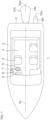
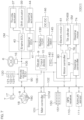
- FIG. 1 is a plan view showing an exemplary construction of a watercraft 1 mounted with a watercraft propulsion system 100 according to a preferred embodiment.
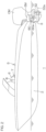
- FIG. 2 is a side view of the watercraft 1 as seen from a left side with respect to the bow direction of the watercraft 1.
- the watercraft 1 includes a hull 2, an engine outboard motor OM attached to the hull 2, and an electric outboard motor EM attached to the hull 2.
- the engine outboard motor OM and the electric outboard motor EM are examples of the propulsion devices.
- the engine outboard motor OM is an exemplary main propulsion device.
- the electric outboard motor EM is an exemplary auxiliary propulsion device having a lower rated output than the main propulsion device.
- the engine outboard motor OM is an example of the engine propulsion device including an engine as its power source, and corresponds to the first propulsion device.
- the electric outboard motor EM is an example of the electric propulsion device including an electric motor as its power source, and corresponds to the second propulsion device.
- the engine outboard motor OM and the electric outboard motor EM are attached to the stern 3 of the watercraft 1. More specifically, the engine outboard motor OM and the electric outboard motor EM are disposed side by side transversely of the hull 2 on the stern 3. In this example, the engine outboard motor OM is disposed on a transversely middle portion of the stern 3, and the electric outboard motor EM is disposed outward (leftward in this example) of the transversely middle portion of the stern 3. That is, the engine outboard motor OM is disposed on the anteroposterior center line 2a of the hull 2. The electric outboard motor EM is laterally offset from the center line 2a. Therefore, the electric outboard motor EM is attached to the hull 2 asymmetrically to the engine outboard motor OM with respect to the center line 2a.
- the engine outboard motor OM includes a propeller 32 rotatable about a first propeller rotation axis 32a.
- the electric outboard motor EM includes a propeller 60 rotatable about a second propeller rotation axis 60a.
- the first propeller rotation axis 32a and the second propeller rotation axis 60a are not coaxial, but have different axes.
- the first propeller rotation axis 32a and the second propeller rotation axis 60a are spaced apart from each other transversely of the hull 2 as seen in plan. Further, the first propeller rotation axis 32a and the second propeller rotation axis 60a are located at different heights.
- the first propeller rotation axis 32a extends in a direction conforming to the steering angle and the trim angle of the engine outboard motor OM.
- the second propeller rotation axis 60a extends in a direction conforming to the steering angle and the trim angle of the electric outboard motor EM. Therefore, the first propeller rotation axis 32a and the second propeller rotation axis 60a may be parallel or nonparallel, and are not in a fixed relationship. Where the propeller 32 of the engine outboard motor OM and the propeller 60 of the electric outboard motor EM are both located underwater, the first propeller rotation axis 32a is located lower than the second propeller rotation axis 60a.
- a usable space 4 for passengers is provided inside the hull 2.
- a helm seat 5 is provided in the usable space 4.
- a steering wheel 6, a remote control lever 7, a joystick 8, a gauge 9 (display panel) and the like are provided in association with the helm seat 5.
- the steering wheel 6 is an operation element operable by an operator to change the course of the watercraft 1.
- the remote control lever 7 is an operation element operable by the operator to change the magnitude (output) and the direction (forward or reverse direction) of the propulsive force of the engine outboard motor OM, and corresponds to an acceleration operation element.
- the joystick 8 is an operation element operable instead of the steering wheel 6 and the remote control lever 7 by the operator for maneuvering the watercraft.
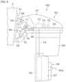
- FIG. 3 is a side view showing the structure of the engine outboard motor OM by way of example.
- the engine outboard motor OM includes a propulsion unit 20, and an attachment mechanism 21 that attaches the propulsion unit 20 to the hull 2.
- the attachment mechanism 21 includes a clamp bracket 22 detachably fixed to a transom plate provided on the stern 3 of the hull 2, and a swivel bracket 24 connected to the clamp bracket 22 pivotally about a tilt shaft 23 (horizontal pivot shaft).
- the propulsion unit 20 is attached to the swivel bracket 24 pivotally about a steering shaft 25.
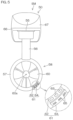
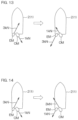
- FIG. 6B is a schematic diagram showing how the hull 2 influences the water jet around the propeller 60 of the electric outboard motor EM. Since the second propeller rotation axis 60a is located at a higher level than the keel 2b, the water jet around the propeller 60 interferes with the hull 2. In FIG. 6B , the propeller 60 is rotated in reverse, and takes in water from the rear side of the hull 2 and discharges the water toward the hull 2. The discharged water jet interferes with the hull 2 to stagnate such that the propulsive force is reduced.
- the remote control ECU 90 outputs a propulsive force command to the engine ECU 40 via the outboard motor control network 105.
- the propulsive force command includes a shift command that indicates the shift position of the shift mechanism 33, and an output command that indicates the output (specifically, the rotation speed) of the engine 30. Further, the remote control ECU 90 outputs the steering angle command to the steering ECU 41 via the outboard motor control network 105.
- a steering control operation is performed according to the operation angle signal generated by the steering wheel unit 16, and a propulsive force control operation is performed according to the operation signal (operation position signal) of the remote control lever 7.
- the ordinary mode is a default control mode of the main controller 101.
- the steering control operation specifically, the steering ECU 41 drives the steering actuator 44 according to the operation angle signal generated by the steering wheel unit 16 or the steering angle command applied from the remote control ECU 90.
- the body of the engine outboard motor OM is steered leftward and rightward such that the propulsive force direction is changed leftward and rightward with respect to the hull 2.
- the main controller 101 defines the anteroposterior inclination of the joystick 8 as the propulsive force command (the shift command and the output command), and ignores the lateral inclination of the joystick 8. That is, when the joystick 8 is inclined, only the anteroposterior directional component of the inclination direction of the joystick 8 serves as an effective input, and is defined as the propulsive force command. More specifically, if the anteroposterior directional component has a value indicating the forward inclination, the anteroposterior directional component is defined as a forward shift command.
- the main controller 101 controls the output and the steering angle of at least one of the engine outboard motor OM and the electric outboard motor EM based on the position data and the speed data generated by the GPS receiver 110.
- the positional change of the hull 2 is reduced.
- the main controller 101 controls the output and the steering angle of at least one of the engine outboard motor OM and the electric outboard motor EM based on the azimuth data generated by the azimuth sensor 111.
- the azimuthal change of the hull 2 is reduced.
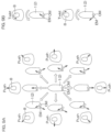
- the steering angles of the engine outboard motor OM and the electric outboard motor EM are controlled so that propulsive force action lines 201, 202 respectively defined by lines extending along the vectors OV, EV of the propulsive forces generated by the engine outboard motor OM and the electric outboard motor EM cross each other in the hull 2 as seen in plan.
- the resultant force of the propulsive forces generated by the two propulsion devices may be considered to act on the hull 2 at the intersection of the two propulsive force action lines 201, 202.
- the resultant force action line 203 defined by the line extending along the vector RV of the resultant force passes through the turning center G of the hull 2, the resultant force applies no moment to the hull 2, so that the hull 2 can translate.
- the resultant force action line 203 passing through the turning center G is parallel to the transverse direction of the hull 2, the hull 2 can be moved laterally leftward.
- the steering angles, the forward/reverse drive directions, and the outputs of the engine outboard motor OM and the electric outboard motor EM are thus controlled in the leftward lateral movement control.
- the position of the turning center G varies depending on the construction of the watercraft. Therefore, calibration should be preliminarily performed for the rightward lateral movement control and for the leftward lateral movement control. This makes it possible to achieve the lateral movement as intended by the operator according to the operation of the joystick 8.
- a procedure and a process in which the rightward lateral movement calibration is first performed and then the leftward lateral movement calibration is performed will hereinafter be described.
- a procedure and a process in which the leftward lateral movement calibration is first performed and then the rightward lateral movement calibration is performed can be provided by exchanging between "the rightward lateral movement" and "the leftward lateral movement" in the following description.
- FIG. 12 is a flowchart showing the process to be performed by the main controller 101 for the lateral movement calibration.
- the operator can start the rightward lateral movement calibration by performing a predetermined calibration start operation to apply a calibration mode command to the main controller 101.
- the calibration start operation may be, for example, long-pressing of the joystick button 181. If the calibration start operation is performed (YES in Step S1), the control mode of the main controller 101 is switched to the calibration mode (Step S2). The operator may be notified of the calibration mode by an indicator such as an LED lamp (not shown) provided in the joystick unit 18.
- the operator performs a rightward lateral movement operation, i.e., inclines the joystick 8 rightward, for the rightward lateral movement calibration.
- the operator observes the behavior of the hull 2. If the hull 2 is moved right-forward, the operator changes the inclination direction of the joystick 8 to a right rearward direction in order to correct the hull movement. If the hull 2 is moved right-rearward, the operator changes the inclination direction of the joystick 8 to a right forward direction in order to correct the hull movement. If the bow of the hull 2 is turned clockwise, the operator twists the joystick 8 counterclockwise in order to correct the bow turning. If the bow of the hull 2 is turned counterclockwise, the operator twists the joystick 8 clockwise in order to correct the bow turning.
- the operation signal of the joystick 8 is inputted from the joystick unit 18 to the main controller 101.
- the main controller 101 changes the propulsive force command and the steering angle command to be applied to the engine outboard motor OM and the electric outboard motor EM (Step S4). If the operation states of the engine outboard motor OM and the electric outboard motor EM are such that the hull 2 can thus achieve the rightward lateral movement behavior, the operator performs a decision operation (YES in Step S5).
- the joystick button 181 may be pressed for the decision operation.
- the calibration value includes the steering angle of the engine outboard motor OM, the steering angle of the electric outboard motor EM, and a thrust ratio (hereinafter referred to as "rightward lateral movement thrust ratio") each observed when the decision operation (Step S5) is performed.
- the rightward lateral movement thrust ratio is a thrust ratio observed when the rightward lateral movement is achieved (when the decision operation is performed) in the calibration mode.
- the main controller 101 computes the rightward lateral movement thrust ratio based on the forward thrust (output command value) and the reverse thrust (output command value) observed when the decision operation (Step S5) is performed, and writes the rightward lateral movement thrust ratio in the memory 101M (Step S7).
- the main controller 101 determines whether or not a calibration state value is a value indicating "incompletion” (Step S8). If the calibration is completed, the main controller 101 sets the calibration state value to a value indicating "completion.” If the calibration is not completed, the main controller 101 sets the calibration state value to the value indicating "incompletion.”
- the main controller 101 computes the leftward lateral movement thrust ratio based on the rightward lateral movement thrust ratio, and overwrites the default value with the computed value in the memory 101M (Step S9). Specifically, the main controller 101 computes the inverse of the rightward lateral movement thrust ratio as the leftward lateral movement thrust ratio, and sets the computed leftward lateral movement thrust ratio in the memory 101M. When the leftward lateral movement calibration is thereafter performed, the leftward lateral movement thrust ratio thus set is used as an initial value.
- the leftward lateral movement thrust ratio is a ratio between a forward thrust and a reverse thrust to be used for the leftward lateral movement in the joystick mode.
- Step S10 the main controller 101 changes the calibration state value to "completion” (Step S10), and switches its control mode to the joystick mode (Step S11). If the calibration state value is not "incompletion” in Step S8, i.e., if the calibration state value is "completion” (NO in Step S8), Steps S9 and S10 are skipped, and the control mode is switched to the joystick mode (Step S11).
- Step S6 If the joystick 8 is in the neutral position (YES in Step S6) when the decision operation (Step S5) is performed, the main controller 101 determines that the reset operation is performed to reset the calibration value to the default value. In this case, the main controller 101 resets the calibration value to the default value (Step S12), and sets the calibration state value to "incompletion" (Step S13). Thereafter, the control mode is switched to the joystick mode (Step S11).
- the operator can start the leftward lateral movement calibration by performing the predetermined calibration start operation. If the calibration start operation is performed (YES in Step S1), the control mode of the main controller 101 is switched to the calibration mode (Step S2).
- the main controller 101 Upon the switching to the calibration mode, the main controller 101 reads out a calibration value from the memory 101M and, when the operator operates the joystick 8, the main controller 101 generates a propulsive force command and a steering angle command by using the calibration value (Step S3). If the leftward lateral movement calibration is performed after the rightward lateral movement calibration, the leftward lateral movement thrust ratio as the calibration value has been set to the inverse of the rightward lateral movement thrust ratio (see Step S9). This value is used as the initial value of the leftward lateral movement thrust ratio for the leftward lateral movement calibration.
- the operator performs a leftward lateral movement operation, i.e., inclines the joystick 8 leftward, for the leftward lateral movement calibration.
- the operator observes the behavior of the hull 2. If the hull 2 is moved left-forward, the operator changes the inclination direction of the joystick 8 to a left rearward direction in order to correct the hull movement. If the hull 2 is moved left-rearward, the operator changes the inclination direction of the joystick 8 to a left forward direction in order to correct the hull movement. If the bow of the hull 2 is turned clockwise, the operator twists the joystick 8 counterclockwise in order to correct the bow turning. If the bow of the hull 2 is turned counterclockwise, the operator twists the joystick 8 clockwise in order to correct the bow turning.
- the main controller 101 determines whether or not the joystick 8 is in the neutral position (Step S6). If the joystick 8 is not in the neutral position, a leftward lateral movement calibration value is written and set in the memory 101M (Step S7). The leftward lateral movement calibration value is used for the computation of the propulsive force command and the steering angle command when the leftward lateral movement operation is thereafter performed on the joystick 8 in the joystick mode.
- the leftward lateral movement calibration value includes the steering angle of the engine outboard motor OM, the steering angle of the electric outboard motor EM, and a thrust ratio (leftward lateral movement thrust ratio) each observed when the decision operation is performed. At this time, the leftward lateral movement thrust ratio is written in the memory 101M.
- the leftward lateral movement calibration is quickly completed because the operator does not need to perform various operations for the correction of the hull behavior.
- Step S8 the calibration state value is "completion" (YES in Step S8), so that the main controller 101 skips Steps S9 and S10 and switches its control mode to the joystick mode (Step S11).
Landscapes
- Chemical & Material Sciences (AREA)
- Engineering & Computer Science (AREA)
- Combustion & Propulsion (AREA)
- Mechanical Engineering (AREA)
- Ocean & Marine Engineering (AREA)
- Control Of Vehicle Engines Or Engines For Specific Uses (AREA)
Claims (12)
- Ein Wasserfahrzeug-Antriebssystem (100), das umfasst:eine erste Antriebsvorrichtung (OM), die konfiguriert ist, um an einem Rumpf (2) eines Wasserfahrzeugs (1) anbringbar ist;eine zweite Antriebsvorrichtung (EM), die konfiguriert ist, um an dem Rumpf (2) anbringbar zu sein, asymmetrisch zu der ersten Antriebsvorrichtung (OM) in Bezug auf eine anteroposteriore Mittellinie (2a) des Rumpfes (2);einen Querbewegungsbefehlsgenerator (18), der konfiguriert ist, um einen ersten Querbewegungsbefehl zu erzeugen und den Rumpf (2) in einer von einer rechten Richtung und einer linken Richtung in Bezug auf den Rumpf (2) des Wasserfahrzeugs (1) zu bewegen, und konfiguriert ist, um einen zweiten Querbewegungsbefehl zu erzeugen und den Rumpf (2) in die andere von der rechten Richtung und der linken Richtung in Bezug auf den Rumpf (2) des Wasserfahrzeugs (1) zu bewegen, und gekennzeichnet durcheine Steuerung (101), die konfiguriert oder programmiert ist, um eine erste Querbewegungssteuerung durchzuführen, in Erwiderung auf den ersten Querbewegungsbefehl, der von dem Querbewegungsbefehlsgenerator (18) empfangen ist, um eine von der ersten Antriebsvorrichtung (OM) und der zweiten Antriebsvorrichtung (EM) zu steuern, um eine Rückwärtsantriebskraft in Bezug auf den Rumpf (2) des Wasserfahrzeugs (1) zu erzeugen, und um die andere der ersten Antriebsvorrichtung (OM) und der zweiten Antriebsvorrichtung (EM) zu steuern, um eine Vorwärtsantriebskraft in Bezug auf den Rumpf (2) des Wasserfahrzeugs (1) zu erzeugen, und um eine zweite Querbewegungssteuerung durchzuführen, in Erwiderung auf den zweiten Querbewegungsbefehl, der von dem Querbewegungsbefehlsgenerator (18) empfangen ist, um eine von der ersten Antriebsvorrichtung (OM) und der zweiten Antriebsvorrichtung (EM) zu steuern, um eine Vorwärtsantriebskraft in Bezug auf den Rumpf (2) des Wasserfahrzeugs (1) zu erzeugen, und um die andere der ersten Antriebsvorrichtung (OM) und der zweiten Antriebsvorrichtung (EM) zu steuern, um eine Rückwärtsantriebskraft in Bezug auf den Rumpf (2) des Wasserfahrzeugs (1) zu erzeugen; wobeidie Steuerung (101) einen Speicher (101M) enthält, der konfiguriert ist, um ein erstes Querbewegungs-Schubverhältnis, das ein Verhältnis zwischen der Vorwärtsantriebskraft und der Rückwärtsantriebskraft in der ersten Querbewegungssteuerung angibt, und ein zweites Querbewegungs-Schubverhältnis, das ein Verhältnis zwischen der Vorwärtsantriebskraft und der Rückwärtsantriebskraft in der zweiten Querbewegungssteuerung angibt, zu speichern, und die Steuerung (101) konfiguriert oder programmiert ist, um die Vorwärtsantriebskraft und die Rückwärtsantriebskraft, die in der ersten Querbewegungssteuerung zu erzeugen sind, gemäß dem ersten Querbewegungs-Schubverhältnis, das in dem Speicher (101M) gespeichert ist, einzustellen und die Vorwärtsantriebskraft und die Rückwärtsantriebskraft, die in der zweiten Querbewegungssteuerung zu erzeugen sind, gemäß dem zweiten Querbewegungs-Schubverhältnis, das in dem Speicher (101M) gespeichert ist, einzustellen;die Steuerung (101) konfiguriert oder programmiert ist, um das erste Querbewegungs-Schubverhältnis und das zweite Querbewegungs-Schubverhältnis in einem Kalibrierungsmodus einzustellen und, wenn eines des ersten Querbewegungs-Schubverhältnisses und des zweiten Querbewegungs-Schubverhältnisses in dem Kalibrierungsmodus eingestellt ist, einen Anfangswert des anderen des ersten Querbewegungs-Schubverhältnisses und des zweiten Querbewegungs-Schubverhältnisses auf einen Kehrwert des einen Querbewegungs-Schubverhältnisses einzustellen.
- Das Wasserfahrzeug-Antriebssystem (100) gemäß Anspruch 1, wobei die erste Antriebsvorrichtung eine Motor-Antriebsvorrichtung (OM) ist, die einen Motor als ihre Energiequelle enthält, und die zweite Antriebsvorrichtung eine elektrische Antriebsvorrichtung (EM) ist, die einen Elektromotor als ihre Energiequelle enthält.
- Das Wasserfahrzeug-Antriebssystem (100) gemäß Anspruch 1 oder 2, wobei die erste Antriebsvorrichtung (OM) konfiguriert ist, um auf der Mittellinie (2a) angeordnet zu werden, und die zweite Antriebsvorrichtung (EM) konfiguriert ist, um versetzt von der Mittellinie (2a) angeordnet zu werden.
- Das Wasserfahrzeug-Antriebssystem (100) gemäß irgendeinem der Ansprüche 1 bis 3, wobei die erste Antriebsvorrichtung (OM) und die zweite Antriebsvorrichtung (EM) konfiguriert sind, um an einem Heck (3) des Rumpfes (2) angebracht zu werden.
- Das Wasserfahrzeug-Antriebssystem (100) gemäß irgendeinem der Ansprüche 1 bis 4, wobei die erste Antriebsvorrichtung (OM) eine Propellerdrehachse (32a) enthält, und konfiguriert ist, um die Propellerdrehachse (32a) der ersten Antriebsvorrichtung (OM) tiefer als ein Kiel (2b) des Rumpfes (2) anzuordnen, wenn die erste Antriebsvorrichtung (OM) an dem Rumpf (2) angebracht ist; und
die zweite Antriebsvorrichtung (EM) eine Propellerdrehachse (60a) enthält, und konfiguriert ist, um die Propellerdrehachse (60a) der zweiten Antriebsvorrichtung (EM) höher als den Kiel (2b) des Rumpfes (2) anzuordnen, wenn die zweite Antriebsvorrichtung (EM) an dem Rumpf (2) angebracht ist. - Das Wasserfahrzeug-Antriebssystem (100) gemäß irgendeinem der Ansprüche 1 bis 5, wobei ein Größenverhältnis zwischen der Vorwärtsantriebskraft und der Rückwärtsantriebskraft bei der ersten Querbewegungssteuerung und ein Größenverhältnis zwischen der Vorwärtsantriebskraft und der Rückwärtsantriebskraft bei der zweiten Querbewegungssteuerung zueinander umgekehrt sind.
- Ein Wasserfahrzeug (1), das umfasst:einen Rumpf (2); unddas Wasserfahrzeug-Antriebssystem (100) gemäß irgendeinem der Ansprüche 1 bis 6, wobei die erste Antriebsvorrichtung (OM) an einem Rumpf (2) angebracht ist und die zweite Antriebsvorrichtung (EM) asymmetrisch zu der ersten Antriebsvorrichtung (OM) in Bezug auf eine anteroposteriore Mittellinie (2a) des Rumpfes (2) des Wasserfahrzeugs (1) angebracht ist.
- Das Wasserfahrzeug (1) gemäß Anspruch 7, wobei die erste Antriebsvorrichtung (OM) auf der Mittellinie (2a) angeordnet ist und die zweite Antriebsvorrichtung (EM) von der Mittellinie (2a) versetzt ist.
- Das Wasserfahrzeug (1) gemäß Anspruch 7 oder 8, wobei die erste Antriebsvorrichtung (OM) und die zweite Antriebsvorrichtung (EM) an einem Heck (3) des Rumpfes (2) angebracht sind.
- Das Wasserfahrzeug (1) gemäß irgendeinem der Ansprüche 7 bis 9, wobei die erste Antriebsvorrichtung (OM) eine Propellerdrehachse (32a) enthält, die tiefer als ein Kiel (2b) des Rumpfes (2) liegt; und
die zweite Antriebsvorrichtung (EM) eine Propellerdrehachse (60a) enthält, die höher als der Kiel (2b) des Rumpfes (2) liegt. - Ein Wasserfahrzeug-Antriebsverfahren zur Steuerung eines Wasserfahrzeugs (1), das einen Rumpf (2) und eine erste Antriebsvorrichtung (OM), die an dem Rumpf (2) angebracht ist, und einer zweiten Antriebsvorrichtung (EM), die an dem Rumpf (2) asymmetrisch zu der ersten Antriebsvorrichtung (OM) in Bezug auf eine anteroposteriore Mittellinie (2a) des Rumpfs (2) angebracht ist, hat, das Verfahren umfasst:Erzeugen eines ersten Querbewegungsbefehls, um den Rumpf (2) in eine einer rechten Richtung und einer linken Richtung quer zu bewegen,Erzeugen eines zweiten Querbewegungsbefehls, um den Rumpf (2) in die andere der rechten Richtung und der linken Richtung quer zu bewegen,Durchführen einer ersten Querbewegungssteuerung in Erwiderung auf den ersten Querbewegungsbefehl, um zu bewirken, dass eine der ersten Antriebsvorrichtung (OM) und der zweiten Antriebsvorrichtung (EM) eine Rückwärtsantriebskraft erzeugt und die andere der ersten Antriebsvorrichtung (OM) und der zweiten Antriebsvorrichtung (EM) eine Vorwärtsantriebskraft erzeugt,Durchführen einer zweiten Querbewegungssteuerung in Erwiderung auf den zweiten Querbewegungsbefehl, um zu bewirken, dass eine der ersten Antriebsvorrichtung (OM) und der zweiten Antriebsvorrichtung (EM) eine Vorwärtsantriebskraft erzeugt und die andere der ersten Antriebsvorrichtung (OM) und der zweiten Antriebsvorrichtung (EM) eine Rückwärtsantriebskraft erzeugt,Bereitstellen eines ersten Querbewegungs-Schubverhältnisses, das ein Verhältnis zwischen der Vorwärtsantriebskraft und der Rückwärtsantriebskraft bei der ersten Querbewegungssteuerung angibt, und eines zweiten Querbewegungs-Schubverhältnisses, das ein Verhältnis zwischen der Vorwärtsantriebskraft und der Rückwärtsantriebskraft bei der zweiten Querbewegungssteuerung angibt,Einstellen der Vorwärtsantriebskraft und der Rückwärtsantriebskraft, die in der ersten Querbewegungssteuerung entsprechend dem ersten Querbewegungs-Schubverhältnis erzeugt werden sollen,Einstellen der Vorwärtsantriebskraft und der Rückwärtsantriebskraft, die in der zweiten Querbewegungssteuerung entsprechend dem zweiten Querbewegungs-Schubverhältnis erzeugt werden sollen,Einstellen des ersten Querbewegungs-Schubverhältnisses und des zweiten Querbewegungs-Schubverhältnisses in einem Kalibrierungsmodus, und, wenn eines des ersten Querbewegungs-Schubverhältnisses und des zweiten Querbewegungs-Schubverhältnisses in dem Kalibrierungsmodus eingestellt ist, Einstellen eines Anfangswertes des anderen des ersten Querbewegungs-Schubverhältnisses und des zweiten Querbewegungs-Schubverhältnisses auf einen Kehrwert des einen Querbewegungs-Schubverhältnisses.
- Das Wasserfahrzeug-Antriebsverfahren gemäß Anspruch 11, wobei ein Größenverhältnis zwischen der Vorwärtsantriebskraft und der Rückwärtsantriebskraft bei der ersten Querbewegungssteuerung und ein Größenverhältnis zwischen der Vorwärtsantriebskraft und der Rückwärtsantriebskraft bei der zweiten Querbewegungssteuerung zueinander umgekehrt sind.
Applications Claiming Priority (1)
| Application Number | Priority Date | Filing Date | Title |
|---|---|---|---|
| JP2022167330A JP2024060163A (ja) | 2022-10-19 | 2022-10-19 | 船舶推進システムおよび船舶 |
Publications (3)
| Publication Number | Publication Date |
|---|---|
| EP4365074A1 EP4365074A1 (de) | 2024-05-08 |
| EP4365074B1 EP4365074B1 (de) | 2025-01-22 |
| EP4365074B9 true EP4365074B9 (de) | 2025-04-02 |
Family
ID=88372251
Family Applications (1)
| Application Number | Title | Priority Date | Filing Date |
|---|---|---|---|
| EP23202890.2A Active EP4365074B9 (de) | 2022-10-19 | 2023-10-11 | Wasserfahrzeugantriebssystem, wasserfahrzeug und wasserfahrzeugantriebssteuerungsverfahren |
Country Status (3)
| Country | Link |
|---|---|
| US (1) | US20240228005A9 (de) |
| EP (1) | EP4365074B9 (de) |
| JP (1) | JP2024060163A (de) |
Families Citing this family (2)
| Publication number | Priority date | Publication date | Assignee | Title |
|---|---|---|---|---|
| JP2023068785A (ja) * | 2021-11-04 | 2023-05-18 | ヤマハ発動機株式会社 | 船舶推進システムおよび船舶 |
| JP2023068836A (ja) * | 2021-11-04 | 2023-05-18 | ヤマハ発動機株式会社 | 船舶推進システムおよび船舶 |
Family Cites Families (7)
| Publication number | Priority date | Publication date | Assignee | Title |
|---|---|---|---|---|
| US7882791B2 (en) * | 2007-10-30 | 2011-02-08 | Robert Huntt | Steering system and method for a motor driven craft |
| JP5337722B2 (ja) * | 2010-01-07 | 2013-11-06 | ヤマハ発動機株式会社 | 船舶用推進制御装置および船舶 |
| US8862293B2 (en) * | 2011-06-28 | 2014-10-14 | Yanmar Co., Ltd. | Ship steering device and ship steering method |
| US8807059B1 (en) * | 2011-09-08 | 2014-08-19 | Brunswick Corporation | Marine vessels and systems for laterally maneuvering marine vessels |
| JP2015116847A (ja) * | 2013-12-16 | 2015-06-25 | ヤマハ発動機株式会社 | 船舶推進システムおよびそれを備えた船舶 |
| JP6430988B2 (ja) | 2016-03-31 | 2018-11-28 | ヤンマー株式会社 | 操船装置 |
| EP4309996A1 (de) * | 2022-07-22 | 2024-01-24 | JOST Group GmbH & Co KG | Elektrisches antriebs- und lenksystem für ein wasserfahrzeug |
-
2022
- 2022-10-19 JP JP2022167330A patent/JP2024060163A/ja active Pending
-
2023
- 2023-10-11 EP EP23202890.2A patent/EP4365074B9/de active Active
- 2023-10-18 US US18/381,210 patent/US20240228005A9/en active Pending
Also Published As
| Publication number | Publication date |
|---|---|
| US20240132194A1 (en) | 2024-04-25 |
| EP4365074A1 (de) | 2024-05-08 |
| EP4365074B1 (de) | 2025-01-22 |
| JP2024060163A (ja) | 2024-05-02 |
| US20240228005A9 (en) | 2024-07-11 |
Similar Documents
| Publication | Publication Date | Title |
|---|---|---|
| EP4365074B9 (de) | Wasserfahrzeugantriebssystem, wasserfahrzeug und wasserfahrzeugantriebssteuerungsverfahren | |
| US12528572B2 (en) | Watercraft propulsion system, and watercraft | |
| US20240227998A9 (en) | Watercraft propulsion system, and watercraft | |
| US20240152146A1 (en) | Watercraft propulsion system, and watercraft including the watercraft propulsion system | |
| US12459628B2 (en) | Marine propulsion system and marine vessel | |
| US20230140720A1 (en) | Marine propulsion system and marine vessel | |
| EP4368493A1 (de) | Wasserfahrzeugantriebssystem und wasserfahrzeug mit dem wasserfahrzeugantriebssystem | |
| US12466530B2 (en) | Watercraft propulsion system, and watercraft including the watercraft propulsion system | |
| US20240228000A9 (en) | Watercraft propulsion system, and watercraft | |
| JP7684833B2 (ja) | 船舶の航行システム | |
| JP2024171008A (ja) | 船舶運転制御装置 | |
| EP4501775A1 (de) | Wasserfahrzeugantriebssystem und wasserfahrzeug | |
| EP4365071A1 (de) | Wasserfahrzeugantriebssystem, wasserfahrzeug und wasserfahrzeugantriebssteuerungsverfahren | |
| EP4378815A1 (de) | Wasserfahrzeugantriebssystem und wasserfahrzeug mit dem wasserfahrzeugantriebssystem | |
| EP4524028A1 (de) | Wasserfahrzeugantriebssystem und wasserfahrzeug | |
| US20250236380A1 (en) | Boat control system and boat | |
| JP2024101415A (ja) | 操船システムおよびそれを備える船舶 |
Legal Events
| Date | Code | Title | Description |
|---|---|---|---|
| PUAI | Public reference made under article 153(3) epc to a published international application that has entered the european phase |
Free format text: ORIGINAL CODE: 0009012 |
|
| STAA | Information on the status of an ep patent application or granted ep patent |
Free format text: STATUS: THE APPLICATION HAS BEEN PUBLISHED |
|
| AK | Designated contracting states |
Kind code of ref document: A1 Designated state(s): AL AT BE BG CH CY CZ DE DK EE ES FI FR GB GR HR HU IE IS IT LI LT LU LV MC ME MK MT NL NO PL PT RO RS SE SI SK SM TR |
|
| STAA | Information on the status of an ep patent application or granted ep patent |
Free format text: STATUS: REQUEST FOR EXAMINATION WAS MADE |
|
| 17P | Request for examination filed |
Effective date: 20240618 |
|
| RBV | Designated contracting states (corrected) |
Designated state(s): AL AT BE BG CH CY CZ DE DK EE ES FI FR GB GR HR HU IE IS IT LI LT LU LV MC ME MK MT NL NO PL PT RO RS SE SI SK SM TR |
|
| P01 | Opt-out of the competence of the unified patent court (upc) registered |
Free format text: CASE NUMBER: APP_37576/2024 Effective date: 20240624 |
|
| RIC1 | Information provided on ipc code assigned before grant |
Ipc: B63H 25/02 20060101ALI20240903BHEP Ipc: B63H 25/42 20060101ALI20240903BHEP Ipc: B63H 21/20 20060101ALI20240903BHEP Ipc: B63H 21/17 20060101ALI20240903BHEP Ipc: B63H 20/00 20060101AFI20240903BHEP |
|
| GRAP | Despatch of communication of intention to grant a patent |
Free format text: ORIGINAL CODE: EPIDOSNIGR1 |
|
| STAA | Information on the status of an ep patent application or granted ep patent |
Free format text: STATUS: GRANT OF PATENT IS INTENDED |
|
| INTG | Intention to grant announced |
Effective date: 20241030 |
|
| RAP3 | Party data changed (applicant data changed or rights of an application transferred) |
Owner name: YAMAHA HATSUDOKI KABUSHIKI KAISHA |
|
| RIN1 | Information on inventor provided before grant (corrected) |
Inventor name: IKEGAYA, YUJI |
|
| GRAS | Grant fee paid |
Free format text: ORIGINAL CODE: EPIDOSNIGR3 |
|
| GRAA | (expected) grant |
Free format text: ORIGINAL CODE: 0009210 |
|
| STAA | Information on the status of an ep patent application or granted ep patent |
Free format text: STATUS: THE PATENT HAS BEEN GRANTED |
|
| AK | Designated contracting states |
Kind code of ref document: B1 Designated state(s): AL AT BE BG CH CY CZ DE DK EE ES FI FR GB GR HR HU IE IS IT LI LT LU LV MC ME MK MT NL NO PL PT RO RS SE SI SK SM TR |
|
| REG | Reference to a national code |
Ref country code: GB Ref legal event code: FG4D |
|
| REG | Reference to a national code |
Ref country code: CH Ref legal event code: EP |
|
| REG | Reference to a national code |
Ref country code: IE Ref legal event code: FG4D |
|
| REG | Reference to a national code |
Ref country code: DE Ref legal event code: R096 Ref document number: 602023001771 Country of ref document: DE |
|
| REG | Reference to a national code |
Ref country code: NL Ref legal event code: FP |
|
| REG | Reference to a national code |
Ref country code: CH Ref legal event code: PK Free format text: BERICHTIGUNG B9 |
|
| PG25 | Lapsed in a contracting state [announced via postgrant information from national office to epo] |
Ref country code: RS Free format text: LAPSE BECAUSE OF FAILURE TO SUBMIT A TRANSLATION OF THE DESCRIPTION OR TO PAY THE FEE WITHIN THE PRESCRIBED TIME-LIMIT Effective date: 20250422 |
|
| PG25 | Lapsed in a contracting state [announced via postgrant information from national office to epo] |
Ref country code: FI Free format text: LAPSE BECAUSE OF FAILURE TO SUBMIT A TRANSLATION OF THE DESCRIPTION OR TO PAY THE FEE WITHIN THE PRESCRIBED TIME-LIMIT Effective date: 20250122 |
|
| PG25 | Lapsed in a contracting state [announced via postgrant information from national office to epo] |
Ref country code: PL Free format text: LAPSE BECAUSE OF FAILURE TO SUBMIT A TRANSLATION OF THE DESCRIPTION OR TO PAY THE FEE WITHIN THE PRESCRIBED TIME-LIMIT Effective date: 20250122 |
|
| PG25 | Lapsed in a contracting state [announced via postgrant information from national office to epo] |
Ref country code: ES Free format text: LAPSE BECAUSE OF FAILURE TO SUBMIT A TRANSLATION OF THE DESCRIPTION OR TO PAY THE FEE WITHIN THE PRESCRIBED TIME-LIMIT Effective date: 20250122 |
|
| REG | Reference to a national code |
Ref country code: LT Ref legal event code: MG9D |
|
| PG25 | Lapsed in a contracting state [announced via postgrant information from national office to epo] |
Ref country code: IS Free format text: LAPSE BECAUSE OF FAILURE TO SUBMIT A TRANSLATION OF THE DESCRIPTION OR TO PAY THE FEE WITHIN THE PRESCRIBED TIME-LIMIT Effective date: 20250522 Ref country code: NO Free format text: LAPSE BECAUSE OF FAILURE TO SUBMIT A TRANSLATION OF THE DESCRIPTION OR TO PAY THE FEE WITHIN THE PRESCRIBED TIME-LIMIT Effective date: 20250422 |
|
| REG | Reference to a national code |
Ref country code: AT Ref legal event code: MK05 Ref document number: 1761293 Country of ref document: AT Kind code of ref document: T Effective date: 20250122 |
|
| PG25 | Lapsed in a contracting state [announced via postgrant information from national office to epo] |
Ref country code: HR Free format text: LAPSE BECAUSE OF FAILURE TO SUBMIT A TRANSLATION OF THE DESCRIPTION OR TO PAY THE FEE WITHIN THE PRESCRIBED TIME-LIMIT Effective date: 20250122 |
|
| PG25 | Lapsed in a contracting state [announced via postgrant information from national office to epo] |
Ref country code: LV Free format text: LAPSE BECAUSE OF FAILURE TO SUBMIT A TRANSLATION OF THE DESCRIPTION OR TO PAY THE FEE WITHIN THE PRESCRIBED TIME-LIMIT Effective date: 20250122 Ref country code: PT Free format text: LAPSE BECAUSE OF FAILURE TO SUBMIT A TRANSLATION OF THE DESCRIPTION OR TO PAY THE FEE WITHIN THE PRESCRIBED TIME-LIMIT Effective date: 20250522 |
|
| PG25 | Lapsed in a contracting state [announced via postgrant information from national office to epo] |
Ref country code: BG Free format text: LAPSE BECAUSE OF FAILURE TO SUBMIT A TRANSLATION OF THE DESCRIPTION OR TO PAY THE FEE WITHIN THE PRESCRIBED TIME-LIMIT Effective date: 20250122 Ref country code: GR Free format text: LAPSE BECAUSE OF FAILURE TO SUBMIT A TRANSLATION OF THE DESCRIPTION OR TO PAY THE FEE WITHIN THE PRESCRIBED TIME-LIMIT Effective date: 20250423 |
|
| PG25 | Lapsed in a contracting state [announced via postgrant information from national office to epo] |
Ref country code: AT Free format text: LAPSE BECAUSE OF FAILURE TO SUBMIT A TRANSLATION OF THE DESCRIPTION OR TO PAY THE FEE WITHIN THE PRESCRIBED TIME-LIMIT Effective date: 20250122 |
|
| PG25 | Lapsed in a contracting state [announced via postgrant information from national office to epo] |
Ref country code: SE Free format text: LAPSE BECAUSE OF FAILURE TO SUBMIT A TRANSLATION OF THE DESCRIPTION OR TO PAY THE FEE WITHIN THE PRESCRIBED TIME-LIMIT Effective date: 20250122 |
|
| PG25 | Lapsed in a contracting state [announced via postgrant information from national office to epo] |
Ref country code: SM Free format text: LAPSE BECAUSE OF FAILURE TO SUBMIT A TRANSLATION OF THE DESCRIPTION OR TO PAY THE FEE WITHIN THE PRESCRIBED TIME-LIMIT Effective date: 20250122 |
|
| PG25 | Lapsed in a contracting state [announced via postgrant information from national office to epo] |
Ref country code: DK Free format text: LAPSE BECAUSE OF FAILURE TO SUBMIT A TRANSLATION OF THE DESCRIPTION OR TO PAY THE FEE WITHIN THE PRESCRIBED TIME-LIMIT Effective date: 20250122 |
|
| PG25 | Lapsed in a contracting state [announced via postgrant information from national office to epo] |
Ref country code: CZ Free format text: LAPSE BECAUSE OF FAILURE TO SUBMIT A TRANSLATION OF THE DESCRIPTION OR TO PAY THE FEE WITHIN THE PRESCRIBED TIME-LIMIT Effective date: 20250122 |
|
| REG | Reference to a national code |
Ref country code: DE Ref legal event code: R097 Ref document number: 602023001771 Country of ref document: DE |
|
| PG25 | Lapsed in a contracting state [announced via postgrant information from national office to epo] |
Ref country code: RO Free format text: LAPSE BECAUSE OF FAILURE TO SUBMIT A TRANSLATION OF THE DESCRIPTION OR TO PAY THE FEE WITHIN THE PRESCRIBED TIME-LIMIT Effective date: 20250122 |
|
| PG25 | Lapsed in a contracting state [announced via postgrant information from national office to epo] |
Ref country code: SK Free format text: LAPSE BECAUSE OF FAILURE TO SUBMIT A TRANSLATION OF THE DESCRIPTION OR TO PAY THE FEE WITHIN THE PRESCRIBED TIME-LIMIT Effective date: 20250122 |
|
| PLBE | No opposition filed within time limit |
Free format text: ORIGINAL CODE: 0009261 |
|
| STAA | Information on the status of an ep patent application or granted ep patent |
Free format text: STATUS: NO OPPOSITION FILED WITHIN TIME LIMIT |
|
| 26N | No opposition filed |
Effective date: 20251023 |
|
| PGFP | Annual fee paid to national office [announced via postgrant information from national office to epo] |
Ref country code: DE Payment date: 20251021 Year of fee payment: 3 |
|
| PGFP | Annual fee paid to national office [announced via postgrant information from national office to epo] |
Ref country code: IT Payment date: 20251031 Year of fee payment: 3 |
|
| PGFP | Annual fee paid to national office [announced via postgrant information from national office to epo] |
Ref country code: FR Payment date: 20251030 Year of fee payment: 3 |