EP4364904A1 - Overspeed detection device - Google Patents
Overspeed detection device Download PDFInfo
- Publication number
- EP4364904A1 EP4364904A1 EP23206669.6A EP23206669A EP4364904A1 EP 4364904 A1 EP4364904 A1 EP 4364904A1 EP 23206669 A EP23206669 A EP 23206669A EP 4364904 A1 EP4364904 A1 EP 4364904A1
- Authority
- EP
- European Patent Office
- Prior art keywords
- overspeed
- sensor
- drive wheel
- vehicle
- speed
- Prior art date
- Legal status (The legal status is an assumption and is not a legal conclusion. Google has not performed a legal analysis and makes no representation as to the accuracy of the status listed.)
- Pending
Links
- 238000001514 detection method Methods 0.000 title claims abstract description 46
- 230000003287 optical effect Effects 0.000 claims abstract description 11
- 230000033001 locomotion Effects 0.000 claims description 22
- 230000007257 malfunction Effects 0.000 claims description 12
- 230000005355 Hall effect Effects 0.000 claims description 7
- 238000005259 measurement Methods 0.000 description 10
- 238000013507 mapping Methods 0.000 description 6
- 238000007726 management method Methods 0.000 description 4
- 239000003990 capacitor Substances 0.000 description 2
- 238000006243 chemical reaction Methods 0.000 description 2
- 230000000737 periodic effect Effects 0.000 description 2
- 230000035484 reaction time Effects 0.000 description 2
- 230000003466 anti-cipated effect Effects 0.000 description 1
- 230000005540 biological transmission Effects 0.000 description 1
- 230000003116 impacting effect Effects 0.000 description 1
- 239000000463 material Substances 0.000 description 1
- 238000000034 method Methods 0.000 description 1
- 238000012544 monitoring process Methods 0.000 description 1
- 230000001681 protective effect Effects 0.000 description 1
- 238000012797 qualification Methods 0.000 description 1
- 230000001953 sensory effect Effects 0.000 description 1
- 230000001131 transforming effect Effects 0.000 description 1
Images


Classifications
-
- B—PERFORMING OPERATIONS; TRANSPORTING
- B60—VEHICLES IN GENERAL
- B60L—PROPULSION OF ELECTRICALLY-PROPELLED VEHICLES; SUPPLYING ELECTRIC POWER FOR AUXILIARY EQUIPMENT OF ELECTRICALLY-PROPELLED VEHICLES; ELECTRODYNAMIC BRAKE SYSTEMS FOR VEHICLES IN GENERAL; MAGNETIC SUSPENSION OR LEVITATION FOR VEHICLES; MONITORING OPERATING VARIABLES OF ELECTRICALLY-PROPELLED VEHICLES; ELECTRIC SAFETY DEVICES FOR ELECTRICALLY-PROPELLED VEHICLES
- B60L15/00—Methods, circuits, or devices for controlling the traction-motor speed of electrically-propelled vehicles
- B60L15/20—Methods, circuits, or devices for controlling the traction-motor speed of electrically-propelled vehicles for control of the vehicle or its driving motor to achieve a desired performance, e.g. speed, torque, programmed variation of speed
- B60L15/2009—Methods, circuits, or devices for controlling the traction-motor speed of electrically-propelled vehicles for control of the vehicle or its driving motor to achieve a desired performance, e.g. speed, torque, programmed variation of speed for braking
-
- B—PERFORMING OPERATIONS; TRANSPORTING
- B25—HAND TOOLS; PORTABLE POWER-DRIVEN TOOLS; MANIPULATORS
- B25J—MANIPULATORS; CHAMBERS PROVIDED WITH MANIPULATION DEVICES
- B25J5/00—Manipulators mounted on wheels or on carriages
- B25J5/007—Manipulators mounted on wheels or on carriages mounted on wheels
-
- G—PHYSICS
- G01—MEASURING; TESTING
- G01P—MEASURING LINEAR OR ANGULAR SPEED, ACCELERATION, DECELERATION, OR SHOCK; INDICATING PRESENCE, ABSENCE, OR DIRECTION, OF MOVEMENT
- G01P21/00—Testing or calibrating of apparatus or devices covered by the preceding groups
-
- G—PHYSICS
- G01—MEASURING; TESTING
- G01P—MEASURING LINEAR OR ANGULAR SPEED, ACCELERATION, DECELERATION, OR SHOCK; INDICATING PRESENCE, ABSENCE, OR DIRECTION, OF MOVEMENT
- G01P3/00—Measuring linear or angular speed; Measuring differences of linear or angular speeds
- G01P3/42—Devices characterised by the use of electric or magnetic means
- G01P3/44—Devices characterised by the use of electric or magnetic means for measuring angular speed
- G01P3/48—Devices characterised by the use of electric or magnetic means for measuring angular speed by measuring frequency of generated current or voltage
- G01P3/481—Devices characterised by the use of electric or magnetic means for measuring angular speed by measuring frequency of generated current or voltage of pulse signals
-
- G—PHYSICS
- G01—MEASURING; TESTING
- G01S—RADIO DIRECTION-FINDING; RADIO NAVIGATION; DETERMINING DISTANCE OR VELOCITY BY USE OF RADIO WAVES; LOCATING OR PRESENCE-DETECTING BY USE OF THE REFLECTION OR RERADIATION OF RADIO WAVES; ANALOGOUS ARRANGEMENTS USING OTHER WAVES
- G01S17/00—Systems using the reflection or reradiation of electromagnetic waves other than radio waves, e.g. lidar systems
- G01S17/88—Lidar systems specially adapted for specific applications
- G01S17/89—Lidar systems specially adapted for specific applications for mapping or imaging
-
- G—PHYSICS
- G01—MEASURING; TESTING
- G01S—RADIO DIRECTION-FINDING; RADIO NAVIGATION; DETERMINING DISTANCE OR VELOCITY BY USE OF RADIO WAVES; LOCATING OR PRESENCE-DETECTING BY USE OF THE REFLECTION OR RERADIATION OF RADIO WAVES; ANALOGOUS ARRANGEMENTS USING OTHER WAVES
- G01S17/00—Systems using the reflection or reradiation of electromagnetic waves other than radio waves, e.g. lidar systems
- G01S17/88—Lidar systems specially adapted for specific applications
- G01S17/93—Lidar systems specially adapted for specific applications for anti-collision purposes
- G01S17/931—Lidar systems specially adapted for specific applications for anti-collision purposes of land vehicles
-
- B—PERFORMING OPERATIONS; TRANSPORTING
- B60—VEHICLES IN GENERAL
- B60L—PROPULSION OF ELECTRICALLY-PROPELLED VEHICLES; SUPPLYING ELECTRIC POWER FOR AUXILIARY EQUIPMENT OF ELECTRICALLY-PROPELLED VEHICLES; ELECTRODYNAMIC BRAKE SYSTEMS FOR VEHICLES IN GENERAL; MAGNETIC SUSPENSION OR LEVITATION FOR VEHICLES; MONITORING OPERATING VARIABLES OF ELECTRICALLY-PROPELLED VEHICLES; ELECTRIC SAFETY DEVICES FOR ELECTRICALLY-PROPELLED VEHICLES
- B60L2240/00—Control parameters of input or output; Target parameters
- B60L2240/40—Drive Train control parameters
- B60L2240/46—Drive Train control parameters related to wheels
- B60L2240/461—Speed
Definitions
- the invention relates to the field of robots moving autonomously and, more precisely, autonomous mobile robots capable of transporting goods or loads over a predefined movement area.
- Autonomous mobile robots for moving objects are specifically designed for autonomous and safe driving.
- the safety system of such autonomous mobile robots includes means for detecting obstacles in a predefined movement zone around the autonomous mobile robot and means for bringing the autonomous mobile robot to a safe stop before colliding with any obstacle detected in a defined movement zone.
- a known solution for detecting obstacles all around the autonomous mobile robot is to mount two laser scanners opposite each other at the corners of a typically rectangular mobile robot.
- Each scanner typically covers a 270° field of view, i.e. from one side of the mobile robot to another side for a corresponding corner.
- the two scanners can cover a protective zone around the mobile autonomous robot.
- such a type of mobile autonomous robot can also include other types of sensors making it possible, for example, to measure the speed of the mobile autonomous robot at any time.
- All these sensors and scanners are usually connected to a digital controller that analyzes digital speed and presence data obstacle provided by the various sensors and/or scanners in order to control the driving wheels of the mobile autonomous robot.
- the digital controller thus adapts the speed and trajectories of the autonomous mobile robot in real time in relation to the environment close to the robot and in relation to the immediate danger that obstacles identified by the sensors or scanners may represent.
- a digital controller and such digital sensors has numerous drawbacks.
- the use of a digital controller or a digital encoder generates complexity in the architecture of the autonomous mobile robot due in particular to the use of digital means.
- its complexity can lead to significant reaction times that are incompatible with the safety of the robot.
- a digital controller also has the disadvantage of having to comply with safety standards. Qualification against these standards can be difficult to obtain.
- the invention aims to overcome all or part of the problems cited above by proposing a device for detecting an overspeed of the autonomous mobile robot operating exclusively according to hardware type logic and requiring only the use of a simple sensor positioned in a driving wheel of the autonomous mobile robot or at the level of a shaft driven by the wheel and a lidar sensor making it possible to detect obstacles and the environment close to the autonomous mobile robot.
- This overspeed detection device operating solely according to a hardware type architecture thus has the advantage of being simpler than a software type architecture, while perfectly meeting the safety standards applying to this type of system.
- the invention also has the advantage of implementing a logic device independent of engine control, which ensures better vehicle safety.
- the first overspeed sensor comprises a fixed element positioned in the driving wheel and at least one movable element positioned along a radial end of the movable wheel relative to the axis of rotation.
- the first overspeed sensor comprises a filter placed between the signal converter and the speed comparator.
- the optical sensor is a lidar sensor.
- the lidar sensor is configured to generate a first map of the nearby environment, the lidar sensor comprises a second programming input configured to program an attention zone of the vehicle in the movement zone.
- the overspeed detection device comprises a second overspeed sensor and arranged at a predefined angle relative to the first overspeed sensor, the second overspeed sensor being configured to measure a rotational speed of the wheel motor.
- the first overspeed sensor and the second overspeed sensor are hall effect sensors or rotary sensors or optical sensors.
- the overspeed detection device comprises a third overspeed sensor and arranged at a predefined angle relative to the first overspeed sensor and relative to the second overspeed sensor, the third overspeed sensor being configured to measure the rotational speed of the driving wheel.
- the overspeed detection device comprises a generalized malfunction detector of the first overspeed sensor, the second overspeed sensor and the third overspeed sensor, the generalized malfunction detector being configured to detect a simultaneous operating fault of the first overspeed sensor and the second overspeed sensor or the second overspeed sensor and the third overspeed sensor or the first overspeed sensor and the third overspeed sensor or even the first overspeed sensor, the second overspeed sensor and the third overspeed sensor.
- the electric motor is incorporated in the drive wheel.
- FIG. 1 represents a schematic view of a vehicle 1 configured to move in a movement zone.
- Vehicle 1 can be interpreted as any land vehicle capable of moving by means of wheels.
- the vehicle 1 can be a robot capable of moving autonomously.
- the vehicle 1 comprises a chassis 10 and a wheel motor assembly 12.
- the chassis 10 is connected to the wheel motor assembly 12 which comprises a drive wheel 120 and an electric motor 122.
- the electric motor 122 is controlled by a controller (not shown ) delivering to the motor an electrical signal adapted for a given speed setpoint.
- the wheel motor assembly 12 is an assembly which includes the electric motor 122 incorporated directly in the driving wheel 120, which is capable of propelling the vehicle 1.
- the main advantages of such a wheel motor assembly 12 are its reduced size and the fact that it does not require transmission between the electric motor 122 and the drive wheel 120.
- the drive wheel 120 is then driven in rotation directly by the electric motor 120 along an axis of rotation A1.
- the electric motor 122 is at the level of a shaft driven by the drive wheel 120.
- the act of dissociating the electric motor 122 from the drive wheel 120 has the advantage of allowing the electric motor 122 to drive several drive wheels via the drive shaft.
- the vehicle 1 also includes an overspeed detection device 2 of the drive wheel 120.
- the overspeed detection device 2 is configured to detect when the vehicle 1 is in an overspeed situation in its travel zone.
- the overspeed detection device 2 comprises a first overspeed sensor 20 placed at the level of the driving wheel 120.
- the first overspeed sensor 20 comprises a fixed element 20' positioned in the driving wheel 120, or near its axis of rotation A1, and one or more movable elements 20" positioned along a radial end of the movable wheel 120 relative to the axis of rotation A1.
- the fixed element 20' is arranged so as to be immobile in the driving wheel 120 and makes it possible to have a reference measurement for the rotation of the driving wheel 120.
- the movable element 20" is fixed randomly against the driving wheel 120.
- the overspeed sensor 20 detects this complete rotation by tilting d 'an incomplete state to a complete state
- the incomplete state of the overspeed sensor 20 therefore reflects an incomplete rotation of the drive wheel 120 and the movable element 20" while the complete state reflects a complete rotation, it is that is to say at 360°, of the drive wheel 120 and the movable element 20".
- the first overspeed sensor 20 switches again to the incomplete state until detecting a new complete rotation of the drive wheel 120.
- the first overspeed sensor 20 is then configured to measure a rotation speed of the drive wheel 120.
- the fixed element 20' of the first overspeed sensor 20 is positioned by relative to a defined frame of reference, for example near the end of the driving wheel 120 at a known angle. Therefore, it is possible for the overspeed sensor 20 to measure an angle of rotation of the drive wheel 120 during the rotation of the drive wheel 120 or even an angle of rotation of the movable element 20" relative to the element fixed 20' of the overspeed sensor 20.
- the frame of reference can be any point such as the point of contact between the driving wheel 120 and the interface on which the driving wheel 120 moves.
- the fixed element 20' and the movable element(s) 20" are preferably arranged so as to be at a short distance from each other in order to improve the detection of the first overspeed sensor. And, according to an ideal variant , the movable element(s) 20" are arranged as close as possible to the fixed element 20' without the fixed element 20' being in contact with the movable element(s) 20". indicative, the fixed element 20' is distant from the movable element(s) by a distance of less than 15 millimeters.
- the overspeed sensor 20 acts as an angular position sensor of the movable element 20" in relation to the fixed element 20' and in relation to the defined reference frame and as a rotation speed sensor via the measurement of the switching frequency from the incomplete state to the complete state of the overspeed sensor 20.
- the overspeed detection device 2 also includes a speed reference device 22 configured to establish a maximum rotation speed of the drive wheel 120.
- the speed reference device 22 ensures the function of securing the rotation of the drive wheel 120 and makes it possible to define the material and functional limits of the drive wheel 120 when the drive wheel 120 is in motion.
- the speed reference device 22 comprises a lidar sensor 220 configured to determine an environment close to the driving wheel 120.
- the lidar sensor 220 is fixed to the chassis 10 so as to be able to emit a light wave in a predefined direction continuously.
- the lidar sensor 220 emits a light wave in a direction of movement of the vehicle 1 so as to allow the lidar sensor 220 to detect quickly enough any obstacle present in front of the vehicle 1 and which could cause an accident.
- the speed reference device 22 can include several lidar sensors 220 oriented in different directions so as to be able to carry out a more complete mapping of the environment close to the vehicle 1.
- the environment close to the vehicle 1 is defined as the area near the vehicle 1 subjected to the light waves of the lidar sensor 220.
- the near environment is therefore a zone close and accessible to the vehicle 1 included in the movement zone of the vehicle and mapped by the 220 lidar sensor.
- the nearby environment can also be interpreted as the critical zone of the vehicle 1 in which it is possible that the vehicle 1 encounters an obstacle during its movement and identifiable by the lidar sensor 220.
- the notion of proximity can also be interpreted as a distance between an object identified by the lidar sensor 220 and the vehicle 1 weak enough to risk a collision.
- the nearby environment depends in particular on the rotation speed of the drive wheel 120.
- the speed reference device 22 makes it possible to establish a maximum rotation speed of the drive wheel 120 in order to limit the speed of movement of the vehicle when the environment close to the vehicle 1 identified by the lidar sensor 220 presents obstacles likely to lead to collisions.
- the maximum rotation speed of the drive wheel 120 is then a speed calculated by the speed reference device 22 as a function of the nearby environment, a predefined functional speed threshold and a direction of rotation of the wheel. More precisely, the functional speed threshold defines the maximum speed at which vehicle 1 can functionally move and perform the function for which vehicle 1 was defined.
- the speed reference device 22 establishes a low maximum rotational speed of the drive wheel 120.
- the reference device can also establish a lower maximum rotational speed of the drive wheel 120 when the vehicle 1 is loaded and the functional speed threshold is lower.
- the maximum rotation speed is an indicative speed. Indeed, the maximum rotation speed must be interpreted as the speed at which the driving wheel 120 must move in order to respect the information linked to its environment. close and how it works.
- the maximum rotational speed of the drive wheel is therefore a speed reference which fluctuates in real time depending on the parameters mentioned above.
- the overspeed detection device 2 also includes a speed comparator 24 configured to compare the rotation speed of the drive wheel 120 and the maximum rotation speed of the drive wheel 120 established by the speed reference device 22.
- the overspeed comparator speed 24 is also configured to stop the rotation of the drive wheel 120 if the rotation speed of the drive wheel 120 is greater than the maximum rotation speed of the drive wheel 120 established by the speed reference device 22.
- the speed comparator 24 then acts directly on the electric motor 122 to brake the electric motor 122 and the drive wheel 120.
- the speed comparator 24 can also act on the electric motor 122 to stop the drive wheel 120. The speed comparator 24 thus makes it possible to act as a safety device against a potential situation of overspeed of the drive wheel 120 and the vehicle 1 by stopping the rotation of the drive wheel 120.
- Such an embodiment advantageously allows the speed comparator 24 to provide a safety function in the event of overspeed, for example due to a failure of the controller.
- the first overspeed sensor 20 may comprise a signal converter 200, as shown in figure 2 , configured to convert a toggle frequency of the first overspeed sensor 20 into a binary signal or an analog signal.
- the signal converter 200 is configured to convert the switching frequency of the first overspeed sensor 20 into an analog voltage.
- the converter of signal 200 can generate an electrical signal between 0 volts and 5 volts in order to measure the rotation speed of the drive wheel 120.
- the use of the overspeed detection device 2, and more particularly of the first overspeed sensor 20, the speed comparator 24 and the signal converter 200 thus has the advantage of dissociating the management of the speed of the vehicle and the wheel motor 120 and general management of the autonomous vehicle by the controller.
- the overspeed detection device 2 thus comprises a set of simple components or logic gates such as the signal converter 200 operating separately from the controller which includes digital and complex components.
- the overspeed detection device 2 is therefore a simple and reliable system to allow the management of the speed of the autonomous vehicle in relation to the digital and fallible controller.
- the detection of overspeed is therefore independent of the operation of the autonomous vehicle and particularly of the digital controller.
- the overspeed sensor 20 can also be configured to measure an angle of rotation between the movable element 20" and the fixed element 20'. Indeed, when the speed of rotation of the drive wheel 120 is low, the The switching frequency of the overspeed sensor 20 is also low and it then becomes difficult to measure this rotation speed. Knowing this angle of rotation then makes it possible to measure the rotation speed of the drive wheel 120 without detecting a complete rotation of the drive wheel. driving wheel 120.
- the signal converter 200 can also make it possible to measure this angle of rotation via a signal slot for example or any other periodic or even periodic signal of frequency proportional to the rotation speed of the electric motor 120.
- the first overspeed sensor 20 makes it possible to measure a complete rotation or an angle of rotation of the drive wheel 120 and the rotation speed of the drive wheel 120 via the rocking frequency of the first overspeed sensor 20 between the incomplete and complete state.
- the lidar sensor 220 is thus configured to identify or digitally represent the environment close to the vehicle 1 by means of a first mapping 222.
- the lidar sensor 220 makes it possible, through this first mapping 222, to scan the nearby environment and to know where are the objects in its field of vision and at what distance from vehicle 1.
- an attention zone of the vehicle 1 in the first mapping 222 can also be envisaged to program, in the lidar sensor 220 via a second programming input 224, an attention zone of the vehicle 1 in the first mapping 222. Programming this attention zone allows a user to define, in the movement zone of the vehicle 1, zones in which the vehicle 1 must not move or must move at restricted speeds. These attention zones can thus be interpreted as critical zones where a collision is strongly anticipated.
- lidar sensor 220 can also be considered to replace the lidar sensor 220 with another optical or proximity sensor such as a sonar, a ToF sensor or even a camera.
- another optical or proximity sensor such as a sonar, a ToF sensor or even a camera.
- the speed reference device 22 establishes the maximum rotational speed of the drive wheel 120.
- the speed reference device can also take into account consideration of other input parameters such as vehicle hardware limitations 1.
- the overspeed detection device 2 can comprise a second overspeed sensor 26, as shown in Figure 3 , fixed to the drive wheel 120 and arranged at a predefined angle relative to the first overspeed sensor 20.
- the second overspeed sensor 26 comprises a fixed element 26' of the second overspeed sensor positioned near the axis of rotation A1 of the drive wheel 120 and a movable element 26" of the second overspeed sensor 26 positioned along a radial end of the movable wheel 120 relative to the axis of rotation A1, the movable element 26" being arranged at a predefined angle relative to the movable element 20" of the first overspeed sensor 20.
- the second overspeed sensor 26 is configured to measure a rotational speed of the wheel. In other words, the second overspeed sensor. 26 makes it possible to measure a complete rotation or an angle of rotation of the drive wheel 120 and the rotation speed of the drive wheel 120 via a switching frequency of the second overspeed sensor 26 between the incomplete and complete state .
- a second overspeed sensor 26 thus has the advantage of obtaining data linked to the rotation of the drive wheel 120 providing redundancy with respect to the data measured by the first overspeed sensor 20.
- the second overspeed sensor 26 also has the advantage of making it possible to measure a rotational speed of the wheel without requiring complete rotation of the drive wheel 120.
- vehicle 1 generally moves at relatively low speeds, less than three kilometers per hour. Therefore, the time necessary to obtain a first quantifiable data of the rotation speed of the drive wheel 120 can generally require a relatively long delay.
- the environment close to the vehicle 1 can easily change and an obstacle in the close environment can appear in front of the vehicle, transforming a situation of nominal operation of the vehicle 1 into one. potential dangerous collision situation.
- the use of a second overspeed sensor 26 at a predefined angle relative to the first overspeed sensor 20 thus makes it possible to limit the duration necessary for the measurement of the rotation of the drive wheel 120 and its rotation speed since this measurement is given when the angle between the first overspeed sensor 20 and the second overspeed sensor 26 is completed.
- the overspeed detection device 2 can include a third overspeed sensor 28 also fixed to the drive wheel 120 and arranged at a predefined angle relative to the drive wheel 120. to the first overspeed sensor 20 and with respect to the second overspeed sensor 26.
- the third overspeed sensor 28 comprises a fixed element 28' of the third overspeed sensor 28 positioned near the axis of rotation A1 of the driving wheel 120 and a movable element 28" of the third overspeed sensor 28 positioned along a radial end of the movable wheel 120 relative to the axis of rotation A1, the movable element 28" of the third overspeed sensor 28 being arranged at a predefined angle with respect to the movable element 20" of the first overspeed sensor 20 and with respect to the movable element 26" of the second overspeed sensor 26.
- the third overspeed sensor is also configured to measure a rotation speed of the drive wheel 120. In other words, the third overspeed sensor 28 makes it possible to measure a complete rotation or an angle of rotation of the drive wheel 120 and the rotation speed of the driving wheel 120 via a switching frequency of the third overspeed sensor 28 between the incomplete and complete state.
- overspeed sensors 20, 26 and 28 thus has the advantage of allowing uniform angular distribution in the driving wheel 120 without cluttering the wheel motor assembly 12.
- an overspeed sensor among the first sensor overspeed 20, the second overspeed sensor 26 or the third overspeed sensor 28 does not operate correctly, the overspeed detection device 2 is not impacted in its measurement of the rotation speed of the drive wheel 120.
- the multiplication of overspeed sensors also makes it possible to meet a redundancy requirement in terms of safety.
- the first overspeed sensor 20, the second overspeed sensor 26 and the third overspeed sensor 28 share the same and single fixed element, namely for example the fixed element 20' of the first overspeed sensor 20 and each comprise a predefined number of mobile elements, so that the overspeed detection device 2 comprises a predefined sum of mobile elements distributed uniformly on the drive wheel 120.
- each overspeed sensor can comprise ten mobile elements so that the overspeed detection device 2 comprises thirty mobile elements distributed uniformly on the drive wheel 120
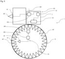
- a single overspeed sensor for example the first overspeed sensor 20, can be the only overspeed sensor included in the overspeed detection device 2 and the first overspeed sensor can comprise thirty mobile elements distributed over the wheel motor 120 as shown in figure 5 .
- the signal converter 200 which must process slow signals, is thus capable of transcribing according to an analog signal a predefined number, namely according to our example thirty, of flip-flops between the complete state and the incomplete state during a rotation complete with the drive wheel.
- the first overspeed sensor 20 changes state between the incomplete state and the complete state every twelve degrees.
- Multiplying the number of mobile elements 20" and therefore the number of switches of the first overspeed sensor 20 between the incomplete state and the complete state thus has the advantage of improving the reaction of the overspeed detection device, as said previously, the drive wheel rotating at a relatively low rotation speed and the fact that no reduction between the electric motor 122 and the drive wheel 120 is installed, the switches between the complete state and the incomplete state.
- of the first overspeed sensor are made, thanks to the use of thirty moving elements, at a frequency of 7.8Hz at one kilometer per hour for example, and therefore over a period of 128 milliseconds.
- the detection device. overspeed to have a rapid reaction time, that is to say less than 300 milliseconds, which is advantageously the case when the first overspeed sensor 20 comprises thirty mobile elements 20".
- a filter 240 in the first overspeed sensor 20 at the output of the signal converter 200 is added.
- the filter 240 is arranged between the signal converter 200 and the speed comparator 24.
- the filter at the output of the signal converter 200 must be dimensioned to be able to produce a sufficiently smooth voltage for the speed comparator 24 to be able to perform a comparison while impacting as little as possible the time linked to providing the speed measurement of the drive wheel 120 and to the comparison between the measurement of the rotation speed of the drive wheel 120 and the maximum rotation speed of the drive wheel 120 authorized.
- the filter 240 is a third-order filter.
- the filter 240 can be a filter composed of an RC low pass filter, composed of a resistor and a capacitor, of 1st order cascaded with an active Sallen Key filter.
- the Sallen Key filter can be replaced by two 1st order RC low pass filters or by a 2nd order LC passive filter, composed of a coil and a capacitor, for example.
- the overspeed detection device 2 may also include a generalized malfunction detector 29 of the first overspeed sensor 20, the second overspeed sensor 26 and the third overspeed sensor 28, as shown in Figure 4 , intended to detect a simultaneous operating fault of the first overspeed sensor 20 and the second overspeed sensor 26 or the second overspeed sensor 26 and the third overspeed sensor 28 or the first overspeed sensor 20 and the third overspeed sensor 28 or else the first overspeed sensor 20, the second overspeed sensor 26 and the third overspeed sensor 28.
- a generalized malfunction detector 29 of the first overspeed sensor 20, the second overspeed sensor 26 and the third overspeed sensor 28, as shown in Figure 4 intended to detect a simultaneous operating fault of the first overspeed sensor 20 and the second overspeed sensor 26 or the second overspeed sensor 26 and the third overspeed sensor 28 or the first overspeed sensor 20 and the third overspeed sensor 28 or else the first overspeed sensor 20, the second overspeed sensor 26 and the third overspeed sensor 28.
- the generalized operating fault detector 29 detects that two overspeed sensors are not operating correctly then the generalized operating fault detector informs the user of degraded operation of the overspeed detection device 2. And when the detector generalized malfunction detector 29 detects that the three overspeed sensors 20, 26 and 28 are not functioning correctly then the generalized malfunction detector informs the user of a malfunction of the overspeed detection device 2.
- first overspeed sensor 20, the second overspeed sensor 26 and/or the third overspeed sensor 28 may be hall effect sensors. These sensors have a simple architecture and are very easily incorporated into the wheel 12 motor assembly.
- each overspeed sensor delivering a binary signal
- the generalized malfunction detector 29 to generate a simultaneous detection of the state of each overspeed sensor among the first overspeed sensor 20, the second overspeed sensor 26 and the third overspeed sensor 28.
- the fault detector generalized operation informs the user of a malfunction of the overspeed detection device 2.
- the generalized operating fault detector 29 thus makes it possible to prevent a common cause failure which leads to the loss of the entire monitoring function of the overspeed of the vehicle 1.
- the signals from each of the first, second and third hall effect overspeed sensors are phase shifted to know approximately the position angle of the electric motor 122.
- Each hall effect overspeed sensor among the first, the second and the third overspeed sensor can give a binary signal, which includes eight possible combinations. However, only six signal combinations are possible for a desired arrangement of the first, second and third hall effect overspeed sensors. Therefore, the generalized operating fault detector 29 makes it possible to determine if one of the two “impossible” combinations is obtained and reflects the fault of an overspeed sensor among the first overspeed sensor 20, the second overspeed sensor 26 or the third overspeed sensor 28.
- first overspeed sensor 20, the second overspeed sensor 26 and/or the third overspeed sensor 28 may be rotary sensors or optical sensors.
- the invention works for an electric motor 10 commonly called in the Anglo-Saxon literature: "in wheel”, that is to say an motor directly connected to a driving wheel itself driven by the electric motor 122.
- in wheel that is to say an motor directly connected to a driving wheel itself driven by the electric motor 122.
- a vehicle 1 may comprise this type of wheel motor assembly 12 and overspeed detection device 2 may be an autonomous vehicle such as for example a robot or an autonomous delivery robot or even a remotely controlled vehicle such as a controlled delivery robot .
- the invention thus has the advantage of making it possible to detect overspeed on the part of the autonomous mobile vehicle during its movement in its movement zone as a function of its immediate environment by the coupled use of a sensor positioned directly in the drive wheel. and a lidar-type sensory sensor making it possible to stop the vehicle 1 when the situation seems critical.
Landscapes
- Engineering & Computer Science (AREA)
- Physics & Mathematics (AREA)
- General Physics & Mathematics (AREA)
- Radar, Positioning & Navigation (AREA)
- Computer Networks & Wireless Communication (AREA)
- Electromagnetism (AREA)
- Remote Sensing (AREA)
- Mechanical Engineering (AREA)
- Transportation (AREA)
- Power Engineering (AREA)
- Robotics (AREA)
- Electric Propulsion And Braking For Vehicles (AREA)
- Control Of Electric Motors In General (AREA)
Abstract
L'invention concerne un véhicule (1) comprenant un châssis (10) et un ensemble moteur roue (12) comprenant une roue motrice (120) et un moteur électrique (122) entraînant, le véhicule (1) comprenant un dispositif de détection de survitesse (2), le dispositif de détection de survitesse (2) comprenant un premier capteur (20), le premier capteur (20) étant configuré pour mesurer une vitesse de rotation,
le dispositif de détection de survitesse (2) comprenant un dispositif de référence de vitesse (22) pour établir une vitesse de rotation maximale, le dispositif de référence (22) comprenant un capteur optique (220) pour déterminer un environnement proche, la vitesse de rotation maximale étant fonction de l'environnement proche, d'un seuil de vitesse fonctionnel prédéfini et d'un sens de rotation,
le dispositif de détection de survitesse (2) comprenant un comparateur (24) entre la vitesse de rotation et la vitesse de rotation maximale, le comparateur (24) étant configuré pour arrêter la rotation de la roue motrice (120) si la vitesse de est supérieure à la vitesse de rotation maximale,The invention relates to a vehicle (1) comprising a chassis (10) and a wheel motor assembly (12) comprising a driving wheel (120) and an electric motor (122) driving, the vehicle (1) comprising a device for detecting overspeed (2), the overspeed detection device (2) comprising a first sensor (20), the first sensor (20) being configured to measure a rotation speed,
the overspeed detection device (2) comprising a speed reference device (22) for establishing a maximum rotation speed, the reference device (22) comprising an optical sensor (220) for determining a nearby environment, the speed of maximum rotation being a function of the nearby environment, a predefined functional speed threshold and a direction of rotation,
the overspeed detection device (2) comprising a comparator (24) between the rotation speed and the maximum rotation speed, the comparator (24) being configured to stop the rotation of the drive wheel (120) if the speed is greater than the maximum rotation speed,
le premier capteur de survitesse (20) comprenant un convertisseur de signal (200) configuré pour convertir une fréquence de bascule du premier capteur de survitesse (20) en une tension analogique.

Description
L'invention concerne le domaine des robots se déplaçant de manière autonome et, plus précisément, les robots mobiles autonomes aptes à transporter des marchandises ou des charges sur une zone de déplacement prédéfinie.The invention relates to the field of robots moving autonomously and, more precisely, autonomous mobile robots capable of transporting goods or loads over a predefined movement area.
Les robots mobiles autonomes permettant le déplacement d'objets sont spécifiquement conçus pour une conduite autonome et sûre.Autonomous mobile robots for moving objects are specifically designed for autonomous and safe driving.
Le système de sécurité de tels robots mobiles autonomes comprend des moyens pour détecter des obstacles dans une zone de déplacement prédéfinie autour du robot mobile autonome et des moyens pour amener le robot mobile autonome à un arrêt de manière sûre avant d'entrer en collision avec tout obstacle détecté dans une zone de déplacement définie.The safety system of such autonomous mobile robots includes means for detecting obstacles in a predefined movement zone around the autonomous mobile robot and means for bringing the autonomous mobile robot to a safe stop before colliding with any obstacle detected in a defined movement zone.
Une solution connue pour détecter des obstacles tout autour du robot mobile autonome est de monter deux scanneurs laser opposés l'un à l'autre aux coins d'un robot mobile typiquement rectangulaire. Chaque scanner couvre généralement un champ de vision de 270°, c'est-à-dire d'un côté du robot mobile à un autre côté pour un coin correspondant. Ainsi, les deux scanners peuvent couvrir une zone protectrice autour du robot autonome mobile.A known solution for detecting obstacles all around the autonomous mobile robot is to mount two laser scanners opposite each other at the corners of a typically rectangular mobile robot. Each scanner typically covers a 270° field of view, i.e. from one side of the mobile robot to another side for a corresponding corner. Thus, the two scanners can cover a protective zone around the mobile autonomous robot.
De manière connue, un tel type de robot autonome mobile peut également comprendre d'autres types de capteurs permettant par exemple de mesurer la vitesse du robot autonome mobile à tout instant.In known manner, such a type of mobile autonomous robot can also include other types of sensors making it possible, for example, to measure the speed of the mobile autonomous robot at any time.
Il est alors possible de pouvoir détecter, à partir des données des scanners et/ou des capteurs une potentielle situation de survitesse du robot mobile autonome qui se traduit par une situation pendant laquelle le robot mobile autonome se déplace selon une vitesse pouvant être qualifiée d'excessive notamment par rapport à sa zone de déplacement et par rapport à son environnement proche. C'est notamment le cas lorsque le robot mobile autonome se déplace à proximité d'obstacles, ce dernier doit alors adapter sa vitesse et son déplacement par rapport à son environnement proche et à ces obstacles.It is then possible to be able to detect, from the data from the scanners and/or sensors, a potential situation of overspeed of the autonomous mobile robot which results in a situation during which the autonomous mobile robot moves at a speed that can be described as excessive, particularly in relation to its travel area and in relation to its immediate environment. This is particularly the case when the autonomous mobile robot moves near obstacles, the latter must then adapt its speed and its movement in relation to its nearby environment and to these obstacles.
Tous ces capteurs et scanners sont généralement connectés à un contrôleur numérique qui analyse les données numériques de vitesse et de présence d'obstacle fournies par les différents capteurs et/ou scanners afin de contrôler les roues motrices du robot autonome mobile. Le contrôleur numérique adapte ainsi la vitesse et les trajectoires du robot mobile autonome en temps réel par rapport à l'environnement proche du robot et par rapport au danger immédiat que peuvent représenter les obstacles identifiés par les capteurs ou par les scanners.All these sensors and scanners are usually connected to a digital controller that analyzes digital speed and presence data obstacle provided by the various sensors and/or scanners in order to control the driving wheels of the mobile autonomous robot. The digital controller thus adapts the speed and trajectories of the autonomous mobile robot in real time in relation to the environment close to the robot and in relation to the immediate danger that obstacles identified by the sensors or scanners may represent.
Cependant, l'utilisation d'un tel contrôleur numérique et de tels capteurs numérique présente de nombreux inconvénients. En effet, l'utilisation d'un contrôleur numérique ou d'un encodeur numérique génère de la complexité dans l'architecture du robot mobile autonome du fait notamment de l'utilisation de moyens numériques. Outre les coûts importants d'une telle architecture, sa complexité peut entrainer des durées de réaction importantes incompatibles avec la sécurité du robot. De plus, en termes de sécurité liée à l'utilisation de tels moyens numériques pour obtenir un contrôle du mouvement et du freinage du robot autonome mobile, un contrôleur numérique présente également l'inconvénient de devoir respecter des normes de sécurité. La qualification vis-à-vis de ces normes peut être difficile à obtenir.However, the use of such a digital controller and such digital sensors has numerous drawbacks. Indeed, the use of a digital controller or a digital encoder generates complexity in the architecture of the autonomous mobile robot due in particular to the use of digital means. In addition to the significant costs of such an architecture, its complexity can lead to significant reaction times that are incompatible with the safety of the robot. Furthermore, in terms of safety linked to the use of such digital means to obtain control of the movement and braking of the mobile autonomous robot, a digital controller also has the disadvantage of having to comply with safety standards. Qualification against these standards can be difficult to obtain.
Afin d'éviter d'utiliser un architecture de type logicielle citée précédemment, il peut être envisagé de s'appuyer exclusivement sur une architecture matérielle mettant en oeuvre des composants logiques et analogiques câblés afin d'assurer la gestion de la vitesse du robot mobile dans sa zone de déplacement. En effet, la mise en oeuvre d'une architecture matérielle présente l'intérêt de répondre à des normes de sécurité différentes, moins contraignantes, en comparaison d'une architecture de type logicielle.In order to avoid using a software type architecture mentioned above, it can be considered to rely exclusively on a hardware architecture implementing wired logical and analog components in order to ensure the management of the speed of the mobile robot in its travel area. Indeed, the implementation of a hardware architecture has the advantage of meeting different, less restrictive security standards, compared to a software type architecture.
Ainsi, l'invention vise à pallier tout ou partie des problèmes cités plus haut en proposant un dispositif de détection d'une survitesse du robot mobile autonome fonctionnant exclusivement selon une logique de type matérielle et nécessitant uniquement l'utilisation d'un capteur simple positionné dans une roue motrice du robot mobile autonome ou au niveau d'un arbre entrainé par la roue et d'un capteur lidar permettant de détecter les obstacles et l'environnement proche du robot mobile autonome. Ce dispositif de détection de survitesse fonctionnant uniquement selon une architecture de type matérielle présente ainsi l'avantage d'être plus simple qu'une architecture de type logicielle, tout en répondant parfaitement aux normes de sécurité s'appliquant à ce type de système. L'invention présente également l'avantage de mettre en oeuvre un dispositif logique indépendant du contrôle moteur, ce qui assure une meilleure sécurité du véhicule.Thus, the invention aims to overcome all or part of the problems cited above by proposing a device for detecting an overspeed of the autonomous mobile robot operating exclusively according to hardware type logic and requiring only the use of a simple sensor positioned in a driving wheel of the autonomous mobile robot or at the level of a shaft driven by the wheel and a lidar sensor making it possible to detect obstacles and the environment close to the autonomous mobile robot. This overspeed detection device operating solely according to a hardware type architecture thus has the advantage of being simpler than a software type architecture, while perfectly meeting the safety standards applying to this type of system. The invention also has the advantage of implementing a logic device independent of engine control, which ensures better vehicle safety.
A cet effet, l'invention a pour objet un véhicule configuré pour se mouvoir dans une zone de déplacement, le véhicule comprenant un châssis et un ensemble moteur roue comprenant au moins une roue motrice et un moteur électrique entrainant en rotation la roue motrice, le véhicule comprenant un dispositif de détection de survitesse de la roue motrice, le dispositif de détection de survitesse comprenant un premier capteur de survitesse, le premier capteur de survitesse étant configuré pour mesurer une vitesse de rotation de la roue motrice,
- le dispositif de détection de survitesse comprenant un dispositif de référence de vitesse configuré pour établir une vitesse de rotation maximale de la roue motrice, le dispositif de référence de vitesse comprenant un capteur optique configuré pour déterminer un environnement proche de la roue motrice, le capteur optique étant disposé contre le châssis, la vitesse de rotation maximale étant au moins fonction de l'environnement proche, d'un seuil de vitesse fonctionnel prédéfini et d'un sens de rotation de la roue motrice,
- le dispositif de détection de survitesse comprenant un comparateur de vitesse entre la vitesse de rotation de la roue motrice et la vitesse de rotation maximale de la roue motrice, le comparateur de vitesse étant configuré pour arrêter la rotation de la roue motrice si la vitesse de rotation de la roue motrice est supérieure à la vitesse de rotation maximale de la roue motrice,
- le premier capteur de survitesse comprenant un convertisseur de signal configuré pour convertir une fréquence de bascule du premier capteur de survitesse en une tension analogique.
- the overspeed detection device comprising a speed reference device configured to establish a maximum rotational speed of the drive wheel, the speed reference device comprising an optical sensor configured to determine an environment close to the drive wheel, the optical sensor being arranged against the chassis, the maximum rotation speed being at least a function of the nearby environment, a predefined functional speed threshold and a direction of rotation of the drive wheel,
- the overspeed detection device comprising a speed comparator between the rotation speed of the drive wheel and the maximum rotation speed of the drive wheel, the speed comparator being configured to stop the rotation of the drive wheel if the rotation speed of the drive wheel is greater than the maximum rotation speed of the drive wheel,
- the first overspeed sensor including a signal converter configured to convert a flip frequency of the first overspeed sensor into an analog voltage.
Selon un aspect de l'invention, le premier capteur de survitesse comprend un élément fixe positionné dans de la roue motrice et au moins un élément mobile positionné selon une extrémité radiale de la roue mobile par rapport à l'axe de rotation.According to one aspect of the invention, the first overspeed sensor comprises a fixed element positioned in the driving wheel and at least one movable element positioned along a radial end of the movable wheel relative to the axis of rotation.
Selon un aspect de l'invention, le premier capteur de survitesse comprend un filtre disposé entre le convertisseur de signal et le comparateur de vitesse.According to one aspect of the invention, the first overspeed sensor comprises a filter placed between the signal converter and the speed comparator.
Selon un aspect de l'invention, le capteur optique est un capteur lidar.According to one aspect of the invention, the optical sensor is a lidar sensor.
Selon un aspect de l'invention, le capteur lidar est configuré pour générer une première cartographie de l'environnement proche, le capteur lidar comprend une deuxième entrée de programmation configuré pour programmer une zone d'attention du véhicule dans la zone de déplacement.According to one aspect of the invention, the lidar sensor is configured to generate a first map of the nearby environment, the lidar sensor comprises a second programming input configured to program an attention zone of the vehicle in the movement zone.
Selon un aspect de l'invention, le dispositif de détection de survitesse comprend un deuxième capteur de survitesse et disposé selon un angle prédéfinie par rapport au premier capteur de survitesse, le deuxième capteur de survitesse étant configuré pour mesurer une vitesse de rotation de la roue motrice.According to one aspect of the invention, the overspeed detection device comprises a second overspeed sensor and arranged at a predefined angle relative to the first overspeed sensor, the second overspeed sensor being configured to measure a rotational speed of the wheel motor.
Selon un aspect de l'invention, le premier capteur de survitesse et le deuxième capteur de survitesse sont des capteurs effet hall ou des capteurs rotatifs ou des capteurs optiques.According to one aspect of the invention, the first overspeed sensor and the second overspeed sensor are hall effect sensors or rotary sensors or optical sensors.
Selon un aspect de l'invention, le dispositif de détection de survitesse comprend un troisième capteur de survitesse et disposé selon un angle prédéfinie par rapport au premier capteur de survitesse et par rapport au deuxième capteur de survitesse, le troisième capteur de survitesse étant configuré pour mesurer une vitesse de rotation de la roue motrice.According to one aspect of the invention, the overspeed detection device comprises a third overspeed sensor and arranged at a predefined angle relative to the first overspeed sensor and relative to the second overspeed sensor, the third overspeed sensor being configured to measure the rotational speed of the driving wheel.
Selon un aspect de l'invention, le dispositif de détection de survitesse comprend un détecteur de défaut de fonctionnement généralisé du premier capteur de survitesse, du deuxième capteur de survitesse et du troisième capteur de survitesse, le détecteur de défaut de fonctionnement généralisé étant configuré pour détecter un défaut de fonctionnement simultanée du premier capteur de survitesse et du deuxième capteur de survitesse ou du deuxième capteur de survitesse et du troisième capteur de survitesse ou du premier capteur de survitesse et du troisième capteur de survitesse ou encore du premier capteur de survitesse, du deuxième capteur de survitesse et du troisième capteur de survitesse.According to one aspect of the invention, the overspeed detection device comprises a generalized malfunction detector of the first overspeed sensor, the second overspeed sensor and the third overspeed sensor, the generalized malfunction detector being configured to detect a simultaneous operating fault of the first overspeed sensor and the second overspeed sensor or the second overspeed sensor and the third overspeed sensor or the first overspeed sensor and the third overspeed sensor or even the first overspeed sensor, the second overspeed sensor and the third overspeed sensor.
Selon un aspect de l'invention, le moteur électrique est incorporé dans la roue motrice.According to one aspect of the invention, the electric motor is incorporated in the drive wheel.
L'invention sera mieux comprise et d'autres avantages apparaîtront à la lecture de la description détaillée d'un mode de réalisation donné à titre d'exemple, description illustrée par le dessin joint dans lequel :
- [
Fig.1 ] lafigure 1 représente une vue schématique d'un véhicule autonome comprenant un dispositif de détection de survitesse du véhicule selon l'invention ; - [
Fig.2 ] lafigure 2 représente une vue schématique du véhicule autonome selon un deuxième mode de configuration ; - [
Fig.3 ] lafigure 3 représente une vue schématique du véhicule autonome de lafigure 1 comprenant deux capteurs de survitesse ; - [
Fig.4 ] lafigure 4 représente une vue schématique du véhicule autonome comprenant un détecteur de défaut de fonctionnement généralisé selon l'invention ; - [
Fig.5 ] lafigure 5 représente une vue schématique du véhicule autonome comprenant une configuration préférentielle du dispositif de détection de survitesse selon l'invention.
- [
Fig.1 ] therefigure 1 represents a schematic view of an autonomous vehicle comprising a vehicle overspeed detection device according to the invention; - [
Fig.2 ] therefigure 2 represents a schematic view of the autonomous vehicle according to a second configuration mode; - [
Fig.3 ] thereFigure 3 represents a schematic view of the autonomous vehicle of thefigure 1 including two overspeed sensors; - [
Fig.4 ] therefigure 4 represents a schematic view of the autonomous vehicle comprising a generalized malfunction detector according to the invention; - [
Fig.5 ] therefigure 5 represents a schematic view of the autonomous vehicle comprising a preferred configuration of the overspeed detection device according to the invention.
Par souci de clarté, les mêmes éléments porteront les mêmes repères dans les différentes figures.For the sake of clarity, the same elements will carry the same references in the different figures.
La
Le véhicule 1 comprend un châssis 10 et un ensemble moteur roue 12. Le châssis 10 est relié à l'ensemble moteur roue 12 qui comprend une roue motrice 120 et un moteur électrique 122. Le moteur électrique 122 est piloté par un contrôleur (non représenté) délivrant au moteur un signal électrique adapté pour une consigne de vitesse donnée. Dans cet exemple de réalisation, l'ensemble moteur roue 12 est un ensemble qui comprend le moteur électrique 122 incorporé directement dans la roue motrice 120, lequel est capable de propulser le véhicule 1. Les principaux avantages d'un tel ensemble moteur roue 12 sont son encombrement réduit et le fait qu'il ne nécessite pas de transmission entre le moteur électrique 122 et la roue motrice 120. La roue motrice 120 est alors entraînée en rotation directement par le moteur électrique 120 selon un axe de rotation A1.The vehicle 1 comprises a
En variante, le moteur électrique 122 est au niveau d'un arbre entrainé par la roue motrice 120. Le fait de dissocier le moteur électrique 122 de la roue motrice 120 présente l'avantage de permettre au moteur électrique 122 d'entraîner plusieurs roues motrices par le biais de l'arbre d'entraînement.Alternatively, the
Le véhicule 1 comprend également un dispositif de détection de survitesse 2 de la roue motrice 120. Le dispositif de détection de survitesse 2 est configuré pour détecter lorsque le véhicule 1 est en situation de survitesse dans sa zone de déplacement. Pour ce faire, le dispositif de détection de survitesse 2 comprend un premier capteur de survitesse 20 placé au niveau de la roue motrice 120. Plus précisément, le premier capteur de survitesse 20 comprend un élément fixe 20' positionné dans la roue motrice 120, ou à proximité de son axe de rotation A1, et un ou plusieurs éléments mobiles 20" positionnés selon une extrémité radiale de la roue mobile 120 par rapport à l'axe de rotation A1. L'élément fixe 20' est disposé de sorte à être immobile dans la roue motrice 120 et permet d'avoir une mesure de référence pour la rotation de la roue motrice 120. En variante, l'élément mobile 20" est fixé aléatoirement contre la roue motrice 120.The vehicle 1 also includes an
Plus précisément, lorsque l'élément mobile 20" subit une rotation complète par rapport à l'élément fixe 20' traduisant une rotation complète de la roue motrice 120 sur elle-même, le capteur de survitesse 20 détecte alors cette rotation complète en basculant d'un état incomplet à un état complet. L'état incomplet du capteur de survitesse 20 traduit donc une rotation non complète de la roue motrice 120 et de l'élément mobile 20" alors que l'état complet traduit une rotation complète, c'est-à-dire à 360°, de la roue motrice 120 et de l'élément mobile 20". A la suite d'une bascule dans l'état complet, le premier capteur de survitesse 20 bascule à nouveau dans l'état incomplet jusqu'à détecter une nouvelle rotation complète de la roue motrice 120. Le premier capteur de survitesse 20 est alors configuré pour mesurer une vitesse de rotation de la roue motrice 120. L'élément fixe 20' du premier capteur de survitesse 20 est positionné par rapport à un référentiel défini, par exemple à proximité de l'extrémité de la roue motrice 120 selon un angle connu. Dès lors, il est possible pour le capteur de survitesse 20 de mesurer un angle de rotation de la roue motrice 120 pendant la rotation de la roue motrice 120 ou encore un angle de rotation de l'élément mobile 20" par rapport à l'élément fixe 20' du capteur de survitesse 20. En variante, le référentiel peut être un point quelconque comme le point de contact entre la roue motrice 120 et l'interface sur laquelle se déplace la roue motrice 120.More precisely, when the
L'élément fixe 20' et le ou les éléments mobiles 20" sont préférentiellement disposés de sorte à être à une faible distance l'un de l'autre afin d'améliorer la détection du premier capteur de survitesse. Et, selon une variante idéale, le ou les éléments mobiles 20" sont disposés le plus proche possible de l'élément fixe 20' sans que l'élément fixe 20' ne soit en contact avec le ou l'un des éléments mobiles 20". A titre d'exemple indicatif, l'élément fixe 20' est distant du ou des éléments mobiles d'une distance inférieure à 15 millimètres.The fixed element 20' and the movable element(s) 20" are preferably arranged so as to be at a short distance from each other in order to improve the detection of the first overspeed sensor. And, according to an ideal variant , the movable element(s) 20" are arranged as close as possible to the fixed element 20' without the fixed element 20' being in contact with the movable element(s) 20". indicative, the fixed element 20' is distant from the movable element(s) by a distance of less than 15 millimeters.
Dès lors, il est également possible de connaitre précisément le nombre de rotation complète que la roue motrice 120 a effectué et, en connaissant la durée pendant laquelle la roue motrice 120 est en mouvement, il est également possible pour le capteur de survitesse 20 de mesurer la vitesse de rotation de la roue motrice 120 en temps réel. Le capteur de survitesse 20 agit donc comme un capteur de position angulaire de l'élément mobile 20" par rapport à l'élément fixe 20' et par rapport au référentiel défini et comme un capteur de vitesse de rotation par l'intermédiaire de la mesure de la fréquence de bascule de l'état incomplet à l'état complet du capteur de survitesse 20.From then on, it is also possible to know precisely the number of complete rotations that the
Le dispositif de détection de survitesse 2 comprend également un dispositif de référence de vitesse 22 configuré pour établir une vitesse de rotation maximale de la roue motrice 120. Le dispositif de référence de vitesse 22 assure la fonction de sécurisation de la rotation de la roue motrice 120 et permet de définir les limites matérielles et fonctionnelles de la roue motrice 120 lorsque la roue motrice 120 est en mouvement. Pour ce faire, le dispositif de référence de vitesse 22 comprend un capteur lidar 220 configuré pour déterminer un environnement proche de la roue motrice 120. Le capteur lidar 220 est fixé au châssis 10 de sorte à être pouvoir émettre une onde lumineuse dans une direction prédéfinie de manière continue. De manière avantageuse, le capteur lidar 220 émet une onde lumineuse dans une direction de mouvement du véhicule 1 de sorte à permettre au capteur lidar 220 de détecter suffisamment rapidement tout obstacle se présentant au-devant du véhicule 1 et pouvant générer un accident.The
De manière avantageuse, le dispositif de référence de vitesse 22 peut comprendre plusieurs capteurs lidars 220 orientés dans différentes directions de sorte à pouvoir effectuer une cartographie plus complète de l'environnement proche du véhicule 1.Advantageously, the
En effet, l'environnement proche du véhicule 1 est défini comme la zone à proximité du véhicule 1 soumise aux ondes lumineuses du capteur lidar 220. L'environnement proche est donc une zone proche et accessible au véhicule 1 comprise dans la zone de déplacement du véhicule et cartographiée par le capteur lidar 220.Indeed, the environment close to the vehicle 1 is defined as the area near the vehicle 1 subjected to the light waves of the
L'environnement proche peut également être interprété comme la zone critique du véhicule 1 dans laquelle il est possible que le véhicule 1 rencontre un obstacle pendant son mouvement et identifiable par le capteur lidar 220. La notion de proximité peut également être interprétée comme une distance entre un objet identifié par le capteur lidar 220 et le véhicule 1 assez faible pour risquer une collision. L'environnement proche dépend notamment de la vitesse de rotation de la roue motrice 120.The nearby environment can also be interpreted as the critical zone of the vehicle 1 in which it is possible that the vehicle 1 encounters an obstacle during its movement and identifiable by the
Dès lors, afin d'empêcher toute collision non souhaité entre le véhicule 1 et un potentiel obstacle, le dispositif de référence de vitesse 22 permet d'établir une vitesse de rotation maximale de la roue motrice 120 afin de limiter la vitesse de déplacement du véhicule lorsque l'environnement proche du véhicule 1 identifié par le capteur lidar 220 présente des obstacles susceptibles d'induire à des collisions.Therefore, in order to prevent any unwanted collision between the vehicle 1 and a potential obstacle, the
La vitesse de rotation maximale de la roue motrice 120 est alors une vitesse calculée par le dispositif de référence de vitesse 22 en fonction de l'environnement proche, d'un seuil de vitesse fonctionnel prédéfini et d'un sens de rotation de la roue. Plus précisément, le seuil de vitesse fonctionnel défini la vitesse maximale à laquelle le véhicule 1 peut fonctionnellement se déplacer et remplir la fonction pour laquelle le véhicule 1 a été définie.The maximum rotation speed of the
A titre d'exemple indicatif, lorsque le capteur lidar 220 détecte dans l'environnement proche un potentiel obstacle risquant une collision avec le véhicule, alors le dispositif de référence de vitesse 22 établit une vitesse de rotation maximale de la roue motrice 120 faible. Le dispositif de référence peut également établir une vitesse maximale de rotation de la roue motrice 120 plus faible lorsque le véhicule 1 est chargé et que le seuil de vitesse fonctionnel est plus faible.As an indicative example, when the
La vitesse maximale de rotation est une vitesse indicative. En effet, la vitesse maximale de rotation doit être interprétée comme la vitesse à laquelle la roue motrice 120 doit se déplacer afin de respecter les informations liées à son environnement proche et à son fonctionnement. La vitesse maximale de rotation de la roue motrice est donc une référence de vitesse qui fluctue en temps réel en fonction des paramètres cités précédemment.The maximum rotation speed is an indicative speed. Indeed, the maximum rotation speed must be interpreted as the speed at which the
Le dispositif de détection de survitesse 2 comprend également un comparateur de vitesse 24 configuré pour comparer la vitesse de rotation de la roue motrice 120 et la vitesse de rotation maximale de la roue motrice 120 établie par le dispositif de référence de vitesse 22. Le comparateur de vitesse 24 est également configuré pour arrêter la rotation de la roue motrice 120 si la vitesse de rotation de la roue motrice 120 est supérieure à la vitesse de rotation maximale de la roue motrice 120 établie par le dispositif de référence de vitesse 22.The
Ainsi, lorsque la vitesse de rotation de la roue motrice 120 est supérieure à la vitesse maximale de rotation établie par le dispositif de référence de vitesse 22, alors le véhicule 1 se déplace trop rapidement par rapport à son environnement proche et il y a un risque important d'une collision entre un obstacle identifié ou non par le capteur lidar 220 et le véhicule 1. Le comparateur de vitesse 24 agit alors directement sur le moteur électrique 122 pour freiner le moteur électrique 122 et la roue motrice 120. De manière avantageuse, le comparateur de vitesse 24 peut également agir sur le moteur électrique 122 pour arrêter la roue motrice 120. Le comparateur de vitesse 24 permet ainsi d'agir comme une sécurité contre une potentielle situation de survitesse de la roue motrice 120 et du véhicule 1 en arrêtant la rotation de la roue motrice 120.Thus, when the rotation speed of the
Une telle réalisation permet avantageusement au comparateur de vitesse 24 d'assurer une fonction de sécurité en cas de survitesse, par exemple due à une défaillance du contrôleur.Such an embodiment advantageously allows the
Afin de mesurer plus facilement la rotation de la roue motrice 120 et la vitesse de rotation de la roue motrice 120, le premier capteur de survitesse 20 peut comprendre un convertisseur de signal 200, comme représenté en
L'utilisation du dispositif de détection de survitesse 2, et plus particulièrement du premier capteur de survitesse 20, du comparateur de vitesse 24 et du convertisseur de signal 200 présente ainsi l'avantage de dissocier la gestion de la vitesse du véhicule et de la roue motrice 120 et de la gestion générale du véhicule autonome par le contrôleur. Le dispositif de détection de survitesse 2 comprend ainsi un ensemble de composants simples ou portes logiques comme le convertisseur de signal 200 fonctionnant de façon dissociée par rapport au contrôleur qui comprend des composants numériques et complexes. Le dispositif de détection de survitesse 2 est donc un système simple et fiable pour permettre la gestion de la vitesse du véhicule autonome par rapport au contrôleur numérique et faillible. La détection d'une survitesse est donc indépendante du fonctionnement du véhicule autonome et particulièrement du contrôleur numérique.The use of the
En variante, le capteur de survitesse 20 peut également être configuré pour mesurer un angle de rotation entre l'élément mobile 20" et l'élément fixe 20'. En effet, lorsque la vitesse de rotation de la roue motrice 120 est faible, la fréquence de bascule du capteur de survitesse 20 est également faible et il devient alors difficile de mesurer cette vitesse de rotation. La connaissance de cet angle de rotation permet alors de mesurer la vitesse de rotation de la roue motrice 120 sans détecter une rotation complète de la roue motrice 120. Le convertisseur de signal 200 peut également permettre de mesurer cet angle de rotation par l'intermédiaire d'un signal créneau par exemple ou de tout autre signal périodique ou encore périodique de fréquence proportionnelle à la vitesse de rotation du moteur électrique 120.Alternatively, the
Autrement dit, le premier capteur de survitesse 20 permet de mesurer une rotation complète ou un angle de rotation de la roue motrice 120 et la vitesse de rotation de la roue motrice 120 par l'intermédiaire de la fréquence de bascule du premier capteur de survitesse 20 entre l'état incomplet et complet.In other words, the first
Le capteur lidar 220 est ainsi configuré pour identifier ou représenter numériquement l'environnement proche du véhicule 1 par le biais d'une première cartographie 222. Le capteur lidar 220 permet, par cette première cartographie 222, de scanner l'environnement proche et de savoir où sont les objets dans son champ de vision et à quelle distance par rapport au véhicule 1.The
Il peut également être envisagé de programmer, dans le capteur lidar 220 par le biais d'une deuxième entrée de programmation 224, une zone d'attention du véhicule 1 dans la première cartographie 222. La programmation de cette zone d'attention permet à un utilisateur de définir, dans la zone de déplacement du véhicule 1, des zones dans lesquelles le véhicule 1 ne doit pas se mouvoir ou doit se mouvoir selon des vitesses restreintes. Ces zones d'attention peuvent ainsi être interprétées comme des zones critiques où une collision est fortement envisagée.It can also be envisaged to program, in the
II est ainsi possible d'obtenir une première cartographie plus précise combinant le scan du capteur lidar 220 et la programmation des zones d'attention par le biais de la deuxième entrée de programmation 224 du capteur lidar 220. La programmation de la ou des zones d'attention peut également se faire en amont d'un déplacement du véhicule 1 ou pendant le déplacement du véhicule 1 dans sa zone de déplacement.It is thus possible to obtain a first, more precise mapping combining the scan of the
Il peut également être envisagé de remplacer le capteur lidar 220 par un autre capteur optique ou de proximité comme un sonar, un capteur ToF ou encore une caméra.It can also be considered to replace the
Ainsi, à partir de la première cartographie 222 complétée ou non par la deuxième entrée de programmation 224, le dispositif de référence de vitesse 22 établit la vitesse de rotation maximale de la roue motrice 120. Comme énoncé précédemment, le dispositif de référence de vitesse peut également prendre en considération d 'autres paramètres d'entrée comme les limites matérielles du véhicule 1.Thus, from the
De manière avantageuse, le dispositif de détection de survitesse 2 peut comprendre un deuxième capteur de survitesse 26, comme représenté en
L'utilisation d'un deuxième capteur de survitesse 26 présente ainsi l'avantage d'obtenir de données liées à la rotation de la roue motrice 120 apportant une redondance vis à vis des données mesurées par le premier capteur de survitesse 20 . Le deuxième capteur de survitesse 26 présente également l'avantage de permettre de mesurer une vitesse de rotation de la roue sans nécessiter de rotation complète de la roue motrice 120.The use of a second
En effet, le véhicule 1 se déplace généralement à des vitesses relativement faibles, inférieures à trois kilomètres par heure. Dès lors, le temps nécessaire pour obtenir une première donnée quantifiable de la vitesse de rotation de la roue motrice 120 peut généralement nécessiter un délai relativement long. Or, pendant ce délai de mesure de la vitesse de rotation, l'environnement proche du véhicule 1 peut facilement changer et un obstacle dans l'environnement proche peut apparaitre au-devant du véhicule, transformant une situation de fonctionnement nominal du véhicule 1 en une potentielle situation de collision dangereuse. L'utilisation d'un deuxième capteur de survitesse 26 selon un angle prédéfinie par rapport au premier capteur de survitesse 20 permet ainsi de limiter la durée nécessaire pour la mesure de la rotation de la roue motrice 120 et de sa vitesse de rotation puisque cette mesure est données lorsque l'angle entre le premier capteur de survitesse 20 et le deuxième capteur de survitesse 26 est complété.Indeed, vehicle 1 generally moves at relatively low speeds, less than three kilometers per hour. Therefore, the time necessary to obtain a first quantifiable data of the rotation speed of the
Afin de permettre la mesure la plus précise possible de la vitesse de rotation de la roue motrice 120, le dispositif de détection de survitesse 2 peut comprendre un troisième capteur de survitesse 28 également fixé à la roue motrice 120 et disposé selon un angle prédéfinie par rapport au premier capteur de survitesse 20 et par rapport au deuxième capteur de survitesse 26. De manière similaire au premier capteur de survitesse 20 et au deuxième capteur de survitesse 26, le troisième capteur de survitesse 28 comprend un élément fixe 28' du troisième capteur de survitesse 28 positionné à proximité de l'axe de rotation A1 de la roue motrice 120 et un élément mobile 28" du troisième capteur de survitesse 28 positionné selon une extrémité radiale de la roue mobile 120 par rapport à l'axe de rotation A1, l'élément mobile 28" du troisième capteur de survitesse 28 étant disposé selon un angle prédéfini par rapport à l'élément mobile 20" du premier capteur de survitesse 20 et par rapport à l'élément mobile 26" du deuxième capteur de survitesse 26. Le troisième capteur de survitesse est également configuré pour mesurer une vitesse de rotation de la roue motrice 120. Autrement dit, le troisième capteur de survitesse 28 permet de mesurer une rotation complète ou un angle de rotation de la roue motrice 120 et la vitesse de rotation de la roue motrice 120 par l'intermédiaire d'une fréquence de bascule du troisième capteur de survitesse 28 entre l'état incomplet et complet.In order to allow the most precise measurement possible of the rotational speed of the
L'utilisation de trois capteurs de survitesse 20, 26 et 28 présente ainsi l'avantage de permettre une répartition angulaire uniforme dans la roue motrice 120 sans encombrer l'ensemble moteur roue 12. En outre, si un capteur de survitesse parmi le premier capteur de survitesse 20, le deuxième capteur de survitesse 26 ou le troisième capteur de survitesse 28 ne fonctionne pas correctement, le dispositif de détection de survitesse 2 ne s'en trouve pas impacté dans sa mesure de la vitesse de rotation de la roue motrice 120. La multiplication de capteurs de survitesse permet également de répondre à une exigence de redondance en termes de sécurité.The use of three
Selon une variante préférentielle, il peut être envisagé que le premier capteur de survitesse 20, le deuxième capteur de survitesse 26 et le troisième capteur de survitesse 28 partagent un même et unique élément fixe, à savoir par exemple l'élément fixe 20' du premier capteur de survitesse 20 et comprennent chacun un nombre prédéfini d'éléments mobiles, de sorte que le dispositif de détection de survitesse 2 comprenne une somme prédéfinies d'éléments mobiles répartis uniformément sur la roue motrice 120. A titre d'exemple indicatif, chaque capteur de survitesse peut comprendre dix éléments mobiles de sorte que le dispositif de détection de survitesse 2 comprenne trente éléments mobiles répartis uniformément sur la roue motrice 120According to a preferred variant, it can be envisaged that the first
En variante idéale, un seul capteur de survitesse, par exemple le premier capteur de survitesse 20, peut être le seul capteur de survitesse compris dans le dispositif de détection de survitesse 2 et le premier capteur de survitesse peut comprendre trente éléments mobiles répartis sur la roue motrice 120 comme représenté en
Dès lors, le convertisseur de signal 200, qui doit traiter des signaux lents, est ainsi capable transcrire selon un signal analogique un nombre prédéfini, à savoir selon notre exemple trente, de bascules entre l'état complet et l'état incomplet pendant une rotation complète de la roue motrice. En effet, le premier capteur de survitesse 20 change d'état entre l'état incomplet et l'état complet tous les douze degrés.Therefore, the
La multiplication du nombre d'élément mobile 20" et donc du nombre de bascule du premier capteur de survitesse 20 entre l'état incomplet et l'état complet présente ainsi l'avantage d'améliorer la réaction du dispositif de détection de survitesse, comme dis précédemment. En effet, la roue motrice tournant à une vitesse de rotation relativement faible et le fait qu'aucune réduction entre le moteur électrique 122 et la roue motrice 120 ne soit installé, les bascules entre l'état complet et l'état incomplet du premier capteur de survitesse se font, grâce à l'utilisation de trente éléments mobiles, à une fréquence de 7.8Hz à un kilomètre par heure par exemple, et donc selon une période de 128 millisecondes. Or il est nécessaire pour le dispositif de détection de survitesse d'avoir un temps de réaction rapide, c'est-à-dire inférieur à 300 millisecondes, ce qui est avantageusement le cas lorsque le premier capteur de survitesse 20 comprend trente éléments mobile 20".Multiplying the number of
Il peut également être envisagé d'ajouter un filtre 240 dans le premier capteur de survitesse 20 en sortie du convertisseur de signal 200. Le filtre 240 est disposé entre le convertisseur de signal 200 et le comparateur de vitesse 24. Le filtre en sortie de convertisseur de signal 200 doit être dimensionné pour pouvoir produire une tension suffisamment lisse pour que le comparateur de vitesse 24 puisse effectuer une comparaison tout en impactant le moins possible le temps lié à la fourniture de la mesure de vitesse de la roue motrice 120 et à la comparaison entre la mesure de la vitesse de rotation de la roue motrice 120 et la vitesse de rotation maximale de la roue motrice 120 autorisée.It can also be envisaged to add a
Selon une configuration préférentielle, le filtre 240 est un filtre de troisième ordre.According to a preferred configuration, the
A titre d'exemple indicatif, le filtre 240 peut être un filtre composé d'un filtre passe bas RC, composé d'une résistance et d'un condensateur, de 1er ordre cascadé avec un filtre actif de sallen key. En variante, le filtre sallen key peut être remplacé par deux filtres passe bas RC de 1 er ordre ou par un filtre passif du 2nd ordre LC, composé d'une bobine et d'un condensateur, par exemple.As an indicative example, the
Le dispositif de détection de survitesse 2 peut également comprendre un détecteur de défaut de fonctionnement généralisé 29 du premier capteur de survitesse 20, du deuxième capteur de survitesse 26 et du troisième capteur de survitesse 28, comme représenté en
Ainsi, lorsque le détecteur de défaut de fonctionnement généralisé 29 détecte que deux capteurs de survitesse ne fonctionnent pas correctement alors le détecteur de défaut de fonctionnement généralisé informe l'utilisateur d'un fonctionnement dégradé du dispositif de détection de survitesse 2. Et lorsque le détecteur de défaut de fonctionnement généralisé 29 détecte que les trois capteurs de survitesse 20, 26 et 28 ne fonctionnent pas correctement alors le détecteur de défaut de fonctionnement généralisé informe l'utilisateur d'un disfonctionnement du dispositif de détection de survitesse 2.Thus, when the generalized
En outre, le premier capteur de survitesse 20, le deuxième capteur de survitesse 26 et/ou le troisième capteur de survitesse 28 peuvent être des capteurs à effet hall. Ces capteurs présentent une architecture simple et sont très facilement incorporables dans l'ensemble moteur roue 12.In addition, the first
A titre d'exemple indicatif, chaque capteur de survitesse délivrant un signal binaire, il est possible pour le détecteur de défaut de fonctionnement généralisé 29 de générer une détection simultanée de l'état de chaque capteur de survitesse parmi le premier capteur de survitesse 20, le deuxième capteur de survitesse 26 et le troisième capteur de survitesse 28. Et, lorsque le premier capteur de survitesse 20, le deuxième capteur de survitesse 26 et le troisième capteur de survitesse 28 affichent le même état de manière simultanée alors le détecteur de défaut de fonctionnement généralisé informe l'utilisateur d'un disfonctionnement du dispositif de détection de survitesse 2. Le détecteur de défaut de fonctionnement généralisé 29 permet ainsi de prévenir d'une défaillance de cause commune qui induit à la perte de la totalité de la fonction de surveillance de la survitesse du véhicule 1. Plus précisément, selon une configuration avec trois capteurs de survitesse 20, 26 et 28 à effet halls, les signaux de chacun des premier, deuxième et troisième capteurs de survitesse à effet hall sont déphasés pour connaître approximativement la position angulaire du moteur électrique 122. Chaque capteur de survitesse à effet hall parmi le premier, le deuxième et le troisième capteur de survitesse, peut donner un signal binaire, ce qui comptabilise huit combinaisons possibles. Or, seulement six combinaisons de signaux sont possibles pour un arrangement souhaité des premier, deuxième et troisième capteurs de survitesse à effet hall. Dès lors, le détecteur de défaut de fonctionnement généralisé 29 permet de déterminer si l'une des deux combinaisons « impossibles » est obtenues et traduit le défaut d'un capteur de survitesse parmi le premier capteur de survitesse 20, le deuxième capteur de survitesse 26 ou le troisième capteur de survitesse 28.As an indicative example, each overspeed sensor delivering a binary signal, it is possible for the
En variante, le premier capteur de survitesse 20, le deuxième capteur de survitesse 26 et/ou le troisième capteur de survitesse 28 peuvent être des capteurs rotatifs ou des capteurs optiques.Alternatively, the first
De manière avantageuse, l'invention fonctionne pour un moteur électrique 10 communément appelé dans la littérature anglosaxonne : « in wheel », c'est-à-dire un moteur directement relié à une roue motrice entraînée elle-même pas le moteur électrique 122. Néanmoins, il peut aisément être envisagé par l'Homme du métier d'ajouter un organe intermédiaire pour, par exemple modifier la force et/ou le couple généré par le moteur électrique comme un réducteur par exemple. Un véhicule 1 peut comprenant ce type d'ensemble moteur roue 12 et de dispositif de détection de survitesse 2 peut être un véhicule autonome comme par exemple un robot ou un robot de livraison autonome ou encore un véhicule télécommandé à distance comme un robot de livraison commandé.Advantageously, the invention works for an
L'invention présente ainsi l'avantage de permettre de détecter une survitesse de la part du véhicule mobile autonome pendant son déplacement dans sa zone de déplacement en fonction de son environnement proche par l'utilisation couplée d'un capteur positionné directement dans la roue motrice et d'un capteur sensoriel de type lidar permettant d'arrêter le véhicule 1 lorsque la situation semble critique.The invention thus has the advantage of making it possible to detect overspeed on the part of the autonomous mobile vehicle during its movement in its movement zone as a function of its immediate environment by the coupled use of a sensor positioned directly in the drive wheel. and a lidar-type sensory sensor making it possible to stop the vehicle 1 when the situation seems critical.
Claims (10)
Applications Claiming Priority (1)
| Application Number | Priority Date | Filing Date | Title |
|---|---|---|---|
| FR2211515A FR3141634A1 (en) | 2022-11-04 | 2022-11-04 | Overspeed detection device |
Publications (1)
| Publication Number | Publication Date |
|---|---|
| EP4364904A1 true EP4364904A1 (en) | 2024-05-08 |
Family
ID=85017888
Family Applications (1)
| Application Number | Title | Priority Date | Filing Date |
|---|---|---|---|
| EP23206669.6A Pending EP4364904A1 (en) | 2022-11-04 | 2023-10-30 | Overspeed detection device |
Country Status (4)
| Country | Link |
|---|---|
| US (1) | US20240149702A1 (en) |
| EP (1) | EP4364904A1 (en) |
| JP (1) | JP2024068176A (en) |
| FR (1) | FR3141634A1 (en) |
Citations (3)
| Publication number | Priority date | Publication date | Assignee | Title |
|---|---|---|---|---|
| KR100585680B1 (en) * | 2004-12-10 | 2006-06-07 | 엘지전자 주식회사 | Driving wheel velocity command value creation method for mobile robot |
| US20150183432A1 (en) * | 2012-06-21 | 2015-07-02 | Remote Control Technologies Pty Ltd | Speed control system |
| WO2022134863A1 (en) * | 2020-12-25 | 2022-06-30 | 优必选北美研发中心公司 | Anticollision method, mobile machine and storage medium |
-
2022
- 2022-11-04 FR FR2211515A patent/FR3141634A1/en active Pending
-
2023
- 2023-10-30 EP EP23206669.6A patent/EP4364904A1/en active Pending
- 2023-10-30 US US18/385,301 patent/US20240149702A1/en active Pending
- 2023-11-02 JP JP2023188224A patent/JP2024068176A/en active Pending
Patent Citations (3)
| Publication number | Priority date | Publication date | Assignee | Title |
|---|---|---|---|---|
| KR100585680B1 (en) * | 2004-12-10 | 2006-06-07 | 엘지전자 주식회사 | Driving wheel velocity command value creation method for mobile robot |
| US20150183432A1 (en) * | 2012-06-21 | 2015-07-02 | Remote Control Technologies Pty Ltd | Speed control system |
| WO2022134863A1 (en) * | 2020-12-25 | 2022-06-30 | 优必选北美研发中心公司 | Anticollision method, mobile machine and storage medium |
Also Published As
| Publication number | Publication date |
|---|---|
| US20240149702A1 (en) | 2024-05-09 |
| FR3141634A1 (en) | 2024-05-10 |
| JP2024068176A (en) | 2024-05-17 |
Similar Documents
| Publication | Publication Date | Title |
|---|---|---|
| FR2593765A1 (en) | ELECTRIC DIRECTION SYSTEM FOR VEHICLES | |
| WO2015033034A1 (en) | Control interface with haptic feedback | |
| FR2585996A1 (en) | ELECTRIC DIRECTION SYSTEM FOR VEHICLES | |
| FR2585998A1 (en) | ELECTRIC DIRECTION SYSTEM FOR VEHICLES | |
| EP0194930B1 (en) | Electro-optic torque-measuring device for an actuating mechanism | |
| CA2742643A1 (en) | Autonomous moving device for aircraft | |
| EP0522949A1 (en) | Proximity detector | |
| FR2484887A1 (en) | POSITIONING APPARATUS FOR REWINDING A ROTATING TABLE TO ROTATE | |
| FR2608273A1 (en) | METHOD FOR DETERMINING THE ROTATION ANGLE OF A ROTATING BODY | |
| FR2854110A1 (en) | Rotational driving apparatus for moving headlight`s optical axis, has control unit to determine whether two detected voltages of output shaft at respective detection positions are within error range | |
| EP4364904A1 (en) | Overspeed detection device | |
| FR2495797A1 (en) | Laser-optic automatic positioning for electric vehicle - uses fixed reference of three retro-reflectors and measures angle of reflected light to position vehicle | |
| CA2300577C (en) | Digital video image transmission device | |
| FR2703450A1 (en) | Absolute incremental numerical encoder, installation and machine comprising this encoder | |
| WO2002086515A1 (en) | Device for reading the rotational speed of a paint sprayer provided with a rotating bowl | |
| WO1993004255A1 (en) | Guard system for automatic doors | |
| EP0959362B1 (en) | Device for measuring a physical value related to the rotation of a body | |
| FR2480191A1 (en) | INSTALLATION FOR CONTROLLING AND MONITORING ADJUSTING DEVICES FOR PRINTING MACHINES | |
| EP2683579B1 (en) | Method and device for controlling the electric motor of a windshield wiper | |
| EP0736963B1 (en) | Process and apparatus for controlling a stepping motor | |
| FR2802495A1 (en) | STEERING DEVICE, PARTICULARLY FOR A LIFT TRUCK | |
| FR2786284A1 (en) | METHOD FOR CONTROLLING THE MOVEMENT OF A SERVO CONTROL ELEMENT | |
| WO2017006050A1 (en) | Device for detecting a neutral position of a gearshift control of a motor vehicle gearbox | |
| EP3912950B1 (en) | System for managing working modes of a mobile crane on a site | |
| FR2782689A1 (en) | RAIL VEHICLE BOGIE, PROCESS FOR MACHINING THIS BOGIE AND TOOL FOR IMPLEMENTING THIS PROCESS |
Legal Events
| Date | Code | Title | Description |
|---|---|---|---|
| PUAI | Public reference made under article 153(3) epc to a published international application that has entered the european phase |
Free format text: ORIGINAL CODE: 0009012 |
|
| STAA | Information on the status of an ep patent application or granted ep patent |
Free format text: STATUS: THE APPLICATION HAS BEEN PUBLISHED |
|
| AK | Designated contracting states |
Kind code of ref document: A1 Designated state(s): AL AT BE BG CH CY CZ DE DK EE ES FI FR GB GR HR HU IE IS IT LI LT LU LV MC ME MK MT NL NO PL PT RO RS SE SI SK SM TR |