EP4364694A2 - Oral care refill head - Google Patents
Oral care refill head Download PDFInfo
- Publication number
- EP4364694A2 EP4364694A2 EP24164077.0A EP24164077A EP4364694A2 EP 4364694 A2 EP4364694 A2 EP 4364694A2 EP 24164077 A EP24164077 A EP 24164077A EP 4364694 A2 EP4364694 A2 EP 4364694A2
- Authority
- EP
- European Patent Office
- Prior art keywords
- stem
- sleeve
- handle
- oral care
- refill head
- Prior art date
- Legal status (The legal status is an assumption and is not a legal conclusion. Google has not performed a legal analysis and makes no representation as to the accuracy of the status listed.)
- Pending
Links
- 239000000463 material Substances 0.000 claims description 30
- 230000008878 coupling Effects 0.000 claims description 15
- 238000010168 coupling process Methods 0.000 claims description 15
- 238000005859 coupling reaction Methods 0.000 claims description 15
- 230000013011 mating Effects 0.000 abstract description 3
- 210000003128 head Anatomy 0.000 description 204
- 238000004140 cleaning Methods 0.000 description 32
- 239000004033 plastic Substances 0.000 description 7
- 239000002184 metal Substances 0.000 description 6
- 229910001092 metal group alloy Inorganic materials 0.000 description 6
- 238000003780 insertion Methods 0.000 description 3
- 230000037431 insertion Effects 0.000 description 3
- 239000013536 elastomeric material Substances 0.000 description 2
- 210000000887 face Anatomy 0.000 description 2
- 230000003993 interaction Effects 0.000 description 2
- 238000000034 method Methods 0.000 description 2
- 229920001707 polybutylene terephthalate Polymers 0.000 description 2
- 238000009732 tufting Methods 0.000 description 2
- 239000002023 wood Substances 0.000 description 2
- 239000004677 Nylon Substances 0.000 description 1
- 230000001154 acute effect Effects 0.000 description 1
- 230000009286 beneficial effect Effects 0.000 description 1
- 229920001400 block copolymer Polymers 0.000 description 1
- 230000007423 decrease Effects 0.000 description 1
- 239000000835 fiber Substances 0.000 description 1
- 229920005570 flexible polymer Polymers 0.000 description 1
- 230000006872 improvement Effects 0.000 description 1
- 238000001746 injection moulding Methods 0.000 description 1
- 230000007246 mechanism Effects 0.000 description 1
- 230000004048 modification Effects 0.000 description 1
- 238000012986 modification Methods 0.000 description 1
- 210000000214 mouth Anatomy 0.000 description 1
- 229920001778 nylon Polymers 0.000 description 1
- 239000013502 plastic waste Substances 0.000 description 1
- -1 polybutylene terephthalate Polymers 0.000 description 1
- 229920005996 polystyrene-poly(ethylene-butylene)-polystyrene Polymers 0.000 description 1
- 230000008569 process Effects 0.000 description 1
- 239000012858 resilient material Substances 0.000 description 1
- 210000004872 soft tissue Anatomy 0.000 description 1
- 210000001519 tissue Anatomy 0.000 description 1
- 239000002699 waste material Substances 0.000 description 1
- XLYOFNOQVPJJNP-UHFFFAOYSA-N water Substances O XLYOFNOQVPJJNP-UHFFFAOYSA-N 0.000 description 1
Images


Classifications
-
- A—HUMAN NECESSITIES
- A46—BRUSHWARE
- A46B—BRUSHES
- A46B7/00—Bristle carriers arranged in the brush body
- A46B7/04—Bristle carriers arranged in the brush body interchangeably removable bristle carriers
- A46B7/042—Clip or snap connection for bristle carriers
-
- A—HUMAN NECESSITIES
- A61—MEDICAL OR VETERINARY SCIENCE; HYGIENE
- A61C—DENTISTRY; APPARATUS OR METHODS FOR ORAL OR DENTAL HYGIENE
- A61C17/00—Devices for cleaning, polishing, rinsing or drying teeth, teeth cavities or prostheses; Saliva removers; Dental appliances for receiving spittle
- A61C17/16—Power-driven cleaning or polishing devices
- A61C17/22—Power-driven cleaning or polishing devices with brushes, cushions, cups, or the like
- A61C17/222—Brush body details, e.g. the shape thereof or connection to handle
-
- A—HUMAN NECESSITIES
- A46—BRUSHWARE
- A46B—BRUSHES
- A46B7/00—Bristle carriers arranged in the brush body
- A46B7/04—Bristle carriers arranged in the brush body interchangeably removable bristle carriers
-
- A—HUMAN NECESSITIES
- A46—BRUSHWARE
- A46B—BRUSHES
- A46B9/00—Arrangements of the bristles in the brush body
- A46B9/02—Position or arrangement of bristles in relation to surface of the brush body, e.g. inclined, in rows, in groups
- A46B9/04—Arranged like in or for toothbrushes
-
- A—HUMAN NECESSITIES
- A61—MEDICAL OR VETERINARY SCIENCE; HYGIENE
- A61C—DENTISTRY; APPARATUS OR METHODS FOR ORAL OR DENTAL HYGIENE
- A61C17/00—Devices for cleaning, polishing, rinsing or drying teeth, teeth cavities or prostheses; Saliva removers; Dental appliances for receiving spittle
- A61C17/16—Power-driven cleaning or polishing devices
- A61C17/22—Power-driven cleaning or polishing devices with brushes, cushions, cups, or the like
- A61C17/225—Handles or details thereof
-
- A—HUMAN NECESSITIES
- A46—BRUSHWARE
- A46B—BRUSHES
- A46B2200/00—Brushes characterized by their functions, uses or applications
- A46B2200/10—For human or animal care
- A46B2200/1066—Toothbrush for cleaning the teeth or dentures
Definitions
- Toothbrushes having replaceable heads have been used for many years, enabling users to replace the head of the toothbrush for continued use with the same handle. This is often used for electric toothbrushes because the expensive electronic circuitry is stored in the handle making it cost-prohibitive to have to dispose of the handle each time that the cleaning elements on the head have worn out and require replacement.
- a replaceable head which can be beneficial to the environment, for example, because less plastic waste is being added to the landfills when only the head is being replaced every three months or so.
- connection mechanism between the handle and the replaceable heads configured to be attached thereto There is a continuing need for an improvement in the connection mechanism between the handle and the replaceable heads configured to be attached thereto.
- the present invention is directed to an oral care implement that includes a handle and an oral care refill head.
- the oral care refill head is alterable between a first state in which it is separated from the handle and a second state in which it is coupled to the handle.
- the oral care refill head has a proximal edge surface that defines an opening into a sleeve cavity.
- the proximal edge surface is inclined downwardly and away with radial distance from a cavity axis of the sleeve cavity.
- the handle has a gripping portion that terminates at a distal end and a stem that protrudes from the distal end.
- the annular shoulder that is inclined downwardly and away from a stem to facilitate mating of the oral care refill head to the handle.
- the oral care refill head may have features for securing the oral care refill head to the stem of the handle.
- the invention may be an oral care implement comprising: a handle comprising: a gripping portion having a distal end; and a stem extending along a stem axis and protruding from the distal end of the gripping portion so that the distal end of the gripping portion comprises an annular shoulder surface that circumscribes the stem, the stem comprising a stem interference section and a stem snap element; the annular shoulder surface extending radially from an outer shoulder edge to an inner shoulder edge adjacent the stem, the annular shoulder surface inclined from the inner shoulder edge to the outer shoulder edge in one direction either upwardly towards the distal end of the stem or downwardly away from the distal end of the stem with increasing distance from the stem axis; and a sleeve portion comprising a sleeve cavity extending along a cavity axis, a proximal edge surface defining an opening into the sleeve cavity, a sleeve interference section, and a sleeve snap element; and the proximal edge
- the invention may be an oral care refill head for detachable coupling to a stem of a handle, the oral care refill head comprising: an oral care treatment portion; and a sleeve portion comprising: a sleeve cavity extending along a cavity axis; a sleeve interference section configured to form an interference fit with a stem interference section of the stem; a sleeve snap element configured to snap-interlock with a stem snap element of the stem; and a proximal edge surface that defines an opening into the sleeve cavity, the proximal edge surface of the sleeve portion extending radially from an outer sleeve edge to an inner sleeve edge, the proximal edge surface inclined from the inner sleeve edge to the outer sleeve edge in one direction either upwardly towards the oral treatment portion or downwardly away from oral treatment portion with increasing distance from the cavity axis.
- the invention may be an oral care refill head for detachable coupling to a stem of a handle, the oral care refill head comprising: an oral care treatment portion comprising a front surface facing a first direction, a plurality of tooth cleaning elements protruding from the front surface; and a sleeve portion comprising: a distal end to which the oral care treatment portion is coupled; a front surface facing the first direction and a rear surface facing a second direction, the second direction opposite the first direction; a sleeve cavity extending along a cavity axis and configured to receive the stem of the handle; a proximal edge surface that defines an opening into the sleeve cavity, the proximal edge surface extending from an outer sleeve edge to an inner sleeve edge, wherein a front portion of the outer sleeve edge is located a first axial distance from the distal end of the sleeve portion and a rear portion of the outer sleeve edge of the oral care refill head compris
- the invention may be a handle for detachably coupling to an oral care refill head, the handle comprising: a gripping portion having a distal end; and a stem extending along a stem axis and protruding from the distal end of the gripping portion, the stem comprising: a stem body having an outer surface; a stem ring protruding from and extending circumferentially around the outer surface of the stem body, the stem ring configured to snap-interlock with a sleeve snap element of a sleeve portion of the oral care refill head; a stem rib that protrudes from and extends axially along an outer surface of a stem body, the stem rib intersecting the stem ring; and the stem rib protruding a first height from the outer surface of the stem body and the stem ring protruding a second height from the outer surface of the stem body, the second height being less than the first height.
- the invention may be an oral care refill head for detachable coupling to a stem of a handle, the oral care refill head comprising: an oral care treatment portion; and a sleeve portion comprising: a sleeve cavity extending along a cavity axis and configured to receive the stem of the handle; a proximal edge surface that defines an opening into the sleeve cavity, the proximal edge surface of the sleeve portion extending radially from an outer sleeve edge to an inner sleeve edge, the proximal edge surface inclined from the inner sleeve edge to the outer sleeve edge in one direction either upwardly towards the oral treatment portion or downwardly away from oral treatment portion with increasing distance from the cavity axis; and one or more features for securing the oral care refill head to the stem of the handle.
- an oral care implement 1000 is illustrated in accordance with an embodiment of the present invention.
- the oral care implement 1000 is a manual toothbrush.
- the invention is not to be so limited in all embodiments and the oral care implement 1000 can take on other structural forms, including being a powered toothbrush, a tongue scraper, a gum and soft tissue cleanser, a water pick, an interdental device, a tooth polisher, a specially designed ansate implement having tooth engaging elements, or any other type of implement that is commonly used for oral care.
- the implement may not be specifically used for oral care, but could instead be a personal care implement which includes the various types of oral care implements noted herein and also includes hairbrushes, razors, body scrubbers, skin treatment devices, or the like.
- inventive concepts discussed herein can be applied to any type of oral care implement or personal care implement unless a specific type of implement is specified in the claims.
- the oral care implement 1000 generally comprises a handle 100 and an oral care refill head 200.
- the handle 100 is the portion of the oral care implement 1000 that is gripped by a user during use of the oral care implement 1000 and the oral care refill head 200 is the portion of the oral care implement 1000 that includes a treatment portion for performing a treatment to the user, such as a cleaning of the oral cavity.
- the oral care refill head 200 is alterable between a first state in which the oral care refill head 200 is separated from the handle (as shown in FIG. 2 ) and a second state in which the oral care refill head 200 is coupled to the handle 100 (as shown in FIG. 1 ).
- the oral care refill head 200 is replaceable so that once the treatment portion thereof becomes worn, it can be replaced with a new oral care refill head by attaching the new oral care refill head to the same common handle 100. This may reduce costs and waste which consumers find desirable in today's climate.
- the handle 100 generally comprises a gripping portion 110 extending from a proximal end 111 to a distal end 112 and a stem 120 extending or protruding from the distal end 112 of the gripping portion 110.
- the gripping portion 110 of the handle 100 is the portion that is typically gripped and manipulated by a user during user of the oral care implement 1000 to perform a treatment function.
- the gripping portion 110 of the handle 100 has a round or circular/oval cross-sectional shape.
- the invention is not to be limited by this in all embodiments and the gripping portion 110 can take on any desired shape including having additional recesses, contours, or the like to enhance gripability.
- the stem 120 of the handle 100 is the portion that is used to couple the handle 100 to the oral care refill head 200, as will be described in much greater detail below.
- the stem 120 has features that facilitate the attachment of the handle 100 to the oral care refill head 200.
- the stem 120 comprises a stem body 121 having several different sections that serve different functions in achieving an acceptable coupling between the handle 110 and the oral care refill head 200.
- the stem 120 and the gripping portion 110 are integrally formed as a unitary and monolithic component in the exemplified embodiment.
- the entirety of the handle 100 is formed out of a first material.
- the first material may have a first hardness.
- the first material may be a metal or a metal alloy.
- the first material may be wood or a hard plastic.
- the gripping portion 110 and the stem 120 may be formed from different materials.
- the gripping portion 110 may be formed from metal or a metal alloy and the stem 120 may be formed from a hard plastic.
- the gripping portion 110 may be formed from a hard plastic and the stem 120 may be formed from metal or a metal alloy. In still other embodiments, the gripping portion 110 may be formed from wood and the stem 120 may be formed from metal, metal alloys, hard plastic, or combinations thereof. Thus, some variation in the material used to form the different parts of the handle 100 may be possible in some embodiments.
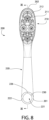
- the oral care refill head 200 comprises an oral care treatment portion and a sleeve portion 220.
- the sleeve portion 220 comprises a sleeve cavity 221 that is configured to receive at least a portion of the stem 120 of the handle 100 for purposes of coupling the oral care refill head 200 to the handle 100.
- the oral care refill head 200 extends from a proximal end 201 that is formed by a proximal edge surface 222 of the sleeve portion 220 to a distal end 202 that is formed by a terminal end of the oral care treatment portion 210.
- the oral care treatment portion 210 comprises a head body 211 located at a distal end of the sleeve portion 220.
- the head body 211 may be integrally formed with the sleeve portion 220 as a monolithic component.
- the head body 211 has a front surface 212 facing a first direction and a rear surface 213 facing a second direction that is opposite the first direction.
- the oral care treatment portion 210 also comprises a plurality of tooth cleaning elements 214 protruding from the front surface 212 of the head body 211 in the first direction.
- the plurality of tooth cleaning elements 214 comprises a plurality of bristle tufts 215 and a plurality of elastomeric cleaning elements 216.
- the bristle tufts 215 and the elastomeric cleaning elements 107 collectively form a cleaning element field on the head body 211.
- the particular arrangement and/or pattern and/or location of the various bristle tufts 215 and elastomeric cleaning elements 216 is not to be limiting of the present invention in all embodiments. Thus, the bristle tufts 215 and the elastomeric cleaning elements 216 could be positioned at locations other than that which is depicted in the drawings.
- the oral care refill head 200 may include only bristle tufts 215 and none of the elastomeric cleaning elements 216.
- various permutations of the plurality of tooth cleaning elements 214 are possible within the scope of the invention described herein.
- tooth cleaning elements may be used in a generic sense to refer to any structure that can be used to clean, polish, or wipe the teeth and/or soft oral tissue (e.g. tongue, cheek, gums, etc.) through relative surface contact.
- teeth cleaning elements include, without limitation, bristle tufts, filament bristles, fiber bristles, nylon bristles, polybutylene terephthalate (PBT) bristles, spiral bristles, rubber bristles, elastomeric protrusions, flexible polymer protrusions, combinations thereof, and/or structures containing such materials or combinations.
- PBT polybutylene terephthalate
- any combination of these tooth cleaning elements may be used within the tooth cleaning element field in some embodiments.
- bristles are used for one or more of the tooth cleaning elements 214, such bristles can be tapered, end-rounded, spiral, or the like.
- suitable elastomeric materials may include any biocompatible resilient material suitable for uses in an oral hygiene apparatus.
- the elastomeric material of any such tooth cleaning element may have a hardness property in the range of A10 to A70 Shore hardness in one embodiment, or A8 to A25 Shore hardness in another embodiment.
- One suitable elastomeric material is styrene-ethylene/butylene-styrene block copolymer (SEBS) manufactured by GLS Corporation. Nevertheless, SEBS material from other manufacturers or other materials within and outside the noted hardness range could be used.
- the tooth cleaning elements 214 may be coupled to the head body 211 in any manner known in the art, including staples, in-mold tufting (IMT), anchor-free tufting (AFT), or a modified AFT known as AMR.
- the bristle tufts 215 are secured to the head body 211 using staples/anchors and the elastomeric cleaning elements 216 are secured to the head body 211 via an injection molding process.
- the oral care refill head 200 may be formed of a second material that is different than the first material that is used to form the handle 100.
- the second material may be a hard plastic.
- the handle 100 or at least the gripping portion 110 of the handle 100 may be formed from a metal or a metal alloy and the oral care refill head 200 may be formed from a hard plastic.
- the material used to form the handle 100 and/or the stem 120 thereof may have a first hardness and the material used to form the oral care refill head 200 or the sleeve portion 220 thereof may have a second hardness, with the first hardness of the first material being greater than the second hardness of the second material.
- the handle 100 may be formed of a harder material than the oral care refill head 200.
- the stem 120 may be formed of a harder material than the sleeve portion 220 of the oral care refill head 200 irrespective of the materials used to form the other parts of the handle 100 and the oral care refill head 200.
- the stem 120 of the handle 100 will be described in detail in accordance with an exemplary embodiment of the present invention.
- the stem 120 comprises the stem body 121, which protrudes from the distal end 112 of the gripping portion 110 of the handle 100 and terminates at a distal end 113 of the handle 100.
- the stem 120 (and the stem body 121 thereof) extends along a stem axis A-A from the distal end 112 of the gripping portion 110 of the handle 100 to the distal end 113 of the handle 100.
- the stem body 121 comprises a stem base section 122, a stem guide section 123, and a stem interference section 124.
- the stem base section 122, the stem guide section 123, and the stem interference section 124 all form a part of the monolithic stem body 121 in the exemplified embodiment.
- the stem base section 122, the stem guide section 123, and the stem interference section 124 each form an axial portion of the stem body 121.
- the stem base section 122 is the section that extends from the distal end 112 of the gripping portion 110
- the stem guide section 123 extends from an end of the stem base section 122
- the stem interference section 124 extends from an end of the stem guide section 123.
- the stem guide section 123 is located between the stem base section 122 and the stem interference section 124.
- the stem interference section 124 comprises the distal end 113 of the handle 100.
- the stem 120 comprises a stem snap element 130 and a stem rotational alignment element 140.
- the stem snap element 130 and the stem rotational alignment element 140 are located on the stem base section 122 of the stem 120. More specifically, in the exemplified embodiment the stem snap element 130 and the stem rotational element 140 are located entirely on the stem base section 122 such that no portion of the stem snap element 130 or the stem rotational element 140 extends onto the stem guide section 123 of the stem 120.
- the stem snap element 130 and/or the stem rotational alignment element 140 may be located partially or fully on the stem guide section 123 or the stem interference section 124.
- the stem snap element 130 and the stem rotational alignment element 140 are arranged so that they intersect, as described in more detail below.
- the stem body 121 has an outer surface 125 that extends along each of the stem base, stem guide, and stem interference sections 122, 123, 124 thereof.
- the stem snap element 130 comprises a stem ring 131 that protrudes from and extends circumferentially around the outer surface 125 of the stem body 120. More specifically, the stem ring 131 protrudes from the outer surface 125 of the stem body 120 along the stem base section 122 thereof.
- the stem ring 131 is a ring-shaped protuberance that extends continuously around the stem base section 122 of the stem 120.
- the stem ring 131 does not form a closed geometric shape because the stem ring 131 does not extend from the stem base section 122 of the stem 120 along its entire circumference.
- the stem ring 131 extends continuously around the stem base section 122 of the stem 120 (for most, but not all, of the circumference of the stem base section 122), the invention is not to be so limited in all embodiments.
- the stem ring 131 may comprise spaced apart ring segments that protrude from the outer surface 125 of the stem 120 along the stem base section 122 thereof.
- the stem ring 131 of the stem snap element 130 extends from an annular or circumferential portion of the outer surface 125 of the stem 120 and it could be a full ring or some part of a full ring.
- the stem ring 131 could also be formed by a plurality of spaced apart and discrete protuberances that are arranged around a ring-shape. Moreover, although in the exemplified embodiment the stem ring 131 is described and shown as a protuberance, in other embodiments the stem ring 131 could be a groove having the same shape (i.e., a full or partial ring-shaped groove that is continuous or formed from spaced apart groove segments).
- the stem rotational alignment element 140 is positioned on the stem base section 122 as noted previously. More specifically, the stem rotational alignment element 140 and the stem snap element 130 are positioned on the stem base section 122 of the stem 120 so that a first reference plane RP1 that is transverse to the stem axis A-A intersects both the stem rotational alignment element 140 and the stem snap element 130. An entirety of the stem snap element 130 may lie on the first reference plane RP1.
- the stem rotational alignment element 140 comprises a stem rib 141 that protrudes from the outer surface 125 of the stem body 121.
- the stem rib 141 is elongated in an axial direction of the stem body 121 such that the stem rib 141 is elongated in a direction parallel to the stem axis A-A.
- the stem rib 141 has a rectangular shape, although the invention is not to be so limited in all embodiments and the stem rib 141 can take on other shapes while still performing its intended function as noted herein.
- the stem rib 141 of the stem rotational alignment element 140 extends directly from the distal end 112 of the gripping portion 110 of the handle 100 and terminates at a free distal end 142 that is located on the stem base section 122 at a distance away from the stem guide section 123.
- the stem rib 141 has a first side surface 143 and a second side surface 144 each of which extends from the distal end 112 of the gripping portion 110 of the handle 100 to the free distal end 142.
- the stem rib 141 of the stem rotational alignment element 140 may extend for at least 70%, or at least 80%, or at least 90% of the length of the stem base section 122 of the stem 120.
- the stem rib 141 of the stem rotational alignment element 140 extends along the stem base section 122 in a manner such that it intersects the stem ring 131 of the stem snap element 130.
- the stem ring 131 does not form a full ring, but rather the stem ring 131 forms a portion of a ring having a first end 132 and a second end 133 that are circumferentially spaced apart from one another by a gap.
- the stem rib 141 extends along and within the gap between the first and second ends 132, 133 of the stem ring 131 and protrudes both above and below the stem ring 131.
- the stem ring 131 terminates at the opposing first and second side surfaces 143, 144 of the stem rib 141. There is no gap or space between the first end 132 of the stem ring 133 and the first side surface 143 of the stem rib 141 and there is no gap or space between the second end 133 of the stem ring 133 and the second side surface 144 of the stem rib 141. Rather, the stem ring 131 terminates at the stem rib 141.
- the stem rib 141 protrudes a first height H1 from the outer surface 125 of the stem body 121.
- the stem ring 131 protrudes a second height H2 from the outer surface 125 of the stem body 121.
- the first height H1 is greater than the second height H2 (or the second height H2 is less than the first height H1).
- a ratio of H1 to H2 is at least 2:1 such that the first height is at least twice the second height.
- the stem 120 comprises an annular groove 126 in the outer surface 125 of the stem body 121.
- the annular groove 126 is formed into the stem body 121 between the stem guide section 123 and the stem interference section 124.
- the annular groove 126 forms a V-shaped cutout or notch in the stem body 121 between the stem guide section 123 and the stem interference section 124.
- the annular groove 126 could be omitted in other embodiments.
- the handle 100 will be further described.
- the distal end 112 of the gripping portion 110 of the handle 100 will be further described.
- the distal end 112 of the gripping portion 110 of the handle 100 comprises an annular shoulder surface 116 that circumscribes the stem 120.
- the annular shoulder surface 116 lies in a third reference plane RP3.
- the third reference plane RP3 is oblique to the stem axis A-A.
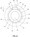
- the annular shoulder surface 116 comprises a high point 117 and a low point 118 when viewed in side profile as shown in FIG. 5 .
- the low point 118 is located closer to the proximal end 111 of the gripping portion 110 than the high point 117. Furthermore, the high point 117 is circumferentially aligned with the stem rotational alignment element 140. Thus, the high point 117 and the stem rotational alignment element 140 are located at the same rotational position about the stem axis A-A, although the high point 117 and the stem rotational alignment element 140 may be at different radial distances from the axis and/or at different axial positions in other embodiments.
- the stem guide section 123 is the axial section of the stem body 121 that is between the stem base section 122 and the stem interference section 124.
- the stem guide section 123 has a conical shape in that its width decreases as it extends further from the stem base section 122 and closer to the stem interference section 124. More specifically, the stem guide section 123 has a transverse cross-sectional area that tapers with increasing distance from the distal end 112 of the gripping portion 110 of the handle 100.
- the stem guide section 123 has a fairly significant taper that is noticeable simply by viewing the stem.
- the stem interference section 124 also tapers. Specifically, the stem interference section 124 has a transverse cross-sectional area that tapers with increasing distance from the distal end 112 of the gripping section 110 of the handle 100. However, as seen in the drawings, the taper of the stem interference section 124 is quite minor such that it is almost imperceptible in the drawings. That said, in this embodiment the stem interference section 124 does taper as described. Stated another way, the stem interference section 124 has a first transverse width W1 adjacent to the stem guide section 123 and a second transverse width W2 at the distal end 113 of the handle 100, the first transverse width W1 being greater than the second transverse width W2. In the exemplified embodiment, the transverse cross-sectional area of the stem guide section 123 has a greater degree of taper than the transverse cross-sectional area of the stem interference section 124.
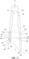
- the oral care refill head 200 comprises the oral care treatment portion 210 and the sleeve portion 220.
- the oral care treatment portion 210 comprises the head body 211 having a front surface 212 from which the tooth cleaning elements 214 extend and an opposite rear surface 213.
- the oral care refill head 200 extends from the proximal end 201 that is formed by the proximal edge surface 222 of the sleeve portion 220 to a distal end 202 that is formed by the terminal end of the oral care treatment portion 210.
- the proximal edge surface 222 of the sleeve portion 220 defines an opening 230 into the sleeve cavity 221.
- the sleeve cavity 221 is open at the proximal edge surface 222 of the sleeve portion 220.
- the sleeve cavity 221 extends along a cavity axis B-B.
- the proximal edge surface 222 of the sleeve portion 220 lies in a second reference plane RP2 that is oblique to the cavity axis B-B. This allows the proximal edge surface 222 of the sleeve portion 220 to abut the annular shoulder surface 116 of the handle 100 when the oral care refill head 200 is coupled to the handle 100.
- a front portion 203 of the proximal edge surface 222 of the sleeve portion 220 is located a first axial distance D1 from a distal end 249 of the sleeve portion 220.
- a rear portion 204 of the proximal edge surface 222 of the sleeve portion 220 is located a second axial distance D2 from the distal edge 249 of the sleeve portion 220.
- the second axial distance D2 is greater than the first axial distance D1.
- proximal edge surface 222 of the sleeve portion 220 is angled upwardly in a direction from a rear surface 205 of the sleeve portion 220 (which faces generally the same direction as the rear surface 213 of the head body 211) to a front surface 206 of the sleeve portion 220 (which faces generally the same direction as the front surface 212 of the head body 211).
- the front portion 203 of the proximal edge surface 222 of the sleeve portion 220 is a high point of the proximal edge surface 222 and the rear portion 204 of the proximal edge surface 222 of the sleeve portion 220 is a low point of the proximal edge surface 222, when viewed in side profile.
- the front portion 203 of the proximal edge surface 222 of the sleeve portion 220 comprises an inner apex 248 having an acute angle ⁇ .
- the head body 211 of the oral care refill head 200 extends along a head longitudinal axis C-C that is inclined relative to the cavity axis B-B.
- the head longitudinal axis C-C is inclined forward moving from a proximal end of the head body 211 that is adjacent to the sleeve portion 220 to a distal end of the head body 211 (which is also the distal end 202 of the oral care refill head 200).
- the sleeve portion 220 of the oral care refill head 100 comprises a sleeve interference section 223, a sleeve guide section 224, a sleeve snap element 225, and a sleeve rotational alignment element 226.
- the sleeve guide section 224 is located between the sleeve interference section 223 and the sleeve snap element 225.
- the sleeve guide section 224 is also located between the sleeve interference section 223 and the sleeve rotational alignment element 226.
- the sleeve guide section 224 is located between the sleeve interference section 223 and the proximal edge surface 222 of the sleeve portion 220.
- the sleeve interference section 223 forms a distal-most section of the sleeve cavity 221 and comprises an end wall 219 of the sleeve cavity 221.
- the sleeve cavity 221 has a transverse cross-sectional area that tapers with distance from the proximal end 201 of the sleeve portion 220 in the sleeve guide section 224.
- the sleeve guide section 224 comprises a portion of the sleeve cavity 221 that tapers as the distance from the proximal end 201 of the sleeve portion 220 increases. This enables the portion of the sleeve cavity 221 associated or aligned with the sleeve guide section 224 to receive the stem guide section 123 of the stem 120 of the handle 100 when the oral care refill head 200 is coupled to the handle 100.
- the transverse cross-sectional area of the sleeve cavity 221 also tapers with increasing distance from the proximal end 201 of the sleeve portion 220 in the sleeve interference section 223.
- the sleeve cavity 221 tapers along both the sleeve guide section 224 and the sleeve interference section 223.
- the transverse cross-sectional area of the sleeve cavity 221 in the sleeve guide section 224 has a greater degree of taper than the transverse cross-sectional area of the sleeve cavity 221 in the sleeve interference section 223.
- the sleeve cavity 221 is defined by an inner surface 227 of the sleeve portion 220.
- the sleeve snap element 225 comprises a sleeve ring 228 that protrudes from the inner surface 227 of the sleeve portion 220.
- the sleeve ring 228 extends circumferentially around the inner surface 227 of the sleeve portion 220.
- the sleeve ring 228 does not extend along the entirety of the circumference of the inner surface 227 of the sleeve portion 220. Rather, the sleeve ring 228 is interrupted by the sleeve rotational alignment element 226, as described further below.
- the sleeve ring 228 of the sleeve snap element 225 is a continuous protrusion that extends from the inner surface 227 of the sleeve portion 220 along an entire circumference thereof with the exception of the location of the sleeve rotational alignment element 226.
- the invention is not to be so limited in all embodiments and the sleeve ring 228 of the sleeve snap element 225 could comprise a plurality of ring segments that are spaced apart from one another.
- the sleeve snap element 225 could comprise a groove instead of a protuberance while still forming a snap-interlock with the stem snap element 130 described above.
- the sleeve snap element 225 is spaced a distance from the proximal end 222 of the sleeve portion 220 towards the oral treatment portion 210.
- the sleeve snap element 225 is circumscribed by a wall of the sleeve portion 220.
- the sleeve snap element 225 is surrounded on all sides by a portion of the wall of the sleeve portion 220. The sleeve snap element 225 does not extend to the proximal end 222 of the sleeve portion 220 in the exemplified embodiment.
- the sleeve rotational alignment element 226 comprises a sleeve groove 229 formed into the inner surface 227 of the sleeve portion 220 that defines the sleeve cavity 221.
- the sleeve groove 229 extends axially from an open groove end 231 in the proximal edge 201 of the sleeve portion 220 to a closed groove end wall 232.
- the open groove end 231 of the sleeve groove 229 of the sleeve rotational alignment element 226 forms a part of the opening 230 into the sleeve cavity 221 at the proximal edge surface 222 of the sleeve portion 220.
- the sleeve groove 229 of the sleeve rotational alignment element 226 extends upward from the front portion 203 of the proximal edge surface 222 of the sleeve portion 220.
- the sleeve groove 229 has a first side wall 233 and a second side wall 234.
- the sleeve rotational alignment element 226 is circumferentially aligned with the front surface 212 of the head body 211 of the oral treatment portion 210 of the oral care refill head 200.
- the sleeve rotational alignment element 226 could be located at other circumferential positions in other embodiments.
- the sleeve snap element 225 and the sleeve rotational alignment element 226 are positioned on the sleeve so that a fourth reference plane RP4 that is transverse to the cavity axis A-A intersects both the sleeve snap element 225 and the sleeve rotational alignment element 226.
- the sleeve snap element 225 and the sleeve rotational element 226 are at least partially axially aligned with one another and the sleeve snap element 225 intersects the sleeve rotational alignment element 226.
- the sleeve snap element 225 extends from a first end 235 that terminates at the first side wall 233 of the sleeve rotational alignment element 226 to a second end 236 that terminates at the second side wall 234 of the sleeve rotational alignment element 226.
- the sleeve groove 229 of the sleeve rotational alignment element 226 creates a space or gap in the sleeve ring 228 of the sleeve snap element 225 in the exemplified embodiment.
- the sleeve portion 220 of the oral care refill head 200 has an outer surface 207 that includes the front and rear surfaces 205, 206.
- the outer surface 207 extends from the distal end 249 of the sleeve portion 220 to the proximal edge surface 222 of the sleeve portion 220.
- there are no relief slots or the like that extend from the outer surface 207 to the inner surface 227 to form passageways into the cavity 221 from the outer surface 225.
- the entire connection between the oral care refill head 200 and the handle 100 is accomplished by features, elements, and components that are located within or form a part of the sleeve cavity 221.
- FIGS. 12A-14B illustrate the process of coupling the oral care refill head 200 to the handle 100 in partial perspective views along with a matching cross-sectional view.
- the first step is to align the opening 230 of the sleeve cavity 221 with the stem 120 of the handle 100, and particularly with the distal end 113 of the handle 100.
- the oral care refill head 200 is lowered so that the stem 120 of the handle 100 enters the sleeve cavity 221 of the sleeve portion 220 of the oral care refill head 200.
- the stem rotational alignment element 140 must be rotationally/circumferentially aligned with the sleeve rotational alignment element 226 in order for the stem 120 to be inserted into the sleeve cavity 221 as deeply as shown in FIGS. 13A and 13B .
- the stem interference section 124 and the stem guide section 123 of the stem 120 can pass through the opening 230 in the proximal end 222 of the sleeve portion 220 without regard to the relative rotational orientations of the oral care refill head 200 and the handle 100.
- the stem rib 141 of the stem rotational alignment element 140 will bump against the proximal edge surface 222 of the sleeve portion 220 of the oral care refill head 200 and prevent further insertion of the stem 120 into the sleeve cavity 221.
- the stem 120 will be able to be further inserted into the sleeve cavity 221 such that the stem rotational alignment element 140 mates with and nests within the sleeve rotational alignment element 226 as shown in FIG. 13B .
- the stem 120 of the handle 100 is partially nested within the sleeve cavity 221 of the oral care refill head 200 to the point that the stem snap element 130 is abutting against the sleeve snap element 225.
- both the stem snap element 130 and the sleeve snap element 225 are protuberances.
- an additional force is required by the user to force the stem snap element 130 to move axially past the sleeve snap element 225.
- at least one of the stem snap element 130 and the sleeve snap element 225 may be a groove instead of a protuberance.
- the oral care refill head 200 is illustrated in the second state in which it is fully coupled to the handle 100.
- the stem snap element 130 has passed over the sleeve snap element 225, thereby creating a snap-fit interlock between the stem snap element 130 and the sleeve snap element 225.
- This may be achieved by the sleeve portion 220 of the oral care refill head 200 flexing slightly outward as the stem snap element 130 passes over the sleeve snap element 225.
- the oral care refill head 200 is securely coupled to the handle 100 such that a force that overcomes the snap-fit interlock is required to be applied to the oral care refill head 200 and/or the handle 100 in opposite directions in order to detach the oral care refill head 200 from the handle 100.
- the stem rib 141 of the stem rotational alignment element 140 nests within the sleeve groove 229 of the sleeve rotational alignment element. This not only ensures that the oral care refill head 200 is initially coupled to the handle 100 in the correct rotational orientation, but also prevents the oral care refill head 200 from being rotated relative to the handle 100 once the oral care refill head 200 is coupled to the handle 100.
- the oral care refill head 200 cannot be altered from the first state (whereby it is separated from the handle 100) to the second state (whereby it is coupled to the handle 100) unless the stem alignment element 140 and the sleeve alignment element 226 are circumferentially aligned (i.e., at the same rotational position about the stem and cavity axes A-A, B-B) with one another.
- the oral care refill head 200 when the oral care refill head 200 is coupled to the handle 100, there is an interference fit between the stem interference section 124 and the sleeve interference section 123. In some embodiments, this means that there is a pressure, even if ever so slightly, applied by the inner surface 227 of the sleeve portion 220 of the oral care refill head 200 against an outer surface 129 of the stem interference section 124 of the stem 120.
- the external dimension of the stem interference section 124 (i.e., the width measured in a direction transverse to the stem axis A-A) may be slightly greater than the internal dimension of the sleeve interference section 223 (i.e., the width of the sleeve cavity 221 along the sleeve interference section 223 measured in a direction transverse to the cavity axis B-B).
- the stem interference section 124 nests within the sleeve cavity 221 along the sleeve interference section 223, the stem interference section 124 fits snugly therein.
- This interference fit between the stem interference section 124 and the sleeve interference section 223 may prevent relative movement (rocking, rattling, shaking, or the like) between the oral care refill head 200 and the handle 100 during use of the oral care implement 1000.
- the interference fit formed between the stem interference section 124 and the sleeve interference section 223 may extend a length that is 25% or more of a total length of the stem 120.
- the stem 120 comprises the annular groove 126.
- annular groove 126 is formed into the stem 120, in other embodiments an annular groove that is aligned with the annular space 160 may be formed into the inner surface 227 of the sleeve portion 220 rather than it being formed into the stem 120.
- the annular groove 126 may be formed in one of the sleeve portion 220 or the stem 120 to form the annular space 160 when the stem 120 nests within the sleeve cavity 220.
- the annular space 160 is located at an axial position between the interference fit and the snap-fit interlock.
- the annular space 160 is adjacent to the interference fit and located along the junction of the sleeve interference section 124 and the sleeve guide section 123.
- the stem guide section 123 of the stem 120 nests within the sleeve guide section 224 of the sleeve portion 220.
- the sleeve guide section 224 is configured to axially orient the stem 120 within the sleeve cavity 221 through the interaction between the stem guide section 123 of the stem 120 and the sleeve guide section 224 of the sleeve portion 220 during insertion of the stem 120 into the sleeve cavity 221.
- a gap 161 may exist between the stem guide section 123 and the sleeve guide section 224.
- the proximal edge surface 222 of the sleeve portion 220 of the oral care refill head 200 is adj acent to or abuts the shoulder 116 at the distal end 112 of the gripping portion 110 of the handle 100. More specifically, the proximal edge surface 222 of the sleeve portion 220 of the oral care refill head 200 is in abutment with the annular shoulder surface 116 of the gripping portion 110 of the handle 100.
- the snap-fit interlock between the stem snap element 130 and the sleeve snap element 225 biases or forces the proximal edge surface 222 of the sleeve portion 220 against (into abutment with) the annular shoulder surface 116 of the gripping portion 110 of the handle 100.
- the annular shoulder surface 116 lies on a third reference plane RP3 and the proximal edge surface 222 lies on a second reference plane RP2.
- the second and third reference planes RP2, RP3 are parallel to one another.
- the multiple features include: (1) the interference fit between the sleeve interference section 223 and the stem interference section 124; (2) the snap-fit interlock between the sleeve snap element 225 and the stem snap element 130; (3) the mating between the sleeve rotational alignment element 226 and the stem rotational alignment element 140 to prevent relative rotation between the handle 100 and the oral care refill head 200; and (4) the abutment between the proximal edge surface 222 of the sleeve portion 220 of the oral care refill head 200 and the annular shoulder surface 116 at the distal end 112 of the handle portion 110 of the handle 100.
- Various embodiments may include any of one or more of these four features in accordance with the teachings set forth herein to achieve an acceptable coupling between the oral care refill head 200 and the handle 100.
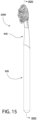
- an oral care implement 2000 is illustrated in accordance with another embodiment of the present invention.
- the oral care implement 2000 is identical to the oral care implement 1000 described above, except with regard to the differences described below. Therefore, to the extent that features of the oral care implement 2000 are not described in detail herein, it should be appreciated that the features of the oral care implement 1000 are applicable.
- Features of the oral care implement 2000 that are the same as features of the oral care implement 1000 are similarly numbered, except the 300 and 400 series of numbers are used for the oral care implement 2000 instead of the 100 and 200 series of numbers which were used for the oral care implement 1000.
- the disclosure of the present invention should be deemed to include combinations of the features of the oral care implements 1000, 2000 described herein so long as they do not conflict.
- the oral care implement generally comprises a handle 300 and an oral care refill head 400.
- the details of the oral care implement 2000 that differ from the oral care implement 1000 relate to features based around the connection and coupling between the handle 300 and the oral care refill head 400.
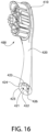
- the handle 300 comprises a gripping portion 310 and a stem 320.
- the gripping portion 310 extends from a proximal end 311 to a distal end 312.
- the stem 320 extends along a stem axis D-D and protrudes from the distal end 312 of the gripping portion 310.
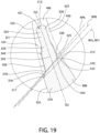
- the distal end 312 of the gripping portion 310 comprises an annular shoulder surface 316 that circumscribes the stem 320.
- the stem 320 comprises a stem body 321, which protrudes from the distal end 312 of the gripping portion 310 of the handle 300 and terminates at a distal end 313 of the handle 300.
- the stem 320 (and the stem body 321 thereof) extends along the stem axis A-A from the distal end 312 of the gripping portion 310 of the handle 300 to the distal end 313 of the handle 300.
- the stem body 21 comprises a stem base section 322, a stem guide section 323, and a stem interference section 324.
- the stem base section 322, the stem guide section 323, and the stem interference section 324 all form a part of the monolithic stem body 121 in the exemplified embodiment.
- the stem 320 comprises a stem snap element 330 and a stem rotational alignment element 340.
- the stem snap element 330 and the stem rotational alignment element 340 are located on the stem base section 322 of the stem 320. More specifically, in the exemplified embodiment the stem snap element 330 and the stem rotational element 340 are located entirely on the stem base section 322 such that no portion of the stem snap element 330 or the stem rotational element 340 extends onto the stem guide section 323 of the stem 320.
- the stem snap element 330 and/or the stem rotational alignment element 340 may be located partially or fully on the stem guide section 323 or the stem interference section 324.
- the details of the stem snap element 130 and the stem rotational alignment element 140 described above are applicable to the stem snap element 330 and the stem rotational alignment element 340.
- the annular shoulder surface 316 of the distal end 312 of the gripping portion 310 of the handle 300 extends radially from an outer shoulder edge 317 to an inner shoulder edge 318, with the inner shoulder edge 318 being adjacent to the stem 320 and the outer shoulder edge 317 being adjacent to an outer surface 325 of the handle 300.
- the annular shoulder surface 316 is inclined downwardly and away from the stem 320. That is, an entirety of the annular shoulder surface 316 is inclined downwardly and away from the stem 320.
- downwardly as used herein means away from the distal end 313 of the handle 310 and towards the proximal end 311 of the handle 310.
- the annular shoulder surface 316 is inclined downwardly away from the stem 320 and away from the distal end 313 of the handle 310 with increasing distance from the stem axis D-D in the exemplified embodiment. It may be possible to incline the annular shoulder surface 316 in the opposite direction in some alternative embodiments. Thus, the annular shoulder surface 316 could be inclined upwardly towards the distal end of the stem 320 with increasing distance from the stem axis D-D in other embodiments.
- the inner shoulder edge 318 which is an annular edge that surrounds the stem 320, is located further from the proximal end 311 of the handle 310 than the outer shoulder edge 317, which is also an annular edge that surrounds the stem 320.
- the annular shoulder surface 316 may be a conical surface in some embodiments.
- the annular shoulder surface 316 still has a high point and a low point as was discussed above with regard to the oral care implement 1000. However, in this embodiment the annular shoulder surface 316 does not, in its entirety, lie in a single plane. Rather, in this embodiment the outer shoulder edge 317 lies in a fifth reference plane RP5 that is oblique to the stem axis D-D. Furthermore, the inner shoulder edge 318 lies in a sixth reference plane RP6 that is oblique to the stem axis D-D.
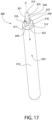
- the oral care refill head 400 comprises an oral care treatment portion 410 and a sleeve portion 420.
- the sleeve portion 420 comprises a sleeve cavity 421 extending along a cavity axis E-E.
- the sleeve portion 420 of the oral care refill head 400 comprises a sleeve interference section 423, a sleeve guide section 424, a sleeve snap element 425, and a sleeve rotational alignment element 426.
- the sleeve portion 420 comprises a proximal edge surface 422 that defines an opening into the sleeve cavity 421.
- the proximal edge surface 422 of the sleeve portion 420 extends radially from an outer sleeve edge 423 to an inner sleeve edge 424, with the inner sleeve edge 424 being closer to the cavity axis E-E than the outer sleeve edge 423.
- the proximal edge surface 422 is inclined downwardly away from the oral treatment portion 410 with increasing radial distance from the cavity axis E-E.
- an entirety of the proximal edge surface 422 is inclined downwardly and away from the cavity axis E-E with increasing radial distance from the cavity axis E-E.
- the term downwardly means that the proximal edge surface 422 is inclined in a direction away from the oral treatment portion 410 of the oral care refill head 400.
- the proximal edge surface 422 also extends further from the oral treatment portion 410 of the oral care refill head 400.
- the proximal edge surface 422 forms a sort of funnel shape.
- Each of the inner sleeve edge 424 and the outer sleeve edge 423 forms an annular edge that surrounds the cavity axis E-E.
- the inner sleeve edge 424 is closer to the cavity axis E-E and closer to the oral care treatment portion 410 than the outer sleeve edge 423.
- the proximal edge surface 422 may be inclined upwardly towards the oral care treatment portion 410.
- the proximal edge surface 422 has a high point and a low point as discussed above with regard to the oral care implement 1000 that enables the proximal edge surface 422 to mate with the annular shoulder surface 316 when the oral care refill head 400 is coupled to the handle 300.
- the outer sleeve edge 423 of the proximal edge surface 422 lies in a seventh reference plane RP7 that is oblique to the cavity axis E-E (which, when the oral care refill head 400 is attached to the handle 300, is the same plane as the fifth reference plane RP5 in which the outer shoulder edge 317 of the annular shoulder surface 316 lies).
- the inner sleeve edge 424 of the proximal edge surface 422 lies in an eighth reference plane RP8 that is oblique to the cavity axis E-E.
- the seventh reference plane RP7 does not intersect any portion of the oral care refill head 400 other than the outer sleeve edge 423 of the proximal edge surface 422.
- no portion of the proximal edge surface 422 other than the outer sleeve edge 423 lies on the seventh reference plane RP7.
- the inner sleeve edge 424 does not lie in and is not intersected by the seventh reference plane RP7 in which the outer sleeve edge 423 lies, and the outer sleeve edge 423 does not lie in and is not intersected by the eighth reference plane RP8 in which the inner sleeve edge 424 lies.
- the entirety of the proximal edge surface 422 with the exception of the inner sleeve edge 424 is located on one side of the eighth reference plane RP8 and the rest of the oral care refill head 400 is located on the other side of the eighth reference plane RP8.
- a front portion 456 of the outer sleeve edge 423 of the proximal edge surface 422 of the sleeve portion 420 is located at a first axial distance D1 from a distal end 459 of the sleeve portion 420. Furthermore, a rear portion 457 of the outer sleeve edge 423 of the proximal edge surface 422 of the sleeve portion 420 is located at a second axial distance D2 from the distal end 459 of the sleeve portion 420. In the exemplified embodiment, the second axial distance D2 is greater than the first distance D1 (best seen in FIG. 18 ).
- the front portion 456 of the outer sleeve edge 423 of the proximal edge surface 422 of the sleeve portion 420 is the high point of the proximal edge surface 422 and the rear portion 457 of the outer sleeve edge 423 of the proximal edge surface 422 of the sleeve portion 420 is the low point of the proximal edge surface 422, when viewed in side profile (and see in the sectional view of FIG. 18 ).
- the stem 320 of the handle 300 is disposed within the sleeve cavity 421 of the sleeve portion 420 of the oral care refill head 400 so that the proximal edge surface 422 of the oral care refill head 400 is adjacent to (or in abutting contact with) the annular shoulder surface 316 of the handle 300.
- the interference fit and the snap-fit interlock described in detail above and not repeated herein in the interest of brevity may accomplish the securing of the oral care refill head 400 to the handle 300.
- the fifth and seventh reference planes RP5, RP7 are parallel to one another and oblique to each of the sixth and eight reference planes RP6, RP8, and the sixth and eighth reference plane RP6, RP8 are also oblique to one another.
- reference plane is not necessarily consistent in the specification and the claims. Rather, the numerical values used in the specification are merely used to distinguish one reference plane from another. The same is done in the claims, although the prefixes for the reference planes in the claims are simply listed sequentially as they appear in the claims rather than listed in a way that corresponds with the way that same reference plane is described in the specification.
Landscapes
- Health & Medical Sciences (AREA)
- Dentistry (AREA)
- Epidemiology (AREA)
- Life Sciences & Earth Sciences (AREA)
- Animal Behavior & Ethology (AREA)
- General Health & Medical Sciences (AREA)
- Public Health (AREA)
- Veterinary Medicine (AREA)
- Brushes (AREA)
Abstract
Description
- Toothbrushes having replaceable heads have been used for many years, enabling users to replace the head of the toothbrush for continued use with the same handle. This is often used for electric toothbrushes because the expensive electronic circuitry is stored in the handle making it cost-prohibitive to have to dispose of the handle each time that the cleaning elements on the head have worn out and require replacement. However, there are also manual toothbrushes in existence that utilize a replaceable head, which can be beneficial to the environment, for example, because less plastic waste is being added to the landfills when only the head is being replaced every three months or so. There is a continuing need for an improvement in the connection mechanism between the handle and the replaceable heads configured to be attached thereto.
- The present invention is directed to an oral care implement that includes a handle and an oral care refill head. The oral care refill head is alterable between a first state in which it is separated from the handle and a second state in which it is coupled to the handle. The oral care refill head has a proximal edge surface that defines an opening into a sleeve cavity. The proximal edge surface is inclined downwardly and away with radial distance from a cavity axis of the sleeve cavity. Similarly, the handle has a gripping portion that terminates at a distal end and a stem that protrudes from the distal end. The annular shoulder that is inclined downwardly and away from a stem to facilitate mating of the oral care refill head to the handle. The oral care refill head may have features for securing the oral care refill head to the stem of the handle.
- In one aspect, the invention may be an oral care implement comprising: a handle comprising: a gripping portion having a distal end; and a stem extending along a stem axis and protruding from the distal end of the gripping portion so that the distal end of the gripping portion comprises an annular shoulder surface that circumscribes the stem, the stem comprising a stem interference section and a stem snap element; the annular shoulder surface extending radially from an outer shoulder edge to an inner shoulder edge adjacent the stem, the annular shoulder surface inclined from the inner shoulder edge to the outer shoulder edge in one direction either upwardly towards the distal end of the stem or downwardly away from the distal end of the stem with increasing distance from the stem axis; and a sleeve portion comprising a sleeve cavity extending along a cavity axis, a proximal edge surface defining an opening into the sleeve cavity, a sleeve interference section, and a sleeve snap element; and the proximal edge surface of the sleeve portion extending radially from an outer sleeve edge to an inner sleeve edge, the proximal edge surface inclined from the inner sleeve edge to the outer sleeve edge in one direction either upwardly towards the oral treatment portion or downwardly away from oral treatment portion with increasing distance from the cavity axis; the oral care refill head alterable between: a first state in which the oral care refill head is separated from the handle; and a second state in which the stem of the handle is disposed within the sleeve cavity of the sleeve portion so that the proximal edge surface of the oral care refill head is adjacent the annular shoulder surface of the handle, the oral care refill head secured to the handle by at least: (1) an interference fit between the stem interference section and the sleeve interference section; and (2) a snap-fit interlock between the stem snap element and the sleeve snap element.
- In another aspect, the invention may be an oral care refill head for detachable coupling to a stem of a handle, the oral care refill head comprising: an oral care treatment portion; and a sleeve portion comprising: a sleeve cavity extending along a cavity axis; a sleeve interference section configured to form an interference fit with a stem interference section of the stem; a sleeve snap element configured to snap-interlock with a stem snap element of the stem; and a proximal edge surface that defines an opening into the sleeve cavity, the proximal edge surface of the sleeve portion extending radially from an outer sleeve edge to an inner sleeve edge, the proximal edge surface inclined from the inner sleeve edge to the outer sleeve edge in one direction either upwardly towards the oral treatment portion or downwardly away from oral treatment portion with increasing distance from the cavity axis.
- In yet another aspect, the invention may be an oral care refill head for detachable coupling to a stem of a handle, the oral care refill head comprising: an oral care treatment portion comprising a front surface facing a first direction, a plurality of tooth cleaning elements protruding from the front surface; and a sleeve portion comprising: a distal end to which the oral care treatment portion is coupled; a front surface facing the first direction and a rear surface facing a second direction, the second direction opposite the first direction; a sleeve cavity extending along a cavity axis and configured to receive the stem of the handle; a proximal edge surface that defines an opening into the sleeve cavity, the proximal edge surface extending from an outer sleeve edge to an inner sleeve edge, wherein a front portion of the outer sleeve edge is located a first axial distance from the distal end of the sleeve portion and a rear portion of the outer sleeve edge of the sleeve portion is located a second axial distance from the distal end of the sleeve portion, the second axial distance greater than the first axial distance; a sleeve snap element configured to snap-interlock with a stem snap element of the stem, the sleeve snap element circumscribed by a wall of the sleeve portion.
- In a further aspect, the invention may be a handle for detachably coupling to an oral care refill head, the handle comprising: a gripping portion having a distal end; and a stem extending along a stem axis and protruding from the distal end of the gripping portion, the stem comprising: a stem body having an outer surface; a stem ring protruding from and extending circumferentially around the outer surface of the stem body, the stem ring configured to snap-interlock with a sleeve snap element of a sleeve portion of the oral care refill head; a stem rib that protrudes from and extends axially along an outer surface of a stem body, the stem rib intersecting the stem ring; and the stem rib protruding a first height from the outer surface of the stem body and the stem ring protruding a second height from the outer surface of the stem body, the second height being less than the first height.
- In a still further aspect, the invention may be an oral care refill head for detachable coupling to a stem of a handle, the oral care refill head comprising: an oral care treatment portion; and a sleeve portion comprising: a sleeve cavity extending along a cavity axis and configured to receive the stem of the handle; a proximal edge surface that defines an opening into the sleeve cavity, the proximal edge surface of the sleeve portion extending radially from an outer sleeve edge to an inner sleeve edge, the proximal edge surface inclined from the inner sleeve edge to the outer sleeve edge in one direction either upwardly towards the oral treatment portion or downwardly away from oral treatment portion with increasing distance from the cavity axis; and one or more features for securing the oral care refill head to the stem of the handle.
- Further areas of applicability of the present invention will become apparent from the detailed description provided hereinafter. It should be understood that the detailed description and specific examples, while indicating the preferred embodiment of the invention, are intended for purposes of illustration only and are not intended to limit the scope of the invention.
- The present invention will become more fully understood from the detailed description and the accompanying drawings, wherein:
-
FIG. 1 is a perspective view of an oral care implement in accordance with an embodiment of the present invention, whereby a handle and an oral care refill head are in an attached state; -
FIG. 2 is a perspective view of the oral care implement ofFIG. 1 with the handle and the oral care refill head thereof in a detached state; -
FIG. 3 is a close-up perspective view of area III ofFIG. 2 ; -
FIG. 4 is a close-up front view of area III ofFIG. 2 ; -
FIG. 5 is a close-up side view of area III ofFIG. 2 ; -
FIG. 6 is a top view of the handle of the oral care implement ofFIG. 1 ; -
FIG. 7 is a cross-sectional view taken along line VII-VII ofFIG. 4 ; -
FIG. 8 is a front view of the oral care refill head ofFIG. 1 ; -
FIG. 9 is a side view of the oral care refill head ofFIG. 1 ; -
FIG. 10 is a bottom view of the oral care refill head ofFIG. 1 ; -
FIG. 11 is a cross-sectional view taken along line XI-XI ofFIG. 8 ; -
FIG. 12A is a perspective view illustrating the oral care refill head ofFIG. 1 positioned in alignment with a stem portion of the handle ofFIG. 1 for attachment thereto; -
FIG. 12B is a cross-sectional view taken along line XII-XII ofFIG. 12A ; -
FIG. 13A is a perspective view illustrating the stem portion of the handle ofFIG. 1 partially inserted into a cavity of the oral care refill head ofFIG. 1 ; -
FIG. 13B is a cross-sectional view taken along line XIII-XIII ofFIG. 13A ; -
FIG. 14A is a perspective view illustrating the oral care refill head ofFIG. 1 and a portion of the handle ofFIG. 1 in the attached state; -
FIG. 14B is a cross-sectional view taken along line XIV-XIV ofFIG. 14A ; -
FIG. 15 is a perspective view of an oral care implement having a handle and an oral care refill head in accordance with an alternative embodiment of the present invention; -
FIG. 16 is a perspective view of the handle ofFIG. 15 ; -
FIG. 17 is a perspective view of the oral care refill head ofFIG. 15 ; -
FIG. 18 is a cross-sectional view taken along line XVIII-XVIII ofFIG. 15 ; and -
FIG. 19 is a close-up view of area XIX ofFIG. 16 . - The following description of the preferred embodiment(s) is merely exemplary in nature and is in no way intended to limit the invention, its application, or uses.
- The description of illustrative embodiments according to principles of the present invention is intended to be read in connection with the accompanying drawings, which are to be considered part of the entire written description. In the description of embodiments of the invention disclosed herein, any reference to direction or orientation is merely intended for convenience of description and is not intended in any way to limit the scope of the present invention. Relative terms such as "lower," "upper," "horizontal," "vertical," "above," "below," "up," "down," "top" and "bottom" as well as derivatives thereof (e.g., "horizontally," "downwardly," "upwardly," etc.) should be construed to refer to the orientation as then described or as shown in the drawing under discussion. These relative terms are for convenience of description only and do not require that the apparatus be constructed or operated in a particular orientation unless explicitly indicated as such. Terms such as "attached," "affixed," "connected," "coupled," "interconnected," and similar refer to a relationship wherein structures are secured or attached to one another either directly or indirectly through intervening structures, as well as both movable or rigid attachments or relationships, unless expressly described otherwise. Moreover, the features and benefits of the invention are illustrated by reference to the exemplified embodiments. Accordingly, the invention expressly should not be limited to such exemplary embodiments illustrating some possible non-limiting combination of features that may exist alone or in other combinations of features; the scope of the invention being defined by the claims appended hereto.
- Referring first to
FIGS. 1 and2 , anoral care implement 1000 is illustrated in accordance with an embodiment of the present invention. In the exemplified embodiment, the oral care implement 1000 is a manual toothbrush. However, the invention is not to be so limited in all embodiments and theoral care implement 1000 can take on other structural forms, including being a powered toothbrush, a tongue scraper, a gum and soft tissue cleanser, a water pick, an interdental device, a tooth polisher, a specially designed ansate implement having tooth engaging elements, or any other type of implement that is commonly used for oral care. Furthermore, in still other embodiments the implement may not be specifically used for oral care, but could instead be a personal care implement which includes the various types of oral care implements noted herein and also includes hairbrushes, razors, body scrubbers, skin treatment devices, or the like. Thus, it is to be understood that the inventive concepts discussed herein can be applied to any type of oral care implement or personal care implement unless a specific type of implement is specified in the claims. - The oral care implement 1000 generally comprises a
handle 100 and an oralcare refill head 200. Thehandle 100 is the portion of the oral care implement 1000 that is gripped by a user during use of the oral care implement 1000 and the oralcare refill head 200 is the portion of the oral care implement 1000 that includes a treatment portion for performing a treatment to the user, such as a cleaning of the oral cavity. The oralcare refill head 200 is alterable between a first state in which the oralcare refill head 200 is separated from the handle (as shown inFIG. 2 ) and a second state in which the oralcare refill head 200 is coupled to the handle 100 (as shown inFIG. 1 ). Thus, the oralcare refill head 200 is replaceable so that once the treatment portion thereof becomes worn, it can be replaced with a new oral care refill head by attaching the new oral care refill head to the samecommon handle 100. This may reduce costs and waste which consumers find desirable in today's climate. - The
handle 100 generally comprises agripping portion 110 extending from aproximal end 111 to adistal end 112 and astem 120 extending or protruding from thedistal end 112 of thegripping portion 110. The grippingportion 110 of thehandle 100 is the portion that is typically gripped and manipulated by a user during user of the oral care implement 1000 to perform a treatment function. In the exemplified embodiment, the grippingportion 110 of thehandle 100 has a round or circular/oval cross-sectional shape. However, the invention is not to be limited by this in all embodiments and thegripping portion 110 can take on any desired shape including having additional recesses, contours, or the like to enhance gripability. Thestem 120 of thehandle 100 is the portion that is used to couple thehandle 100 to the oralcare refill head 200, as will be described in much greater detail below. Thus, thestem 120 has features that facilitate the attachment of thehandle 100 to the oralcare refill head 200. Thestem 120 comprises astem body 121 having several different sections that serve different functions in achieving an acceptable coupling between thehandle 110 and the oralcare refill head 200. - The
stem 120 and thegripping portion 110 are integrally formed as a unitary and monolithic component in the exemplified embodiment. Thus, in the exemplified embodiment the entirety of thehandle 100 is formed out of a first material. In some embodiments, the first material may have a first hardness. In some embodiments, the first material may be a metal or a metal alloy. In other embodiments the first material may be wood or a hard plastic. In other embodiments, the grippingportion 110 and thestem 120 may be formed from different materials. Thus, for example, the grippingportion 110 may be formed from metal or a metal alloy and thestem 120 may be formed from a hard plastic. In other embodiments, the grippingportion 110 may be formed from a hard plastic and thestem 120 may be formed from metal or a metal alloy. In still other embodiments, the grippingportion 110 may be formed from wood and thestem 120 may be formed from metal, metal alloys, hard plastic, or combinations thereof. Thus, some variation in the material used to form the different parts of thehandle 100 may be possible in some embodiments. - The oral
care refill head 200 comprises an oral care treatment portion and asleeve portion 220. Thesleeve portion 220 comprises asleeve cavity 221 that is configured to receive at least a portion of thestem 120 of thehandle 100 for purposes of coupling the oralcare refill head 200 to thehandle 100. The oralcare refill head 200 extends from aproximal end 201 that is formed by aproximal edge surface 222 of thesleeve portion 220 to adistal end 202 that is formed by a terminal end of the oralcare treatment portion 210. The oralcare treatment portion 210 comprises ahead body 211 located at a distal end of thesleeve portion 220. Thehead body 211 may be integrally formed with thesleeve portion 220 as a monolithic component. Thehead body 211 has afront surface 212 facing a first direction and arear surface 213 facing a second direction that is opposite the first direction. The oralcare treatment portion 210 also comprises a plurality oftooth cleaning elements 214 protruding from thefront surface 212 of thehead body 211 in the first direction. - In the exemplified embodiment, the plurality of
tooth cleaning elements 214 comprises a plurality ofbristle tufts 215 and a plurality ofelastomeric cleaning elements 216. Thebristle tufts 215 and the elastomeric cleaning elements 107 collectively form a cleaning element field on thehead body 211. The particular arrangement and/or pattern and/or location of thevarious bristle tufts 215 andelastomeric cleaning elements 216 is not to be limiting of the present invention in all embodiments. Thus, thebristle tufts 215 and theelastomeric cleaning elements 216 could be positioned at locations other than that which is depicted in the drawings. Furthermore, in some embodiments the oralcare refill head 200 may include only bristletufts 215 and none of theelastomeric cleaning elements 216. Thus, various permutations of the plurality oftooth cleaning elements 214 are possible within the scope of the invention described herein. - Furthermore, where it does not conflict with the other disclosure provided herein or the claims, it should be appreciated that the term "tooth cleaning elements" may be used in a generic sense to refer to any structure that can be used to clean, polish, or wipe the teeth and/or soft oral tissue (e.g. tongue, cheek, gums, etc.) through relative surface contact. Common examples of "tooth cleaning elements" include, without limitation, bristle tufts, filament bristles, fiber bristles, nylon bristles, polybutylene terephthalate (PBT) bristles, spiral bristles, rubber bristles, elastomeric protrusions, flexible polymer protrusions, combinations thereof, and/or structures containing such materials or combinations. Thus, any combination of these tooth cleaning elements may be used within the tooth cleaning element field in some embodiments. Furthermore, where bristles are used for one or more of the
tooth cleaning elements 214, such bristles can be tapered, end-rounded, spiral, or the like. - In embodiments that use elastomeric materials to form one or more of the
tooth cleaning elements 214, suitable elastomeric materials may include any biocompatible resilient material suitable for uses in an oral hygiene apparatus. To provide optimum comfort as well as cleaning benefits, the elastomeric material of any such tooth cleaning element may have a hardness property in the range of A10 to A70 Shore hardness in one embodiment, or A8 to A25 Shore hardness in another embodiment. One suitable elastomeric material is styrene-ethylene/butylene-styrene block copolymer (SEBS) manufactured by GLS Corporation. Nevertheless, SEBS material from other manufacturers or other materials within and outside the noted hardness range could be used. - The
tooth cleaning elements 214 may be coupled to thehead body 211 in any manner known in the art, including staples, in-mold tufting (IMT), anchor-free tufting (AFT), or a modified AFT known as AMR. In the exemplified embodiment, thebristle tufts 215 are secured to thehead body 211 using staples/anchors and theelastomeric cleaning elements 216 are secured to thehead body 211 via an injection molding process. - The oral
care refill head 200 may be formed of a second material that is different than the first material that is used to form thehandle 100. For example, the second material may be a hard plastic. Thus, in some embodiments thehandle 100 or at least thegripping portion 110 of thehandle 100 may be formed from a metal or a metal alloy and the oralcare refill head 200 may be formed from a hard plastic. Of course, other material combinations may be used in other embodiments as may be desired. In some embodiments, the material used to form thehandle 100 and/or thestem 120 thereof may have a first hardness and the material used to form the oralcare refill head 200 or thesleeve portion 220 thereof may have a second hardness, with the first hardness of the first material being greater than the second hardness of the second material. Thus, thehandle 100 may be formed of a harder material than the oralcare refill head 200. In some embodiments, thestem 120 may be formed of a harder material than thesleeve portion 220 of the oralcare refill head 200 irrespective of the materials used to form the other parts of thehandle 100 and the oralcare refill head 200. - Referring to
FIGS. 3-5 , thestem 120 of thehandle 100 will be described in detail in accordance with an exemplary embodiment of the present invention. As noted above, thestem 120 comprises thestem body 121, which protrudes from thedistal end 112 of thegripping portion 110 of thehandle 100 and terminates at adistal end 113 of thehandle 100. The stem 120 (and thestem body 121 thereof) extends along a stem axis A-A from thedistal end 112 of thegripping portion 110 of thehandle 100 to thedistal end 113 of thehandle 100. In the exemplified embodiment, thestem body 121 comprises astem base section 122, astem guide section 123, and astem interference section 124. Thestem base section 122, thestem guide section 123, and thestem interference section 124 all form a part of themonolithic stem body 121 in the exemplified embodiment. - Thus, the
stem base section 122, thestem guide section 123, and thestem interference section 124 each form an axial portion of thestem body 121. Specifically, thestem base section 122 is the section that extends from thedistal end 112 of thegripping portion 110, thestem guide section 123 extends from an end of thestem base section 122, and thestem interference section 124 extends from an end of thestem guide section 123. Thestem guide section 123 is located between thestem base section 122 and thestem interference section 124. Thestem interference section 124 comprises thedistal end 113 of thehandle 100. - In the exemplified embodiment, the
stem 120 comprises astem snap element 130 and a stemrotational alignment element 140. In the exemplified embodiment thestem snap element 130 and the stemrotational alignment element 140 are located on thestem base section 122 of thestem 120. More specifically, in the exemplified embodiment thestem snap element 130 and the stemrotational element 140 are located entirely on thestem base section 122 such that no portion of thestem snap element 130 or the stemrotational element 140 extends onto thestem guide section 123 of thestem 120. Of course, in other embodiments it may be possible for thestem snap element 130 and/or the stemrotational alignment element 140 to be located partially or fully on thestem guide section 123 or thestem interference section 124. Furthermore, thestem snap element 130 and the stemrotational alignment element 140 are arranged so that they intersect, as described in more detail below. - The
stem body 121 has anouter surface 125 that extends along each of the stem base, stem guide, and steminterference sections stem snap element 130 comprises astem ring 131 that protrudes from and extends circumferentially around theouter surface 125 of thestem body 120. More specifically, thestem ring 131 protrudes from theouter surface 125 of thestem body 120 along thestem base section 122 thereof. In the exemplified embodiment, thestem ring 131 is a ring-shaped protuberance that extends continuously around thestem base section 122 of thestem 120. However, in the exemplified embodiment thestem ring 131 does not form a closed geometric shape because thestem ring 131 does not extend from thestem base section 122 of thestem 120 along its entire circumference. - Furthermore, although in the exemplified embodiment the
stem ring 131 extends continuously around thestem base section 122 of the stem 120 (for most, but not all, of the circumference of the stem base section 122), the invention is not to be so limited in all embodiments. In other embodiments, thestem ring 131 may comprise spaced apart ring segments that protrude from theouter surface 125 of thestem 120 along thestem base section 122 thereof. Thus, thestem ring 131 of thestem snap element 130 extends from an annular or circumferential portion of theouter surface 125 of thestem 120 and it could be a full ring or some part of a full ring. Thestem ring 131 could also be formed by a plurality of spaced apart and discrete protuberances that are arranged around a ring-shape. Moreover, although in the exemplified embodiment thestem ring 131 is described and shown as a protuberance, in other embodiments thestem ring 131 could be a groove having the same shape (i.e., a full or partial ring-shaped groove that is continuous or formed from spaced apart groove segments). - In the exemplified embodiment, the stem
rotational alignment element 140 is positioned on thestem base section 122 as noted previously. More specifically, the stemrotational alignment element 140 and thestem snap element 130 are positioned on thestem base section 122 of thestem 120 so that a first reference plane RP1 that is transverse to the stem axis A-A intersects both the stemrotational alignment element 140 and thestem snap element 130. An entirety of thestem snap element 130 may lie on the first reference plane RP1. In the exemplified embodiment, the stemrotational alignment element 140 comprises astem rib 141 that protrudes from theouter surface 125 of thestem body 121. Furthermore, thestem rib 141 is elongated in an axial direction of thestem body 121 such that thestem rib 141 is elongated in a direction parallel to the stem axis A-A. In the exemplified embodiment, thestem rib 141 has a rectangular shape, although the invention is not to be so limited in all embodiments and thestem rib 141 can take on other shapes while still performing its intended function as noted herein. - In the exemplified embodiment, the
stem rib 141 of the stemrotational alignment element 140 extends directly from thedistal end 112 of thegripping portion 110 of thehandle 100 and terminates at a freedistal end 142 that is located on thestem base section 122 at a distance away from thestem guide section 123. Thestem rib 141 has afirst side surface 143 and asecond side surface 144 each of which extends from thedistal end 112 of thegripping portion 110 of thehandle 100 to the freedistal end 142. Thestem rib 141 of the stemrotational alignment element 140 may extend for at least 70%, or at least 80%, or at least 90% of the length of thestem base section 122 of thestem 120. - The
stem rib 141 of the stemrotational alignment element 140 extends along thestem base section 122 in a manner such that it intersects thestem ring 131 of thestem snap element 130. Thus, as mentioned above, in the exemplified embodiment thestem ring 131 does not form a full ring, but rather thestem ring 131 forms a portion of a ring having afirst end 132 and asecond end 133 that are circumferentially spaced apart from one another by a gap. Thestem rib 141 extends along and within the gap between the first and second ends 132, 133 of thestem ring 131 and protrudes both above and below thestem ring 131. Stated another way, thestem ring 131 terminates at the opposing first and second side surfaces 143, 144 of thestem rib 141. There is no gap or space between thefirst end 132 of thestem ring 133 and thefirst side surface 143 of thestem rib 141 and there is no gap or space between thesecond end 133 of thestem ring 133 and thesecond side surface 144 of thestem rib 141. Rather, thestem ring 131 terminates at thestem rib 141. - Referring briefly to
FIG. 6 , thestem rib 141 protrudes a first height H1 from theouter surface 125 of thestem body 121. Thestem ring 131 protrudes a second height H2 from theouter surface 125 of thestem body 121. In the exemplified embodiment, the first height H1 is greater than the second height H2 (or the second height H2 is less than the first height H1). In the exemplified embodiment, a ratio of H1 to H2 is at least 2:1 such that the first height is at least twice the second height. - Referring again to
FIGS. 3-5 , in the exemplified embodiment thestem 120 comprises anannular groove 126 in theouter surface 125 of thestem body 121. Specifically, theannular groove 126 is formed into thestem body 121 between thestem guide section 123 and thestem interference section 124. Theannular groove 126 forms a V-shaped cutout or notch in thestem body 121 between thestem guide section 123 and thestem interference section 124. Theannular groove 126 could be omitted in other embodiments. - Referring to
FIGS. 5 and7 , thehandle 100 will be further described. First, thedistal end 112 of thegripping portion 110 of thehandle 100 will be further described. In the exemplified embodiment, thedistal end 112 of thegripping portion 110 of thehandle 100 comprises anannular shoulder surface 116 that circumscribes thestem 120. Furthermore, in the exemplified embodiment theannular shoulder surface 116 lies in a third reference plane RP3. The third reference plane RP3 is oblique to the stem axis A-A. Theannular shoulder surface 116 comprises ahigh point 117 and alow point 118 when viewed in side profile as shown inFIG. 5 . Thelow point 118 is located closer to theproximal end 111 of thegripping portion 110 than thehigh point 117. Furthermore, thehigh point 117 is circumferentially aligned with the stemrotational alignment element 140. Thus, thehigh point 117 and the stemrotational alignment element 140 are located at the same rotational position about the stem axis A-A, although thehigh point 117 and the stemrotational alignment element 140 may be at different radial distances from the axis and/or at different axial positions in other embodiments. - As noted above, the
stem guide section 123 is the axial section of thestem body 121 that is between thestem base section 122 and thestem interference section 124. Thestem guide section 123 has a conical shape in that its width decreases as it extends further from thestem base section 122 and closer to thestem interference section 124. More specifically, thestem guide section 123 has a transverse cross-sectional area that tapers with increasing distance from thedistal end 112 of thegripping portion 110 of thehandle 100. Thestem guide section 123 has a fairly significant taper that is noticeable simply by viewing the stem. - In the exemplified embodiment, the
stem interference section 124 also tapers. Specifically, thestem interference section 124 has a transverse cross-sectional area that tapers with increasing distance from thedistal end 112 of thegripping section 110 of thehandle 100. However, as seen in the drawings, the taper of thestem interference section 124 is quite minor such that it is almost imperceptible in the drawings. That said, in this embodiment thestem interference section 124 does taper as described. Stated another way, thestem interference section 124 has a first transverse width W1 adjacent to thestem guide section 123 and a second transverse width W2 at thedistal end 113 of thehandle 100, the first transverse width W1 being greater than the second transverse width W2. In the exemplified embodiment, the transverse cross-sectional area of thestem guide section 123 has a greater degree of taper than the transverse cross-sectional area of thestem interference section 124. - Referring to
FIGS. 8-11 , the oralcare refill head 200 will be further described. As mentioned previously, the oralcare refill head 200 comprises the oralcare treatment portion 210 and thesleeve portion 220. Specifically, the oralcare treatment portion 210 comprises thehead body 211 having afront surface 212 from which thetooth cleaning elements 214 extend and an oppositerear surface 213. The oralcare refill head 200 extends from theproximal end 201 that is formed by theproximal edge surface 222 of thesleeve portion 220 to adistal end 202 that is formed by the terminal end of the oralcare treatment portion 210. - In this embodiment, the
proximal edge surface 222 of thesleeve portion 220 defines anopening 230 into thesleeve cavity 221. Thus, thesleeve cavity 221 is open at theproximal edge surface 222 of thesleeve portion 220. Thesleeve cavity 221 extends along a cavity axis B-B. Furthermore, in this embodiment theproximal edge surface 222 of thesleeve portion 220 lies in a second reference plane RP2 that is oblique to the cavity axis B-B. This allows theproximal edge surface 222 of thesleeve portion 220 to abut theannular shoulder surface 116 of thehandle 100 when the oralcare refill head 200 is coupled to thehandle 100. - Due to the oblique orientation of the
proximal edge surface 222 of thesleeve portion 220, afront portion 203 of theproximal edge surface 222 of thesleeve portion 220 is located a first axial distance D1 from adistal end 249 of thesleeve portion 220. Arear portion 204 of theproximal edge surface 222 of thesleeve portion 220 is located a second axial distance D2 from thedistal edge 249 of thesleeve portion 220. The second axial distance D2 is greater than the first axial distance D1. This is because theproximal edge surface 222 of thesleeve portion 220 is angled upwardly in a direction from arear surface 205 of the sleeve portion 220 (which faces generally the same direction as therear surface 213 of the head body 211) to afront surface 206 of the sleeve portion 220 (which faces generally the same direction as thefront surface 212 of the head body 211). Thus, thefront portion 203 of theproximal edge surface 222 of thesleeve portion 220 is a high point of theproximal edge surface 222 and therear portion 204 of theproximal edge surface 222 of thesleeve portion 220 is a low point of theproximal edge surface 222, when viewed in side profile. Thefront portion 203 of theproximal edge surface 222 of thesleeve portion 220 comprises aninner apex 248 having an acute angle Θ. - The
head body 211 of the oralcare refill head 200 extends along a head longitudinal axis C-C that is inclined relative to the cavity axis B-B. Thus, in the exemplified embodiment the head longitudinal axis C-C is inclined forward moving from a proximal end of thehead body 211 that is adjacent to thesleeve portion 220 to a distal end of the head body 211 (which is also thedistal end 202 of the oral care refill head 200). - The
sleeve portion 220 of the oralcare refill head 100 comprises asleeve interference section 223, asleeve guide section 224, asleeve snap element 225, and a sleeverotational alignment element 226. Thesleeve guide section 224 is located between thesleeve interference section 223 and thesleeve snap element 225. Thesleeve guide section 224 is also located between thesleeve interference section 223 and the sleeverotational alignment element 226. Further, thesleeve guide section 224 is located between thesleeve interference section 223 and theproximal edge surface 222 of thesleeve portion 220. Thesleeve interference section 223 forms a distal-most section of thesleeve cavity 221 and comprises anend wall 219 of thesleeve cavity 221. - As seen in the drawings, the
sleeve cavity 221 has a transverse cross-sectional area that tapers with distance from theproximal end 201 of thesleeve portion 220 in thesleeve guide section 224. Stated another way, thesleeve guide section 224 comprises a portion of thesleeve cavity 221 that tapers as the distance from theproximal end 201 of thesleeve portion 220 increases. This enables the portion of thesleeve cavity 221 associated or aligned with thesleeve guide section 224 to receive thestem guide section 123 of thestem 120 of thehandle 100 when the oralcare refill head 200 is coupled to thehandle 100. - Furthermore, although less perceptible in the drawings, the transverse cross-sectional area of the
sleeve cavity 221 also tapers with increasing distance from theproximal end 201 of thesleeve portion 220 in thesleeve interference section 223. Thus, thesleeve cavity 221 tapers along both thesleeve guide section 224 and thesleeve interference section 223. However, the transverse cross-sectional area of thesleeve cavity 221 in thesleeve guide section 224 has a greater degree of taper than the transverse cross-sectional area of thesleeve cavity 221 in thesleeve interference section 223. - The
sleeve cavity 221 is defined by aninner surface 227 of thesleeve portion 220. In the exemplified embodiment, thesleeve snap element 225 comprises asleeve ring 228 that protrudes from theinner surface 227 of thesleeve portion 220. Moreover, thesleeve ring 228 extends circumferentially around theinner surface 227 of thesleeve portion 220. However, thesleeve ring 228 does not extend along the entirety of the circumference of theinner surface 227 of thesleeve portion 220. Rather, thesleeve ring 228 is interrupted by the sleeverotational alignment element 226, as described further below. In the exemplified embodiment, however, thesleeve ring 228 of thesleeve snap element 225 is a continuous protrusion that extends from theinner surface 227 of thesleeve portion 220 along an entire circumference thereof with the exception of the location of the sleeverotational alignment element 226. However, the invention is not to be so limited in all embodiments and thesleeve ring 228 of thesleeve snap element 225 could comprise a plurality of ring segments that are spaced apart from one another. Moreover, in yet another embodiment thesleeve snap element 225 could comprise a groove instead of a protuberance while still forming a snap-interlock with thestem snap element 130 described above. - In the exemplified embodiment, the
sleeve snap element 225 is spaced a distance from theproximal end 222 of thesleeve portion 220 towards theoral treatment portion 210. Thus, thesleeve snap element 225 is circumscribed by a wall of thesleeve portion 220. Stated another way, thesleeve snap element 225 is surrounded on all sides by a portion of the wall of thesleeve portion 220. Thesleeve snap element 225 does not extend to theproximal end 222 of thesleeve portion 220 in the exemplified embodiment. - In the exemplified embodiment, the sleeve
rotational alignment element 226 comprises asleeve groove 229 formed into theinner surface 227 of thesleeve portion 220 that defines thesleeve cavity 221. Thus the sleeverotational alignment element 226 is located in thesleeve cavity 221. Thesleeve groove 229 extends axially from anopen groove end 231 in theproximal edge 201 of thesleeve portion 220 to a closedgroove end wall 232. Theopen groove end 231 of thesleeve groove 229 of the sleeverotational alignment element 226 forms a part of theopening 230 into thesleeve cavity 221 at theproximal edge surface 222 of thesleeve portion 220. Thus, thesleeve groove 229 of the sleeverotational alignment element 226 extends upward from thefront portion 203 of theproximal edge surface 222 of thesleeve portion 220. In the circumferential direction, thesleeve groove 229 has afirst side wall 233 and asecond side wall 234. In the exemplified embodiment, the sleeverotational alignment element 226 is circumferentially aligned with thefront surface 212 of thehead body 211 of theoral treatment portion 210 of the oralcare refill head 200. However, the sleeverotational alignment element 226 could be located at other circumferential positions in other embodiments. - The
sleeve snap element 225 and the sleeverotational alignment element 226 are positioned on the sleeve so that a fourth reference plane RP4 that is transverse to the cavity axis A-A intersects both thesleeve snap element 225 and the sleeverotational alignment element 226. Thus, thesleeve snap element 225 and the sleeverotational element 226 are at least partially axially aligned with one another and thesleeve snap element 225 intersects the sleeverotational alignment element 226. Thesleeve snap element 225 extends from afirst end 235 that terminates at thefirst side wall 233 of the sleeverotational alignment element 226 to asecond end 236 that terminates at thesecond side wall 234 of the sleeverotational alignment element 226. As mentioned previously, thesleeve groove 229 of the sleeverotational alignment element 226 creates a space or gap in thesleeve ring 228 of thesleeve snap element 225 in the exemplified embodiment. - The
sleeve portion 220 of the oralcare refill head 200 has anouter surface 207 that includes the front andrear surfaces outer surface 207 extends from thedistal end 249 of thesleeve portion 220 to theproximal edge surface 222 of thesleeve portion 220. In the exemplified embodiment, there are no openings, apertures, slits, or the like formed into theouter surface 207 of thesleeve portion 220. Thus, there are no relief slots or the like that extend from theouter surface 207 to theinner surface 227 to form passageways into thecavity 221 from theouter surface 225. In the exemplified embodiment, the entire connection between the oralcare refill head 200 and thehandle 100 is accomplished by features, elements, and components that are located within or form a part of thesleeve cavity 221. -
FIGS. 12A-14B illustrate the process of coupling the oralcare refill head 200 to thehandle 100 in partial perspective views along with a matching cross-sectional view. As shown inFIGS. 12A and 12B , the first step is to align theopening 230 of thesleeve cavity 221 with thestem 120 of thehandle 100, and particularly with thedistal end 113 of thehandle 100. - Next, referring to
FIGS. 13A and 13B , the oralcare refill head 200 is lowered so that thestem 120 of thehandle 100 enters thesleeve cavity 221 of thesleeve portion 220 of the oralcare refill head 200. The stemrotational alignment element 140 must be rotationally/circumferentially aligned with the sleeverotational alignment element 226 in order for thestem 120 to be inserted into thesleeve cavity 221 as deeply as shown inFIGS. 13A and 13B . Specifically, thestem interference section 124 and thestem guide section 123 of thestem 120 can pass through theopening 230 in theproximal end 222 of thesleeve portion 220 without regard to the relative rotational orientations of the oralcare refill head 200 and thehandle 100. However, if the oralcare refill head 200 and thehandle 100 are not properly oriented relative to one another, thestem rib 141 of the stemrotational alignment element 140 will bump against theproximal edge surface 222 of thesleeve portion 220 of the oralcare refill head 200 and prevent further insertion of thestem 120 into thesleeve cavity 221. If such bumping occurs, this should prompt the user to rotate the oralcare refill head 200 relative to thehandle 100 until the stemrotational alignment element 140 is aligned with the sleeverotational alignment element 226. When this is achieved, thestem 120 will be able to be further inserted into thesleeve cavity 221 such that the stemrotational alignment element 140 mates with and nests within the sleeverotational alignment element 226 as shown inFIG. 13B . - In
FIGS. 13A and 13B , thestem 120 of thehandle 100 is partially nested within thesleeve cavity 221 of the oralcare refill head 200 to the point that thestem snap element 130 is abutting against thesleeve snap element 225. As noted previously, in the exemplified embodiment both thestem snap element 130 and thesleeve snap element 225 are protuberances. Thus, when thestem 120 is inserted into thesleeve cavity 221 to the extent as shown inFIG. 13B , an additional force is required by the user to force thestem snap element 130 to move axially past thesleeve snap element 225. In other embodiments, at least one of thestem snap element 130 and thesleeve snap element 225 may be a groove instead of a protuberance. - Referring to
FIGS. 14A and 14B , the oralcare refill head 200 is illustrated in the second state in which it is fully coupled to thehandle 100. As can be seen, thestem snap element 130 has passed over thesleeve snap element 225, thereby creating a snap-fit interlock between thestem snap element 130 and thesleeve snap element 225. This may be achieved by thesleeve portion 220 of the oralcare refill head 200 flexing slightly outward as thestem snap element 130 passes over thesleeve snap element 225. Once the snap-fit interlock between thestem snap element 130 and thesleeve snap element 225 is achieved, the oralcare refill head 200 is securely coupled to thehandle 100 such that a force that overcomes the snap-fit interlock is required to be applied to the oralcare refill head 200 and/or thehandle 100 in opposite directions in order to detach the oralcare refill head 200 from thehandle 100. - In addition, when the oral
care refill head 200 is coupled to thehandle 100, thestem rib 141 of the stemrotational alignment element 140 nests within thesleeve groove 229 of the sleeve rotational alignment element. This not only ensures that the oralcare refill head 200 is initially coupled to thehandle 100 in the correct rotational orientation, but also prevents the oralcare refill head 200 from being rotated relative to thehandle 100 once the oralcare refill head 200 is coupled to thehandle 100. As noted herein, the oralcare refill head 200 cannot be altered from the first state (whereby it is separated from the handle 100) to the second state (whereby it is coupled to the handle 100) unless thestem alignment element 140 and thesleeve alignment element 226 are circumferentially aligned (i.e., at the same rotational position about the stem and cavity axes A-A, B-B) with one another. - Furthermore, when the oral
care refill head 200 is coupled to thehandle 100, there is an interference fit between thestem interference section 124 and thesleeve interference section 123. In some embodiments, this means that there is a pressure, even if ever so slightly, applied by theinner surface 227 of thesleeve portion 220 of the oralcare refill head 200 against anouter surface 129 of thestem interference section 124 of thestem 120. Specifically, the external dimension of the stem interference section 124 (i.e., the width measured in a direction transverse to the stem axis A-A) may be slightly greater than the internal dimension of the sleeve interference section 223 (i.e., the width of thesleeve cavity 221 along thesleeve interference section 223 measured in a direction transverse to the cavity axis B-B). As a result, when thestem interference section 124 nests within thesleeve cavity 221 along thesleeve interference section 223, thestem interference section 124 fits snugly therein. This interference fit between thestem interference section 124 and thesleeve interference section 223 may prevent relative movement (rocking, rattling, shaking, or the like) between the oralcare refill head 200 and thehandle 100 during use of the oral care implement 1000. In some embodiments, the interference fit formed between thestem interference section 124 and thesleeve interference section 223 may extend a length that is 25% or more of a total length of thestem 120. - Moreover, as mentioned previously, in the exemplified embodiment the
stem 120 comprises theannular groove 126. Thus, when thestem 120 is disposed within thesleeve cavity 221, anannular space 160 is formed between a floor of theannular groove 126 and theinner surface 227 of thesleeve portion 220. Moreover, although in the exemplified embodiment theannular groove 126 is formed into thestem 120, in other embodiments an annular groove that is aligned with theannular space 160 may be formed into theinner surface 227 of thesleeve portion 220 rather than it being formed into thestem 120. Thus, theannular groove 126 may be formed in one of thesleeve portion 220 or thestem 120 to form theannular space 160 when thestem 120 nests within thesleeve cavity 220. In either case, theannular space 160 is located at an axial position between the interference fit and the snap-fit interlock. Furthermore, in the exemplified embodiment theannular space 160 is adjacent to the interference fit and located along the junction of thesleeve interference section 124 and thesleeve guide section 123. - Furthermore, when the oral
care refill head 200 is in the second state and coupled to thehandle 100, thestem guide section 123 of thestem 120 nests within thesleeve guide section 224 of thesleeve portion 220. Thesleeve guide section 224 is configured to axially orient thestem 120 within thesleeve cavity 221 through the interaction between thestem guide section 123 of thestem 120 and thesleeve guide section 224 of thesleeve portion 220 during insertion of thestem 120 into thesleeve cavity 221. In the second state, agap 161 may exist between thestem guide section 123 and thesleeve guide section 224. - Finally, when the oral
care refill head 200 is in the second state and coupled to thehandle 100, theproximal edge surface 222 of thesleeve portion 220 of the oralcare refill head 200 is adj acent to or abuts theshoulder 116 at thedistal end 112 of thegripping portion 110 of thehandle 100. More specifically, theproximal edge surface 222 of thesleeve portion 220 of the oralcare refill head 200 is in abutment with theannular shoulder surface 116 of thegripping portion 110 of thehandle 100. The snap-fit interlock between thestem snap element 130 and thesleeve snap element 225 biases or forces theproximal edge surface 222 of thesleeve portion 220 against (into abutment with) theannular shoulder surface 116 of thegripping portion 110 of thehandle 100. As noted previously, theannular shoulder surface 116 lies on a third reference plane RP3 and theproximal edge surface 222 lies on a second reference plane RP2. When the oralcare refill head 200 is attached to thehandle 100, the second and third reference planes RP2, RP3 are parallel to one another. - Thus, in accordance with the exemplified embodiment, there are multiple features and/or points of contact between the oral
care refill head 200 and thehandle 100 that help to facilitate the coupling therebetween. The multiple features include: (1) the interference fit between thesleeve interference section 223 and thestem interference section 124; (2) the snap-fit interlock between thesleeve snap element 225 and thestem snap element 130; (3) the mating between the sleeverotational alignment element 226 and the stemrotational alignment element 140 to prevent relative rotation between thehandle 100 and the oralcare refill head 200; and (4) the abutment between theproximal edge surface 222 of thesleeve portion 220 of the oralcare refill head 200 and theannular shoulder surface 116 at thedistal end 112 of thehandle portion 110 of thehandle 100. Various embodiments may include any of one or more of these four features in accordance with the teachings set forth herein to achieve an acceptable coupling between the oralcare refill head 200 and thehandle 100. - Referring to
FIGS. 15-19 , an oral care implement 2000 is illustrated in accordance with another embodiment of the present invention. The oral care implement 2000 is identical to the oral care implement 1000 described above, except with regard to the differences described below. Therefore, to the extent that features of the oral care implement 2000 are not described in detail herein, it should be appreciated that the features of the oral care implement 1000 are applicable. Features of the oral care implement 2000 that are the same as features of the oral care implement 1000 are similarly numbered, except the 300 and 400 series of numbers are used for the oral care implement 2000 instead of the 100 and 200 series of numbers which were used for the oral care implement 1000. The disclosure of the present invention should be deemed to include combinations of the features of the oral care implements 1000, 2000 described herein so long as they do not conflict. - The oral care implement generally comprises a
handle 300 and an oralcare refill head 400. The details of the oral care implement 2000 that differ from the oral care implement 1000 relate to features based around the connection and coupling between thehandle 300 and the oralcare refill head 400. Specifically, thehandle 300 comprises agripping portion 310 and astem 320. The grippingportion 310 extends from aproximal end 311 to adistal end 312. Thestem 320 extends along a stem axis D-D and protrudes from thedistal end 312 of thegripping portion 310. Thus, thedistal end 312 of thegripping portion 310 comprises anannular shoulder surface 316 that circumscribes thestem 320. - The
stem 320 comprises astem body 321, which protrudes from thedistal end 312 of thegripping portion 310 of thehandle 300 and terminates at adistal end 313 of thehandle 300. The stem 320 (and thestem body 321 thereof) extends along the stem axis A-A from thedistal end 312 of thegripping portion 310 of thehandle 300 to thedistal end 313 of thehandle 300. In the exemplified embodiment, the stem body 21 comprises astem base section 322, astem guide section 323, and astem interference section 324. Thestem base section 322, thestem guide section 323, and thestem interference section 324 all form a part of themonolithic stem body 121 in the exemplified embodiment. - In the exemplified embodiment, the
stem 320 comprises astem snap element 330 and a stemrotational alignment element 340. In the exemplified embodiment thestem snap element 330 and the stemrotational alignment element 340 are located on thestem base section 322 of thestem 320. More specifically, in the exemplified embodiment thestem snap element 330 and the stemrotational element 340 are located entirely on thestem base section 322 such that no portion of thestem snap element 330 or the stemrotational element 340 extends onto thestem guide section 323 of thestem 320. Of course, in other embodiments it may be possible for thestem snap element 330 and/or the stemrotational alignment element 340 to be located partially or fully on thestem guide section 323 or thestem interference section 324. Furthermore, the details of thestem snap element 130 and the stemrotational alignment element 140 described above are applicable to thestem snap element 330 and the stemrotational alignment element 340. - The
annular shoulder surface 316 of thedistal end 312 of thegripping portion 310 of thehandle 300 extends radially from anouter shoulder edge 317 to aninner shoulder edge 318, with theinner shoulder edge 318 being adjacent to thestem 320 and theouter shoulder edge 317 being adjacent to anouter surface 325 of thehandle 300. In this embodiment, theannular shoulder surface 316 is inclined downwardly and away from thestem 320. That is, an entirety of theannular shoulder surface 316 is inclined downwardly and away from thestem 320. The term downwardly as used herein means away from thedistal end 313 of thehandle 310 and towards theproximal end 311 of thehandle 310. Thus, theannular shoulder surface 316 is inclined downwardly away from thestem 320 and away from thedistal end 313 of thehandle 310 with increasing distance from the stem axis D-D in the exemplified embodiment. It may be possible to incline theannular shoulder surface 316 in the opposite direction in some alternative embodiments. Thus, theannular shoulder surface 316 could be inclined upwardly towards the distal end of thestem 320 with increasing distance from the stem axis D-D in other embodiments. Theinner shoulder edge 318, which is an annular edge that surrounds thestem 320, is located further from theproximal end 311 of thehandle 310 than theouter shoulder edge 317, which is also an annular edge that surrounds thestem 320. Thus, theannular shoulder surface 316 may be a conical surface in some embodiments. - The
annular shoulder surface 316 still has a high point and a low point as was discussed above with regard to the oral care implement 1000. However, in this embodiment theannular shoulder surface 316 does not, in its entirety, lie in a single plane. Rather, in this embodiment theouter shoulder edge 317 lies in a fifth reference plane RP5 that is oblique to the stem axis D-D. Furthermore, theinner shoulder edge 318 lies in a sixth reference plane RP6 that is oblique to the stem axis D-D. - In a similar fashion, the oral
care refill head 400 comprises an oralcare treatment portion 410 and asleeve portion 420. Thesleeve portion 420 comprises asleeve cavity 421 extending along a cavity axis E-E. Thesleeve portion 420 of the oralcare refill head 400 comprises asleeve interference section 423, asleeve guide section 424, asleeve snap element 425, and a sleeverotational alignment element 426. The details of these features as described above with regard to the oral care implement 1000 and therefill head 200 are applicable except for the differences described herein below. - The
sleeve portion 420 comprises aproximal edge surface 422 that defines an opening into thesleeve cavity 421. In the exemplified embodiment, theproximal edge surface 422 of thesleeve portion 420 extends radially from anouter sleeve edge 423 to aninner sleeve edge 424, with theinner sleeve edge 424 being closer to the cavity axis E-E than theouter sleeve edge 423. Furthermore, in the exemplified embodiment theproximal edge surface 422 is inclined downwardly away from theoral treatment portion 410 with increasing radial distance from the cavity axis E-E. That is, an entirety of theproximal edge surface 422 is inclined downwardly and away from the cavity axis E-E with increasing radial distance from the cavity axis E-E. As used herein, the term downwardly means that theproximal edge surface 422 is inclined in a direction away from theoral treatment portion 410 of the oralcare refill head 400. Thus, in the exemplified embodiment, as theproximal edge surface 422 extends further from the cavity axis E-E, theproximal edge surface 422 also extends further from theoral treatment portion 410 of the oralcare refill head 400. Thus, theproximal edge surface 422 forms a sort of funnel shape. Each of theinner sleeve edge 424 and theouter sleeve edge 423 forms an annular edge that surrounds the cavity axis E-E. Theinner sleeve edge 424 is closer to the cavity axis E-E and closer to the oralcare treatment portion 410 than theouter sleeve edge 423. In other embodiments, theproximal edge surface 422 may be inclined upwardly towards the oralcare treatment portion 410. - The
proximal edge surface 422 has a high point and a low point as discussed above with regard to the oral care implement 1000 that enables theproximal edge surface 422 to mate with theannular shoulder surface 316 when the oralcare refill head 400 is coupled to thehandle 300. Theouter sleeve edge 423 of theproximal edge surface 422 lies in a seventh reference plane RP7 that is oblique to the cavity axis E-E (which, when the oralcare refill head 400 is attached to thehandle 300, is the same plane as the fifth reference plane RP5 in which theouter shoulder edge 317 of theannular shoulder surface 316 lies). Furthermore, theinner sleeve edge 424 of theproximal edge surface 422 lies in an eighth reference plane RP8 that is oblique to the cavity axis E-E. The seventh reference plane RP7 does not intersect any portion of the oralcare refill head 400 other than theouter sleeve edge 423 of theproximal edge surface 422. Thus, no portion of theproximal edge surface 422 other than theouter sleeve edge 423 lies on the seventh reference plane RP7. Theinner sleeve edge 424 does not lie in and is not intersected by the seventh reference plane RP7 in which theouter sleeve edge 423 lies, and theouter sleeve edge 423 does not lie in and is not intersected by the eighth reference plane RP8 in which theinner sleeve edge 424 lies. The entirety of theproximal edge surface 422 with the exception of theinner sleeve edge 424 is located on one side of the eighth reference plane RP8 and the rest of the oralcare refill head 400 is located on the other side of the eighth reference plane RP8. - In this embodiment, a
front portion 456 of theouter sleeve edge 423 of theproximal edge surface 422 of thesleeve portion 420 is located at a first axial distance D1 from adistal end 459 of thesleeve portion 420. Furthermore, arear portion 457 of theouter sleeve edge 423 of theproximal edge surface 422 of thesleeve portion 420 is located at a second axial distance D2 from thedistal end 459 of thesleeve portion 420. In the exemplified embodiment, the second axial distance D2 is greater than the first distance D1 (best seen inFIG. 18 ). Thus, thefront portion 456 of theouter sleeve edge 423 of theproximal edge surface 422 of thesleeve portion 420 is the high point of theproximal edge surface 422 and therear portion 457 of theouter sleeve edge 423 of theproximal edge surface 422 of thesleeve portion 420 is the low point of theproximal edge surface 422, when viewed in side profile (and see in the sectional view ofFIG. 18 ). - When the oral
care refill head 400 is in the second state (i.e., coupled to the handle 300), thestem 320 of thehandle 300 is disposed within thesleeve cavity 421 of thesleeve portion 420 of the oralcare refill head 400 so that theproximal edge surface 422 of the oralcare refill head 400 is adjacent to (or in abutting contact with) theannular shoulder surface 316 of thehandle 300. Furthermore, the interference fit and the snap-fit interlock described in detail above and not repeated herein in the interest of brevity may accomplish the securing of the oralcare refill head 400 to thehandle 300. In the exemplified embodiment, when the oralcare refill head 400 is coupled to thehandle 300, the fifth and seventh reference planes RP5, RP7 are parallel to one another and oblique to each of the sixth and eight reference planes RP6, RP8, and the sixth and eighth reference plane RP6, RP8 are also oblique to one another. - The use of a specific numerical value as a prefix for the term "reference plane" is not necessarily consistent in the specification and the claims. Rather, the numerical values used in the specification are merely used to distinguish one reference plane from another. The same is done in the claims, although the prefixes for the reference planes in the claims are simply listed sequentially as they appear in the claims rather than listed in a way that corresponds with the way that same reference plane is described in the specification.
- As used throughout, ranges are used as shorthand for describing each and every value that is within the range. Any value within the range can be selected as the terminus of the range. In addition, all references cited herein are hereby incorporated by reference in their entireties. In the event of a conflict in a definition in the present disclosure and that of a cited reference, the present disclosure controls.
- While the invention has been described with respect to specific examples including presently preferred modes of carrying out the invention, those skilled in the art will appreciate that there are numerous variations and permutations of the above described systems and techniques. It is to be understood that other embodiments may be utilized and structural and functional modifications may be made without departing from the scope of the present invention. Thus, the spirit and scope of the invention should be construed broadly as set forth in the appended claims.
- The following examples are also encompassed by the present disclosure and may fully or partly be incorporated into embodiments.
- 1. An oral care implement comprising:
- a handle comprising:
- a gripping portion having a distal end; and
- a stem having a distal end, the stem extending along a stem axis and protruding from the distal end of the gripping portion so that the distal end of the gripping portion comprises an annular shoulder surface that circumscribes the stem, the stem comprising a stem interference section and a stem snap element;
- the annular shoulder surface extending radially from an outer shoulder edge to an inner shoulder edge adjacent the stem, the annular shoulder surface inclined from the inner shoulder edge to the outer shoulder edge in one direction either upwardly towards the distal end of the stem or downwardly away from the distal end of the stem with increasing distance from the stem axis;
- an oral care refill head comprising:
- an oral care treatment portion; and
- a sleeve portion comprising a sleeve cavity extending along a cavity axis, a proximal edge surface defining an opening into the sleeve cavity, a sleeve interference section, and a sleeve snap element; and
- the proximal edge surface of the sleeve portion extending radially from an outer sleeve edge to an inner sleeve edge, the proximal edge surface inclined from the inner sleeve edge to the outer sleeve edge in one direction either upwardly towards the oral treatment portion or downwardly away from oral treatment portion with increasing distance from the cavity axis;
- the oral care refill head alterable between:
- a first state in which the oral care refill head is separated from the handle; and
- a second state in which the stem of the handle is disposed within the sleeve cavity of the sleeve portion so that the proximal edge surface of the oral care refill head is adjacent the annular shoulder surface of the handle, the oral care refill head secured to the handle by at least: (1) an interference fit between the stem interference section and the sleeve interference section;
- and (2) a snap-fit interlock between the stem snap element and the sleeve snap element.
- a handle comprising:
- 2. The oral care implement according to clause 1 wherein the oral care treatment portion comprises a plurality of tooth cleaning elements protruding from a head body.
- 3. The oral care implement according to clause 2 wherein the head body is located at a distal end of the sleeve portion and extends along a head longitudinal axis that is inclined relative to the cavity axis.
- 4. The oral care implement according to any one of clauses 2 to 3 wherein the head body is integrally formed with the sleeve portion as a monolithic component.
- 5. The oral care implement according to any one of clauses 1 to 4 further comprising:
- an annular groove formed in one of the sleeve portion or the stem; and
- wherein in the second state an annular space is formed between a floor of the annular groove and an opposing surface of the other one of the sleeve portion or the stem.
- 6. The oral care implement according to clause 5 wherein the annular space is located at an axial position between the interference fit and the snap-fit interlock.
- 7. The oral care implement according clause 5 wherein the annular space is axially adjacent the interference fit.
- 8. The oral care implement according to any one of clauses 1 to 7 further comprising:
- the stem comprising a stem rotational alignment element;
- the sleeve portion comprising a sleeve rotational alignment element; and
- wherein in the second state, the stem rotational alignment element mates with the sleeve rotational alignment element to prevent relative rotation between the handle and the oral care refill head.
- 9. The oral care implement according to clause 8 wherein the sleeve portion is configured so that the oral care refill head can not be altered from the first state to the second state unless the stem rotational alignment element and the sleeve rotational alignment element are circumferentially aligned with one another.
- 10. The oral care implement according to any one of clauses 8 to 9 wherein the stem rotational alignment element and the stem snap element are positioned on the stem so that a first reference plane that is transverse to the stem axis intersects both the stem rotational alignment element and the stem snap element.
- 11. The oral care implement according to any one of clauses 8 to 10 further comprising:
- the stem rotational alignment element comprising a stem rib that protrudes from and extends axially along an outer surface of a stem body; and
- the stem snap element comprising a stem ring that protrudes from and extends circumferentially around the outer surface of the stem body.
- 12. The oral care implement according to clause 11 wherein the stem rib intersects the stem ring.
- 13. The oral care implement according to any one of clauses 11 to 12 wherein the stem rib protrudes a first height from the outer surface of the stem body and the stem ring protrudes a second height from the outer surface of the stem body, the second height being less than the first height.
- 14. The oral care implement according to any one of clauses 1 to 13 further comprising:
- the outer sleeve edge lying in a second reference plane that is oblique to the cavity axis; and
- the outer shoulder edge lying in a third reference plane that is oblique to the stem axis.
- 15. The oral care implement according to clause 14 wherein in the second state the second and third reference planes are substantially parallel to one another.
- 16. The oral care implement according to any one of clauses 14 to 15 wherein in the second state the proximal edge surface is in abutment with the annular shoulder surface.
- 17. The oral care implement according to clause 16 wherein, in the second state, the snap-fit interlock between the stem snap element and the sleeve snap element biases the proximal edge surface against the annular shoulder surface.
- 18. The oral care implement according to any one of clauses 14 to 17 wherein the stem comprises a stem rotational alignment element, wherein the annular shoulder surface comprises a high point and a low point when viewed in side profile, the low point being closer to a proximal end of the gripping portion than the high point, and wherein the high point is circumferentially aligned with the stem rotational alignment element.
- 19. The oral care implement according to any one of clauses 14 to 18 further comprising:
- the stem comprising a stem guide section having a transverse cross-section that tapers with distance from the distal end of the gripping portion;
- the sleeve portion having a sleeve guide section, wherein the sleeve cavity has a transverse cross-sectional area that tapers with distance from a proximal end of the sleeve portion in the sleeve guide section; and
- wherein in the second state, the stem guide section nests within the sleeve guide section.
- 20. The oral care implement according to clause 19 wherein, in the second state, a gap exists between the stem guide section and the sleeve guide section.
- 21. The oral care implement according to any one of clauses 19 to 20 further comprising:
- the transverse cross-sectional area of the sleeve cavity tapering with distance from the proximal end of the sleeve portion in the sleeve interference section; and
- wherein the transverse cross-sectional area of the sleeve cavity in the sleeve guide section has a greater degree of taper than the transverse cross-sectional area of the sleeve cavity in the sleeve interference section.
- 22. The oral care implement according to any one of clauses 19 to 21 wherein the sleeve guide section is located between the sleeve interference section and the sleeve snap element.
- 23. The oral care implement according to any one of clauses 1 to 22 wherein the annular shoulder surface of the handle is inclined downwardly away from the distal end of the stem with increasing distance from the stem axis, and wherein the proximal edge surface of the oral care refill head is inclined downwardly away from oral treatment portion with increasing distance from the cavity axis.
- 24. The oral care implement according to any one of clauses 1 to 22 wherein the oral care implement is a manual toothbrush.
- 25. The oral care implement according to any one of clauses 1 to 22 wherein the stem is formed of a first material and the sleeve portion is formed of a second material, the first material having a hardness that is greater than the second material.
- 26. The oral care implement according to clause 24 wherein the first material is a metal or metal alloy and the second material is a plastic.
- 27. The oral care implement according to any one of clauses 24 to 26 wherein the gripping portion of the handle is formed of the first material, the gripping portion and the stem formed as a single monolithic component.
- 28. An oral care refill head for detachable coupling to a stem of a handle, the oral care refill head comprising:
- an oral care treatment portion; and
- a sleeve portion comprising:
- a sleeve cavity extending along a cavity axis;
- a sleeve interference section configured to form an interference fit with a stem interference section of the stem;
- a sleeve snap element configured to snap-interlock with a stem snap element of the stem; and
- a proximal edge surface that defines an opening into the sleeve cavity, the proximal edge surface of the sleeve portion extending radially from an outer sleeve edge to an inner sleeve edge, the proximal edge surface inclined from the inner sleeve edge to the outer sleeve edge in one direction either upwardly towards the oral treatment portion or downwardly away from oral treatment portion with increasing distance from the cavity axis.
- 29. The oral care refill head according to clause 28 wherein a transverse cross-sectional area of the sleeve cavity tapers with distance from the proximal edge of the sleeve portion in the sleeve interference section.
- 30. The oral care refill head according to clause 29 wherein the sleeve interference section forms a distal-most section of the sleeve cavity.
- 31. The oral care refill head according to any one of clause 29 to 30 wherein the sleeve portion comprises a sleeve guide section configured to axially orient the stem within the sleeve cavity through interaction with a stem guide section of the stem during insertion of the stem into the sleeve cavity.
- 32. The oral care refill head according to clause 31 wherein the transverse cross-sectional area of the sleeve cavity in the sleeve guide section tapers with distance from the proximal edge of the sleeve portion.
- 33. The oral care refill head according to clause 32 wherein the transverse cross-sectional area of the sleeve cavity in the sleeve guide section has a greater degree of taper than the transverse cross-sectional area of the sleeve cavity in the sleeve interference section.
- 34. The oral care refill head according to any one of clauses 31 to 33 wherein the sleeve guide section is located between the sleeve interference section and the proximal edge.
- 35. The oral care refill head according to clause 34 wherein the sleeve guide section is located between the sleeve interference section and the sleeve snap element.
- 36. The oral care refill head according to any one of clause 28 to 35 wherein the sleeve portion comprises a sleeve rotational alignment element that is configured to mate with a stem rotational alignment element of the stem to prevent relative rotation between the handle and the oral care refill head.
- 37. The oral care refill head according to clause 36 wherein the sleeve portion is configured to prevent the stem from being fully inserted into the sleeve cavity unless the stem alignment element and the sleeve alignment element are circumferentially aligned with one another.
- 38. The oral care refill head according to any one of clause 36 to 37 wherein the sleeve rotational alignment element and the sleeve snap element are positioned on the sleeve so that a first reference plane that is transverse to the cavity axis intersects both the sleeve rotational alignment element and the sleeve snap element.
- 39. The oral care refill head according to any one of clause 36 to 38 wherein the sleeve rotational alignment element comprises a sleeve groove in an inner surface of the sleeve portion that defines the sleeve cavity, the sleeve groove extending axially from an open groove end in the proximal edge of the sleeve portion to a closed groove end wall.
- 40. The oral care refill head according to clause 39 wherein the sleeve snap element comprises a sleeve ring that protrudes from the inner surface of the sleeve portion and extends circumferentially around the inner surface of the sleeve portion.
- 41. The oral care refill head according to any one of clause 28 to 40 wherein the outer sleeve edge of the proximal edge surface lies in a second reference plane that is oblique to the cavity axis.
- 42. The oral care refill head according to any one of clause 28 to 41 wherein the oral care treatment portion comprises a plurality of tooth cleaning elements protruding from a head body.
- 43. The oral care refill head according to clause 42 wherein the head body is located at a distal end of the sleeve portion and extends along a head longitudinal axis that is inclined relative to the cavity axis; and wherein the head body is integrally formed with the sleeve portion as a monolithic component.
- 44. The oral care refill head according to any one of clause 28 to 40 further comprising:
- the oral care treatment portion coupled to a distal end of the sleeve portion, the oral care treatment portion comprising a front surface facing a first direction, a plurality of tooth cleaning elements protruding from the front surface;
- the sleeve portion comprising a front surface facing the first direction and a rear surface facing a second direction, the second direction opposite the first direction;
- a front portion of the outer sleeve edge of the proximal edge surface of the sleeve portion located a first axial distance from the distal end of the sleeve portion and a rear portion of the outer sleeve edge of the proximal edge surface of the sleeve portion located a second axial distance from the distal end of the sleeve portion, the second axial distance greater than the first axial distance.
- 45. The oral care refill head according to clause 44 wherein the front portion of the outer sleeve edge of the proximal edge surface of the sleeve portion is a high point of the proximal edge surface and the rear portion of the outer sleeve edge of the proximal edge surface of the sleeve portion is a low point of the proximal edge surface, when viewed in side profile.
- 46. The oral care refill head according to any one of clauses 44 to 45 wherein the plurality of tooth cleaning elements comprises a plurality of bristle tufts.
- 47. The oral care refill head according to any one of clauses 44 to 46 wherein the outer sleeve edge of the proximal edge surface lies in a second reference plane that is oblique to the cavity axis.
- 48. The oral care refill head according to any one of clause 44 to 47 wherein the oral care treatment portion comprises a head body comprising the front surface from which the plurality of teeth cleaning elements extend, the head body extending along a head longitudinal axis that is inclined relative to the cavity axis.
- 49. The oral care refill head according to clause 48 wherein the head longitudinal axis is inclined forward moving from a proximal end of the head body to a distal end of the head body.
- 50. The oral care refill head according to any one of clauses 28 to 49 wherein the proximal edge surface is inclined downwardly away from the oral care treatment portion with increasing distance from the cavity axis.
- 51. An oral care refill head for detachable coupling to a stem of a handle, the oral care refill head comprising:
- an oral care treatment portion comprising a front surface facing a first direction, a plurality of tooth cleaning elements protruding from the front surface; and
- a sleeve portion comprising:
- a distal end to which the oral care treatment portion is coupled;
- a front surface facing the first direction and a rear surface facing a second direction, the second direction opposite the first direction;
- a sleeve cavity extending along a cavity axis and configured to receive the stem of the handle;
- a proximal edge surface that defines an opening into the sleeve cavity, the proximal edge surface extending from an outer sleeve edge to an inner sleeve edge, wherein a front portion of the outer sleeve edge is located a first axial distance from the distal end of the sleeve portion and a rear portion of the outer sleeve edge of the sleeve portion is located a second axial distance from the distal end of the sleeve portion, the second axial distance greater than the first axial distance;
- a sleeve snap element configured to snap-interlock with a stem snap element of the stem, the sleeve snap element circumscribed by a wall of the sleeve portion.
- 52. The oral care refill head according to clause 51 wherein the sleeve snap element comprises at least one of: (1) a sleeve annular groove formed into an inner surface of the sleeve portion that extends circumferentially around the inner surface of the sleeve portion, the sleeve annular groove comprising a sleeve groove floor; and (2) a sleeve ring that protrudes from the inner surface of the sleeve portion and extends circumferentially around the inner surface of the sleeve portion.
- 53. The oral care refill head according to any one of clauses 51 to 52 wherein the front portion of the outer sleeve edge is a high point of the outer sleeve edge and the rear portion of the outer sleeve edge is a low point of the outer sleeve edge, when viewed in side profile.
- 54. The oral care refill head according to any one of clauses 51 to 53 wherein the plurality of tooth cleaning elements comprises a plurality of bristle tufts.
- 55. The oral care refill head according to any one of clauses 51 to 54 wherein the outer sleeve edge lies in a second reference plane that is oblique to the cavity axis.
- 56. The oral care refill head according to any one of clause 51 to 55 wherein the oral care treatment portion comprises a head body comprising the front surface from which the plurality of teeth cleaning element extend, the head body extending along a head longitudinal axis that is inclined relative to the cavity axis.
- 57. The oral care refill head according to clause 56 wherein the head longitudinal axis is inclined forward moving from a proximal end of the head body to a distal end of the head body.
- 58. The oral care refill head according to any one of clauses 51 to 57 wherein the sleeve portion comprises a sleeve interference section configured to form an interference fit with a stem interference section of the stem.
- 59. The oral care refill head according to any one of clauses 51 to 58 wherein the sleeve portion comprises a sleeve rotational alignment element that is configured to mate with a stem rotational alignment element of the stem to prevent relative rotation between the handle and the oral care refill head; and wherein the sleeve rotational alignment element extends upward from the inner sleeve edge of the sleeve portion.
- 60. The oral care refill head according to clause 59 wherein the sleeve rotational alignment element comprises a sleeve groove in the inner surface of the sleeve portion, the sleeve groove extending axially from an open groove end in the proximal edge surface of the sleeve portion to a closed groove end wall, the sleeve groove intersecting the sleeve snap element.
- 61. A handle for detachably coupling to an oral care refill head, the handle comprising:
- a gripping portion having a distal end; and
- a stem extending along a stem axis and protruding from the distal end of the gripping portion, the stem comprising:
- a stem body having an outer surface;
- a stem ring protruding from and extending circumferentially around the outer surface of the stem body, the stem ring configured to snap-interlock with a sleeve snap element of a sleeve portion of the oral care refill head;
- a stem rib that protrudes from and extends axially along an outer surface of a stem body, the stem rib intersecting the stem ring; and
- the stem rib protruding a first height from the outer surface of the stem body and the stem ring protruding a second height from the outer surface of the stem body, the second height being less than the first height.
- 62. An oral care refill head for detachable coupling to a stem of a handle, the oral care refill head comprising:
- an oral care treatment portion; and
- a sleeve portion comprising:
- a sleeve cavity extending along a cavity axis and configured to receive the stem of the handle;
- a proximal edge surface that defines an opening into the sleeve cavity, the proximal edge surface of the sleeve portion extending radially from an outer sleeve edge to an inner sleeve edge, the proximal edge surface
- inclined from the inner sleeve edge to the outer sleeve edge in one direction either upwardly towards the oral treatment portion or downwardly away from oral treatment portion with increasing distance from the cavity axis; and
- one or more features for securing the oral care refill head to the stem of the handle.
- 63. The oral care refill head according to clause 62 wherein the outer sleeve edge of the proximal edge surface lies in a second reference plane that is oblique to the cavity axis.
- 64. The oral care refill head according to any one of clause 62 to 63 further comprising:
- the oral care treatment portion coupled to a distal end of the sleeve portion, the oral care treatment portion comprising a front surface facing a first direction, a plurality of tooth cleaning elements protruding from the front surface;
- the sleeve portion comprising a front surface facing the first direction and a rear surface facing a second direction, the second direction opposite the first direction;
- a front portion of the outer sleeve edge of the proximal edge surface of the sleeve portion located a first axial distance from the distal end of the sleeve portion and a rear portion of the outer sleeve edge of the proximal edge surface of the sleeve portion located a second axial distance from the distal end of the sleeve portion, the second axial distance greater than the first axial distance.
- 65. The oral care refill head according to clause 64 wherein the front portion of the outer sleeve edge of the proximal edge surface of the sleeve portion is a high point of the proximal edge surface and the rear portion of the outer sleeve edge of the proximal edge surface of the sleeve portion is a low point of the proximal edge surface, when viewed in side profile.
- 66. The oral care refill head according to any one of clauses 62 to 65 wherein the proximal edge surface is inclined downwardly away from the oral care treatment portion with increasing radial distance from the cavity axis.
Claims (15)
- A handle (100) for detachably coupling to an oral care refill head (200), the handle (100) comprising:a gripping portion (110) having a distal end (112); anda stem (120) extending along a stem axis (A-A) and protruding from the distal end (112) of the gripping portion (110), the stem (120) comprising:a stem body (121) having an outer surface (125);a stem ring (131) protruding from and extending circumferentially around the outer surface (125) of the stem body (121), the stem ring (131) configured to snap-interlock with a sleeve snap (225) element of a sleeve portion (220) of the oral care refill head (200); anda stem rib (141) that protrudes from and extends axially along the outer surface (125) of the stem body (121), the stem rib (141) intersecting the stem ring (131);characterized in that the stem rib (141) protrudes a first height (H1) from the outer surface (125) of the stem body (121) and the stem ring (131) protrudes a second height (H2) from the outer surface (125) of the stem body (121), the second height (H2) being less than the first height (H1).
- The handle (100) according to claim 1 wherein the stem body (121) comprises a stem base section (122), a stem guide section (123), and a stem interference section (124), the stem base section (122) extending axially from the distal end (112) of the gripping portion (110) to the stem guide section (123), the stem guide section (123) extending from an end of the stem base section (122) to the stem interference section (124), and the stem interference section (124) extending to a distal end (113) of the handle (100).
- The handle (100) according to claim 2 wherein the stem rib (141) protrudes from the stem base section (122) and axially extends for at least 70% of the length of the stem base section (122).
- The handle (100) according to any one of claims 2 to 3 wherein the stem guide section (123) has a transverse cross-sectional area that tapers with increasing distance from the distal end (112) of the gripping portion (110) of the handle (100).
- The handle (100) according to claim 4 wherein the stem interference section (124) has a transverse cross-section area that tapers with increasing distance from the distal end (112) of the gripping portion (110) of the handle (100).
- The handle (100) according to claim 5 wherein the transverse cross-sectional area of the stem guide section (123) has a greater degree of taper than the transverse cross-sectional area of the stem interference section (124).
- The handle (100) according to any one of claims 2 to 6 wherein the stem body (121) comprises an annular groove (126) in the outer surface (125), the annular groove (126) formed in the stem body (121) between the stem guide section (123) and the stem interference section (124).
- The handle (100) according to claim 7 wherein the annular groove (126) forms a V-shaped cutout in the stem body (121).
- The handle (100) according to any one of claims 2 to 8 wherein the stem ring (131) extends continuously around the stem base section (122).
- The handle (100) according to any one of claims 1 to 9 wherein the gripping portion (110) further comprises an annular shoulder surface (116) that circumscribes the stem (120).
- The handle (100) according to claim 10 wherein the annular shoulder surface (116) lies in a reference plane that is oblique to the stem axis (A-A), the annular shoulder surface (116) comprises a hight point (117) and a low point (118).
- The handle (100) according to claim 11 wherein the high point (117) is circumferentially aligned with the stem rib (141).
- The handle (100) according to any one of the claims 1 to 12 wherein the stem rib (141) has a rectangular shape.
- The handle (100) according to any one of claims 1 to 13 wherein the gripping portion (110) is formed of a first material, the gripping portion and the stem (120) formed as a single monolithic component.
- The handle (100) according to any one of claims 1 to 14 wherein the stem rib (141) extends directly from the distal end (112) of the gripping portion (110), wherein the stem rib (141) is elongated in a direction parallel to the stem axis (A-A).
Priority Applications (1)
| Application Number | Priority Date | Filing Date | Title |
|---|---|---|---|
| EP24164077.0A EP4364694A3 (en) | 2019-11-25 | 2019-11-25 | Oral care refill head |
Applications Claiming Priority (3)
| Application Number | Priority Date | Filing Date | Title |
|---|---|---|---|
| PCT/CN2019/120512 WO2021102612A1 (en) | 2019-11-25 | 2019-11-25 | Oral care implement, handle thereof, and oral care refill head therefor |
| EP19953743.2A EP4021245B1 (en) | 2019-11-25 | 2019-11-25 | Oral care refill head |
| EP24164077.0A EP4364694A3 (en) | 2019-11-25 | 2019-11-25 | Oral care refill head |
Related Parent Applications (2)
| Application Number | Title | Priority Date | Filing Date |
|---|---|---|---|
| EP19953743.2A Division EP4021245B1 (en) | 2019-11-25 | 2019-11-25 | Oral care refill head |
| EP19953743.2A Division-Into EP4021245B1 (en) | 2019-11-25 | 2019-11-25 | Oral care refill head |
Publications (2)
| Publication Number | Publication Date |
|---|---|
| EP4364694A2 true EP4364694A2 (en) | 2024-05-08 |
| EP4364694A3 EP4364694A3 (en) | 2024-10-30 |
Family
ID=76129944
Family Applications (2)
| Application Number | Title | Priority Date | Filing Date |
|---|---|---|---|
| EP24164077.0A Pending EP4364694A3 (en) | 2019-11-25 | 2019-11-25 | Oral care refill head |
| EP19953743.2A Active EP4021245B1 (en) | 2019-11-25 | 2019-11-25 | Oral care refill head |
Family Applications After (1)
| Application Number | Title | Priority Date | Filing Date |
|---|---|---|---|
| EP19953743.2A Active EP4021245B1 (en) | 2019-11-25 | 2019-11-25 | Oral care refill head |
Country Status (8)
| Country | Link |
|---|---|
| US (2) | US12096848B2 (en) |
| EP (2) | EP4364694A3 (en) |
| CN (1) | CN114727700A (en) |
| AU (2) | AU2019475975B2 (en) |
| BR (1) | BR112022009541A2 (en) |
| CA (1) | CA3162122A1 (en) |
| MX (1) | MX2022006017A (en) |
| WO (1) | WO2021102612A1 (en) |
Families Citing this family (13)
| Publication number | Priority date | Publication date | Assignee | Title |
|---|---|---|---|---|
| USD798061S1 (en) * | 2015-12-18 | 2017-09-26 | Colgate-Palmolive Company | Oral care implement |
| EP4477112A2 (en) | 2018-12-13 | 2024-12-18 | Colgate-Palmolive Company | Oral care implement |
| CA3119552A1 (en) | 2018-12-13 | 2020-06-18 | Colgate-Palmolive Company | Oral care implement |
| USD883677S1 (en) | 2018-12-13 | 2020-05-12 | Colgate-Palmolive Company | Toothbrush |
| US12096848B2 (en) | 2019-11-25 | 2024-09-24 | Colgate-Palmolive Company | Oral care implement, handle thereof, and oral care refill head therefor |
| US11406480B2 (en) * | 2019-12-19 | 2022-08-09 | Colgate-Palmolive Company | Oral care implement and refill head thereof |
| US11484253B2 (en) | 2019-12-19 | 2022-11-01 | Colgate-Palmolive Company | Oral care system |
| USD961269S1 (en) * | 2020-07-31 | 2022-08-23 | Colgate-Palmolive Company | Oral care implement |
| CA3202948A1 (en) * | 2020-12-22 | 2022-06-30 | Yanmei Ji | Oral care implement, handle thereof, and oral care refill head therefor |
| CN214904510U (en) * | 2021-02-20 | 2021-11-30 | 优齿乐(上海)健康用品有限公司 | Tooth brush |
| USD1021417S1 (en) | 2021-11-30 | 2024-04-09 | Colgate-Palmolive Company | Oral care implement handle |
| USD1024571S1 (en) | 2022-06-17 | 2024-04-30 | Colgate-Palmolive Company | Oral care implement |
| USD1024572S1 (en) | 2022-06-24 | 2024-04-30 | Colgate-Palmolive Company | Oral care implement |
Family Cites Families (67)
| Publication number | Priority date | Publication date | Assignee | Title |
|---|---|---|---|---|
| CH365051A (en) | 1960-10-27 | 1962-10-31 | P Perrinjaquet Roger | Electric device for brushing teeth |
| CH391652A (en) | 1962-10-05 | 1965-05-15 | Aesup Ets | Device for interlocking a toothbrush rod on an axis |
| US3369265A (en) | 1966-07-07 | 1968-02-20 | Vistron Corp | Universal toothbrush head |
| CH599783A5 (en) | 1975-09-26 | 1978-05-31 | Lpa Les Produits Associes | |
| CH644008A5 (en) | 1980-03-03 | 1984-07-13 | Walther Buerstenfabrik Ag | ELECTRIC HAND DEVICE, ESPECIALLY ELECTRIC TOOTHBRUSH. |
| JPS60112926U (en) | 1983-12-31 | 1985-07-31 | 吉松 孝吉 | electric toothbrush |
| US4827550A (en) * | 1985-06-10 | 1989-05-09 | Dental Research Corporation | Removable head mechanism for automatic cleaning device |
| US4811445A (en) * | 1988-01-25 | 1989-03-14 | Lagieski Daniel P | Oral hygiene system |
| DE4141891C2 (en) | 1991-12-18 | 1996-07-04 | Johnson & Johnson Ag | toothbrush |
| JP3153969B2 (en) | 1992-07-24 | 2001-04-09 | 前澤工業株式会社 | Air valve |
| JP3215184B2 (en) | 1992-09-28 | 2001-10-02 | 株式会社東芝 | Multiplex communication device |
| US5365627A (en) | 1993-07-22 | 1994-11-22 | Les Produits Associes. Lpa-Broxo S.A. | Stem brush with automatic insertion system |
| JP3637630B2 (en) | 1995-05-09 | 2005-04-13 | サンスター株式会社 | electric toothbrush |
| JPH0919445A (en) | 1995-07-06 | 1997-01-21 | Sunstar Inc | Oral sanitary fixture and oral sanitary device for incorporating the same |
| JP3791055B2 (en) | 1996-07-11 | 2006-06-28 | サンスター株式会社 | Oral hygiene device |
| US6785926B2 (en) * | 2002-05-09 | 2004-09-07 | Carl Green | Mechanically-driven toothbrush with improved brushing action |
| USD517213S1 (en) | 2003-09-09 | 2006-03-14 | Braun Gmbh | Body for a toothbrush head |
| JP3958300B2 (en) | 2004-04-15 | 2007-08-15 | ピジョン株式会社 | electric toothbrush |
| USD517325S1 (en) | 2004-04-30 | 2006-03-21 | Koninklijke Philips Electronics | Toothbrush head and neck unit with dispensing valves |
| USD640469S1 (en) | 2008-02-22 | 2011-06-28 | Dr. Fresh, Inc. | Toothbrush |
| JP5482209B2 (en) | 2010-01-08 | 2014-05-07 | オムロンヘルスケア株式会社 | electric toothbrush |
| JP2011143057A (en) | 2010-01-14 | 2011-07-28 | Omron Healthcare Co Ltd | Oral cavity caring apparatus |
| CN201676033U (en) | 2010-05-31 | 2010-12-22 | 罗宁 | Acoustic vibration structure of electric toothbrush |
| CA2842100A1 (en) * | 2011-07-12 | 2013-01-17 | Colgate-Palmolive Company | Toothbrush and refill head for the same |
| CA2841265A1 (en) * | 2011-07-12 | 2013-01-17 | Colgate-Palmolive Company | Toothbrush and toothbrush handle |
| US8196246B1 (en) | 2011-10-14 | 2012-06-12 | Zila, Inc. | Toothbrush head connection |
| TWD153974S (en) | 2011-12-28 | 2013-06-11 | 美國棕欖公司 | Brush head for electric toothbrush |
| JP2013135750A (en) * | 2011-12-28 | 2013-07-11 | Omron Healthcare Co Ltd | Electric toothbrush and replacement brush |
| US9038225B2 (en) * | 2012-10-31 | 2015-05-26 | Den-Mat Holdings, Llc | Electric toothbrush with drive mechanism |
| US20150313349A1 (en) | 2012-11-30 | 2015-11-05 | Colgate-Palmolive Company | Oral care implement |
| TW201440734A (en) | 2012-12-11 | 2014-11-01 | Colgate Palmolive Co | Oral care implement |
| USD762986S1 (en) | 2013-10-25 | 2016-08-09 | William Thomas May | Toothbrush |
| CN113599008B (en) | 2013-10-25 | 2024-03-08 | 快璞纽约市公司 | Toothbrush with tooth brush |
| USD769626S1 (en) | 2013-12-19 | 2016-10-25 | Colgate-Palmolive Company | Refill head for electric toothbrush |
| USD752868S1 (en) | 2014-04-24 | 2016-04-05 | Braun Gmbh | Electric toothbrush |
| USD749851S1 (en) | 2014-06-24 | 2016-02-23 | Koninklijke Philips N.V. | Panel display for toothbrush handle |
| USD764177S1 (en) | 2014-07-31 | 2016-08-23 | Colgate-Palmolive Company | Oral care implement |
| EP4233639A3 (en) * | 2015-05-04 | 2023-11-29 | Trisa Holding AG | Electric appliance for personal care |
| AU2016362982B2 (en) * | 2015-12-01 | 2019-04-11 | Colgate-Palmolive Company | Refill head and oral care implement including the same |
| USD844995S1 (en) | 2016-06-07 | 2019-04-09 | Koninklijke Philips N.V. | One-button toothbrush handle |
| USD907924S1 (en) | 2016-06-07 | 2021-01-19 | Koninklijke Philips N.V. | Two-button toothbrush handle |
| CN108113186B (en) | 2016-11-28 | 2020-02-14 | 高露洁-棕榄公司 | Personal care appliance with replacement head |
| USD837527S1 (en) | 2016-11-28 | 2019-01-08 | Colgate-Palmolive Company | Refill head for an oral care implement |
| CN108113189B (en) | 2016-11-28 | 2020-11-03 | 高露洁-棕榄公司 | Personal care appliance with replacement head |
| USD841333S1 (en) | 2016-11-28 | 2019-02-26 | Colgate Palmolive Company | Refill head for an oral care implement |
| CA182567S (en) | 2017-03-22 | 2018-08-23 | Gillette Co Llc | Toothbrush |
| WO2019005605A1 (en) * | 2017-06-27 | 2019-01-03 | The Procter & Gamble Company | Electric toothbrush |
| CN111372537B (en) | 2017-06-27 | 2022-08-26 | 博朗有限公司 | Refill head for an electric toothbrush |
| USD886459S1 (en) | 2017-10-30 | 2020-06-09 | Koninklijke Philips N.V. | Toothbrush handle |
| US10709533B2 (en) | 2017-12-12 | 2020-07-14 | Colgate-Palmolive Company | Oral care implement and handle and refill head thereof |
| US10639133B2 (en) * | 2017-12-12 | 2020-05-05 | Colgate-Palmolive Company | Oral care implement and handle and refill head thereof |
| US10631964B2 (en) * | 2017-12-12 | 2020-04-28 | Colgate-Palmolive Company | Oral care implement |
| US10603150B2 (en) | 2017-12-12 | 2020-03-31 | Colgate-Palmolive Company | Oral care implement |
| US10603147B2 (en) * | 2017-12-12 | 2020-03-31 | Colgate-Palmolive Company | Oral care implement |
| EP3501336B1 (en) * | 2017-12-20 | 2024-09-18 | The Gillette Company LLC | Oral care implement |
| WO2019152613A1 (en) | 2018-01-31 | 2019-08-08 | Quip NYC Inc. | A toothbrush system |
| USD912988S1 (en) | 2018-02-09 | 2021-03-16 | The Gillette Company Llc | Toothbrush handle |
| USD869855S1 (en) | 2018-07-24 | 2019-12-17 | Burst.USA Inc. | Toothbrush handle |
| USD890296S1 (en) | 2018-08-30 | 2020-07-14 | Crosstex International, Inc. | Dental instrument water supply filter |
| USD922775S1 (en) | 2018-12-06 | 2021-06-22 | Braun Gmbh | Electric toothbrush handle |
| USD888435S1 (en) | 2019-06-30 | 2020-06-30 | Daj Global Partners Llc | Electric toothbrush handle |
| USD901777S1 (en) | 2019-08-02 | 2020-11-10 | Allstar Marketing Group, Llc | Floss head |
| US12096848B2 (en) | 2019-11-25 | 2024-09-24 | Colgate-Palmolive Company | Oral care implement, handle thereof, and oral care refill head therefor |
| USD929131S1 (en) | 2019-11-25 | 2021-08-31 | Colgate-Palmolive Company | Oral care implement and handle thereof |
| USD950956S1 (en) | 2019-12-19 | 2022-05-10 | Colgate-Palmolive Company | Oral care implement handle |
| USD961267S1 (en) | 2020-12-22 | 2022-08-23 | Colgate-Palmolive Company | Oral care implement handle |
| CA3202948A1 (en) | 2020-12-22 | 2022-06-30 | Yanmei Ji | Oral care implement, handle thereof, and oral care refill head therefor |
-
2019
- 2019-11-25 US US15/733,783 patent/US12096848B2/en active Active
- 2019-11-25 MX MX2022006017A patent/MX2022006017A/en unknown
- 2019-11-25 EP EP24164077.0A patent/EP4364694A3/en active Pending
- 2019-11-25 EP EP19953743.2A patent/EP4021245B1/en active Active
- 2019-11-25 WO PCT/CN2019/120512 patent/WO2021102612A1/en unknown
- 2019-11-25 BR BR112022009541A patent/BR112022009541A2/en unknown
- 2019-11-25 AU AU2019475975A patent/AU2019475975B2/en active Active
- 2019-11-25 CA CA3162122A patent/CA3162122A1/en active Pending
- 2019-11-25 CN CN201980102378.3A patent/CN114727700A/en active Pending
-
2024
- 2024-09-13 US US18/884,835 patent/US20250009118A1/en active Pending
- 2024-11-28 AU AU2024266981A patent/AU2024266981A1/en active Pending
Also Published As
| Publication number | Publication date |
|---|---|
| US20250009118A1 (en) | 2025-01-09 |
| EP4364694A3 (en) | 2024-10-30 |
| BR112022009541A2 (en) | 2022-08-02 |
| US12096848B2 (en) | 2024-09-24 |
| CA3162122A1 (en) | 2021-06-03 |
| EP4021245A4 (en) | 2023-05-03 |
| EP4021245A1 (en) | 2022-07-06 |
| WO2021102612A1 (en) | 2021-06-03 |
| US20210368973A1 (en) | 2021-12-02 |
| AU2024266981A1 (en) | 2024-12-19 |
| MX2022006017A (en) | 2022-06-22 |
| AU2019475975A1 (en) | 2022-06-02 |
| AU2019475975B2 (en) | 2024-08-29 |
| CN114727700A (en) | 2022-07-08 |
| EP4021245B1 (en) | 2024-05-29 |
Similar Documents
| Publication | Publication Date | Title |
|---|---|---|
| AU2019475975B2 (en) | Oral care implement, handle thereof, and oral care refill head therefor | |
| US20210121276A1 (en) | Oral Care Implement Body and Replacement Head Therefor | |
| EP3367842B1 (en) | Oral care implement | |
| US20230057042A1 (en) | Oral Care Implement | |
| EP3337350B1 (en) | Oral care implement | |
| CN113303584A (en) | Oral care implement | |
| EP3964101A1 (en) | Oral care implement | |
| CN106535709B (en) | Oral care implement | |
| US11241079B2 (en) | Oral care implement | |
| AU2020482776B2 (en) | Oral care implement, handle thereof, and oral care refill head therefor | |
| BR122024005851A2 (en) | DETACHABLE HANDLE FOR ATTACHMENT TO AN ORAL HYGIENE RECHARGE HEAD | |
| US20240122335A1 (en) | Personal care implement | |
| AU2014268228B2 (en) | Replacement head for an oral care implement, and oral care implement and method of utilizing the same |
Legal Events
| Date | Code | Title | Description |
|---|---|---|---|
| PUAI | Public reference made under article 153(3) epc to a published international application that has entered the european phase |
Free format text: ORIGINAL CODE: 0009012 |
|
| STAA | Information on the status of an ep patent application or granted ep patent |
Free format text: STATUS: THE APPLICATION HAS BEEN PUBLISHED |
|
| AC | Divisional application: reference to earlier application |
Ref document number: 4021245 Country of ref document: EP Kind code of ref document: P |
|
| AK | Designated contracting states |
Kind code of ref document: A2 Designated state(s): AL AT BE BG CH CY CZ DE DK EE ES FI FR GB GR HR HU IE IS IT LI LT LU LV MC MK MT NL NO PL PT RO RS SE SI SK SM TR |
|
| REG | Reference to a national code |
Ref country code: DE Ref legal event code: R079 Free format text: PREVIOUS MAIN CLASS: A61C0017220000 Ipc: A46B0007040000 |
|
| PUAL | Search report despatched |
Free format text: ORIGINAL CODE: 0009013 |
|
| AK | Designated contracting states |
Kind code of ref document: A3 Designated state(s): AL AT BE BG CH CY CZ DE DK EE ES FI FR GB GR HR HU IE IS IT LI LT LU LV MC MK MT NL NO PL PT RO RS SE SI SK SM TR |
|
| RIC1 | Information provided on ipc code assigned before grant |
Ipc: A61C 17/22 20060101ALI20240926BHEP Ipc: A46B 7/04 20060101AFI20240926BHEP |