EP4364083B1 - Verfahren zur durchführung einer nichtlokalen demosaicing eines bildes und zugehörige vorrichtung - Google Patents
Verfahren zur durchführung einer nichtlokalen demosaicing eines bildes und zugehörige vorrichtung Download PDFInfo
- Publication number
- EP4364083B1 EP4364083B1 EP23721393.9A EP23721393A EP4364083B1 EP 4364083 B1 EP4364083 B1 EP 4364083B1 EP 23721393 A EP23721393 A EP 23721393A EP 4364083 B1 EP4364083 B1 EP 4364083B1
- Authority
- EP
- European Patent Office
- Prior art keywords
- patches
- similar
- initial
- spectral bands
- image
- Prior art date
- Legal status (The legal status is an assumption and is not a legal conclusion. Google has not performed a legal analysis and makes no representation as to the accuracy of the status listed.)
- Active
Links
Images


Classifications
-
- G—PHYSICS
- G06—COMPUTING OR CALCULATING; COUNTING
- G06T—IMAGE DATA PROCESSING OR GENERATION, IN GENERAL
- G06T3/00—Geometric image transformations in the plane of the image
- G06T3/40—Scaling of whole images or parts thereof, e.g. expanding or contracting
- G06T3/4015—Image demosaicing, e.g. colour filter arrays [CFA] or Bayer patterns
-
- G—PHYSICS
- G06—COMPUTING OR CALCULATING; COUNTING
- G06T—IMAGE DATA PROCESSING OR GENERATION, IN GENERAL
- G06T3/00—Geometric image transformations in the plane of the image
- G06T3/40—Scaling of whole images or parts thereof, e.g. expanding or contracting
- G06T3/403—Edge-driven scaling; Edge-based scaling
-
- G—PHYSICS
- G06—COMPUTING OR CALCULATING; COUNTING
- G06T—IMAGE DATA PROCESSING OR GENERATION, IN GENERAL
- G06T5/00—Image enhancement or restoration
- G06T5/70—Denoising; Smoothing
-
- G—PHYSICS
- G06—COMPUTING OR CALCULATING; COUNTING
- G06T—IMAGE DATA PROCESSING OR GENERATION, IN GENERAL
- G06T2207/00—Indexing scheme for image analysis or image enhancement
- G06T2207/10—Image acquisition modality
- G06T2207/10024—Color image
-
- G—PHYSICS
- G06—COMPUTING OR CALCULATING; COUNTING
- G06T—IMAGE DATA PROCESSING OR GENERATION, IN GENERAL
- G06T2207/00—Indexing scheme for image analysis or image enhancement
- G06T2207/20—Special algorithmic details
- G06T2207/20004—Adaptive image processing
- G06T2207/20012—Locally adaptive
Definitions
- the present application relates to a method for demosaicing an image.
- the method applies in particular to the demosaicing of images whose components are arranged according to a Bayer pattern in the RGB domain.
- An image obtained by a multi-spectral matrix sensor is generally mosaicked.
- An image is for example acquired in the form of pixels with a single color component or "single color luminescence" in English and transformed by demosaicing into pixels with several spectral bands or "multiple color luminescence” in English.
- the initial image is thus formed of a set of pixels where each pixel of the image corresponds only to one spectral band among the spectral bands that can be acquired on other pixels of the multi-spectral matrix sensor, each pixel of the multi-spectral matrix sensor acquiring only a part of the multi-spectral information.
- a typical case is that of sensors organized according to the Bayer matrix, which is composed of 50% green filters and 25% red and blue filters each.
- each square group of four pixels includes two green pixels on the diagonal, and one red and one blue pixel on the other diagonal.
- demosaicing therefore aims to interpolate the two missing values among red, green, and blue, for each pixel of the initial image.
- the proposed methods generally only allow obtaining limited and insufficient image quality, particularly for space applications such as Earth observation.
- the invention aims to propose an image demosaicing method improved compared to the state of the art.
- the noise variance stabilization transformation is carried out as a function of a noise model specific to the detector.
- the predetermined reference patches are distributed so as to cover a determined proportion of the image.
- the similar patches when determining the covariance matrix of the set of similar patches, comprise transformed initial spectral bands and intermediate spectral bands, these intermediate spectral bands being derived from prior demosaicing by linear interpolation applied to the stabilized initial image.
- the determination of said set of patches similar to each reference patch is determined by a similarity function applied to an intermediate image resulting from the prior demosaicing by linear interpolation of the stabilized initial image, the similarity function using one or more of the spectral bands of the intermediate image.
- the similar patches when determining the covariance matrix of the set of similar patches, comprise transformed initial spectral bands and intermediate spectral bands, these intermediate spectral bands resulting from prior demosaicing by linear interpolation and prior denoising applied to the stabilized initial image.
- the determination of said set of patches similar to each reference patch is determined by a function similarity function applied to an intermediate image resulting from prior demosaicing by linear interpolation and prior denoising of the initial stabilized image, the similarity function using one or more of the spectral bands of the intermediate image.
- the denoising consists of a local denoising function applied to each patch and a function of said set of patches similar to the patch considered.
- the spectral bands correspond to the RGB or YUV color space.
- the spectral bands correspond to the RGB color space and the pixels of the initial stabilized image are organized according to a Bayer pattern.
- the aggregation of the estimates of the interpolated spectral bands is carried out by calculating an average of these estimates of interpolated spectral bands.
- the same decomposition of the covariance matrix into blocks occurs which are stored and reused for all these similar patches having the same phasing.
- the present disclosure also relates to a computer program product, comprising code instructions for implementing the method according to the preceding description, when it is executed by a computer.
- the present disclosure also relates to an image processing device comprising a calculator, characterized in that it is configured to implement the method according to the preceding description.
- this method makes it possible to obtain improved results in terms of restitution quality and robustness to noise.
- the method according to the invention notably allows a reduction or even elimination of imprecisions of the iridescence type.
- the use of a transformation with regularization of the image variance makes it possible to improve the estimation of local noise during denoising.
- the transformation with regularization of the image variance also makes it possible to improve the final quality of the image thanks to an improvement in the estimation of the similarity calculation taking into account, jointly, all the available spectral bands of a multi-spectral sensor, such as a Bayer filter.
- the described method also allows to take into account the spatial distribution in the variation of precision, which is not necessarily isotropic, thanks to the covariance matrix.
- the method is indeed advantageously non-local and relies on the similarities between a patch of pixels of the image and a set of similar patches, which may have close or distant positions in the initial image.
- the initial images can be composed of pixels belonging to a color space, for example three colors.
- the initial images can also be radar images.
- the pixels of the initial image correspond each has an initial spectral band. The number of spectral bands is not limiting for the present invention.
- the demosaicing method according to the invention can be implemented by an image processing device 1 shown schematically in figure 5 , comprising a calculator 10 which may be, for example, a processor equipped or not with a graphics card, a microprocessor or a microcontroller.
- the image processing device 1 comprises in particular a communication interface with at least one sensor providing initial images.
- the image processing device 1 may also comprise a memory 11 storing code instructions executed by the calculator for implementing the method, as well as the data necessary for implementing the processing of one or more images.
- the initial image is formed from a set of pixels each having an initial spectral band corresponding for example to a specific value for a color detected among a set of colors of the multi-spectral sensor.
- the multi-spectral sensor can for example be of the RGB type where spectral bands detected in each pixel of the image are red, green or blue, the sensor being equipped for this purpose with a matrix of colored filters adapted to allow only part of the light spectrum to pass through for each pixel of the matrix.
- the detected spectral bands correspond to the YUV color space.
- spectral bands can also be used to be used at the sensor output or after a colorimetric transformation of the planes.
- the demosaicing process can be applied to multiple spectral bands, such as in color space, with the values of some pixels being available as the initial spectral band while other missing ones are to be interpolated. Again, the number of spectral bands is not limiting.
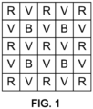
- the sensor generating the initial image may, for example, have a Bayer configuration, as shown in figure 1 , in the RGB color space.
- Each green pixel is represented by the letter "V”
- each red pixel is represented by the letter "R”
- each blue pixel is represented by the letter "B”.
- the components of the color space are red, green, and blue. 50% of the pixels correspond to the green spectral band, 25% of the pixels correspond to the red spectral band, and 25% of the pixels correspond to the blue spectral band.
- the pixels are arranged so that in a square of two pixels on a side, the two pixels on one diagonal correspond to the green spectral band while the other diagonal includes a red pixel and a blue pixel.
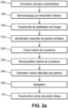
- the demosaicing method comprises for example a preliminary demosaicing by linear interpolation 100 of the initial image, making it possible to calculate intermediate spectral bands.
- the spectral bands correspond to the RGB color space, it is a question of associating with each pixel the two missing spectral bands among red, green and blue.
- the intermediate spectral bands are here an intermediate calculation means.
- This demosaicing by linear interpolation 100 can be chosen from demosaicing methods known to those skilled in the art.
- the demosaicing by linear interpolation can be implemented by means of the Hamilton-Adams algorithm, as described in the patent US5,652,621 .
- the method according to the invention then comprises a step 105 of noise variance stabilization transformation, applied to the pixels of the initial spectral bands, such as for example an Anscombe transform.
- the transformed image designated as a stabilized image, will thus have a regular and equal variance pixel by pixel, allowing a more stable and more precise calculation of similar patches.
- the stabilized image will also allow Wiener filtering to be performed, which relies on a local estimate of the noise variance per pixel, to calculate the estimate of similar patches.
- the calculation of the distance between patches can be considered independently per band or preferably in a multi-band manner, the covariance matrix then being calculated using all available phasings.
- the demosaicing method may further comprise a denoising treatment 200 applied at the output of the noise variance stabilization transformation 105 to obtain the stabilized image.
- the estimation of the local noise, during denoising, is advantageously improved thanks to the prior application of the variance regularization transformation.
- the estimated noise model of the detectors is for example used to manage all the bands jointly and ensure the estimation of the local noise of the patches, avoiding introducing possible artifacts into the image.
- This denoising treatment 200 can be chosen from among the denoising treatments known to those skilled in the art, such as for example an NL-Bayes type algorithm, as described in the article by M. Lebrun et al., “Implementation of the “Non-Local Bayes” (NL-Bayes) Image Denoising Algorithm ".
- the NL-Bayes denoising algorithm includes for example the repetition twice in a row of an identification of a set of similar patches of the image for the calculation of a covariance matrix of the set of similar patches, an estimation of a denoised version, from the covariance matrix and an aggregation to obtain a denoised image.
- the denoising is for example implemented twice in a row, the first time on the image obtained at the end of the demosaicing by linear interpolation and the second time on the denoised image.
- the denoising algorithm for example, performs patch-based processing of the image.
- a patch is a piece of the image that is square in shape and comprises a subset of pixels of the image.
- a patch may comprise, for example, between 2 and 10 pixels on a side and typically comprises between 3 and 5.
- a patch of k 5 pixels on a side is used as an example in the present description.
- the demosaicing method then comprises, for example, a set of steps implemented on at least one patch of the image and preferably on all the patches of the image considered successively.
- Reference patches are for example determined in advance and produce overlaps between two successive patches, so as to cover the entire image.
- the reference patches may for example be contiguous or not.
- the contiguous reference patches may for example overlap or not.
- the non-contiguous reference patches may for example be more or less spaced from each other.
- an uncovered area of the image is for example less than 50% of the image or even less than 25% of the image, or even less than 5% of the image.
- the choice of the proportion of the image covered by the reference patches and their possible overlap will be optimized according to the use cases.
- the proportion of the image, covered by the reference patches is for example between 50% and 100%.
- a step 310 is carried out for identifying a set of patches similar to the image to the reference patch.
- the step 310 for identifying a set of patches of the image similar to the patch considered can be implemented by calculating a distance between the patch considered and each of the patches of the image belonging to a neighborhood of the patch considered, the neighborhood being defined as a portion of the image of size n x n, where n is a number of pixels strictly greater than the number of pixels k on one side of a patch, and less than or equal to the number of pixels on a smaller side of the image.
- the distance can be calculated in native radiometry, that is, from the initial spectral bands in the initial image.
- the distance can also be calculated from the transformed spectral bands.
- d P Q ⁇ N P i , N ⁇ Q i , N 2 / Nk 2
- the distance can be calculated over the entire set of P and Q patches concerned or only a portion of them, for example a horizontal or vertical strip.
- the distance can be calculated in native radiometry or in the transformed image, i.e. from the initial spectral bands in the initial image or from the transformed initial spectral bands.
- the initial image may be pre-converted, before the noise variance stabilization transformation, during a step 205 into another color space, and the normalized quadratic distance may be calculated in this space.
- the initial image may be converted into the YUV domain according to a transformation known to those skilled in the art.
- the normalized quadratic distance may be calculated on the Y luminance component alone.
- the initial image will for example be converted before the linear interpolation demosaicing step 100, as shown in Figure 2a Or 2b .
- the original image can also be converted before the noise variance stabilization transformation, but after step 100 of linear interpolation demosaicing.
- the distance is for example compared to a determined threshold, below which the patches are considered similar.
- the distance is preferably calculated from a transformed image, the threshold being thus directly linked to the local noise, which allows a more efficient denoising.
- a minimum number of similar patches corresponding to the calculated minimum distances can also be provided.
- a minimum number of similar patches can also be provided corresponding to the calculated minimum distances to which are added the patches whose distance is less than the determined threshold.
- the identification of a set of patches similar to the patch considered can comprise the application of a principal component analysis of the image in native, transformed or converted coordinates, and the calculation of a distance (e.g. Euclidean) on the components of greatest weight resulting from this analysis.
- a distance e.g. Euclidean
- a determination of similar patches can be carried out and stored during a prior denoising step.
- the demosaicing method comprises a following step 320 of calculating a covariance matrix of the set of patches similar to the reference patch.
- the covariance matrix can be calculated on the pixel values of the patches in the transformed initial spectral bands represented in the initial stabilized image.
- the covariance matrix can also be calculated on the pixels of an intermediate image obtained by linear interpolation demosaicing, as shown in Figure 2a and possibly supplemented by noise reduction, as shown in figure 2b .
- a covariance matrix, calculated during a previous processing, can possibly be reused.
- Each patch of k pixels on a side in the initial image is represented as a vector whose first k 2 terms correspond to a spectral band, by example the color red, the next k 2 terms correspond to another spectral band, for example the color green, and the last k 2 terms correspond to a third spectral band, for example the color blue.
- the covariance matrix therefore quantifies the covariance of the pixel values of similar patches.
- the available character of a pixel i.e. having a transformed initial spectral band, or the missing character of a pixel, i.e. not having an initial spectral band
- the locations of the pixels having an available or missing character depend on the phasing of the patch.
- To determine the phasing of a patch it is necessary to consider the location on the matrix sensor of a corresponding patch in the initial image. In the case of a Bayer pattern, for example, there are four possible phasings, two examples of which are shown in the Figures 3a And 3b .
- the pixels having an initial value according to the respective red, green or blue component are represented respectively by the letter R, G, B.
- Figure 3a corresponds to a phasing where the pixel located at the top left of the patch is expressed in the green component of the original image
- the figure 3b corresponds to a phasing where the pixel located at the top left of the patch is the pixel expressed in the red component.
- the demosaicing method then comprises in step 330, for each similar patch of said set of similar patches, a calculation of estimates of the interpolated spectral bands, as a function of a block decomposition of the covariance matrix, where the decomposition into four blocks is a function of the phasing of each similar patch.
- the patch will be set to the average value y m similar patches.
- the demosaicing method then comprises an aggregation step 350 in which estimates of the interpolated spectral bands for pixels of patches belonging to different sets of similar patches in relation to different reference patches.
- Aggregation means the combination of different measurements into a single variable, either by simple addition of the values obtained, or by addition of the weighted values.
- the aggregation is implemented for example by calculating an average of the estimates made for a pixel and a component.
- the set of interpolated spectral bands is thus obtained.
- a step 110 of inverse transformation of the pixels of the transformed initial spectral bands is then executed to reestablish the pixels of the spectral bands generated in the initial image.
- the demosaicized image according to the invention has improved quality and a significant reduction or even absence of iridescence, particularly for applications requiring high altitude observation such as earth observation.
- ⁇ dd denoise is the block of the covariance matrix calculated on the available denoised data
- I is the identity matrix
- ⁇ 2 is the variance of the noise. It can be shown that ⁇ md is unchanged in this case.
- x m y ⁇ m + ⁇ md ⁇ dd denoise + ⁇ 2 I ⁇ 1 y d ⁇ y ⁇ d
Landscapes
- Physics & Mathematics (AREA)
- General Physics & Mathematics (AREA)
- Engineering & Computer Science (AREA)
- Theoretical Computer Science (AREA)
- Image Processing (AREA)
Claims (16)
- Verfahren zur Durchführung einer Demosaikierung , das auf ein Anfangsbild, dessen Pixel jeweils einem Anfangsspektralband entsprechen, angewendet wird, um ein in mehrere Spektralbänder demosaikiertes Bild zu gewinnen, dessen Pixel jeweils dem Anfangsspektralband oder einem interpolierten Spektralband entsprechen,
dadurch gekennzeichnet, dass es aufweist:- eine Stabilisationstransformation der Varianz des Rauschens, die auf Pixel der Anfangsspektralbänder angewendet wird,- auf der Basis von mehreren vorgegebenen Referenzbereichen und für jeden Referenzbereich der mehreren Referenzbereiche:* eine Bestimmung (310) einer Gesamtheit von Bereichen, die dem Referenzbereich ähnlich sind, durch Auswerten der Pixel mindestens eines der transformierten Anfangsspektralbänder* eine Bestimmung (320) einer Kovarianzmatrix der Gesamtheit ähnlicher Bereiche und* für jeden ähnlichen Bereich der Gesamtheit ähnlicher Bereiche, eine Berechnung von Schätzungen der interpolierten Spektralbänder abhängig von einer blockweisen Zerlegung der Kovarianzmatrix (340), wobei die Zerlegung in vier Blöcke abhängig von der Phase jedes ähnlichen Bereichs ist,- eine Bestimmung von interpolierten Spektralbändern durch eine Aufsummierung (350) der Schätzungen der interpolierten Spektralbänder, wobei man die Schätzungen der interpolierten Spektralbänder für jedes Pixel aufsummiert, und- eine zur Stabilisationstransformation inverse Transformation, die auf die Pixel der transformierten Anfangsspektralbänder angewendet wird. - Verfahren zur Durchführung einer Demosaikierung nach Anspruch 1, in welchem die Stabilisationstransformation der Varianz des Rauschens in Abhängigkeit von einem Rauschmodell erfolgt, das dem Detektor eigen ist.
- Verfahren nach Anspruch 1 oder 2, in welchem die vorgegebenen Referenzbereiche derart verteilt sind, um einen bestimmten Anteil des Bilds abzudecken.
- Verfahren nach einem der Ansprüche 1 bis 3, in welchem bei der Bestimmung der Kovarianzmatrix der Gesamtheit ähnlicher Bereiche die ähnlichen Bereiche transformierte Anfangsspektralbänder und Zwischenspektralbänder aufweisen, wobei diese Zwischenspektralbänder aus einer vorausgehenden Durchführung einer Demosaikierung durch lineare Interpolation stammen, die auf das stabilisierte Anfangsbild angewandt worden ist.
- Verfahren nach dem vorstehenden Anspruch, in welchem die Bestimmung (310) der Gesamtheit von Bereichen, die dem jeweiligen Referenzbereich ähnlich sind, mithilfe einer Ähnlichkeitsfunktion bestimmt wird, die auf ein Zwischenbild angewendet wird, das aus der vorausgehenden Durchführung einer Demosaikierung durch lineare Interpolation des stabilisierten Anfangsbilds resultiert, wobei die Ähnlichkeitsfunktion ein oder mehrere der Spektralbänder des Zwischenbilds verwendet.
- Verfahren nach einem der Ansprüche 1 bis 3, in welchem bei der Bestimmung der Kovarianzmatrix der Gesamtheit ähnlicher Bereiche die ähnlichen Bereiche transformierte Anfangsspektralbänder und Zwischenspektralbänder aufweisen, wobei diese Zwischenspektralbänder aus einer vorausgehenden Durchführung einer Demosaikierung durch lineare Interpolation und aus einer auf das stabilisierte Anfangsbild angewandten vorausgehenden Entrauschung stammen.
- Verfahren nach dem vorstehenden Anspruch, in welchem die Bestimmung (310) der Gesamtheit von Bereichen, die dem jeweiligen Referenzbereich ähnlich sind, mithilfe einer Ähnlichkeitsfunktion bestimmt wird, die auf ein Zwischenbild angewendet wird, das aus der vorausgehenden Durchführung einer Demosaikierung durch lineare Interpolation (100) und aus der vorausgehenden Entrauschung des stabilisierten Anfangsbilds resultiert, wobei die Ähnlichkeitsfunktion ein oder mehrere der Spektralbänder des Zwischenbilds verwendet.
- Verfahren nach Anspruch 6 oder 7, wobei die Entrauschung aus einer lokalen Entrauschungsfunktion besteht, die auf jeden Bereich angewendet wird und abhängig von der Gesamtheit der Bereiche ist, die dem betrachteten Bereich ähnlich sind.
- Verfahren nach einem der Ansprüche 1 bis 8, in welchem die Spektralbänder dem Farbraum RGB oder YUV entsprechen.
- Verfahren nach einem der Ansprüche 1 bis 9, in welchem die Spektralbänder dem Farbraum RGB entsprechen und die Pixel des stabilisierten Anfangsbilds gemäß einem Bayer-Motiv organisiert sind.
- Verfahren nach einem der vorstehenden Ansprüche, in welchem die Aufsummierung (350) der Schätzungen der interpolierten Spektralbänder durch eine Berechnung eines Mittelwerts dieser Schätzungen der interpolierten Spektralbänder erfolgt.
- Verfahren nach einem der vorstehenden Ansprüche, in welchem die Zerlegung in vier Blöcke in Abhängigkeit von der Phase des ähnlichen Bereichs abhängig von dem Paar (L, C) ist, das dem L-ten Pixel und dem C-ten Pixel des ähnlichen Bereichs entspricht, wobei jeder Wert der Matrix an der Zeile L und der Spalte C- einem ersten Block Σ dd zugeordnet wird, wenn es sich um ein Pixel L, das einem transformierten Anfangsspektralband entspricht, und ein Pixel C, das einem transformierten Anfangsspektralband entspricht, handelt,- einem zweiten Block Σmd zugeordnet wird, wenn es sich um ein Pixel L, das nicht einem Anfangsspektralband entspricht, und ein Pixel C, das einem transformierten Anfangsspektralband entspricht, handelt,- einem dritten Block Σdm zugeordnet wird, wenn es sich um ein Pixel L, das einem transformierten Anfangsspektralband entspricht, und ein Pixel C, das nicht einem Anfangsspektralband entspricht, handelt, oder- einem vierten Block Σmm zugeordnet wird, wenn es sich um ein Pixel L, das nicht einem Anfangsspektralband entspricht, und ein Pixel C, das nicht einem Anfangsspektralband entspricht, handelt.
- Verfahren nach dem vorstehenden Anspruch, in welchem für jeden ähnlichen Bereich in der Gesamtheit ähnlicher Bereiche die Berechnung der Schätzungen der interpolierten Spektralbänder wie folgt durchgeführt wird:
 - xm der Vektor der Schätzungen der interpolierten Spektralbänder des ähnlichen Bereichs ist,-
y m der Vektor der Mittelwerte der Pixel der Bereiche der Gesamtheit ähnlicher Bereiche ist, wobei man die Pixel betrachtet, die einem Anfangsspektralband nicht entsprechen,- yd der Vektor der Pixel ist, die einem transformierten Anfangsspektralband in dem ähnlichen Bereich entsprechen,- yd der Vektor der Mittelwerte der Pixel der Bereiche der Gesamtheit ähnlicher Bereiche ist, wobei man die Pixel betrachtet, die einem transformierten Anfangsspektralband entsprechen,- - Σmd der zweite Block ist.
 - Verfahren nach dem vorstehenden Anspruch, in welchem bei der Berechnung der Schätzungen der interpolierten Spektralbänder für die ähnlichen Bereiche, die eine gleiche Phase haben, eine gleiche Zerlegung der Kovarianzmatrix in Blöcke stattfindet, die gespeichert werden und für alle diese ähnlichen Bereiche, die die gleiche Phase haben, wieder verwendet wird.
- Computerprogrammprodukt, aufweisend Code-Befehle zum Durchführen des Verfahrens nach einem der vorstehenden Ansprüche, wenn es von einem Rechner ausgeführt wird.
- Bildverarbeitungsvorrichtung, aufweisend einen Rechner (11), dadurch gekennzeichnet, dass sie zum Durchführen des Verfahrens nach einem der Ansprüche 1 bis 14 konfiguriert ist.
Applications Claiming Priority (2)
| Application Number | Priority Date | Filing Date | Title |
|---|---|---|---|
| FR2203915A FR3135155B1 (fr) | 2022-04-27 | 2022-04-27 | Procédé de démosaïquage non-local d’une image et dispositif associé |
| PCT/EP2023/060515 WO2023208783A1 (fr) | 2022-04-27 | 2023-04-21 | Procédé de démosaïquage non-local d'une image et dispositif associé |
Publications (3)
| Publication Number | Publication Date |
|---|---|
| EP4364083A1 EP4364083A1 (de) | 2024-05-08 |
| EP4364083B1 true EP4364083B1 (de) | 2024-11-27 |
| EP4364083C0 EP4364083C0 (de) | 2024-11-27 |
Family
ID=82694222
Family Applications (1)
| Application Number | Title | Priority Date | Filing Date |
|---|---|---|---|
| EP23721393.9A Active EP4364083B1 (de) | 2022-04-27 | 2023-04-21 | Verfahren zur durchführung einer nichtlokalen demosaicing eines bildes und zugehörige vorrichtung |
Country Status (5)
| Country | Link |
|---|---|
| US (1) | US12347063B2 (de) |
| EP (1) | EP4364083B1 (de) |
| ES (1) | ES3000763T3 (de) |
| FR (1) | FR3135155B1 (de) |
| WO (1) | WO2023208783A1 (de) |
Family Cites Families (16)
| Publication number | Priority date | Publication date | Assignee | Title |
|---|---|---|---|---|
| US5629734A (en) | 1995-03-17 | 1997-05-13 | Eastman Kodak Company | Adaptive color plan interpolation in single sensor color electronic camera |
| US5652621A (en) | 1996-02-23 | 1997-07-29 | Eastman Kodak Company | Adaptive color plane interpolation in single sensor color electronic camera |
| US7030917B2 (en) * | 1998-10-23 | 2006-04-18 | Hewlett-Packard Development Company, L.P. | Image demosaicing and enhancement system |
| US6404918B1 (en) * | 1999-04-30 | 2002-06-11 | Hewlett-Packard Company | Image demosaicing method utilizing directional smoothing |
| WO2008067479A1 (en) * | 2006-11-29 | 2008-06-05 | President And Fellows Of Harvard College | A framework for wavelet-based analysis and processing of color filter array images with applications to denoising and demosaicing |
| US20090295934A1 (en) * | 2008-05-27 | 2009-12-03 | The Hong Kong University Of Science And Technology | Color demosaicking using direction similarity in color difference spaces |
| WO2012166840A2 (en) * | 2011-06-01 | 2012-12-06 | The Board Of Trustees Of The Leland Stanford Junior University | Learning of image processing pipeline for digital imaging devices |
| US9207759B1 (en) * | 2012-10-08 | 2015-12-08 | Edge3 Technologies, Inc. | Method and apparatus for generating depth map from monochrome microlens and imager arrays |
| US9582853B1 (en) * | 2015-08-03 | 2017-02-28 | Intel Corporation | Method and system of demosaicing bayer-type image data for image processing |
| EP3522106A1 (de) * | 2018-01-31 | 2019-08-07 | InterDigital CE Patent Holdings | Filteranordnung, die eine einfache entmosaikierung ermöglicht |
| US11525732B2 (en) * | 2018-03-18 | 2022-12-13 | Unispectral Ltd. | Generating narrow-band spectral images from broad-band spectral images |
| JP2021097254A (ja) * | 2018-03-23 | 2021-06-24 | ソニーグループ株式会社 | 信号処理装置、信号処理方法、撮像装置および医療用撮像装置 |
| JP7349806B2 (ja) * | 2018-03-28 | 2023-09-25 | ブラックマジック デザイン ピーティーワイ リミテッド | 画像処理方法及びフィルタアレイ |
| EP4120690B1 (de) * | 2020-08-29 | 2025-09-10 | Shokz Hearing Pte. Ltd. | Verfahren und system zur erzeugung einer schwingungsübertragungsfunktion |
| KR102819572B1 (ko) * | 2020-09-22 | 2025-06-12 | 삼성전자주식회사 | 컬러 분해 방법 및 이를 이용한 심층 학습 기반의 디모자이킹 방법 |
| KR102797187B1 (ko) * | 2020-10-23 | 2025-04-18 | 삼성전자주식회사 | 심층 학습 기반의 디모자이킹 방법 및 디모자이킹 장치 |
-
2022
- 2022-04-27 FR FR2203915A patent/FR3135155B1/fr active Active
-
2023
- 2023-04-21 ES ES23721393T patent/ES3000763T3/es active Active
- 2023-04-21 EP EP23721393.9A patent/EP4364083B1/de active Active
- 2023-04-21 WO PCT/EP2023/060515 patent/WO2023208783A1/fr not_active Ceased
- 2023-04-21 US US18/859,833 patent/US12347063B2/en active Active
Also Published As
| Publication number | Publication date |
|---|---|
| WO2023208783A1 (fr) | 2023-11-02 |
| ES3000763T3 (en) | 2025-03-03 |
| FR3135155B1 (fr) | 2024-04-19 |
| US12347063B2 (en) | 2025-07-01 |
| FR3135155A1 (fr) | 2023-11-03 |
| US20250173818A1 (en) | 2025-05-29 |
| EP4364083A1 (de) | 2024-05-08 |
| EP4364083C0 (de) | 2024-11-27 |
Similar Documents
| Publication | Publication Date | Title |
|---|---|---|
| EP4046128B1 (de) | Verfahren für nicht-lokales bild-demosaicing und zugehörige vorrichtung | |
| US11676248B2 (en) | Deep residual network for color filter array image denoising | |
| Pei et al. | Nighttime haze removal using color transfer pre-processing and dark channel prior | |
| EP1482724B1 (de) | Bildverarbeitungsverfahren für numerische Bilder mit Belichtungskorrektur durch Erkennung von Hautbereichen des Gegenstandes | |
| EP2426639B1 (de) | Demosaicing-Verfahren für ein digitales Rohbild, entsprechendes Computerprogramm und entsprechende Bild- oder Grafikerzeugungsschaltung | |
| CN109889800B (zh) | 图像增强方法和装置、电子设备、存储介质 | |
| Zhou et al. | Deep residual network for joint demosaicing and super-resolution | |
| KR102466061B1 (ko) | 계층적 생성 적대 네트워크를 이용한 노이즈 제거 장치 및 그 방법 | |
| WO2021110262A1 (en) | Noise reconstruction for image denoising | |
| EP3891693A1 (de) | Bildprozessor | |
| FR3059804A1 (fr) | Systeme de traitement d'images | |
| CA3043090C (fr) | Procede de reconnaissance de caracteres | |
| CN117372564B (zh) | 一种重构多光谱图像的方法、系统及存储介质 | |
| FR3081244A1 (fr) | Procede de reconnaissance de caracteres | |
| EP2294552B1 (de) | Verbesserte einrichtung zum verarbeiten von bildern | |
| Sadeghipoor et al. | Optimum spectral sensitivity functions for single sensor color imaging | |
| EP3206161B1 (de) | Verfahren zur bestimmung eines farbwerts eines objekts auf einem bild | |
| EP4364083A1 (de) | Verfahren zur durchführung einer nichtlokalen demosaicing eines bildes und zugehörige vorrichtung | |
| Yamaguchi et al. | Image demosaicking via chrominance images with parallel convolutional neural networks | |
| Saito et al. | Demosaicing approach based on extended color total-variation regularization | |
| EP3535730B1 (de) | Verfahren und vorrichtung zur wiederherstellung digitaler bilder | |
| BE1021013B1 (fr) | Procede et systeme pour ameliorer la qualite d'images en couleur. | |
| US20240087128A1 (en) | Adaptive auto white balancing | |
| FR3143162A1 (fr) | Procédé et dispositif de dématriçage | |
| Hast et al. | Retrospective illumination correction of greyscale historical aerial photos |
Legal Events
| Date | Code | Title | Description |
|---|---|---|---|
| STAA | Information on the status of an ep patent application or granted ep patent |
Free format text: STATUS: UNKNOWN |
|
| STAA | Information on the status of an ep patent application or granted ep patent |
Free format text: STATUS: THE INTERNATIONAL PUBLICATION HAS BEEN MADE |
|
| PUAI | Public reference made under article 153(3) epc to a published international application that has entered the european phase |
Free format text: ORIGINAL CODE: 0009012 |
|
| STAA | Information on the status of an ep patent application or granted ep patent |
Free format text: STATUS: REQUEST FOR EXAMINATION WAS MADE |
|
| 17P | Request for examination filed |
Effective date: 20240130 |
|
| AK | Designated contracting states |
Kind code of ref document: A1 Designated state(s): AL AT BE BG CH CY CZ DE DK EE ES FI FR GB GR HR HU IE IS IT LI LT LU LV MC ME MK MT NL NO PL PT RO RS SE SI SK SM TR |
|
| GRAP | Despatch of communication of intention to grant a patent |
Free format text: ORIGINAL CODE: EPIDOSNIGR1 |
|
| STAA | Information on the status of an ep patent application or granted ep patent |
Free format text: STATUS: GRANT OF PATENT IS INTENDED |
|
| INTG | Intention to grant announced |
Effective date: 20240702 |
|
| GRAS | Grant fee paid |
Free format text: ORIGINAL CODE: EPIDOSNIGR3 |
|
| GRAA | (expected) grant |
Free format text: ORIGINAL CODE: 0009210 |
|
| STAA | Information on the status of an ep patent application or granted ep patent |
Free format text: STATUS: THE PATENT HAS BEEN GRANTED |
|
| AK | Designated contracting states |
Kind code of ref document: B1 Designated state(s): AL AT BE BG CH CY CZ DE DK EE ES FI FR GB GR HR HU IE IS IT LI LT LU LV MC ME MK MT NL NO PL PT RO RS SE SI SK SM TR |
|
| DAV | Request for validation of the european patent (deleted) | ||
| DAX | Request for extension of the european patent (deleted) | ||
| REG | Reference to a national code |
Ref country code: GB Ref legal event code: FG4D Free format text: NOT ENGLISH |
|
| REG | Reference to a national code |
Ref country code: CH Ref legal event code: EP |
|
| REG | Reference to a national code |
Ref country code: IE Ref legal event code: FG4D Free format text: LANGUAGE OF EP DOCUMENT: FRENCH |
|
| REG | Reference to a national code |
Ref country code: DE Ref legal event code: R096 Ref document number: 602023001183 Country of ref document: DE |
|
| U01 | Request for unitary effect filed |
Effective date: 20241217 |
|
| U07 | Unitary effect registered |
Designated state(s): AT BE BG DE DK EE FI FR IT LT LU LV MT NL PT RO SE SI Effective date: 20250110 |
|
| REG | Reference to a national code |
Ref country code: ES Ref legal event code: FG2A Ref document number: 3000763 Country of ref document: ES Kind code of ref document: T3 Effective date: 20250303 |
|
| PG25 | Lapsed in a contracting state [announced via postgrant information from national office to epo] |
Ref country code: HR Free format text: LAPSE BECAUSE OF FAILURE TO SUBMIT A TRANSLATION OF THE DESCRIPTION OR TO PAY THE FEE WITHIN THE PRESCRIBED TIME-LIMIT Effective date: 20241127 Ref country code: IS Free format text: LAPSE BECAUSE OF FAILURE TO SUBMIT A TRANSLATION OF THE DESCRIPTION OR TO PAY THE FEE WITHIN THE PRESCRIBED TIME-LIMIT Effective date: 20250327 |
|
| PG25 | Lapsed in a contracting state [announced via postgrant information from national office to epo] |
Ref country code: NO Free format text: LAPSE BECAUSE OF FAILURE TO SUBMIT A TRANSLATION OF THE DESCRIPTION OR TO PAY THE FEE WITHIN THE PRESCRIBED TIME-LIMIT Effective date: 20250227 |
|
| PG25 | Lapsed in a contracting state [announced via postgrant information from national office to epo] |
Ref country code: GR Free format text: LAPSE BECAUSE OF FAILURE TO SUBMIT A TRANSLATION OF THE DESCRIPTION OR TO PAY THE FEE WITHIN THE PRESCRIBED TIME-LIMIT Effective date: 20250228 |
|
| PG25 | Lapsed in a contracting state [announced via postgrant information from national office to epo] |
Ref country code: PL Free format text: LAPSE BECAUSE OF FAILURE TO SUBMIT A TRANSLATION OF THE DESCRIPTION OR TO PAY THE FEE WITHIN THE PRESCRIBED TIME-LIMIT Effective date: 20241127 |
|
| PG25 | Lapsed in a contracting state [announced via postgrant information from national office to epo] |
Ref country code: RS Free format text: LAPSE BECAUSE OF FAILURE TO SUBMIT A TRANSLATION OF THE DESCRIPTION OR TO PAY THE FEE WITHIN THE PRESCRIBED TIME-LIMIT Effective date: 20250227 |
|
| U20 | Renewal fee for the european patent with unitary effect paid |
Year of fee payment: 3 Effective date: 20250321 |
|
| PG25 | Lapsed in a contracting state [announced via postgrant information from national office to epo] |
Ref country code: SM Free format text: LAPSE BECAUSE OF FAILURE TO SUBMIT A TRANSLATION OF THE DESCRIPTION OR TO PAY THE FEE WITHIN THE PRESCRIBED TIME-LIMIT Effective date: 20241127 |
|
| PGFP | Annual fee paid to national office [announced via postgrant information from national office to epo] |
Ref country code: ES Payment date: 20250512 Year of fee payment: 3 |
|
| PG25 | Lapsed in a contracting state [announced via postgrant information from national office to epo] |
Ref country code: SK Free format text: LAPSE BECAUSE OF FAILURE TO SUBMIT A TRANSLATION OF THE DESCRIPTION OR TO PAY THE FEE WITHIN THE PRESCRIBED TIME-LIMIT Effective date: 20241127 |
|
| PG25 | Lapsed in a contracting state [announced via postgrant information from national office to epo] |
Ref country code: CZ Free format text: LAPSE BECAUSE OF FAILURE TO SUBMIT A TRANSLATION OF THE DESCRIPTION OR TO PAY THE FEE WITHIN THE PRESCRIBED TIME-LIMIT Effective date: 20241127 |
|
| PLBE | No opposition filed within time limit |
Free format text: ORIGINAL CODE: 0009261 |
|
| STAA | Information on the status of an ep patent application or granted ep patent |
Free format text: STATUS: NO OPPOSITION FILED WITHIN TIME LIMIT |
|
| 26N | No opposition filed |
Effective date: 20250828 |
|
| PG25 | Lapsed in a contracting state [announced via postgrant information from national office to epo] |
Ref country code: MC Free format text: LAPSE BECAUSE OF FAILURE TO SUBMIT A TRANSLATION OF THE DESCRIPTION OR TO PAY THE FEE WITHIN THE PRESCRIBED TIME-LIMIT Effective date: 20241127 |
|
| PG25 | Lapsed in a contracting state [announced via postgrant information from national office to epo] |
Ref country code: IE Free format text: LAPSE BECAUSE OF NON-PAYMENT OF DUE FEES Effective date: 20250421 |
|
| U20 | Renewal fee for the european patent with unitary effect paid |
Year of fee payment: 4 Effective date: 20260323 |