EP4363771B1 - Integrierte festkörperlichtquelle und leuchtstoffmodul - Google Patents
Integrierte festkörperlichtquelle und leuchtstoffmodul Download PDFInfo
- Publication number
- EP4363771B1 EP4363771B1 EP22737798.3A EP22737798A EP4363771B1 EP 4363771 B1 EP4363771 B1 EP 4363771B1 EP 22737798 A EP22737798 A EP 22737798A EP 4363771 B1 EP4363771 B1 EP 4363771B1
- Authority
- EP
- European Patent Office
- Prior art keywords
- light
- window element
- element part
- light generating
- luminescent material
- Prior art date
- Legal status (The legal status is an assumption and is not a legal conclusion. Google has not performed a legal analysis and makes no representation as to the accuracy of the status listed.)
- Active
Links
Images
Classifications
-
- F—MECHANICAL ENGINEERING; LIGHTING; HEATING; WEAPONS; BLASTING
- F21—LIGHTING
- F21V—FUNCTIONAL FEATURES OR DETAILS OF LIGHTING DEVICES OR SYSTEMS THEREOF; STRUCTURAL COMBINATIONS OF LIGHTING DEVICES WITH OTHER ARTICLES, NOT OTHERWISE PROVIDED FOR
- F21V29/00—Protecting lighting devices from thermal damage; Cooling or heating arrangements specially adapted for lighting devices or systems
- F21V29/50—Cooling arrangements
- F21V29/502—Cooling arrangements characterised by the adaptation for cooling of specific components
- F21V29/506—Cooling arrangements characterised by the adaptation for cooling of specific components of globes, bowls or cover glasses
-
- F—MECHANICAL ENGINEERING; LIGHTING; HEATING; WEAPONS; BLASTING
- F21—LIGHTING
- F21K—NON-ELECTRIC LIGHT SOURCES USING LUMINESCENCE; LIGHT SOURCES USING ELECTROCHEMILUMINESCENCE; LIGHT SOURCES USING CHARGES OF COMBUSTIBLE MATERIAL; LIGHT SOURCES USING SEMICONDUCTOR DEVICES AS LIGHT-GENERATING ELEMENTS; LIGHT SOURCES NOT OTHERWISE PROVIDED FOR
- F21K9/00—Light sources using semiconductor devices as light-generating elements, e.g. using light-emitting diodes [LED] or lasers
- F21K9/60—Optical arrangements integrated in the light source, e.g. for improving the colour rendering index or the light extraction
- F21K9/62—Optical arrangements integrated in the light source, e.g. for improving the colour rendering index or the light extraction using mixing chambers, e.g. housings with reflective walls
-
- F—MECHANICAL ENGINEERING; LIGHTING; HEATING; WEAPONS; BLASTING
- F21—LIGHTING
- F21K—NON-ELECTRIC LIGHT SOURCES USING LUMINESCENCE; LIGHT SOURCES USING ELECTROCHEMILUMINESCENCE; LIGHT SOURCES USING CHARGES OF COMBUSTIBLE MATERIAL; LIGHT SOURCES USING SEMICONDUCTOR DEVICES AS LIGHT-GENERATING ELEMENTS; LIGHT SOURCES NOT OTHERWISE PROVIDED FOR
- F21K9/00—Light sources using semiconductor devices as light-generating elements, e.g. using light-emitting diodes [LED] or lasers
- F21K9/60—Optical arrangements integrated in the light source, e.g. for improving the colour rendering index or the light extraction
- F21K9/64—Optical arrangements integrated in the light source, e.g. for improving the colour rendering index or the light extraction using wavelength conversion means distinct or spaced from the light-generating element, e.g. a remote phosphor layer
-
- F—MECHANICAL ENGINEERING; LIGHTING; HEATING; WEAPONS; BLASTING
- F21—LIGHTING
- F21V—FUNCTIONAL FEATURES OR DETAILS OF LIGHTING DEVICES OR SYSTEMS THEREOF; STRUCTURAL COMBINATIONS OF LIGHTING DEVICES WITH OTHER ARTICLES, NOT OTHERWISE PROVIDED FOR
- F21V9/00—Elements for modifying spectral properties, polarisation or intensity of the light emitted, e.g. filters
- F21V9/30—Elements containing photoluminescent material distinct from or spaced from the light source
-
- H—ELECTRICITY
- H05—ELECTRIC TECHNIQUES NOT OTHERWISE PROVIDED FOR
- H05B—ELECTRIC HEATING; ELECTRIC LIGHT SOURCES NOT OTHERWISE PROVIDED FOR; CIRCUIT ARRANGEMENTS FOR ELECTRIC LIGHT SOURCES, IN GENERAL
- H05B47/00—Circuit arrangements for operating light sources in general, i.e. where the type of light source is not relevant
- H05B47/10—Controlling the light source
- H05B47/17—Operational modes, e.g. switching from manual to automatic mode or prohibiting specific operations
-
- F—MECHANICAL ENGINEERING; LIGHTING; HEATING; WEAPONS; BLASTING
- F21—LIGHTING
- F21Y—INDEXING SCHEME ASSOCIATED WITH SUBCLASSES F21K, F21L, F21S and F21V, RELATING TO THE FORM OR THE KIND OF THE LIGHT SOURCES OR OF THE COLOUR OF THE LIGHT EMITTED
- F21Y2113/00—Combination of light sources
- F21Y2113/20—Combination of light sources of different form
-
- F—MECHANICAL ENGINEERING; LIGHTING; HEATING; WEAPONS; BLASTING
- F21—LIGHTING
- F21Y—INDEXING SCHEME ASSOCIATED WITH SUBCLASSES F21K, F21L, F21S and F21V, RELATING TO THE FORM OR THE KIND OF THE LIGHT SOURCES OR OF THE COLOUR OF THE LIGHT EMITTED
- F21Y2115/00—Light-generating elements of semiconductor light sources
- F21Y2115/10—Light-emitting diodes [LED]
-
- F—MECHANICAL ENGINEERING; LIGHTING; HEATING; WEAPONS; BLASTING
- F21—LIGHTING
- F21Y—INDEXING SCHEME ASSOCIATED WITH SUBCLASSES F21K, F21L, F21S and F21V, RELATING TO THE FORM OR THE KIND OF THE LIGHT SOURCES OR OF THE COLOUR OF THE LIGHT EMITTED
- F21Y2115/00—Light-generating elements of semiconductor light sources
- F21Y2115/30—Semiconductor lasers
-
- G—PHYSICS
- G03—PHOTOGRAPHY; CINEMATOGRAPHY; ANALOGOUS TECHNIQUES USING WAVES OTHER THAN OPTICAL WAVES; ELECTROGRAPHY; HOLOGRAPHY
- G03B—APPARATUS OR ARRANGEMENTS FOR TAKING PHOTOGRAPHS OR FOR PROJECTING OR VIEWING THEM; APPARATUS OR ARRANGEMENTS EMPLOYING ANALOGOUS TECHNIQUES USING WAVES OTHER THAN OPTICAL WAVES; ACCESSORIES THEREFOR
- G03B21/00—Projectors or projection-type viewers; Accessories therefor
- G03B21/14—Details
- G03B21/20—Lamp housings
- G03B21/2006—Lamp housings characterised by the light source
- G03B21/2013—Plural light sources
-
- G—PHYSICS
- G03—PHOTOGRAPHY; CINEMATOGRAPHY; ANALOGOUS TECHNIQUES USING WAVES OTHER THAN OPTICAL WAVES; ELECTROGRAPHY; HOLOGRAPHY
- G03B—APPARATUS OR ARRANGEMENTS FOR TAKING PHOTOGRAPHS OR FOR PROJECTING OR VIEWING THEM; APPARATUS OR ARRANGEMENTS EMPLOYING ANALOGOUS TECHNIQUES USING WAVES OTHER THAN OPTICAL WAVES; ACCESSORIES THEREFOR
- G03B21/00—Projectors or projection-type viewers; Accessories therefor
- G03B21/14—Details
- G03B21/20—Lamp housings
- G03B21/2006—Lamp housings characterised by the light source
- G03B21/2033—LED or laser light sources
- G03B21/204—LED or laser light sources using secondary light emission, e.g. luminescence or fluorescence
Definitions
- the invention relates to a light generating system as well as to a light generating device comprising such system.
- the invention also relates to a method for controlling a beam shape.
- US2018/0347773 describes a light generating device, comprising at least one light emitting diode having a semiconductor layer that emits a first primary light, and having a phosphor layer arranged on the semiconductor layer, and at least one laser for generating at least one laser beam composed of a second primary light, by means of which the phosphor layer is irradiatable, wherein the phosphor layer is configured for at least partly converting the first primary light into at least one first secondary light and for at least partly converting the second primary light into at least one second secondary light.
- the light generating device of US2018/0347773 is configured to dynamically illuminate the phosphor layer by means of the second primary light.
- DE102016201606A1 discloses a lighting device with an LED for emitting LED radiation, a laser for emitting laser radiation and a phosphor element for at least partial conversion of the LED radiation and the laser radiation into a conversion light.
- a lighting device with an LED irradiation surface irradiated with the LED radiation on the irradiation surface of the phosphor element and a laser irradiation surface irradiated with the laser radiation on the irradiation surface of the phosphor element, with at least an overlap in the irradiation surfaces.
- KR 2017 0142760 discloses a light generating system.
- High brightness light sources can be used in applications such as projection, stage-lighting, spot-lighting and automotive lighting.
- laser-phosphor technology can be used wherein a laser provides laser light and e.g. a (remote) phosphor converts laser light into converted light.
- the phosphor may in embodiments be arranged on or inserted in a heatsink for improved thermal management and thus higher brightness.
- the present invention may have as object to overcome or ameliorate at least one of the disadvantages of the prior art, or to provide a useful alternative.
- the invention provides a light generating system (“system") comprising a first light generating device, a second light generating device, and a first luminescent material. Further, the light generating system comprises a window element. Yet further, the light generating system also comprises a light mixing chamber. The first light generating device is configured to provide first device light, in the light mixing chamber. The first light generating device comprises one or more of a laser and a superluminescent diode.
- the second light generating device is configured to generate second device light in the light mixing chamber.
- the second light generating device comprises a solid state light source.
- the light mixing chamber defined by the window element and reflective walls, wherein the reflective walls having an average reflectivity for the second device light of at least 50 %.
- the window element comprises (i) a first window element part comprising the first luminescent material, wherein the first window element part is configured in a light receiving relationship with the first light generating device, and (ii) a second window element part, wherein the second window element part is translucent for the second device light and does not comprise a luminescent material for conversion of the second device light, and wherein the second window element part is configured in a light receiving relationship with the second light generating device.
- the first window element part and the second window element part are configured in thermal contact with each other.
- the first window element part and the second window element part differ in material composition.
- the first luminescent material may be configured to convert at least part of the first device light into first luminescent material light.
- the reflectivity of the second window part is selected from the range of 30 - 70 % for the second device light.
- the invention provides a light generating system comprising a first light generating device, a second light generating device, a first luminescent material, a window element, and a light mixing chamber, wherein: (A) the first light generating device is configured to provide first device light (in the light mixing chamber); wherein the first light generating device comprises one or more of a laser and a superluminescent diode; (B) the second light generating device is configured to generate second device light (in the light mixing chamber); wherein the second light generating device comprises a solid state light source; (C) the light mixing chamber is at defined by the window element and reflective walls, wherein the reflective walls having an average reflectivity for the second device light of at least 50 %.; (D) the window element comprises (i) a first window element part comprising the first luminescent material, wherein the first window element part is configured in a light receiving relationship with the first light generating device, and (ii) a second window element part, wherein the second window element part is translucent for the second
- the first light generating device may be used for providing a narrower beam and/or a more central beam.
- the second light generating device may be used to provide a broader beam and/or a beam at least partially surrounding the narrower beam or a more central beam.
- relatively intense beams may be provided.
- a transmissive mode solution can be provided. In the transmissive mode, it may be relatively easy to have light source light admixed in the luminescent material light, which may be useful for generating the desirable spectral power distribution.
- colors or color points of a first type of light and a second type of light may be different when the respective color points of the first type of light and the second type of light differ with at least 0.01 for u' and/or with at least 0.01 for v', even more especially at least 0.02 for u' and/or with at least 0.02 for v'.
- the respective color points of first type of light and the second type of light may differ with at least 0.03 for u' and/or with at least 0.03 for v'.
- u' and v' are color coordinate of the light in the CIE 1976 UCS (uniform chromaticity scale) diagram.
- the term "light generating device” may refer to one or more light generating devices. Each light generating device may comprise one or more light sources, especially one or more solid state light sources.
- COB especially refers to LED chips in the form of a semiconductor chip that is neither encased nor connected but directly mounted onto a substrate, such as a PCB. Hence, a plurality of light semiconductor light source may be configured on the same substrate.
- a COB is a multi-LED chip configured together as a single lighting module.
- the light source has a light escape surface.
- a light escape surface Referring to conventional light sources such as light bulbs or fluorescent lamps, it may be outer surface of the glass or quartz envelope.
- LED's it may for instance be the LED die, or when a resin is applied to the LED die, the outer surface of the resin. In principle, it may also be the terminal end of a fiber.
- escape surface especially relates to that part of the light source, where the light actually leaves or escapes from the light source.
- the light source is configured to provide a beam of light. This beam of light (thus) escapes from the light exit surface of the light source.
- the term “light source” may refer to a semiconductor light-emitting device, such as a light emitting diode (LEDs), a resonant cavity light emitting diode (RCLED), a vertical cavity laser diode (VCSELs), an edge emitting laser, etc.
- the term “light source” may also refer to an organic light-emitting diode, such as a passive-matrix (PMOLED) or an active-matrix (AMOLED).
- the light source comprises a solid-state light source (such as a LED or laser diode).
- the light source comprises a LED (light emitting diode).
- the terms “light source” or “solid state light source” may also refer to a superluminescent diode (SLED).
- the light source may be configured to provide primary radiation, which is used as such, such as e.g. a blue light source, like a blue LED, or a green light source, such as a green LED, and a red light source, such as a red LED.
- a blue light source like a blue LED
- a green light source such as a green LED
- a red light source such as a red LED.
- Such LEDs which may not comprise a luminescent material (“phosphor”) may be indicated as direct color LEDs.
- the light generating device may comprise a luminescent material.
- the light generating device may comprise a PC LED.
- the light generating device may comprise a direct LED (i.e. no phosphor).
- the light generating device may comprise a laser device, like a laser diode.
- the light generating device may comprise a superluminescent diode.
- the light source may be selected from the group of laser diodes and superluminescent diodes.
- the light source may comprise an LED.
- the light source may especially be configured to generate light source light having an optical axis (O), (a beam shape,) and a spectral power distribution.
- the light source light may in embodiments comprise one or more bands, having band widths as known for lasers.
- the term "light source” may (thus) refer to a light generating element as such, like e.g. a solid state light source, or e.g. to a package of the light generating element, such as a solid state light source, and one or more of a luminescent material comprising element and (other) optics, like a lens, a collimator.
- a light converter element (“converter element” or “converter”) may comprise a luminescent material comprising element. For instance, a solid state light as such, like a blue LED, is a light source.
- a combination of a solid state light source (as light generating element) and a light converter element, such as a blue LED and a light converter element, optically coupled to the solid state light source, may also be a light source.
- a white LED is a light source.
- the term "light source” herein may also refer to a light source comprising a solid state light source, such as an LED or a laser diode or a superluminescent diode.
- the "term light source” may (thus) in embodiments also refer to a light source that is (also) based on conversion of light, such as a light source in combination with a luminescent converter material.
- the term “light source” may also refer to a combination of a LED with a luminescent material configured to convert at least part of the LED radiation, or to a combination of a (diode) laser with a luminescent material configured to convert at least part of the (diode) laser radiation.
- different light sources or “a plurality of different light sources”, and similar phrases, may in embodiments refer to a plurality of solid-state light sources selected from at least two different bins.
- the light generating device may comprise a plurality of different light sources, such as two or more subsets of light sources, with each subset comprising one or more light sources configured to generate light source light having essentially the same spectral power distribution, but wherein light sources of different subsets are configured to generate light source light having different spectral distributions.
- a control system may be configured to control the plurality of light sources.
- the control system may control the subsets of light sources individually.
- laser light source especially refers to a laser.
- Such laser may especially be configured to generate laser light source light having one or more wavelengths in the UV, visible, or infrared, especially having a wavelength selected from the spectral wavelength range of 200-2000 nm, such as 300-1500 nm.
- laser especially refers to a device that emits light through a process of optical amplification based on the stimulated emission of electromagnetic radiation.
- the light source comprises a laser light source.
- the terms “laser” or “solid state laser” may refer to one or more of cerium doped lithium strontium (or calcium) aluminum fluoride (Ce:LiSAF, Ce:LiCAF), chromium doped chrysoberyl (alexandrite) laser, chromium ZnSe (Cr:ZnSe) laser, divalent samarium doped calcium fluoride (Sm:CaF 2 ) laser, Er:YAG laser, erbium doped and erbium-ytterbium codoped glass lasers, F-Center laser, holmium YAG (Ho:YAG) laser, Nd:YAG laser, NdCrYAG laser, neodymium doped yttrium calcium oxoborate Nd:YCa 4 O(BO 3 ) 3 or Nd:YCOB, neodymium doped yt
- the light source may comprise one or more of an F center laser, a yttrium orthovanadate (Nd:YVO 4 ) laser, a promethium 147 doped phosphate glass (147Pm 3+ :glass), and a titanium sapphire (Ti:sapphire; Al 2 O 3 :Ti 3+ ) laser.
- an F center laser e.g. an InGaN laser may be applied.
- laser or solid state laser may refer to one or more of a semiconductor laser diode, such as GaN, InGaN, AlGaInP, AlGaAs, InGaAsP, lead salt, vertical cavity surface emitting laser (VCSEL), quantum cascade laser, hybrid silicon laser, etc.
- a semiconductor laser diode such as GaN, InGaN, AlGaInP, AlGaAs, InGaAsP, lead salt, vertical cavity surface emitting laser (VCSEL), quantum cascade laser, hybrid silicon laser, etc.
- a laser may be combined with an upconverter in order to arrive at shorter (laser) wavelengths. For instance, with some (trivalent) rare earth ions upconversion may be obtained or with non-linear crystals upconversion can be obtained.
- a laser can be combined with a downconverter, such as a dye laser, to arrive at longer (laser) wavelengths.
- laser light source may also refer to a plurality of (different or identical) laser light sources.
- the term “laser light source” may refer to a plurality N of (identical) laser light sources.
- N 2, or more.
- N may be at least 5, such as especially at least 8. In this way, a higher brightness may be obtained.
- laser light sources may be arranged in a laser bank (see also above).
- the laser bank may in embodiments comprise heat sinking and/or optics e.g. a lens to collimate the laser light.
- the laser light source is configured to generate laser light source light (or "laser light").
- the light source light may essentially consist of the laser light source light.
- the light source light may also comprise laser light source light of two or more (different or identical) laser light sources.
- the laser light source light of two or more (different or identical) laser light sources may be coupled into a light guide, to provide a single beam of light comprising the laser light source light of the two or more (different or identical) laser light sources.
- the light source light is thus especially collimated light source light.
- the light source light is especially (collimated) laser light source light.
- the laser light source light may in embodiments comprise one or more bands, having band widths as known for lasers.
- the band(s) may be relatively sharp line(s), such as having full width half maximum (FWHM) in the range of less than 20 nm at RT, such as equal to or less than 10 nm.
- FWHM full width half maximum
- the light source light has a spectral power distribution (intensity on an energy scale as function of the wavelength) which may comprise one or more (narrow) bands.
- the beams (of light source light) may be focused or collimated beams of (laser) light source light.
- focused may especially refer to converging to a small spot. This small spot may be at the discrete converter region, or (slightly) upstream thereof or (slightly) downstream thereof.
- focusing and/or collimation may be such that the cross-sectional shape (perpendicular to the optical axis) of the beam at the discrete converter region (at the side face) is essentially not larger than the cross-section shape (perpendicular to the optical axis) of the discrete converter region (where the light source light irradiates the discrete converter region). Focusing may be executed with one or more optics, like (focusing) lenses.
- two lenses may be applied to focus the laser light source light.
- Collimation may be executed with one or more (other) optics, like collimation elements, such as lenses and/or parabolic mirrors.
- the beam of (laser) light source light may be relatively highly collimated, such as in embodiments ⁇ 2° (FWHM), more especially ⁇ 1° (FWHM), most especially ⁇ 0.5° (FWHM).
- ⁇ 2° (FWHM) may be considered (highly) collimated light source light.
- Optics may be used to provide (high) collimation (see also above).
- Superluminescent diodes are known in the art.
- a superluminescent diode may be indicated as a semiconductor device which may be able to emit low-coherence light of a broad spectrum like a LED, while having a brightness in the order of a laser diode.
- a single SLED is capable of emitting over a bandwidth of, for example, at most 50-70 nm in the 800-900 nm wavelength range with sufficient spectral flatness and sufficient output power.
- a single SLED is capable of emitting over bandwidth of at most 10-30 nm with current technology. Those emission bandwidths are too small for a display or projector application which requires red (640 nm), green (520 nm) and blue (450 nm), i.e. RGB, emission”.
- superluminescent diodes are amongst others described, in “ Edge Emitting Laser Diodes and Superluminescent Diodes", Szymon Stanczyk, Anna Kafar, Dario Schiavon, Stephen Najda, Thomas Slight, Piotr Perlin, Book Editor(s): Fabrizio Roccaforte, Mike Leszczynski, First published: 03 August 2020 https://doi.org/10.1002/9783527825264.ch9 in chapter 9.3 superluminescent diodes. This book, and especially chapter 9.3, are herein incorporated by reference.
- the superluminescent diode is an emitter, which combines the features of laser diodes and light-emitting diodes.
- SLD emitters utilize the stimulated emission, which means that these devices operate at current densities similar to those of laser diodes.
- the main difference between LDs and SLDs is that in the latter case, we design the device waveguide in a special way preventing the formation of a standing wave and lasing.
- the presence of the waveguide ensures the emission of a high-quality light beam with high spatial coherence of the light, but the light is characterized by low time coherence at the same time" and "Currently, the most successful designs of nitride SLD are bent, curved, or tilted waveguide geometries as well as tilted facet geometries, whereas in all cases, the front end of the waveguide meets the device facet in an inclined way, as shown in Figure 9.10. The inclined waveguide suppresses the reflection of light from the facet to the waveguide by directing it outside to the lossy unpumped area of the device chip".
- an SLD may especially be a semiconductor light source, where the spontaneous emission light is amplified by stimulated emission in the active region of the device. Such emission is called "super luminescence".
- Superluminescent diodes combine the high power and brightness of laser diodes with the low coherence of conventional light-emitting diodes.
- the low (temporal) coherence of the source has advantages that the speckle is significantly reduced or not visible, and the spectral distribution of emission is much broader compared to laser diodes, which can be better suited for lighting applications.
- the first light generating device comprises one or more of a laser and a superluminescent diode.
- the second light generating device may (also) comprise a solid state light source, especially an LED.
- the second light generating device comprises one or more LEDs.
- the second light generating device does not comprise one or more of a laser and a superluminescent diode.
- the first light generating device does not comprise a LED and the second light generating device comprises one or more LEDs.
- the first light generating device may in embodiments comprise one or more of a laser and a superluminescent diode, and does not comprises a LED
- the second light generating device may comprise in embodiments one or more light emitting diodes (LEDs) and does not comprise one or more of a laser and a superluminescent diode.
- LEDs light emitting diodes
- the light generating system further comprises a first luminescent material.
- the first luminescent material is configured to convert at least part of the first device light into first luminescent material light.
- the second light generating device may comprise a second luminescent material which may be configured to convert part of the light of a (solid state) light source of the second light generating device.
- the second device light may comprise second luminescent material light.
- the first luminescent material and the second luminescent material may be different luminescent materials.
- the spectral power distribution of the first luminescent material light and the second luminescent material light are different.
- the first luminescent material light and the second luminescent material light have different color points.
- the first luminescent material and the second luminescent material may essentially be the same.
- the second light generating device comprises a phosphor converted LED (PC LED).
- Such LED may comprise a light emitting diode with luminescent material (i.e. second luminescent material) on the die of the light emitting diode that is configured to convert at least part of the primary light of the solid state light source into second luminescent material light.
- second light generating device may be configured to provide white second device light.
- the first light generating device may be configured to generate substantially the same type of light primary light, which may at least partly converted by the remote first luminescent material.
- the light downstream of the first window element part may also be white light, based on conversion of the first device light by the first luminescent material.
- first luminescent material and second luminescent material may also be different.
- first luminescent material may also refer to a (first) combination of different first luminescent materials.
- second luminescent material may also refer to a (second) combination of different second luminescent materials.
- the combinations may be different combinations.
- the term “luminescent material” especially refers to a material that can convert first radiation, especially one or more of UV radiation and blue radiation, into second radiation.
- first radiation and second radiation have different spectral power distributions.
- the terms “luminescent converter” or “converter” may be applied.
- the second radiation has a spectral power distribution at larger wavelengths than the first radiation, which is the case in the so-called down-conversion. In specific embodiments, however the second radiation has a spectral power distribution with intensity at smaller wavelengths than the first radiation, which is the case in the so-called up-conversion.
- the "luminescent material” may especially refer to a material that can convert radiation into e.g. visible and/or infrared light.
- the luminescent material may be able to convert one or more of UV radiation and blue radiation, into visible light.
- the luminescent material may in specific embodiments also convert radiation into infrared radiation (IR).
- IR infrared radiation
- the luminescent material upon excitation with radiation, the luminescent material emits radiation.
- the luminescent material will be a down converter, i.e. radiation of a smaller wavelength is converted into radiation with a larger wavelength ( ⁇ ex ⁇ em ), though in specific embodiments the luminescent material may comprise up-converter luminescent material, i.e. radiation of a larger wavelength is converted into radiation with a smaller wavelength ( ⁇ ex > ⁇ em ).
- the term “luminescence” may refer to phosphorescence. In embodiments, the term “luminescence” may also refer to fluorescence. Instead of the term “luminescence”, also the term “emission” may be applied. Hence, the terms “first radiation” and “second radiation” may refer to excitation radiation and emission (radiation), respectively. Likewise, the term “luminescent material” may in embodiments refer to phosphorescence and/or fluorescence.
- luminescent material may also refer to a plurality of different luminescent materials. Examples of possible luminescent materials are indicated below. Hence, the term “luminescent material” may in specific embodiments also refer to a luminescent material composition.
- luminescent materials are selected from garnets and nitrides, especially doped with trivalent cerium or divalent europium, respectively.
- nitride may also refer to oxynitride or nitridosilicate, etc.
- the luminescent material comprises a luminescent material of the type A 3 B 5 O 12 :Ce, wherein A in embodiments comprises one or more of Y, La, Gd, Tb and Lu, especially (at least) one or more of Y, Gd, Tb and Lu, and wherein B in embodiments comprises one or more of Al, Ga, In and Sc.
- A may comprise one or more of Y, Gd and Lu, such as especially one or more of Y and Lu.
- B may comprise one or more of Al and Ga, more especially at least Al, such as essentially entirely Al.
- especially suitable luminescent materials are cerium comprising garnet materials.
- Embodiments of garnets especially include A 3 B 5 O 12 garnets, wherein A comprises at least yttrium or lutetium and wherein B comprises at least aluminum.
- Such garnets may be doped with cerium (Ce), with praseodymium (Pr) or a combination of cerium and praseodymium; especially however with Ce.
- B comprises aluminum (Al)
- B may also partly comprise gallium (Ga) and/or scandium (Sc) and/or indium (In), especially up to about 20% of Al, more especially up to about 10% of Al (i.e.
- the B ions essentially consist of 90 or more mole % of Al and 10 or less mole % of one or more of Ga, Sc and In); B may especially comprise up to about 10% gallium.
- B and O may at least partly be replaced by Si and N.
- the element A may especially be selected from the group consisting of yttrium (Y), gadolinium (Gd), terbium (Tb) and lutetium (Lu). Further, Gd and/or Tb are especially only present up to an amount of about 20% of A.
- the garnet luminescent material comprises (Y 1-x Lu x ) 3 B 5 O 12 :Ce, wherein x is equal to or larger than 0 and equal to or smaller than 1.
- the window element comprises (i) a first window element part comprising the first luminescent material, wherein the first window element part is configured in a light receiving relationship with the first light generating device.
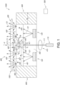
- the first light generating device 110 is configured to provide first device light 111 (in the light mixing chamber 500).
- the first light generating device 110 comprises one or more of a laser and a superluminescent diode.
- Reference 415 refers to optics, which may be used to provide a substantial part of the first device light to the first luminescent material 210. Hence, a substantial part of the first device light 211 may be received by the first luminescent material 210 without intermediate reflections.
- the first window element part 410 may be configured to transmit less than 1% of the first device light 111 reaching the first window element part 410.
- the first light generating device 110 and first luminescent material 210 may be configured to generate white light emanating from a downstream side 416 of the first window element part 410.
- the white light may comprise the first luminescent material light 211.
- the second window element part 420 may be configured to transmit at least 30% of the second device light 121 under perpendicular radiation of the second device light 121 and/or (ii) is (according to the invention) configured to reflect at least 30% of the second device light 121 under perpendicular radiation of the second device light 121.
- the first window element part 410 and the second window element part 420 are at least partly (optically) separated by a reflective element 430.
- the reflective element 430 may have a thickness (d1) of at maximum 1 ⁇ m. In embodiments, the reflective element 430 may have a higher thermal conductivity than the first window element part 410 and/or the second window element part 420.
- the reflective element 430 is an embodiments of an optical separation element.
- the first window element part 410 may have a first height h1 and the second window element part 420 has a second height h2. In specific embodiments, h1 ⁇ h2.
- the second window element part 420 may define a second window element cavity 440 configured at a downstream side 416 of the first window element part 410.
- Reference h3 indicates the height or depth of the second window element cavity 440.
- the second window element cavity 440 may be configured as reflector cavity. Especially, at a light entrance side 441 of the second window element cavity 440 at least part of the first window element part 410 may be configured. As schematically depicted, the light entrance side of the second window element cavity may in embodiments essentially coincide with the downstream face 412 of the first window element 410.
- the first window element part 410 may have a first cross-sectional area A1.
- the second window element part 420 may have a second cross-sectional area A2. Especially, 0.001 ⁇ A1/A2 ⁇ 0.1.
- the light generating system 1000 may further comprising a thermally conductive element 600 (having a higher thermal conductivity than the first window element part 410 and/or the second window element part 420).
- the light mixing chamber 500 may be partly defined by the thermally conductive element 600.
- the thermally conductive element 600 may comprise or may be thermally coupled to one or more of a heat sink, a heat pipe, and a heat spreader.
- the light generating system 1000 may be provided a light package, with all elements integrated in a single device or module.
- the light generating system 1000 may further comprise a control system 300.
- the control system 300 may be configured to control a beam shape of system light 1001 emanating from the light generating system by controlling the first light generating device 110 and the second light generating device 120.
- the invention also provides a method for controlling a beam shape of a beam of system light 1001, the method comprising controlling the first light generating device 110 and the second light generating device 120 of the light generating system 1000.
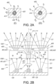
- Fig. 2a schematically depict some top views of the window element 400 including the first window element part 410, the second window element part 420, and the optional intermediate reflective element 430, which may be used to optically separate the first window element part 410 and the second window element part 420.
- the respective cross-sectional areas A1 and A2 are indicated.
- the total cross-sectional area of the window element 400 may be defined as A3.
- Fig. 2b schematically depicts that the beam width, indicated with beam angles ⁇ 1 for a beam of first luminescent material light 211, and ⁇ 2 for a beam of second device light may be different, especially the former smaller than the latter.
- the beam angles may be defined by the full width half maxima.
- the light from the first window element may be collimated to ⁇ 6° FWHM, preferably ⁇ 5°, more preferably ⁇ 4°, most preferably ⁇ 3° FWHM (full width half maximum).
- ⁇ 1 may be at maximum 6°.
- the light from the second window element may be collimated to ⁇ 7° FWHM, such as especially ⁇ 10°, more preferably ⁇ 15°, most preferably ⁇ 20 such as for example 25° FWHM.
- ⁇ 2 may be at minimum 6°.
- Collimation may e.g. be achieved with a lens or other optical element, indicated with reference 450.
- Optics 450 may be used to provide relative narrow beams.
- the optics may in embodiments comprise collimating optics, such as lenses, reflectors, collimators, compound parabolic concentrator type optical elements. As indicated above, in specific embodiments, a single optical element is configured downstream of both the first window element and second window element.
- References 421 and 422 indicate an upstream face and a downstream face, respectively, of the second window element part 420. A distance between those faces 421,422 may be indicate with reference h2. In embodiments, over at least 50%, such as at least 70% of the cross-sectional area A2 of the second window element part 420, the upstream face 421 and the downstream face 422 may be configured parallel.
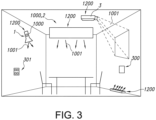
- Fig. 3 schematically depicts an embodiment of a luminaire 2 comprising the light generating system 1000 as described above.
- Reference 301 indicates a user interface which may be functionally coupled with the control system 300 comprised by or functionally coupled to the light generating system 1000.
- Fig. 3 also schematically depicts an embodiment of lamp 1 comprising the light generating system 1000.
- Reference 3 indicates a projector device or projector system, which may be used to project images, such as at a wall, which may also comprise the light generating system 1000.
- Fig. 3 schematically depicts embodiments of a lighting device 1200 selected from the group of a lamp 1, a luminaire 2, a projector device 3, a disinfection device, and an optical wireless communication device, comprising the light generating system 1000 as described herein.
- such lighting device may be a lamp 1, a luminaire 2, a projector device 3, a disinfection device, or an optical wireless communication device.
- Lighting device light escaping from the lighting device 1200 is indicated with reference 1201.
- Lighting device light 1201 may essentially consist of system light 1001, and may in specific embodiments thus be system light 1001.
- the terms “substantially” or “essentially” herein, and similar terms, will be understood by the person skilled in the art.
- the terms “substantially” or “essentially” may also include embodiments with “entirely”, “completely”, “all”, etc. Hence, in embodiments the adjective substantially or essentially may also be removed.
- the term “substantially” or the term “essentially” may also relate to 90% or higher, such as 95% or higher, especially 99% or higher, even more especially 99.5% or higher, including 100%.
- the invention may be implemented by means of hardware comprising several distinct elements, and by means of a suitably programmed computer.
- a device claim, or an apparatus claim, or a system claim enumerating several means, several of these means may be embodied by one and the same item of hardware.
- the mere fact that certain measures are recited in mutually different dependent claims does not indicate that a combination of these measures cannot be used to advantage.
- the invention (thus) provides a software product, which, when running on a computer is capable of bringing about (one or more embodiments of) the method as described herein.
- the invention also provides a control system that may control the device, apparatus, or system, or that may execute the herein described method or process. Yet further, the invention also provides a computer program product, when running on a computer which is functionally coupled to or comprised by the device, apparatus, or system, controls one or more controllable elements of such device, apparatus, or system.
- the invention further applies to a device, apparatus, or system comprising one or more of the characterizing features described in the description and/or shown in the attached drawings.
- the invention further pertains to a method or process comprising one or more of the characterizing features described in the description and/or shown in the attached drawings.
Landscapes
- Engineering & Computer Science (AREA)
- General Engineering & Computer Science (AREA)
- Physics & Mathematics (AREA)
- Microelectronics & Electronic Packaging (AREA)
- Optics & Photonics (AREA)
- Spectroscopy & Molecular Physics (AREA)
- Semiconductor Lasers (AREA)
- Luminescent Compositions (AREA)
Claims (15)
- Lichterzeugungssystem (1000), umfassend eine erste Lichterzeugungsvorrichtung (110), eine zweite Lichterzeugungsvorrichtung (120), einen ersten Leuchtstoff (210), ein Fensterelement (400) und eine Lichtmischkammer (500), wobei:- die erste Lichterzeugungsvorrichtung (110) konfiguriert ist, um ein Licht (111) der ersten Vorrichtung bereitzustellen; wobei die erste Lichterzeugungsvorrichtung (110) eines oder mehrere von einem Laser und einer Superlumineszenzdiode umfasst;- die zweite Lichterzeugungsvorrichtung (120) konfiguriert ist, um ein Licht (121) einer zweiten Vorrichtung zu erzeugen; wobei die zweite Lichterzeugungsvorrichtung (120) eine Festkörperlichtquelle umfasst;- die Lichtmischkammer (500) durch das Fensterelement (400) und reflektierende Wände definiert ist, wobei die reflektierenden Wände eine durchschnittliche Reflektivität für das zweite Vorrichtungslicht von mindestens 50 % aufweisen;- das Fensterelement (400) umfasst: (i) einen ersten Fensterelementteil (410), umfassend den ersten Leuchtstoff (210), wobei der erste Fensterelementteil (410) in einer lichtempfangenden Beziehung mit der ersten Lichterzeugungsvorrichtung (110) konfiguriert ist, und (ii) einen zweiten Fensterelementteil (420), wobei der zweite Fensterelementteil (420) für das Licht (121) der zweiten Vorrichtung lichtdurchlässig ist, und wobei der zweite Fensterelementteil (420) in einer lichtempfangenden Beziehung mit der zweiten Lichterzeugungsvorrichtung (120) konfiguriert ist; wobei der erste Fensterelementteil (410) und der zweite Fensterelementteil (420) in thermischem Kontakt miteinander konfiguriert sind; wobei der erste Fensterelementteil (410) und der zweite Fensterelementteil (420) sich in der Materialzusammensetzung unterscheiden;- der erste Leuchtstoff (210) konfiguriert ist, um mindestens einen Teil des Lichts (111) der ersten Vorrichtung in Licht (211) des ersten Leuchtstoffs umzuwandeln;- die Reflektivität des zweiten Fensterteils (420) aus dem Bereich von 30 - 70 % für das Licht (121) der zweiten Vorrichtung ausgewählt ist; und- wobei der zweite Fensterelementteil (420) keinen Leuchtstoff umfasst, der konfiguriert ist, um das Licht (121) der zweiten Vorrichtung umzuwandeln.
- Lichterzeugungssystem (1000) nach Anspruch 1, wobei die zweite Lichterzeugungsvorrichtung (120) eine oder mehrere LEDs umfasst.
- Lichterzeugungssystem (1000) nach einem der vorstehenden Ansprüche, wobei der erste Fensterelementteil (410) konfiguriert ist, um einen Teil des Lichts (111) der ersten Vorrichtung zu übermitteln, wobei in einem Betriebsmodus des Lichterzeugungssystems (1000) die erste Lichterzeugungsvorrichtung (110) und der erste Leuchtstoff (210) konfiguriert sind, um weißes Licht zu erzeugen, das von einer nachgelagerten Seite (416) des ersten Fensterelementteils (410) ausgeht, wobei das weiße Licht Licht des ersten Leuchtstoffs (211) und übermitteltes Licht (111) der ersten Vorrichtung umfasst.
- Lichterzeugungssystem (1000) nach Anspruch 3, wobei die erste Lichterzeugungsvorrichtung (110) konfiguriert ist, um blaues Licht (111) der ersten Vorrichtung zu erzeugen, und wobei der erste Leuchtstoff (210) konfiguriert ist, um mindestens einen Teil des Licht (111) der ersten Vorrichtung in Licht (211) des ersten Leuchtstoffs umzuwandeln, das eine Intensität bei einer oder mehreren Wellenlängen aufweist, die aus dem Wellenlängenbereich von 530-750 nm ausgewählt sind.
- Lichterzeugungssystem (1000) nach einem der vorstehenden Ansprüche, wobei mindestens 70 % des Lichts (121) der zweiten Vorrichtung, das aus dem Fensterelement (400) austritt, über das zweite Fensterelement (420) austritt.
- Lichterzeugungssystem (1000) nach einem der vorstehenden Ansprüche, wobei der erste Fensterelementteil (410) einen Keramikkörper umfasst und wobei der zweite Fensterelementteil (420) einen Keramikkörper umfasst.
- Lichterzeugungssystem (1000) nach einem der vorstehenden Ansprüche, wobei der erste Fensterelementteil (410) und der zweite Fensterelementteil (420) mindestens teilweise durch ein reflektierendes Element (430) getrennt sind.
- Lichterzeugungssystem (1000) nach Anspruch 7, wobei das reflektierende Element (430) eine höhere Wärmeleitfähigkeit als der erste Fensterelementteil (410) und/oder der zweite Fensterelementteil (420) aufweist.
- Lichterzeugungssystem (1000) nach einem der vorstehenden Ansprüche, wobei der erste Fensterelementteil (410) eine erste Höhe (h1) aufweist und wobei der zweite Fensterelementteil (420) eine zweite Höhe (h2) aufweist, wobei h1<h2, und wobei der zweite Fensterelementteil (420) einen zweiten Fensterelementhohlraum (440) definiert, der an einer nachgelagerten Seite (416) des ersten Fensterelementteils (410) konfiguriert ist.
- Lichterzeugungssystem (1000) nach Anspruch 9, wobei der zweite Fensterelementhohlraum (440) als Reflektorhohlraum ausgebildet ist, wobei an einer Lichteintrittsseite (441) des zweiten Fensterelementhohlraums (440) mindestens ein Teil des ersten Fensterelementteils (410) konfiguriert ist.
- Lichterzeugungssystem (1000) nach einem der vorstehenden Ansprüche, wobei der erste Fensterelementteil (410) eine erste Querschnittsfläche A1 aufweist, wobei der zweite Fensterelementteil (420) eine zweite Querschnittsfläche A2 aufweist, wobei 0,001≤A1/A2≤0,1.
- Lichterzeugungssystem (1000) nach einem der vorstehenden Ansprüche, ferner umfassend ein wärmeleitfähiges Element (600), wobei die Lichtmischkammer (500) teilweise durch das wärmeleitfähige Element (600) definiert ist, wobei das wärmeleitfähige Element (600) eines oder mehrere von einer Wärmsenke, einem Wärmerohr und einem Wärmeverteiler umfasst oder mit einem oder mehreren davon thermisch gekoppelt ist.
- Lichterzeugungssystem (1000) nach einem der vorstehenden Ansprüche, ferner umfassend ein Steuersystem (300), das konfiguriert ist, um eine Strahlform von Systemlicht (1001), das von der Lichterzeugungsvorrichtung ausgeht, durch Steuern der ersten Lichterzeugungsvorrichtung (110) und der zweiten Lichterzeugungsvorrichtung (120) zu steuern.
- Verfahren zum Steuern einer Strahlform eines Strahls von Systemlicht (1001), wobei das Verfahren das Steuern der ersten Lichterzeugungsvorrichtung (110) und der zweiten Lichterzeugungsvorrichtung (120) des Lichterzeugungssystems (1000) nach einem der vorstehenden Ansprüche umfasst.
- Beleuchtungsvorrichtung (1200), die aus der Gruppe von einer Lampe (1), einer Leuchte (2), einer Projektorvorrichtung (3), einer Desinfektionsvorrichtung und einer optischen drahtlosen Kommunikationsvorrichtung ausgewählt ist, umfassend das Lichterzeugungssystem (1000) nach einem der Ansprüche 1 bis 13.
Applications Claiming Priority (2)
| Application Number | Priority Date | Filing Date | Title |
|---|---|---|---|
| EP21183068 | 2021-07-01 | ||
| PCT/EP2022/066732 WO2023274770A1 (en) | 2021-07-01 | 2022-06-20 | Integrated solid state light source and phosphor module |
Publications (2)
| Publication Number | Publication Date |
|---|---|
| EP4363771A1 EP4363771A1 (de) | 2024-05-08 |
| EP4363771B1 true EP4363771B1 (de) | 2025-03-26 |
Family
ID=76744660
Family Applications (1)
| Application Number | Title | Priority Date | Filing Date |
|---|---|---|---|
| EP22737798.3A Active EP4363771B1 (de) | 2021-07-01 | 2022-06-20 | Integrierte festkörperlichtquelle und leuchtstoffmodul |
Country Status (5)
| Country | Link |
|---|---|
| US (1) | US12264790B2 (de) |
| EP (1) | EP4363771B1 (de) |
| JP (1) | JP7604685B2 (de) |
| CN (1) | CN117597545A (de) |
| WO (1) | WO2023274770A1 (de) |
Family Cites Families (10)
| Publication number | Priority date | Publication date | Assignee | Title |
|---|---|---|---|---|
| US7915627B2 (en) * | 2007-10-17 | 2011-03-29 | Intematix Corporation | Light emitting device with phosphor wavelength conversion |
| RU2508616C2 (ru) * | 2008-02-27 | 2014-02-27 | Конинклейке Филипс Электроникс Н.В. | Осветительное устройство с сид и одним или более пропускающими окнами |
| US20130093362A1 (en) * | 2011-10-13 | 2013-04-18 | Intematix Corporation | Methods and apparatus for implementing tunable light emitting device with remote wavelength conversion |
| RU2648080C1 (ru) | 2014-09-11 | 2018-03-22 | Филипс Лайтинг Холдинг Б.В. | Сид-модуль с преобразованием люминофором с улучшенными передачей белого цвета и эффективностью преобразования |
| DE102015224692A1 (de) | 2015-12-09 | 2017-06-14 | Osram Gmbh | Lichterzeugung mit leuchtdiode und laser |
| DE102016201606A1 (de) * | 2016-02-03 | 2017-08-03 | Osram Gmbh | Beleuchtungsvorrichtung zur emission von beleuchtungslicht |
| KR20170142760A (ko) * | 2016-06-20 | 2017-12-28 | 엘지전자 주식회사 | 조명장치 |
| DE102018211342A1 (de) * | 2018-07-10 | 2020-01-16 | Osram Gmbh | Optische vorrichtung mit einer halterung, eine anordnung und ein scheinwerfer |
| GB2579801B (en) | 2018-12-13 | 2021-04-14 | Exalos Ag | Superluminescent diode module |
| WO2020257091A1 (en) | 2019-06-17 | 2020-12-24 | Optonomous Technologies, Inc. | Hybrid led/laser light source for smart headlight applications |
-
2022
- 2022-06-20 CN CN202280046197.5A patent/CN117597545A/zh active Pending
- 2022-06-20 WO PCT/EP2022/066732 patent/WO2023274770A1/en not_active Ceased
- 2022-06-20 JP JP2023580475A patent/JP7604685B2/ja active Active
- 2022-06-20 EP EP22737798.3A patent/EP4363771B1/de active Active
- 2022-06-20 US US18/575,983 patent/US12264790B2/en active Active
Also Published As
| Publication number | Publication date |
|---|---|
| EP4363771A1 (de) | 2024-05-08 |
| WO2023274770A1 (en) | 2023-01-05 |
| JP7604685B2 (ja) | 2024-12-23 |
| CN117597545A (zh) | 2024-02-23 |
| US12264790B2 (en) | 2025-04-01 |
| JP2024524377A (ja) | 2024-07-05 |
| US20250020289A1 (en) | 2025-01-16 |
Similar Documents
| Publication | Publication Date | Title |
|---|---|---|
| TW200929621A (en) | Light emitting device with phosphor wavelength conversion | |
| EP4649259A1 (de) | Laserphosphorbasierte bühnenbeleuchtungsmaschine mit einer hocheffizienten polarisationserhaltenden diffusorkonfiguration | |
| EP4409196B1 (de) | Abstimmbares laserquellen-weisslichtmodul | |
| US12398860B2 (en) | High intensity white light source with good uniformity based on a plurality of light sources | |
| US20240421554A1 (en) | White light source | |
| US12287087B2 (en) | High brightness light source comprising a blue laser pumping a green yellow phosphor and a yellow orange superluminescent diode pumping a red phosphor | |
| US12332416B2 (en) | Laser SMD package with phosphor and light incoupler | |
| US12264790B2 (en) | Integrated solid state light source and phosphor module | |
| WO2022258591A1 (en) | White light source without red solid state light source | |
| EP4476477B1 (de) | Kühlkörper mit einem geschlossenen schlitz zum pumpen eines zylindrischen phosphorkörpers | |
| US20260086272A1 (en) | Annular shaped phosphor in combination with axicon lens for producing laser pumped high intensity white light source | |
| US12416386B2 (en) | High brightness light source | |
| WO2023247568A1 (en) | Laser source lightguide spider module |
Legal Events
| Date | Code | Title | Description |
|---|---|---|---|
| STAA | Information on the status of an ep patent application or granted ep patent |
Free format text: STATUS: UNKNOWN |
|
| STAA | Information on the status of an ep patent application or granted ep patent |
Free format text: STATUS: THE INTERNATIONAL PUBLICATION HAS BEEN MADE |
|
| PUAI | Public reference made under article 153(3) epc to a published international application that has entered the european phase |
Free format text: ORIGINAL CODE: 0009012 |
|
| STAA | Information on the status of an ep patent application or granted ep patent |
Free format text: STATUS: REQUEST FOR EXAMINATION WAS MADE |
|
| 17P | Request for examination filed |
Effective date: 20240201 |
|
| AK | Designated contracting states |
Kind code of ref document: A1 Designated state(s): AL AT BE BG CH CY CZ DE DK EE ES FI FR GB GR HR HU IE IS IT LI LT LU LV MC MK MT NL NO PL PT RO RS SE SI SK SM TR |
|
| DAV | Request for validation of the european patent (deleted) | ||
| DAX | Request for extension of the european patent (deleted) | ||
| GRAP | Despatch of communication of intention to grant a patent |
Free format text: ORIGINAL CODE: EPIDOSNIGR1 |
|
| STAA | Information on the status of an ep patent application or granted ep patent |
Free format text: STATUS: GRANT OF PATENT IS INTENDED |
|
| INTG | Intention to grant announced |
Effective date: 20241017 |
|
| GRAS | Grant fee paid |
Free format text: ORIGINAL CODE: EPIDOSNIGR3 |
|
| GRAA | (expected) grant |
Free format text: ORIGINAL CODE: 0009210 |
|
| STAA | Information on the status of an ep patent application or granted ep patent |
Free format text: STATUS: THE PATENT HAS BEEN GRANTED |
|
| AK | Designated contracting states |
Kind code of ref document: B1 Designated state(s): AL AT BE BG CH CY CZ DE DK EE ES FI FR GB GR HR HU IE IS IT LI LT LU LV MC MK MT NL NO PL PT RO RS SE SI SK SM TR |
|
| P01 | Opt-out of the competence of the unified patent court (upc) registered |
Free format text: CASE NUMBER: APP_7471/2025 Effective date: 20250213 |
|
| REG | Reference to a national code |
Ref country code: GB Ref legal event code: FG4D |
|
| REG | Reference to a national code |
Ref country code: CH Ref legal event code: EP |
|
| REG | Reference to a national code |
Ref country code: DE Ref legal event code: R096 Ref document number: 602022012322 Country of ref document: DE |
|
| REG | Reference to a national code |
Ref country code: IE Ref legal event code: FG4D |
|
| PG25 | Lapsed in a contracting state [announced via postgrant information from national office to epo] |
Ref country code: RS Free format text: LAPSE BECAUSE OF FAILURE TO SUBMIT A TRANSLATION OF THE DESCRIPTION OR TO PAY THE FEE WITHIN THE PRESCRIBED TIME-LIMIT Effective date: 20250626 |
|
| PG25 | Lapsed in a contracting state [announced via postgrant information from national office to epo] |
Ref country code: FI Free format text: LAPSE BECAUSE OF FAILURE TO SUBMIT A TRANSLATION OF THE DESCRIPTION OR TO PAY THE FEE WITHIN THE PRESCRIBED TIME-LIMIT Effective date: 20250326 |
|
| REG | Reference to a national code |
Ref country code: LT Ref legal event code: MG9D |
|
| PG25 | Lapsed in a contracting state [announced via postgrant information from national office to epo] |
Ref country code: NO Free format text: LAPSE BECAUSE OF FAILURE TO SUBMIT A TRANSLATION OF THE DESCRIPTION OR TO PAY THE FEE WITHIN THE PRESCRIBED TIME-LIMIT Effective date: 20250626 |
|
| PG25 | Lapsed in a contracting state [announced via postgrant information from national office to epo] |
Ref country code: HR Free format text: LAPSE BECAUSE OF FAILURE TO SUBMIT A TRANSLATION OF THE DESCRIPTION OR TO PAY THE FEE WITHIN THE PRESCRIBED TIME-LIMIT Effective date: 20250326 |
|
| PG25 | Lapsed in a contracting state [announced via postgrant information from national office to epo] |
Ref country code: LV Free format text: LAPSE BECAUSE OF FAILURE TO SUBMIT A TRANSLATION OF THE DESCRIPTION OR TO PAY THE FEE WITHIN THE PRESCRIBED TIME-LIMIT Effective date: 20250326 |
|
| PGFP | Annual fee paid to national office [announced via postgrant information from national office to epo] |
Ref country code: FR Payment date: 20250624 Year of fee payment: 4 |
|
| PG25 | Lapsed in a contracting state [announced via postgrant information from national office to epo] |
Ref country code: GR Free format text: LAPSE BECAUSE OF FAILURE TO SUBMIT A TRANSLATION OF THE DESCRIPTION OR TO PAY THE FEE WITHIN THE PRESCRIBED TIME-LIMIT Effective date: 20250627 Ref country code: BG Free format text: LAPSE BECAUSE OF FAILURE TO SUBMIT A TRANSLATION OF THE DESCRIPTION OR TO PAY THE FEE WITHIN THE PRESCRIBED TIME-LIMIT Effective date: 20250326 |
|
| PGFP | Annual fee paid to national office [announced via postgrant information from national office to epo] |
Ref country code: AT Payment date: 20250721 Year of fee payment: 4 |
|
| REG | Reference to a national code |
Ref country code: NL Ref legal event code: MP Effective date: 20250326 |
|
| PG25 | Lapsed in a contracting state [announced via postgrant information from national office to epo] |
Ref country code: NL Free format text: LAPSE BECAUSE OF FAILURE TO SUBMIT A TRANSLATION OF THE DESCRIPTION OR TO PAY THE FEE WITHIN THE PRESCRIBED TIME-LIMIT Effective date: 20250326 |
|
| PG25 | Lapsed in a contracting state [announced via postgrant information from national office to epo] |
Ref country code: SE Free format text: LAPSE BECAUSE OF FAILURE TO SUBMIT A TRANSLATION OF THE DESCRIPTION OR TO PAY THE FEE WITHIN THE PRESCRIBED TIME-LIMIT Effective date: 20250326 |
|
| REG | Reference to a national code |
Ref country code: AT Ref legal event code: MK05 Ref document number: 1779288 Country of ref document: AT Kind code of ref document: T Effective date: 20250326 |
|
| PG25 | Lapsed in a contracting state [announced via postgrant information from national office to epo] |
Ref country code: SM Free format text: LAPSE BECAUSE OF FAILURE TO SUBMIT A TRANSLATION OF THE DESCRIPTION OR TO PAY THE FEE WITHIN THE PRESCRIBED TIME-LIMIT Effective date: 20250326 |
|
| PG25 | Lapsed in a contracting state [announced via postgrant information from national office to epo] |
Ref country code: PT Free format text: LAPSE BECAUSE OF FAILURE TO SUBMIT A TRANSLATION OF THE DESCRIPTION OR TO PAY THE FEE WITHIN THE PRESCRIBED TIME-LIMIT Effective date: 20250728 Ref country code: ES Free format text: LAPSE BECAUSE OF FAILURE TO SUBMIT A TRANSLATION OF THE DESCRIPTION OR TO PAY THE FEE WITHIN THE PRESCRIBED TIME-LIMIT Effective date: 20250326 |
|
| PGFP | Annual fee paid to national office [announced via postgrant information from national office to epo] |
Ref country code: DE Payment date: 20250827 Year of fee payment: 4 |
|
| PG25 | Lapsed in a contracting state [announced via postgrant information from national office to epo] |
Ref country code: IT Free format text: LAPSE BECAUSE OF FAILURE TO SUBMIT A TRANSLATION OF THE DESCRIPTION OR TO PAY THE FEE WITHIN THE PRESCRIBED TIME-LIMIT Effective date: 20250326 Ref country code: PL Free format text: LAPSE BECAUSE OF FAILURE TO SUBMIT A TRANSLATION OF THE DESCRIPTION OR TO PAY THE FEE WITHIN THE PRESCRIBED TIME-LIMIT Effective date: 20250326 |
|
| PG25 | Lapsed in a contracting state [announced via postgrant information from national office to epo] |
Ref country code: AT Free format text: LAPSE BECAUSE OF FAILURE TO SUBMIT A TRANSLATION OF THE DESCRIPTION OR TO PAY THE FEE WITHIN THE PRESCRIBED TIME-LIMIT Effective date: 20250326 |
|
| PG25 | Lapsed in a contracting state [announced via postgrant information from national office to epo] |
Ref country code: EE Free format text: LAPSE BECAUSE OF FAILURE TO SUBMIT A TRANSLATION OF THE DESCRIPTION OR TO PAY THE FEE WITHIN THE PRESCRIBED TIME-LIMIT Effective date: 20250326 |
|
| PG25 | Lapsed in a contracting state [announced via postgrant information from national office to epo] |
Ref country code: RO Free format text: LAPSE BECAUSE OF FAILURE TO SUBMIT A TRANSLATION OF THE DESCRIPTION OR TO PAY THE FEE WITHIN THE PRESCRIBED TIME-LIMIT Effective date: 20250326 |
|
| PG25 | Lapsed in a contracting state [announced via postgrant information from national office to epo] |
Ref country code: SK Free format text: LAPSE BECAUSE OF FAILURE TO SUBMIT A TRANSLATION OF THE DESCRIPTION OR TO PAY THE FEE WITHIN THE PRESCRIBED TIME-LIMIT Effective date: 20250326 |
|
| PG25 | Lapsed in a contracting state [announced via postgrant information from national office to epo] |
Ref country code: IS Free format text: LAPSE BECAUSE OF FAILURE TO SUBMIT A TRANSLATION OF THE DESCRIPTION OR TO PAY THE FEE WITHIN THE PRESCRIBED TIME-LIMIT Effective date: 20250726 |
|
| REG | Reference to a national code |
Ref country code: DE Ref legal event code: R097 Ref document number: 602022012322 Country of ref document: DE |
|
| PG25 | Lapsed in a contracting state [announced via postgrant information from national office to epo] |
Ref country code: DK Free format text: LAPSE BECAUSE OF FAILURE TO SUBMIT A TRANSLATION OF THE DESCRIPTION OR TO PAY THE FEE WITHIN THE PRESCRIBED TIME-LIMIT Effective date: 20250326 |
|
| PG25 | Lapsed in a contracting state [announced via postgrant information from national office to epo] |
Ref country code: CZ Free format text: LAPSE BECAUSE OF FAILURE TO SUBMIT A TRANSLATION OF THE DESCRIPTION OR TO PAY THE FEE WITHIN THE PRESCRIBED TIME-LIMIT Effective date: 20250326 |
|
| REG | Reference to a national code |
Ref country code: CH Ref legal event code: H13 Free format text: ST27 STATUS EVENT CODE: U-0-0-H10-H13 (AS PROVIDED BY THE NATIONAL OFFICE) Effective date: 20260127 |
|
| PG25 | Lapsed in a contracting state [announced via postgrant information from national office to epo] |
Ref country code: MC Free format text: LAPSE BECAUSE OF FAILURE TO SUBMIT A TRANSLATION OF THE DESCRIPTION OR TO PAY THE FEE WITHIN THE PRESCRIBED TIME-LIMIT Effective date: 20250326 |
|
| PLBE | No opposition filed within time limit |
Free format text: ORIGINAL CODE: 0009261 |
|
| STAA | Information on the status of an ep patent application or granted ep patent |
Free format text: STATUS: NO OPPOSITION FILED WITHIN TIME LIMIT |
|
| REG | Reference to a national code |
Ref country code: CH Ref legal event code: L10 Free format text: ST27 STATUS EVENT CODE: U-0-0-L10-L00 (AS PROVIDED BY THE NATIONAL OFFICE) Effective date: 20260211 |
|
| PG25 | Lapsed in a contracting state [announced via postgrant information from national office to epo] |
Ref country code: LU Free format text: LAPSE BECAUSE OF NON-PAYMENT OF DUE FEES Effective date: 20250620 |
|
| REG | Reference to a national code |
Ref country code: BE Ref legal event code: MM Effective date: 20250630 |
|
| 26N | No opposition filed |
Effective date: 20260105 |
|
| PG25 | Lapsed in a contracting state [announced via postgrant information from national office to epo] |
Ref country code: IE Free format text: LAPSE BECAUSE OF NON-PAYMENT OF DUE FEES Effective date: 20250620 |
|
| PG25 | Lapsed in a contracting state [announced via postgrant information from national office to epo] |
Ref country code: BE Free format text: LAPSE BECAUSE OF NON-PAYMENT OF DUE FEES Effective date: 20250630 |
|
| PG25 | Lapsed in a contracting state [announced via postgrant information from national office to epo] |
Ref country code: CH Free format text: LAPSE BECAUSE OF NON-PAYMENT OF DUE FEES Effective date: 20250630 |