EP4362442A1 - Wireless relay device, first terminal device, second terminal device, communication system - Google Patents
Wireless relay device, first terminal device, second terminal device, communication system Download PDFInfo
- Publication number
- EP4362442A1 EP4362442A1 EP22827947.7A EP22827947A EP4362442A1 EP 4362442 A1 EP4362442 A1 EP 4362442A1 EP 22827947 A EP22827947 A EP 22827947A EP 4362442 A1 EP4362442 A1 EP 4362442A1
- Authority
- EP
- European Patent Office
- Prior art keywords
- sound signal
- terminal apparatus
- identifier
- unit
- wireless relay
- Prior art date
- Legal status (The legal status is an assumption and is not a legal conclusion. Google has not performed a legal analysis and makes no representation as to the accuracy of the status listed.)
- Granted
Links
Images






Classifications
-
- H—ELECTRICITY
- H04—ELECTRIC COMMUNICATION TECHNIQUE
- H04M—TELEPHONIC COMMUNICATION
- H04M3/00—Automatic or semi-automatic exchanges
- H04M3/42—Systems providing special services or facilities to subscribers
- H04M3/56—Arrangements for connecting several subscribers to a common circuit, i.e. affording conference facilities
- H04M3/563—User guidance or feature selection
- H04M3/566—User guidance or feature selection relating to a participants right to speak
-
- H—ELECTRICITY
- H04—ELECTRIC COMMUNICATION TECHNIQUE
- H04B—TRANSMISSION
- H04B7/00—Radio transmission systems, i.e. using radiation field
- H04B7/14—Relay systems
- H04B7/15—Active relay systems
- H04B7/155—Ground-based stations
-
- H—ELECTRICITY
- H04—ELECTRIC COMMUNICATION TECHNIQUE
- H04M—TELEPHONIC COMMUNICATION
- H04M3/00—Automatic or semi-automatic exchanges
- H04M3/42—Systems providing special services or facilities to subscribers
- H04M3/42025—Calling or Called party identification service
- H04M3/42034—Calling party identification service
- H04M3/42059—Making use of the calling party identifier
-
- H—ELECTRICITY
- H04—ELECTRIC COMMUNICATION TECHNIQUE
- H04W—WIRELESS COMMUNICATION NETWORKS
- H04W4/00—Services specially adapted for wireless communication networks; Facilities therefor
- H04W4/06—Selective distribution of broadcast services, e.g. multimedia broadcast multicast service [MBMS]; Services to user groups; One-way selective calling services
- H04W4/10—Push-to-Talk [PTT] or Push-On-Call services
-
- H—ELECTRICITY
- H04—ELECTRIC COMMUNICATION TECHNIQUE
- H04W—WIRELESS COMMUNICATION NETWORKS
- H04W88/00—Devices specially adapted for wireless communication networks, e.g. terminals, base stations or access point devices
- H04W88/02—Terminal devices
- H04W88/04—Terminal devices adapted for relaying to or from another terminal or user
Definitions
- the present invention relates to communication technology and, more particularly, to a wireless relay apparatus, a first terminal apparatus, a second terminal apparatus, and a communication system that performs communication of sound signals.
- an answering machine system for terminal apparatuses is provided.
- the control station on the network side checks for connection of a terminal apparatus and notifies the terminal apparatus that there is a message when the terminal apparatus is connected (for example, PATENT LITERATURE 1).
- patent literature 1 assumes individual calls, the control station can confirm whether the terminal apparatus is connected and can know from what point of time the terminal apparatus has not received a call. In a group call by simplex communication, however, it is difficult to confirm whether the terminal apparatus is connected.
- the present invention addresses the issue described above, and a purpose thereof is to provide a technology for reliably performing communication of information signals exemplified by sound.
- a wireless relay apparatus includes: a first communication unit that receives a first sound signal with an identifier attached thereto from a first terminal apparatus; a recording unit that records the first sound signal and the identifier received by the first communication unit; and a relay recording control unit that, when the second communication unit receives the identifier received last in time by the second terminal apparatus from the second terminal apparatus as a last identifier, causes the second communication unit to transmit a list of identifiers recorded in the recording unit after the last identifier to the second terminal apparatus, and that, when the second communication unit receives the identifier included in the list from the second terminal apparatus as a transmission request identifier, extracts the first sound signal corresponding to the transmission request identifier from the recording unit and causes the second communication unit to transmit the first sound signal extracted to the second terminal apparatus as the second sound signal.
- the communication system includes: a first terminal apparatus that transmits a first sound signal with an identifier attached thereto; a wireless relay apparatus that transmits the first sound signal as a second sound signal along with the identifier, when the first sound signal with the identifier attached thereto is received from the first terminal apparatus; and a second terminal apparatus that receives the second sound signal with the identifier attached thereto from the wireless relay apparatus.
- the wireless relay apparatus includes: a recording unit that records the first sound signal and the identifier received; a sound quality evaluation unit that evaluates a quality of the first sound signal received, that transmits the identifier to the first terminal apparatus as a retransmission request identifier, when an evaluation value is lower than a threshold value, and that replaces the first sound signal recorded in the recording unit with the first sound signal re-received, when the first sound signal with the retransmission request identifier attached thereto is re-received from the first terminal apparatus and when the evaluation value is equal to or higher than the threshold value: and a relay recording control unit that, when the identifier received last in time by the second terminal apparatus is received from the second terminal apparatus as a last identifier, transmits a list of identifiers recorded in the recording unit after the last identifier to the second terminal apparatus, and that, when the identifier included in the list is received from the second terminal apparatus as a transmission request identifier, extracts the first sound signal corresponding to the transmission
- the accuracy of communication of sound signals can be improved.
- the system can record a sound and automatically transmit the recorded sound when a call becomes enabled.
- the embodiment of the present invention relates to a simplex (unidirectional) communication system.
- a terminal apparatus on the transmitting side transmits a sound signal (hereinafter referred to as a "first sound signal") to a wireless relay apparatus, and the wireless relay apparatus transmits the received first sound signal to the terminal apparatus on the receiving side as a second audio signal.
- a group call is made, a plurality of terminal apparatuses on the receiving side are included.
- the terminal apparatus on the transmitting side does not detect whether the wireless relay apparatus was able to receive a signal normally from the terminal apparatus on the transmitting side. Therefore, the wireless relay apparatus is also required to be equipped with a technology that can reliably receive a signal from the terminal apparatus on the transmitting side and relay it to the terminal apparatus on the receiving side.
- the terminal apparatus on the transmitting side in this embodiment records the transmitted first sound signal, and the wireless relay apparatus records the received first sound signal. Furthermore, the first sound signal and the second sound signal are managed by identifiers (hereinafter referred to as a "call ID").
- the wireless relay apparatus reliably records the first sound signal reliably by requesting retransmission from the terminal apparatus on the transmitting side.
- the terminal apparatus on the receiving end moves from outside a communication service area into a communication service area and connects to the wireless relay apparatus, the terminal apparatus transmits the call ID of the second sound signal received last in time when it was previously located in the communication service area (hereinafter referred to as a "last call ID") to the wireless relay apparatus.
- the wireless relay apparatus acquires the last call ID from the terminal apparatus on the receiving side and transmits the unreceived first sound signal to the terminal apparatus on the receiving side as the second sound signal, using the first sound signal as recorded. Thereby, reliable transmission from the first terminal apparatus to the wireless relay apparatus and reliable transmission from the wireless relay apparatus to the second terminal apparatus are realized.
- FIG. 1 shows a configuration of a communication system 1000.
- the communication system 1000 includes a first terminal apparatus 100a to a third terminal apparatus 100c, which are generically referred to as a terminal apparatus 100, and a wireless relay apparatus 200.
- the number of terminal apparatuses 100 included in the communication system 1000 is not limited to "3", and the number of wireless relay apparatuses 200 is not limited to "1".
- simplex communication is performed in the communication system 1000.
- the terminal apparatus 100 is, for example, a wireless apparatus capable of performing sound communication by PTT (Push to Talk).
- PTT the terminal apparatus 100 can transmit a sound signal while the PTT button of the terminal apparatus 100 is being pressed down.
- the terminal apparatus 100 can receive a sound signal.
- the first terminal apparatus 100a corresponds to the terminal apparatus on the transmitting side described above
- the second terminal apparatus 100b and the third terminal apparatus 100c correspond to the terminal apparatus on the receiving side described above.
- the wireless relay apparatus 200 is a wireless device that relays communication between a plurality of terminal apparatuses 100.
- the transmission output of the wireless relay apparatus 200 is often set to be larger than the transmission output of the terminal apparatus 100.
- a first communication service area 10a is formed around the wireless relay apparatus 200, and a second communication service area 10b is formed around the first communication service area 10a.
- the first communication service area 10a is an area in which communication from the wireless relay apparatus 200 to the terminal apparatus 100 and communication from the terminal apparatus 100 to the wireless relay apparatus 200 are possible.
- the second communication service area 10b is an area in which communication from the wireless relay apparatus 200 to the terminal apparatus 100 is possible but communication from the terminal apparatus 100 to the wireless relay apparatus 200 is impossible.
- the boundary between the first communication service area 10a and the second communication service area 10b is not clear.
- the quality of communication from the terminal apparatus 100 to the wireless relay apparatus 200 gradually deteriorates as the terminal moves in a direction away from the first communication service area 10a.
- the first terminal apparatus 100a transmits the first sound signal with a call ID attached thereto when the PTT button is pressed down.
- the wireless relay apparatus 200 receives the first sound signal with the call ID attached thereto from the first terminal apparatus 100a
- the wireless relay apparatus 200 transmits the first sound signal as the second sound signal along with the call ID.
- the second terminal apparatus 100b and the third terminal apparatus 100c are located in the first communication service area 10a or the second communication service area 10b
- the second terminal apparatus 100b and the third terminal apparatus 100c receive the second sound signal with the call ID attached thereto from the wireless relay apparatus 200. In this way, a group call by the first terminal apparatus 100a, the second terminal apparatus 100b, and the third terminal apparatus 100c is performed.
- the second terminal apparatus 100b Since the second terminal apparatus 100b is moving from outside the second communication service area 10b toward the first communication service area 10a as shown in FIG. 1 , it is presumed that a miscall may occur in the second terminal apparatus 100b.
- the third terminal apparatus 100c stays in the first communication service area 10a as shown in FIG. 1 so that it is presumed that a miscall does not occur in the third terminal apparatus 100c. Therefore, only the second terminal apparatus 100b will be described hereinafter as the terminal apparatus on the receiving side.
- FIG. 2 is also used to describe the first process.
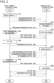
- FIG. 2 is a sequence chart showing a communication procedure performed by the first terminal apparatus 100a and the wireless relay apparatus 200.
- the PTT button is pressed down in the first terminal apparatus 100a (S10).
- the first terminal apparatus 100a transmits a transmission request to the wireless relay apparatus 200 to request channel assignment (S12).
- S12 represents a case where radio waves have not reached the wireless relay apparatus 200.
- the first terminal apparatus 100a transmits a transmission request again to the wireless relay apparatus 200 to request channel assignment (S14).
- the wireless relay apparatus 200 receives a transmission request, it checks that an unused channel is available (S16).
- the wireless relay apparatus 200 allocates the first terminal apparatus 100a to the unused channel and transmits a transmission permission notice to the first terminal apparatus 100a (S18).
- the first terminal apparatus 100a starts transmitting and recording the sound and data (S20), and the wireless relay apparatus 200 starts receiving and recording the sound and data (S22).
- the first terminal apparatus 100a transmits the first sound signal to the wireless relay apparatus 200 (S24, S26).
- the first terminal apparatus 100a records the first sound signal to be transmitted, and the wireless relay apparatus 200 records the received first sound signal.
- FIG. 3A to 3B show a data structure of a database stored in the wireless relay apparatus 200.
- FIG. 3A shows information on the first sound signal stored in the wireless relay apparatus 200.
- “Call ID” indicates the call ID
- “Receive Time” indicates the time of reception by the wireless relay apparatus 200
- “Source ID” indicates the ID of the transmission source terminal apparatus 100
- “Destination ID” indicates the ID of the destination terminal apparatus 100.
- “Destination ID” is the ID of the destination group.
- Quality measures include BER (Bit Error Rate), RSSI (Received Signal Strength Indicator), and Broken Block Number. Since known techniques may be used for these measurements, a description thereof is omitted here.
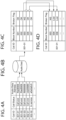
- FIGS. 4A to 4D show an overview of the process in the wireless relay apparatus 200.
- FIG. 4A shows information on the address of the first sound signal stored in the wireless relay apparatus 200. The address indicates a location where the first sound signal is stored in "Audio Data" of FIG. 4B .
- "Audio Data” is an area in which the first sound signal is stored in a recording unit 260.
- FIGS. 4C to 4D will be described later, and reference is made back to FIG. 3 .
- the PTT button is turned off in the first terminal apparatus 100a (S28).
- the first terminal apparatus 100a transmits a transmission end notice to the wireless relay apparatus 200 (S30).
- the wireless relay apparatus 200 checks the quality of the recorded first sound signal (S32).
- FIG. 4C shows a result of checking the quality of the first sound signal.
- the sound signal in a call indicated by "Call ID” is divided into a plurality of blocks and recorded accordingly.
- the blocks are managed by sequential block numbers indicated by "Block Number”.
- the quality of the sound signal is checked block by block.
- "OK” is set in "Broken Flag”
- "NG” is set in "Broken Flag”.
- "Lost” is set in "Broken Flag".
- the case where the quality of the first sound signal is deteriorated and the case where the first sound signal cannot be acquired represent cases where there is a problem with the quality of the first sound signal.
- FIG. 4D shows a result of extracting, from FIG. 4C , information on the block ID associated with a problem with the quality of the first sound signal.
- the block number 004 is not found in FIG. 4C , and so it is detected that the sound signal of the block of the first sound signal having the block number 004 could not be acquired. Reference is made back to FIG. 2 .
- the wireless relay apparatus 200 transmits a poor call status notice to the first terminal apparatus 100a (S34).
- the first terminal apparatus 100a receives the poor call status notice
- the first terminal apparatus 100a transmits a retransmission confirmation request to the wireless relay apparatus 200 (S36).
- the wireless relay apparatus 200 transmits a retransmission notice indicating the block of the first sound signal having a quality problem to the first terminal apparatus 100a (S38).
- the first terminal apparatus 100a constructs retransmission data so as to include the block indicated by the received retransmission notice (S40) and transmits the constructed retransmission data to the wireless relay apparatus 200 as the first sound signal (S42).
- the wireless relay apparatus 200 records the first sound signal (S44).
- the wireless relay apparatus 200 transmits "OK” or “NG” information to the first terminal apparatus 100a to indicate a result of the first sound signal (S46).
- the first terminal apparatus 100a transmits a transmission end notice to the wireless relay apparatus 200 (S48), and the wireless relay apparatus 200 transmits "OK" information responsive to the transmission end notice to the first terminal apparatus 100a.
- FIG. 5 is also used to describe the second process.
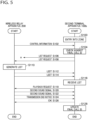
- FIG. 5 is a sequence chart showing a communication procedure performed by the wireless relay apparatus 200 and the second terminal apparatus 100b.
- the second terminal apparatus 100b moves from outside the second communication service area 10b toward the first communication service area 10a as shown in FIG. 1 and enters the zone of the second communication service area 10b (S100).
- the wireless relay apparatus 200 periodically transmits control information including the call ID of the second sound signal transmitted last in time (S102).
- FIG. 6 shows a data structure of another database stored in the wireless relay apparatus 200.
- the call ID of the second sound signal last transmitted in time from the wireless relay apparatus 200 is stored for each group.
- one group is the subject of description. Reference is made back to FIG. 5 .
- the second terminal apparatus 100b checks the call ID included in the control information with the last call ID (S104). When the call ID and the last call ID do not match, the second terminal apparatus 100b transmits a list request to the wireless relay apparatus 200 (S106). Since the second terminal apparatus 100b is located in the second communication service area 10b, the list request is not received by the wireless relay apparatus 200. When the second terminal apparatus 100b enters the first communication service area 10a, the list request from the second terminal apparatus 100b is received by the wireless relay apparatus 200 (S108). The wireless relay apparatus 200 generates a list (S110). The wireless relay apparatus 200 transmits the list to the second terminal apparatus 100b (S112, S114).
- the second terminal apparatus 100b receives the list (S116).
- the second terminal apparatus 100b transmits a playback request indicating the call ID, from amon the call IDs included in the list, for which playback is requested to the wireless relay apparatus 200 (S118).
- the wireless relay apparatus 200 transmits the second sound signal of the call ID indicated in the playback request to the second terminal apparatus 100b (S120, S122). After transmitting the second sound signal, the wireless relay apparatus 200 transmits a transmission end notice to the second terminal apparatus 100b (S124).
- the second terminal apparatus 100b transmits "OK" information responsive to the transmission end notice to the wireless relay apparatus 200 (S126).
- the second terminal apparatus 100b updates the last call ID (S128).
- the configuration of the first terminal apparatus 100a, the wireless relay apparatus 200, and the second terminal apparatus 100b in the communication system 1000 will be described in the order of (1) first process and (2) second process.
- FIG. 7 shows a configuration of the first terminal apparatus 100a.
- the first terminal apparatus 100a includes a communication unit 110, a user control unit 120, a microphone 130, a speaker 140, a processing unit 150, and a recording unit 160.
- the communication unit 110 includes a transmission unit 112 and a reception unit 114, and the processing unit 150 includes a retransmission control unit 152.
- the communication unit 110 performs simplex wireless communication. Therefore, the reception unit 114 does not receive a signal during a period when the transmission unit 112 is transmitting a signal, and the transmission unit 112 does not transmit a signal during a period when the reception unit 114 is receiving the signal. That is, one of the transmission unit 112 and the reception unit 114 operates and the other stops.
- the user control unit 120 is configured by a button, a touch panel, or the like, and receives an input from the user. It should be noted here that the button corresponds to a PTT button, and the user control unit 120 receives an instruction for PTT transmission in response to the PTT button being pressed down. On the other hand, the user control unit 120 receives an end of transmission by PTT in response to the PTT button being released. The user control unit 120 outputs the received input to the processing unit 150.
- the microphone 130 acquires the sound from the user while the PTT button is being pressed down.
- the microphone 130 converts the sound into an electrical signal and outputs the sound in the form of the electrical signal (hereinafter also referred to as "sound") to the processing unit 150.
- the speaker 140 outputs the sound played back by the processing unit 150.
- the processing unit 150 controls the operation of the first terminal apparatus 100a using the recording unit 160.
- FIGS. 8 and 9 are also used to describe the process in the processing unit 150.
- FIG. 8 is a flowchart showing a communication procedure performed by the first terminal apparatus 100a.
- the processing unit 150 causes the transmission unit 112 to transmit a transmission request.
- the transmission unit 112 transmits a transmission request to the wireless relay apparatus 200 according to an instruction from the processing unit 150.
- the reception unit 114 receives a transmission permission notice from the wireless relay apparatus 200 as a result of the first terminal apparatus 100a being allocated to an unused channel in the wireless relay apparatus 200 (Y in S202)
- the processing unit 150 acquires the call ID included in the transmission permission notice (S204).
- the processing unit 150 stores the call ID in the recording unit 160, generates the first sound signal based on the sound from the microphone 130, and causes the first sound signal to be transmitted from the transmission unit 112 (S206).
- the transmission unit 112 transmits the first sound signal with the call ID attached thereto to the wireless relay apparatus 200.
- the processing unit 150 causes the recording unit 160 to record the first sound signal block by block (S208) and stores a checksum for each block in the recording unit 160 (S210).
- the recording unit 160 records the first sound signal and the call ID transmitted from the transmission unit 112 and records the checksum and the attribute data.
- the first terminal apparatus 100a Since simplex communication is performed in the first terminal apparatus 100a, the first terminal apparatus 100a cannot recognize in real time whether the first sound signal is normally received by the wireless relay apparatus 200. When there is a problem with the quality of the first sound signal in the wireless relay apparatus 200, the wireless relay apparatus 200 transmits a poor call status notice to the first terminal apparatus 100a.
- the processing unit 150 performs a retransmission process (S216).
- the reception unit 114 does not receive a poor call status notice (N in S214)
- the process is terminated.
- steps 204 to 216 are skipped.
- FIG. 9 is a flowchart showing a procedure for retransmission process performed by the first terminal apparatus 100a. This corresponds to step 216 in FIG. 8 .
- the retransmission control unit 152 transmits a retransmission confirmation request from the transmission unit 112 to the wireless relay apparatus 200 (S250).
- the wireless relay apparatus 200 receives the retransmission confirmation request, the wireless relay apparatus 200 transmits a retransmission notice indicating the call ID (retransmission request identifier) and the block number of the first sound signal having a quality problem to the first terminal apparatus 100a.
- the reception unit 114 When the reception unit 114 does not receive a retransmission notice from the wireless relay apparatus 200 (N in S252), the reception unit 114 stands by.
- the reception unit 114 receives a retransmission notice from the wireless relay apparatus 200 (Y in S252), the retransmission control unit 152 acquires the call ID and the block number from the retransmission notice (S254).
- the retransmission control unit 152 extracts the first sound signal corresponding to the acquired call ID and block number from the recording unit 160 and constructs retransmission data using the extracted first sound signal (S256).
- the retransmission control unit 152 causes the transmission unit 112 to transmit a transmission request.
- the transmission unit 112 transmits a transmission request to the wireless relay apparatus 200 according to an instruction from the retransmission control unit 152 (S258).
- the retransmission control unit 152 causes the transmission unit 112 to retransmit the first sound signal that embodies the retransmission data (S262).
- the transmission unit 112 retransmits the first sound signal to the wireless relay apparatus 200 according to an instruction from the retransmission control unit 152.
- the reception unit 114 does not receive a transmission permission notice from the wireless relay apparatus 200 (N in S260)
- the process is terminated.
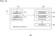
- FIG. 10 shows a configuration of the wireless relay apparatus 200.
- the wireless relay apparatus 200 includes a communication unit 210, a processing unit 250, and a recording unit 260.
- the communication unit 210 includes a first communication unit 212 and a second communication unit 214, and the processing unit 250 includes a sound quality evaluation unit 252 and a relay recording control unit 254.
- the communication unit 210 performs simplex wireless communication. That part of the communication unit 210 communicating with the terminal apparatus on the transmission side (e.g., the first terminal apparatus 100a) is the first communication unit 212, and the part communicating with the terminal apparatus on the receiving side (e.g., the second terminal apparatus 100b) is the second communication unit 214.
- the first communication unit 212 and the second communication unit 214 are configured as separate units for convenience, but they may be integrated.
- the processing unit 250 controls the operation of the wireless relay apparatus 200 using the recording unit 260.
- FIG. 11 is also used to describe the process of the wireless relay apparatus 200.
- FIG. 11 is a flowchart showing a communication procedure performed by the wireless relay apparatus 200.
- the first communication unit 212 receives a transmission request from the first terminal apparatus 100a. When the processing unit 250 receives the transmission request, it checks for an unused channel. When it is confirmed that an unused channel is available, the processing unit 250 allocates the first terminal apparatus 100a to the unused channel and causes the first communication unit 212 to transmit a transmission permission notice including the call ID. The first communication unit 212 transmits the transmission permission notice to the first terminal apparatus 100a.
- the first communication unit 212 receives the first sound signal with a call ID attached thereto from the first terminal apparatus 100a (S300).
- the second communication unit 214 transmits the first sound signal received by the first communication unit 212 the second terminal apparatus 100b as the second sound signal along with the call ID.
- the recording unit 260 is caused to record the first sound signal and the call ID received by the first communication unit 212.
- the recording unit 260 records the first sound signal and the call ID.
- the processing unit 250 measures the quality of the first sound signal received by the first communication unit 212.
- the quality of the first sound signal is, for example, BER, RSSI, and Broken Block Number, and known technologies are used for these measurements.
- the recording unit 260 records the tables shown in FIGS. 3A to 3B and FIG. 4A .
- the first communication unit 212 receives a transmission end signal from the first terminal apparatus 100a.
- the sound quality evaluation unit 252 checks the quality of the first sound signal recorded in the recording unit 260.
- the processing unit 250 causes the recording unit 260 to record the corresponding block number (S304).
- the processing unit 250 causes the recording unit 260 to record the corresponding block number (S308).
- step 308 is skipped.
- the sound quality evaluation unit 252 sets "OK” in “Broken Flag” when there is no problem with the quality of the first sound signal, sets “NG” in “Broken Flag” when the quality of the first sound signal is deteriorated, and sets “Lost” in “BrokenFlag” when the first sound signal cannot be acquired.
- the sound quality evaluation unit 252 determines that the quality of the first sound signal has a problem in the case the first sound signal is deteriorated, and in the case the first sound signal cannot be acquired.
- the sound quality evaluation unit 252 causes the first communication unit 212 to transmit a poor call status notice (S312).
- the first communication unit 212 transmits the poor call status notice to the first terminal apparatus 100a.
- the first communication unit 212 When the first communication unit 212 does not receive a retransmission confirmation request from the first terminal apparatus 100a (N in S314), the first communication unit 212 stands by. When the first communication unit 212 receives the retransmission confirmation request from the first terminal apparatus 100a (Y in S314), the sound quality evaluation unit 252 causes the first communication unit 212 to transmit a retransmission notice (S316). As shown in FIG. 4D , the retransmission notice includes the call ID and the block number of the first sound signal having a quality problem. That is, the sound quality evaluation unit 252 causes the first communication unit 212 to transmit a retransmission notice when the quality of the first sound signal received by the first communication unit 212 is lower than a threshold value. The first communication unit 212 transmits the retransmission notice to the first terminal apparatus 100a.
- the first communication unit 212 receives the transmission request from the first terminal apparatus 100a (S318).
- the first communication unit 212 transmits a transmission permission notice to the first terminal apparatus 100a (S320).
- the first communication unit 212 re-receives a first sound signal with a call ID attached thereto from the first terminal apparatus 100a (S322).
- the sound quality evaluation unit 252 causes the recording unit 260 to record the re-received first sound signal (S326).
- the first communication unit 212 transmits "OK" to the first terminal apparatus 100a to indicate a result of the first sound signal (S328). If the data integrity of the first sound signal is not found to be OK in the sound quality evaluation unit 252 (N in S324), the first communication unit 212 transmits "NG" to the first terminal apparatus 100a to indicate a result of the first sound signal (S330). When there is no problem with the quality of the first sound signal, on the other hand, i.e., when the call state is good (Y in S310), steps 312 to 330 are skipped.
- FIG. 12 is a flowchart illustrating another communication procedure performed by the wireless relay apparatus 200.
- the relay recording control unit 254 outputs control information including the call ID of the second sound signal transmitted last in time to the second communication unit 214.
- the control information is as shown in FIG. 6 .
- the second communication unit 214 periodically transmits control information to notify the terminal apparatus 100.
- the second terminal apparatus 100b transmits a list request to the wireless relay apparatus 200.
- the list request includes the last call ID.
- the second communication unit 214 receives the list request from the second terminal apparatus 100b (S350).
- the second communication unit 214 outputs the list request to the processing unit 250.
- the relay recording control unit 254 extracts the last call ID from the received list request.
- the last call ID is also called the last identifier.
- the relay recording control unit 254 generates a list of call IDs recorded in the recording unit 260 after the last call ID (S352).
- the relay recording control unit 254 outputs the list to the second communication unit 214.
- the second communication unit 214 transmits the list to the second terminal apparatus 100b (S354).
- the second communication unit 214 receives a playback request from the second terminal apparatus 100b that has received the list (S356).
- the playback request includes a call ID (transmission request identifier) for which the second terminal apparatus 100b requests playback from among the call IDs included in the list.
- the relay recording control unit 254 extracts the first sound signal corresponding to the call ID indicated in the received playback request from the recording unit 260.
- the relay recording control unit 254 outputs the extracted first sound signal to the second communication unit 214 as the second sound signal.
- the second communication unit 214 transmits the second sound signal to the second terminal apparatus 100b (S358).
- FIG. 13 shows a configuration of the second terminal apparatus 100b.
- the second terminal apparatus 100b includes a communication unit 110, a user control unit 120, a microphone 130, a speaker 140, a processing unit 150, and an identifier recording unit 170.
- the communication unit 110 includes a transmission unit 112 and a reception unit 114
- the processing unit 150 includes an area determination unit 154 and a retransmission control unit 156.
- the reception unit 114 receives the second sound signal with a call ID attached thereto from the wireless relay apparatus 200.
- the processing unit 150 plays back the sound based on the second sound signal and outputs the sound from the speaker 140.
- the processing unit 150 causes the identifier recording unit 170 to record the call ID received last in time by the reception unit 114 as the last call ID.
- the identifier recording unit 170 records the last call ID.
- FIG. 14 is a flowchart showing a communication procedure performed by the second terminal apparatus 100b. As described above, it is assumed that the second terminal apparatus 100b is moving from outside the second communication service area 10b toward the first communication service area 10a as shown in FIG. 1 .
- the area determination unit 154 determines whether the second terminal apparatus 100b is located in the communication service area 10 of the wireless relay apparatus 200. The area determination unit 154 determines that the second terminal apparatus 100b is located in the communication service area 10 when, for example, the second communication unit 214 receives a signal from the wireless relay apparatus 200, and determines that the second terminal apparatus 100b is not located in the communication service area 10 when the second communication unit 214 does not receive a signal from the wireless relay apparatus 200.
- the area determination unit 154 recognizes an entry into the zone of the communication service area 10 (S400).
- the second terminal apparatus 100b can recognize that it is within the zone of the communication service area 10 by receiving a control signal described later from the wireless relay apparatus 200, and the process of S400 is not necessarily essential.
- the second terminal apparatus 100b can know that it is positioned to exchange signals reliably with the wireless relay apparatus 200 by recognizing a difference between the first communication service area 10a and the second communication service area 10b by means of the area determination unit 154.
- the reception unit 114 receives, from the wireless relay apparatus 200, control information including the call ID of the second sound signal transmitted last in time from the wireless relay apparatus 200 (S402).
- the retransmission control unit 156 compares the call ID included in the control information received by the reception unit 114 with the last call ID recorded last in time in the identifier recording unit 170. When the call ID and the last call ID do not match (N in S404), the retransmission control unit 156 outputs a list request including the last call ID to the transmission unit 112.
- the transmission unit 112 transmits the list request to the wireless relay apparatus 200 (S406).
- the reception unit 114 receives the list from the wireless relay apparatus 200 (S408). As described above, the list shows the call ID recorded in the wireless relay apparatus 200 after the last call ID.
- the retransmission control unit 156 extracts the call ID included in the list. When a plurality of call IDs are not included in the list (N in S410), the retransmission control unit 156 outputs a playback request indicating the call ID included in the list to the transmission unit 112.
- the transmission unit 112 transmits the playback request to the wireless relay apparatus 200 (S412).
- the reception unit 114 re-receives the second sound signal with a call ID attached thereto from the wireless relay apparatus 200 (S414).
- the processing unit 150 plays back the sound based on the second sound signal (S416) and causes the speaker 140 to output the sound.
- the processing unit 150 performs a selective playback process (S418).
- the retransmission control unit 156 ends the process without causing the transmission unit 112 to transmit a list request.
- FIG. 15 is a flowchart showing a procedure for selective playback process performed by the second terminal apparatus 100b. This corresponds to the process of step 418 in FIG. 14 .
- the retransmission control unit 156 selects one or more call IDs for which playback is requested from among the plurality of call IDs included in the list (S450). Selection is made, for example, based on a selection instruction received by the user control unit 120 from the user. Further, the retransmission control unit 156 may automatically perform the selection.
- the retransmission control unit 156 outputs a playback request for the selected call ID to the transmission unit 112.
- the transmission unit 112 transmits the playback request to the wireless relay apparatus 200 (S452).
- the reception unit 114 re-receives the second sound signal with a call ID attached thereto from the wireless relay apparatus 200 (S454).
- the processing unit 150 reproduces the sound based on the second sound signal (S456) and causes the speaker 140 to output the sound.
- an identifier is transmitted to the first terminal apparatus when the quality of the received first sound signal is lower than a threshold value.
- the first sound signal is re-received from the first terminal apparatus thereby, the first sound signal re-received is recorded. Accordingly, the accurate first sound signal can be recorded. Further, since the accurate first sound signal is recorded, the accuracy of sound signal communication can be improved.
- a list of call IDs recorded after the last call ID is transmitted to the second terminal apparatus so that the call ID recorded after the last call ID can be recognized by the second terminal apparatus. Further, when the call ID included in the list is received, the second sound signal corresponding to the call ID is transmitted to the second terminal apparatus so that the accuracy of sound signal communication can be improved. Further, since the call ID of the second sound signal transmitted last in time is communicated, it is possible to cause the second terminal apparatus to confirm whether all call IDs have been received.
- the first sound signal with a call ID attached thereto is transmitted to the wireless relay apparatus and is also recorded in the recording unit.
- the first sound signal corresponding to the identifier is extracted from the recording unit and transmitted to the wireless relay unit. Accordingly, the accuracy of sound signal communication can be improved.
- the call ID included in the list is transmitted to the wireless relay apparatus so that it is possible to request retransmission of the second sound signal corresponding to the call ID. Further, since retransmission of the second sound signal corresponding to the call ID is requested, the accuracy of the sound signal communication can be improved. Further, when the call ID of the second sound signal transmitted last in time from the wireless relay apparatus matches the last call ID, the last call ID is not transmitted so that occurrence of unnecessary communication can be prevented.
- the accuracy of sound signal communication can be improved.
- 10 communication service area 100 terminal apparatus, 110 communication unit, 112 transmission unit, 114 reception unit, 120 user control unit, 130 microphone, 140 speaker, 150 processing unit, 152 retransmission control unit, 154 area determination unit, 156 retransmission control unit, 160 recording unit, 170 identifier recording unit, 200 wireless relay apparatus, 210 communication unit, 212 first communication unit, 214 second communication unit, 250 processing unit, 252 sound quality evaluation unit, 254 relay recording control unit, 260 recording unit, 1000 communication system.
Landscapes
- Engineering & Computer Science (AREA)
- Signal Processing (AREA)
- Computer Networks & Wireless Communication (AREA)
- Computer Vision & Pattern Recognition (AREA)
- Multimedia (AREA)
- Mobile Radio Communication Systems (AREA)
- Telephone Function (AREA)
- Telephonic Communication Services (AREA)
Abstract
Description
- The present invention relates to communication technology and, more particularly, to a wireless relay apparatus, a first terminal apparatus, a second terminal apparatus, and a communication system that performs communication of sound signals.
- In a communication system such as that of mobile communication, an answering machine system for terminal apparatuses is provided. The control station on the network side checks for connection of a terminal apparatus and notifies the terminal apparatus that there is a message when the terminal apparatus is connected (for example, PATENT LITERATURE 1).
- [PATENT LITERATURE 1]
JP H10-190847 - Since
patent literature 1 assumes individual calls, the control station can confirm whether the terminal apparatus is connected and can know from what point of time the terminal apparatus has not received a call. In a group call by simplex communication, however, it is difficult to confirm whether the terminal apparatus is connected. - The present invention addresses the issue described above, and a purpose thereof is to provide a technology for reliably performing communication of information signals exemplified by sound.
- A wireless relay apparatus according to an embodiment of the present invention includes: a first communication unit that receives a first sound signal with an identifier attached thereto from a first terminal apparatus; a recording unit that records the first sound signal and the identifier received by the first communication unit; and a relay recording control unit that, when the second communication unit receives the identifier received last in time by the second terminal apparatus from the second terminal apparatus as a last identifier, causes the second communication unit to transmit a list of identifiers recorded in the recording unit after the last identifier to the second terminal apparatus, and that, when the second communication unit receives the identifier included in the list from the second terminal apparatus as a transmission request identifier, extracts the first sound signal corresponding to the transmission request identifier from the recording unit and causes the second communication unit to transmit the first sound signal extracted to the second terminal apparatus as the second sound signal.
- Another embodiment of the present invention relates to a communication system. The communication system includes: a first terminal apparatus that transmits a first sound signal with an identifier attached thereto; a wireless relay apparatus that transmits the first sound signal as a second sound signal along with the identifier, when the first sound signal with the identifier attached thereto is received from the first terminal apparatus; and a second terminal apparatus that receives the second sound signal with the identifier attached thereto from the wireless relay apparatus. The wireless relay apparatus includes: a recording unit that records the first sound signal and the identifier received; a sound quality evaluation unit that evaluates a quality of the first sound signal received, that transmits the identifier to the first terminal apparatus as a retransmission request identifier, when an evaluation value is lower than a threshold value, and that replaces the first sound signal recorded in the recording unit with the first sound signal re-received, when the first sound signal with the retransmission request identifier attached thereto is re-received from the first terminal apparatus and when the evaluation value is equal to or higher than the threshold value: and a relay recording control unit that, when the identifier received last in time by the second terminal apparatus is received from the second terminal apparatus as a last identifier, transmits a list of identifiers recorded in the recording unit after the last identifier to the second terminal apparatus, and that, when the identifier included in the list is received from the second terminal apparatus as a transmission request identifier, extracts the first sound signal corresponding to the transmission request identifier from the recording unit and transmit the first sound signal extracted to the second terminal apparatus as the second sound signal.
- Optional combinations of the aforementioned constituting elements, and implementations of the embodiment in the form of methods, apparatuses, systems, recording mediums, and computer programs may also be practiced as additional modes of the present invention.
- According to the present invention, the accuracy of communication of sound signals can be improved.
-
-
FIG. 1 shows a configuration of a communication system according to an embodiment. -
FIG. 2 is a sequence chart showing a communication procedure performed by the first terminal apparatus and the wireless relay apparatus ofFIG. 1 . -
FIG. 3A to 3B show a data structure of a database stored in the wireless relay apparatus ofFIG. 1 . -
FIGS. 4A to 4D show an overview of the process in the wireless relay apparatus ofFIG. 1 . -
FIG. 5 is a sequence chart showing a communication procedure performed by the wireless relay apparatus and the second terminal apparatus ofFIG. 1 . -
FIG. 6 shows a data structure of another database stored in the wireless relay apparatus ofFIG. 1 . -
FIG. 7 shows a configuration of the first terminal apparatus ofFIG. 1 . -
FIG. 8 is a flowchart showing a communication procedure performed by the first terminal apparatus ofFIG. 7 . -
FIG. 9 is a flowchart showing a procedure for retransmission process performed by the first terminal apparatus ofFIG. 7 . -
FIG. 10 shows a configuration of the wireless relay apparatus ofFIG. 1 . -
FIG. 11 is a flowchart showing a communication procedure performed by the wireless relay apparatus ofFIG. 10 . -
FIG. 12 is a flowchart illustrating another communication procedure performed by the wireless relay apparatus ofFIG. 10 . -
FIG. 13 shows a configuration of the second terminal apparatus ofFIG. 1 . -
FIG. 14 is a flowchart showing a communication procedure performed by the second terminal apparatus ofFIG. 13 . -
FIG. 15 is a flowchart showing a procedure for selective playback process performed by the second terminal apparatus ofFIG. 13 . - Before describing the present invention in specific details, we will first describe an overview. When it is detected that a call cannot be made in a related-art system capable of bidirectional communication such as the telephone, the system can record a sound and automatically transmit the recorded sound when a call becomes enabled. On the other hand, the embodiment of the present invention relates to a simplex (unidirectional) communication system. For example, a terminal apparatus on the transmitting side transmits a sound signal (hereinafter referred to as a "first sound signal") to a wireless relay apparatus, and the wireless relay apparatus transmits the received first sound signal to the terminal apparatus on the receiving side as a second audio signal. When a group call is made, a plurality of terminal apparatuses on the receiving side are included.
- In simplex communication, signals cannot be received while a signal is being transmitted so that the terminal apparatus on the transmitting cannot recognize the signal reception status in the wireless relay apparatus or the terminal apparatus on the receiving side. In particular, even if there is a terminal apparatus on the receiving side that cannot receive radio waves from the wireless relay apparatus in a group call by simplex communication, the wireless relay apparatus cannot recognize from what point of time the terminal apparatus on the receiving side has not received a call. Furthermore, the point of time when reception is not made differs between the plurality of terminal apparatuses on the receiving side. That is, a technology for efficiently retransmitting calls to terminal apparatuses on the receiving side in various conditions is required. In addition, the terminal apparatus on the transmitting side does not detect whether the wireless relay apparatus was able to receive a signal normally from the terminal apparatus on the transmitting side. Therefore, the wireless relay apparatus is also required to be equipped with a technology that can reliably receive a signal from the terminal apparatus on the transmitting side and relay it to the terminal apparatus on the receiving side.
- The terminal apparatus on the transmitting side in this embodiment records the transmitted first sound signal, and the wireless relay apparatus records the received first sound signal. Furthermore, the first sound signal and the second sound signal are managed by identifiers (hereinafter referred to as a "call ID"). When the quality of the received first sound signal is low, the wireless relay apparatus reliably records the first sound signal reliably by requesting retransmission from the terminal apparatus on the transmitting side. When the terminal apparatus on the receiving end moves from outside a communication service area into a communication service area and connects to the wireless relay apparatus, the terminal apparatus transmits the call ID of the second sound signal received last in time when it was previously located in the communication service area (hereinafter referred to as a "last call ID") to the wireless relay apparatus. The wireless relay apparatus acquires the last call ID from the terminal apparatus on the receiving side and transmits the unreceived first sound signal to the terminal apparatus on the receiving side as the second sound signal, using the first sound signal as recorded. Thereby, reliable transmission from the first terminal apparatus to the wireless relay apparatus and reliable transmission from the wireless relay apparatus to the second terminal apparatus are realized.
-
FIG. 1 shows a configuration of acommunication system 1000. Thecommunication system 1000 includes a firstterminal apparatus 100a to athird terminal apparatus 100c, which are generically referred to as aterminal apparatus 100, and awireless relay apparatus 200. The number ofterminal apparatuses 100 included in thecommunication system 1000 is not limited to "3", and the number ofwireless relay apparatuses 200 is not limited to "1". In thecommunication system 1000, simplex communication is performed. - The
terminal apparatus 100 is, for example, a wireless apparatus capable of performing sound communication by PTT (Push to Talk). In PTT, theterminal apparatus 100 can transmit a sound signal while the PTT button of theterminal apparatus 100 is being pressed down. When the PTT button of theterminal apparatus 100 is not pressed down, on the other hand, theterminal apparatus 100 can receive a sound signal. By way of one example, the firstterminal apparatus 100a corresponds to the terminal apparatus on the transmitting side described above, and the secondterminal apparatus 100b and the thirdterminal apparatus 100c correspond to the terminal apparatus on the receiving side described above. - The
wireless relay apparatus 200 is a wireless device that relays communication between a plurality ofterminal apparatuses 100. The transmission output of thewireless relay apparatus 200 is often set to be larger than the transmission output of theterminal apparatus 100. A firstcommunication service area 10a is formed around thewireless relay apparatus 200, and a secondcommunication service area 10b is formed around the firstcommunication service area 10a. The firstcommunication service area 10a is an area in which communication from thewireless relay apparatus 200 to theterminal apparatus 100 and communication from theterminal apparatus 100 to thewireless relay apparatus 200 are possible. The secondcommunication service area 10b is an area in which communication from thewireless relay apparatus 200 to theterminal apparatus 100 is possible but communication from theterminal apparatus 100 to thewireless relay apparatus 200 is impossible. However, the boundary between the firstcommunication service area 10a and the secondcommunication service area 10b is not clear. The quality of communication from theterminal apparatus 100 to thewireless relay apparatus 200 gradually deteriorates as the terminal moves in a direction away from the firstcommunication service area 10a. - The first
terminal apparatus 100a transmits the first sound signal with a call ID attached thereto when the PTT button is pressed down. When thewireless relay apparatus 200 receives the first sound signal with the call ID attached thereto from the firstterminal apparatus 100a, thewireless relay apparatus 200 transmits the first sound signal as the second sound signal along with the call ID. When the secondterminal apparatus 100b and the thirdterminal apparatus 100c are located in the firstcommunication service area 10a or the secondcommunication service area 10b, the secondterminal apparatus 100b and the thirdterminal apparatus 100c receive the second sound signal with the call ID attached thereto from thewireless relay apparatus 200. In this way, a group call by the firstterminal apparatus 100a, the secondterminal apparatus 100b, and the thirdterminal apparatus 100c is performed. - In such a situation, it is preferable to eliminate miscalls in a group call, but it is desirable to transmit a sound signal even if a miscall occurs. Further, when simplex communication is performed, the user of the first
terminal apparatus 100a cannot know whether a miscall has occurred in the secondterminal apparatus 100b or in the thirdterminal apparatus 100c. Hereinafter, a process for solving this issue will be described, and the process is divided into the first process between the firstterminal apparatus 100a and thewireless relay apparatus 200 and the second process between thewireless relay apparatus 200 and the secondterminal apparatus 100b. - Since the second
terminal apparatus 100b is moving from outside the secondcommunication service area 10b toward the firstcommunication service area 10a as shown inFIG. 1 , it is presumed that a miscall may occur in the secondterminal apparatus 100b. On the other hand, the thirdterminal apparatus 100c stays in the firstcommunication service area 10a as shown inFIG. 1 so that it is presumed that a miscall does not occur in the thirdterminal apparatus 100c. Therefore, only the secondterminal apparatus 100b will be described hereinafter as the terminal apparatus on the receiving side. -
FIG. 2 is also used to describe the first process.FIG. 2 is a sequence chart showing a communication procedure performed by the firstterminal apparatus 100a and thewireless relay apparatus 200. The PTT button is pressed down in the firstterminal apparatus 100a (S10). The firstterminal apparatus 100a transmits a transmission request to thewireless relay apparatus 200 to request channel assignment (S12). S12 represents a case where radio waves have not reached thewireless relay apparatus 200. If there is no response from thewireless relay apparatus 200 within a preset time, for example, the firstterminal apparatus 100a transmits a transmission request again to thewireless relay apparatus 200 to request channel assignment (S14). When thewireless relay apparatus 200 receives a transmission request, it checks that an unused channel is available (S16). Thewireless relay apparatus 200 allocates the firstterminal apparatus 100a to the unused channel and transmits a transmission permission notice to the firstterminal apparatus 100a (S18). The firstterminal apparatus 100a starts transmitting and recording the sound and data (S20), and thewireless relay apparatus 200 starts receiving and recording the sound and data (S22). - The first
terminal apparatus 100a transmits the first sound signal to the wireless relay apparatus 200 (S24, S26). The firstterminal apparatus 100a records the first sound signal to be transmitted, and thewireless relay apparatus 200 records the received first sound signal.FIG. 3A to 3B show a data structure of a database stored in thewireless relay apparatus 200.FIG. 3A shows information on the first sound signal stored in thewireless relay apparatus 200. "Call ID" indicates the call ID, "Receive Time" indicates the time of reception by thewireless relay apparatus 200, "Source ID" indicates the ID of the transmission sourceterminal apparatus 100, and "Destination ID" indicates the ID of thedestination terminal apparatus 100. In the case of a group call, "Destination ID" is the ID of the destination group.FIG. 3B shows information on the quality of the first sound signal measured by thewireless relay apparatus 200. Quality measures include BER (Bit Error Rate), RSSI (Received Signal Strength Indicator), and Broken Block Number. Since known techniques may be used for these measurements, a description thereof is omitted here. -
FIGS. 4A to 4D show an overview of the process in thewireless relay apparatus 200.FIG. 4A shows information on the address of the first sound signal stored in thewireless relay apparatus 200. The address indicates a location where the first sound signal is stored in "Audio Data" ofFIG. 4B . "Audio Data" is an area in which the first sound signal is stored in arecording unit 260.FIGS. 4C to 4D will be described later, and reference is made back toFIG. 3 . The PTT button is turned off in the firstterminal apparatus 100a (S28). The firstterminal apparatus 100a transmits a transmission end notice to the wireless relay apparatus 200 (S30). When thewireless relay apparatus 200 receives the transmission end notice, thewireless relay apparatus 200 checks the quality of the recorded first sound signal (S32).FIG. 4C shows a result of checking the quality of the first sound signal. The sound signal in a call indicated by "Call ID" is divided into a plurality of blocks and recorded accordingly. The blocks are managed by sequential block numbers indicated by "Block Number". The quality of the sound signal is checked block by block. When there is no problem with the quality of the first sound signal, "OK" is set in "Broken Flag", and when the quality of the first sound signal is deteriorated, "NG" is set in "Broken Flag". Also, when the first sound signal cannot be acquired, "Lost" is set in "Broken Flag". The case where the quality of the first sound signal is deteriorated and the case where the first sound signal cannot be acquired represent cases where there is a problem with the quality of the first sound signal.FIG. 4D shows a result of extracting, fromFIG. 4C , information on the block ID associated with a problem with the quality of the first sound signal. For example, theblock number 004 is not found inFIG. 4C , and so it is detected that the sound signal of the block of the first sound signal having theblock number 004 could not be acquired. Reference is made back toFIG. 2 . - When there is a first sound signal having a quality problem, the
wireless relay apparatus 200 transmits a poor call status notice to the firstterminal apparatus 100a (S34). When the firstterminal apparatus 100a receives the poor call status notice, the firstterminal apparatus 100a transmits a retransmission confirmation request to the wireless relay apparatus 200 (S36). When thewireless relay apparatus 200 receives the retransmission confirmation request, thewireless relay apparatus 200 transmits a retransmission notice indicating the block of the first sound signal having a quality problem to the firstterminal apparatus 100a (S38). The firstterminal apparatus 100a constructs retransmission data so as to include the block indicated by the received retransmission notice (S40) and transmits the constructed retransmission data to thewireless relay apparatus 200 as the first sound signal (S42). - The
wireless relay apparatus 200 records the first sound signal (S44). Thewireless relay apparatus 200 transmits "OK" or "NG" information to the firstterminal apparatus 100a to indicate a result of the first sound signal (S46). The firstterminal apparatus 100a transmits a transmission end notice to the wireless relay apparatus 200 (S48), and thewireless relay apparatus 200 transmits "OK" information responsive to the transmission end notice to the firstterminal apparatus 100a. -
FIG. 5 is also used to describe the second process.FIG. 5 is a sequence chart showing a communication procedure performed by thewireless relay apparatus 200 and the secondterminal apparatus 100b. As described above, the secondterminal apparatus 100b moves from outside the secondcommunication service area 10b toward the firstcommunication service area 10a as shown inFIG. 1 and enters the zone of the secondcommunication service area 10b (S100). Thewireless relay apparatus 200 periodically transmits control information including the call ID of the second sound signal transmitted last in time (S102).FIG. 6 shows a data structure of another database stored in thewireless relay apparatus 200. The call ID of the second sound signal last transmitted in time from thewireless relay apparatus 200 is stored for each group. Hereinafter, one group is the subject of description. Reference is made back toFIG. 5 . - The second
terminal apparatus 100b checks the call ID included in the control information with the last call ID (S104). When the call ID and the last call ID do not match, the secondterminal apparatus 100b transmits a list request to the wireless relay apparatus 200 (S106). Since the secondterminal apparatus 100b is located in the secondcommunication service area 10b, the list request is not received by thewireless relay apparatus 200. When the secondterminal apparatus 100b enters the firstcommunication service area 10a, the list request from the secondterminal apparatus 100b is received by the wireless relay apparatus 200 (S108). Thewireless relay apparatus 200 generates a list (S110). Thewireless relay apparatus 200 transmits the list to the secondterminal apparatus 100b (S112, S114). - The second
terminal apparatus 100b receives the list (S116). The secondterminal apparatus 100b transmits a playback request indicating the call ID, from amon the call IDs included in the list, for which playback is requested to the wireless relay apparatus 200 (S118). Thewireless relay apparatus 200 transmits the second sound signal of the call ID indicated in the playback request to the secondterminal apparatus 100b (S120, S122). After transmitting the second sound signal, thewireless relay apparatus 200 transmits a transmission end notice to the secondterminal apparatus 100b (S124). The secondterminal apparatus 100b transmits "OK" information responsive to the transmission end notice to the wireless relay apparatus 200 (S126). The secondterminal apparatus 100b updates the last call ID (S128). - Hereinafter, the configuration of the first
terminal apparatus 100a, thewireless relay apparatus 200, and the secondterminal apparatus 100b in thecommunication system 1000 will be described in the order of (1) first process and (2) second process. -
FIG. 7 shows a configuration of the firstterminal apparatus 100a. The firstterminal apparatus 100a includes acommunication unit 110, auser control unit 120, amicrophone 130, aspeaker 140, aprocessing unit 150, and arecording unit 160. Thecommunication unit 110 includes atransmission unit 112 and areception unit 114, and theprocessing unit 150 includes aretransmission control unit 152. Thecommunication unit 110 performs simplex wireless communication. Therefore, thereception unit 114 does not receive a signal during a period when thetransmission unit 112 is transmitting a signal, and thetransmission unit 112 does not transmit a signal during a period when thereception unit 114 is receiving the signal. That is, one of thetransmission unit 112 and thereception unit 114 operates and the other stops. - The
user control unit 120 is configured by a button, a touch panel, or the like, and receives an input from the user. It should be noted here that the button corresponds to a PTT button, and theuser control unit 120 receives an instruction for PTT transmission in response to the PTT button being pressed down. On the other hand, theuser control unit 120 receives an end of transmission by PTT in response to the PTT button being released. Theuser control unit 120 outputs the received input to theprocessing unit 150. - The
microphone 130 acquires the sound from the user while the PTT button is being pressed down. Themicrophone 130 converts the sound into an electrical signal and outputs the sound in the form of the electrical signal (hereinafter also referred to as "sound") to theprocessing unit 150. Thespeaker 140 outputs the sound played back by theprocessing unit 150. - The
processing unit 150 controls the operation of the firstterminal apparatus 100a using therecording unit 160.FIGS. 8 and9 are also used to describe the process in theprocessing unit 150.FIG. 8 is a flowchart showing a communication procedure performed by the firstterminal apparatus 100a. When the PTT button is pressed down (S200), theprocessing unit 150 causes thetransmission unit 112 to transmit a transmission request. Thetransmission unit 112 transmits a transmission request to thewireless relay apparatus 200 according to an instruction from theprocessing unit 150. When thereception unit 114 receives a transmission permission notice from thewireless relay apparatus 200 as a result of the firstterminal apparatus 100a being allocated to an unused channel in the wireless relay apparatus 200 (Y in S202), theprocessing unit 150 acquires the call ID included in the transmission permission notice (S204). - The
processing unit 150 stores the call ID in therecording unit 160, generates the first sound signal based on the sound from themicrophone 130, and causes the first sound signal to be transmitted from the transmission unit 112 (S206). Thetransmission unit 112 transmits the first sound signal with the call ID attached thereto to thewireless relay apparatus 200. Further, theprocessing unit 150 causes therecording unit 160 to record the first sound signal block by block (S208) and stores a checksum for each block in the recording unit 160 (S210). Therecording unit 160 records the first sound signal and the call ID transmitted from thetransmission unit 112 and records the checksum and the attribute data. When the PTT is not turned off (N in S212), control returns to step 208. When the transmission is terminated as a result of PTT being turned off (Y in S212), on the other hand, thetransmission unit 112 transmits a transmission end notice to thewireless relay apparatus 200. - Since simplex communication is performed in the first
terminal apparatus 100a, the firstterminal apparatus 100a cannot recognize in real time whether the first sound signal is normally received by thewireless relay apparatus 200. When there is a problem with the quality of the first sound signal in thewireless relay apparatus 200, thewireless relay apparatus 200 transmits a poor call status notice to the firstterminal apparatus 100a. When thereception unit 114 receives the poor call status notice (Y in S214), theprocessing unit 150 performs a retransmission process (S216). When thereception unit 114 does not receive a poor call status notice (N in S214), the process is terminated. When thereception unit 114 does not receive a transmission permission notice from the wireless relay apparatus 200 (N in S202), on the other hand, steps 204 to 216 are skipped. -
FIG. 9 is a flowchart showing a procedure for retransmission process performed by the firstterminal apparatus 100a. This corresponds to step 216 inFIG. 8 . When thereception unit 114 receives a poor call status notice, theretransmission control unit 152 transmits a retransmission confirmation request from thetransmission unit 112 to the wireless relay apparatus 200 (S250). When thewireless relay apparatus 200 receives the retransmission confirmation request, thewireless relay apparatus 200 transmits a retransmission notice indicating the call ID (retransmission request identifier) and the block number of the first sound signal having a quality problem to the firstterminal apparatus 100a. - When the
reception unit 114 does not receive a retransmission notice from the wireless relay apparatus 200 (N in S252), thereception unit 114 stands by. When thereception unit 114 receives a retransmission notice from the wireless relay apparatus 200 (Y in S252), theretransmission control unit 152 acquires the call ID and the block number from the retransmission notice (S254). Theretransmission control unit 152 extracts the first sound signal corresponding to the acquired call ID and block number from therecording unit 160 and constructs retransmission data using the extracted first sound signal (S256). - The
retransmission control unit 152 causes thetransmission unit 112 to transmit a transmission request. Thetransmission unit 112 transmits a transmission request to thewireless relay apparatus 200 according to an instruction from the retransmission control unit 152 (S258). When thereception unit 114 receives the transmission permission notice from the wireless relay apparatus 200 (Y in S260), theretransmission control unit 152 causes thetransmission unit 112 to retransmit the first sound signal that embodies the retransmission data (S262). Thetransmission unit 112 retransmits the first sound signal to thewireless relay apparatus 200 according to an instruction from theretransmission control unit 152. When thereception unit 114 does not receive a transmission permission notice from the wireless relay apparatus 200 (N in S260), the process is terminated. -
FIG. 10 shows a configuration of thewireless relay apparatus 200. Thewireless relay apparatus 200 includes acommunication unit 210, aprocessing unit 250, and arecording unit 260. Thecommunication unit 210 includes afirst communication unit 212 and asecond communication unit 214, and theprocessing unit 250 includes a soundquality evaluation unit 252 and a relayrecording control unit 254. Thecommunication unit 210 performs simplex wireless communication. That part of thecommunication unit 210 communicating with the terminal apparatus on the transmission side (e.g., the firstterminal apparatus 100a) is thefirst communication unit 212, and the part communicating with the terminal apparatus on the receiving side (e.g., the secondterminal apparatus 100b) is thesecond communication unit 214. Thefirst communication unit 212 and thesecond communication unit 214 are configured as separate units for convenience, but they may be integrated. - The
processing unit 250 controls the operation of thewireless relay apparatus 200 using therecording unit 260.FIG. 11 is also used to describe the process of thewireless relay apparatus 200.FIG. 11 is a flowchart showing a communication procedure performed by thewireless relay apparatus 200. Thefirst communication unit 212 receives a transmission request from the firstterminal apparatus 100a. When theprocessing unit 250 receives the transmission request, it checks for an unused channel. When it is confirmed that an unused channel is available, theprocessing unit 250 allocates the firstterminal apparatus 100a to the unused channel and causes thefirst communication unit 212 to transmit a transmission permission notice including the call ID. Thefirst communication unit 212 transmits the transmission permission notice to the firstterminal apparatus 100a. - The
first communication unit 212 receives the first sound signal with a call ID attached thereto from the firstterminal apparatus 100a (S300). Thesecond communication unit 214 transmits the first sound signal received by thefirst communication unit 212 the secondterminal apparatus 100b as the second sound signal along with the call ID. Therecording unit 260 is caused to record the first sound signal and the call ID received by thefirst communication unit 212. Therecording unit 260 records the first sound signal and the call ID. - The
processing unit 250 measures the quality of the first sound signal received by thefirst communication unit 212. As described above, the quality of the first sound signal is, for example, BER, RSSI, and Broken Block Number, and known technologies are used for these measurements. As a result of such a process, therecording unit 260 records the tables shown inFIGS. 3A to 3B andFIG. 4A . - The
first communication unit 212 receives a transmission end signal from the firstterminal apparatus 100a. When the soundquality evaluation unit 252 receives the transmission end notice, the soundquality evaluation unit 252 checks the quality of the first sound signal recorded in therecording unit 260. When the first sound signal is damaged (Y in S302), theprocessing unit 250 causes therecording unit 260 to record the corresponding block number (S304). When the first sound signal is not damaged (N in S302) but is missing (Y in S306), theprocessing unit 250 causes therecording unit 260 to record the corresponding block number (S308). When the first sound signal is not missing (N in S306), step 308 is skipped. - As shown in
FIG. 4C , the soundquality evaluation unit 252 sets "OK" in "Broken Flag" when there is no problem with the quality of the first sound signal, sets "NG" in "Broken Flag" when the quality of the first sound signal is deteriorated, and sets "Lost" in "BrokenFlag" when the first sound signal cannot be acquired. The soundquality evaluation unit 252 determines that the quality of the first sound signal has a problem in the case the first sound signal is deteriorated, and in the case the first sound signal cannot be acquired. When there is a problem with the quality of the first sound signal, i.e., when the call state is not good (N in S310), the soundquality evaluation unit 252 causes thefirst communication unit 212 to transmit a poor call status notice (S312). Thefirst communication unit 212 transmits the poor call status notice to the firstterminal apparatus 100a. - When the
first communication unit 212 does not receive a retransmission confirmation request from the firstterminal apparatus 100a (N in S314), thefirst communication unit 212 stands by. When thefirst communication unit 212 receives the retransmission confirmation request from the firstterminal apparatus 100a (Y in S314), the soundquality evaluation unit 252 causes thefirst communication unit 212 to transmit a retransmission notice (S316). As shown inFIG. 4D , the retransmission notice includes the call ID and the block number of the first sound signal having a quality problem. That is, the soundquality evaluation unit 252 causes thefirst communication unit 212 to transmit a retransmission notice when the quality of the first sound signal received by thefirst communication unit 212 is lower than a threshold value. Thefirst communication unit 212 transmits the retransmission notice to the firstterminal apparatus 100a. - The
first communication unit 212 receives the transmission request from the firstterminal apparatus 100a (S318). Thefirst communication unit 212 transmits a transmission permission notice to the firstterminal apparatus 100a (S320). Thefirst communication unit 212 re-receives a first sound signal with a call ID attached thereto from the firstterminal apparatus 100a (S322). When the data integrity, which indicates whether the re-received first sound signal matches the call ID and the block number included in the retransmission notice and whether the sound quality does not have a problem, is OK (Y in S324), the soundquality evaluation unit 252 causes therecording unit 260 to record the re-received first sound signal (S326). This corresponds to replacing the first sound signal already recorded in therecording unit 260 with the first sound signal re-received by thefirst communication unit 212. Thefirst communication unit 212 transmits "OK" to the firstterminal apparatus 100a to indicate a result of the first sound signal (S328). If the data integrity of the first sound signal is not found to be OK in the sound quality evaluation unit 252 (N in S324), thefirst communication unit 212 transmits "NG" to the firstterminal apparatus 100a to indicate a result of the first sound signal (S330). When there is no problem with the quality of the first sound signal, on the other hand, i.e., when the call state is good (Y in S310), steps 312 to 330 are skipped. -
FIG. 12 is a flowchart illustrating another communication procedure performed by thewireless relay apparatus 200. The relayrecording control unit 254 outputs control information including the call ID of the second sound signal transmitted last in time to thesecond communication unit 214. The control information is as shown inFIG. 6 . Thesecond communication unit 214 periodically transmits control information to notify theterminal apparatus 100. When the call ID included in the control information and the last call ID do not match in the secondterminal apparatus 100b that has received the control information, the secondterminal apparatus 100b transmits a list request to thewireless relay apparatus 200. The list request includes the last call ID. Thesecond communication unit 214 receives the list request from the secondterminal apparatus 100b (S350). Thesecond communication unit 214 outputs the list request to theprocessing unit 250. - The relay
recording control unit 254 extracts the last call ID from the received list request. The last call ID is also called the last identifier. The relayrecording control unit 254 generates a list of call IDs recorded in therecording unit 260 after the last call ID (S352). The relayrecording control unit 254 outputs the list to thesecond communication unit 214. Thesecond communication unit 214 transmits the list to the secondterminal apparatus 100b (S354). - The
second communication unit 214 receives a playback request from the secondterminal apparatus 100b that has received the list (S356). The playback request includes a call ID (transmission request identifier) for which the secondterminal apparatus 100b requests playback from among the call IDs included in the list. The relayrecording control unit 254 extracts the first sound signal corresponding to the call ID indicated in the received playback request from therecording unit 260. The relayrecording control unit 254 outputs the extracted first sound signal to thesecond communication unit 214 as the second sound signal. Thesecond communication unit 214 transmits the second sound signal to the secondterminal apparatus 100b (S358). -
FIG. 13 shows a configuration of the secondterminal apparatus 100b. The secondterminal apparatus 100b includes acommunication unit 110, auser control unit 120, amicrophone 130, aspeaker 140, aprocessing unit 150, and anidentifier recording unit 170. Thecommunication unit 110 includes atransmission unit 112 and areception unit 114, and theprocessing unit 150 includes anarea determination unit 154 and aretransmission control unit 156. To make the description clear, the firstterminal apparatus 100a and the secondterminal apparatus 100b are assumed to be configured differently, but they may have a common configuration as theterminal apparatus 100. Thereception unit 114 receives the second sound signal with a call ID attached thereto from thewireless relay apparatus 200. Theprocessing unit 150 plays back the sound based on the second sound signal and outputs the sound from thespeaker 140. Theprocessing unit 150 causes theidentifier recording unit 170 to record the call ID received last in time by thereception unit 114 as the last call ID. Theidentifier recording unit 170 records the last call ID. -
FIG. 14 is a flowchart showing a communication procedure performed by the secondterminal apparatus 100b. As described above, it is assumed that the secondterminal apparatus 100b is moving from outside the secondcommunication service area 10b toward the firstcommunication service area 10a as shown inFIG. 1 . Thearea determination unit 154 determines whether the secondterminal apparatus 100b is located in thecommunication service area 10 of thewireless relay apparatus 200. Thearea determination unit 154 determines that the secondterminal apparatus 100b is located in thecommunication service area 10 when, for example, thesecond communication unit 214 receives a signal from thewireless relay apparatus 200, and determines that the secondterminal apparatus 100b is not located in thecommunication service area 10 when thesecond communication unit 214 does not receive a signal from thewireless relay apparatus 200. As a result of the movement from outside the secondcommunication service area 10b toward the firstcommunication service area 10a, thearea determination unit 154 recognizes an entry into the zone of the communication service area 10 (S400). However, the secondterminal apparatus 100b can recognize that it is within the zone of thecommunication service area 10 by receiving a control signal described later from thewireless relay apparatus 200, and the process of S400 is not necessarily essential. The secondterminal apparatus 100b can know that it is positioned to exchange signals reliably with thewireless relay apparatus 200 by recognizing a difference between the firstcommunication service area 10a and the secondcommunication service area 10b by means of thearea determination unit 154. - The
reception unit 114 receives, from thewireless relay apparatus 200, control information including the call ID of the second sound signal transmitted last in time from the wireless relay apparatus 200 (S402). Theretransmission control unit 156 compares the call ID included in the control information received by thereception unit 114 with the last call ID recorded last in time in theidentifier recording unit 170. When the call ID and the last call ID do not match (N in S404), theretransmission control unit 156 outputs a list request including the last call ID to thetransmission unit 112. Thetransmission unit 112 transmits the list request to the wireless relay apparatus 200 (S406). - The
reception unit 114 receives the list from the wireless relay apparatus 200 (S408). As described above, the list shows the call ID recorded in thewireless relay apparatus 200 after the last call ID. Theretransmission control unit 156 extracts the call ID included in the list. When a plurality of call IDs are not included in the list (N in S410), theretransmission control unit 156 outputs a playback request indicating the call ID included in the list to thetransmission unit 112. Thetransmission unit 112 transmits the playback request to the wireless relay apparatus 200 (S412). Thereception unit 114 re-receives the second sound signal with a call ID attached thereto from the wireless relay apparatus 200 (S414). Theprocessing unit 150 plays back the sound based on the second sound signal (S416) and causes thespeaker 140 to output the sound. When a plurality of call IDs are included in the list (Y in S410), theprocessing unit 150 performs a selective playback process (S418). When the call ID and the last call ID match (Y in S404), on the other hand, theretransmission control unit 156 ends the process without causing thetransmission unit 112 to transmit a list request. -
FIG. 15 is a flowchart showing a procedure for selective playback process performed by the secondterminal apparatus 100b. This corresponds to the process of step 418 inFIG. 14 . Theretransmission control unit 156 selects one or more call IDs for which playback is requested from among the plurality of call IDs included in the list (S450). Selection is made, for example, based on a selection instruction received by theuser control unit 120 from the user. Further, theretransmission control unit 156 may automatically perform the selection. Theretransmission control unit 156 outputs a playback request for the selected call ID to thetransmission unit 112. Thetransmission unit 112 transmits the playback request to the wireless relay apparatus 200 (S452). Thereception unit 114 re-receives the second sound signal with a call ID attached thereto from the wireless relay apparatus 200 (S454). Theprocessing unit 150 reproduces the sound based on the second sound signal (S456) and causes thespeaker 140 to output the sound. - The features are implemented in hardware such as a CPU, a memory, or other LSIs, of any computer and in software such as a program loaded into a memory. The figures depict functional blocks implemented by the cooperation of these elements. Therefore, it will be understood by those skilled in the art that these functional blocks may be implemented in a variety of manners by hardware only, software only, or by a combination of hardware and software.
- According to this embodiment, an identifier is transmitted to the first terminal apparatus when the quality of the received first sound signal is lower than a threshold value. When the first sound signal is re-received from the first terminal apparatus thereby, the first sound signal re-received is recorded. Accordingly, the accurate first sound signal can be recorded. Further, since the accurate first sound signal is recorded, the accuracy of sound signal communication can be improved. When the last call ID is received, a list of call IDs recorded after the last call ID is transmitted to the second terminal apparatus so that the call ID recorded after the last call ID can be recognized by the second terminal apparatus. Further, when the call ID included in the list is received, the second sound signal corresponding to the call ID is transmitted to the second terminal apparatus so that the accuracy of sound signal communication can be improved. Further, since the call ID of the second sound signal transmitted last in time is communicated, it is possible to cause the second terminal apparatus to confirm whether all call IDs have been received.
- Further, the first sound signal with a call ID attached thereto is transmitted to the wireless relay apparatus and is also recorded in the recording unit. When the identifier is received from the wireless relay apparatus, the first sound signal corresponding to the identifier is extracted from the recording unit and transmitted to the wireless relay unit. Accordingly, the accuracy of sound signal communication can be improved. Further, when a list of call IDs recorded in the wireless relay apparatus after the last call ID is received, the call ID included in the list is transmitted to the wireless relay apparatus so that it is possible to request retransmission of the second sound signal corresponding to the call ID. Further, since retransmission of the second sound signal corresponding to the call ID is requested, the accuracy of the sound signal communication can be improved. Further, when the call ID of the second sound signal transmitted last in time from the wireless relay apparatus matches the last call ID, the last call ID is not transmitted so that occurrence of unnecessary communication can be prevented.
- Given above is a description based on an embodiment. In the embodiment, a sound signal has been discussed, but the embodiment is also applicable to an information signal such as a data signal. The embodiment is intended to be illustrative only and it will be understood by those skilled in the art that various modifications to combinations of constituting elements and processes are possible and that such modifications are also within the scope of the present invention.
- According to the present invention, the accuracy of sound signal communication can be improved.
- 10 communication service area, 100 terminal apparatus, 110 communication unit, 112 transmission unit, 114 reception unit, 120 user control unit, 130 microphone, 140 speaker, 150 processing unit, 152 retransmission control unit, 154 area determination unit, 156 retransmission control unit, 160 recording unit, 170 identifier recording unit, 200 wireless relay apparatus, 210 communication unit, 212 first communication unit, 214 second communication unit, 250 processing unit, 252 sound quality evaluation unit, 254 relay recording control unit, 260 recording unit, 1000 communication system.
Claims (5)
- A wireless relay apparatus comprising:a first communication unit that receives a first sound signal with an identifier attached thereto from a first terminal apparatus;a second communication unit that transmits the first sound signal received by the first communication unit to a second terminal apparatus as a second sound signal along with the identifier;a recording unit that records the first sound signal and the identifier received by the first communication unit; anda relay recording control unit that, when the second communication unit receives the identifier received last in time by the second terminal apparatus from the second terminal apparatus as a last identifier, causes the second communication unit to transmit a list of identifiers recorded in the recording unit after the last identifier to the second terminal apparatus, and that, when the second communication unit receives the identifier included in the list from the second terminal apparatus as a transmission request identifier, extracts the first sound signal corresponding to the transmission request identifier from the recording unit and causes the second communication unit to transmit the first sound signal extracted to the second terminal apparatus as the second sound signal.
- The wireless relay apparatus according to claim 1, further comprising:
a sound quality evaluation unit that evaluates a quality of the first sound signal received by the first communication unit, that transmits the identifier of the first sound signal from the first communication unit to the first terminal apparatus as a retransmission request identifier, when an evaluation value is lower than a threshold value, and that replaces the first sound signal corresponding to the retransmission request identifier recorded in the recording unit with the first sound signal re-received, when the first communication unit re-receives the first sound signal with the retransmission request identifier attached thereto and when the evaluation value is equal to or higher than the threshold value. - A first terminal apparatus that communicates with the wireless relay apparatus according to claim 2, the first terminal apparatus comprising:a transmission unit that transmits the first sound signal with the identifier attached thereto to the wireless relay apparatus;a recording unit that records the first sound signal and the identifier transmitted from the transmission unit;a reception unit that receives the retransmission request identifier from the wireless relay apparatus; anda retransmission control unit that, when the reception unit receives the retransmission request identifier, extracts the first sound signal corresponding to the retransmission request identifier from the recording unit and causes the transmission unit to re-transmit the first sound signal extracted.
- A second terminal apparatus that communicates with the wireless relay apparatus according to claim 1 or 2, the second terminal apparatus comprising:a reception unit that receives the second sound signal with the identifier attached thereto from the wireless relay apparatus;an identifier recording unit that records the identifier received by the reception unit;a transmission unit that transmits the identifier recorded last in time in the identifier recording unit to the wireless relay apparatus as the last identifier; anda retransmission control unit that, when the reception unit receives a list of identifiers recorded in the wireless relay apparatus after the last identifier from the wireless relay apparatus, causes the transmission unit to transmit the identifier included in the list to the wireless relay apparatus as a transmission request identifier,wherein the reception unit re-receives the second sound signal with the transmission request identifier attached thereto from the wireless relay apparatus.
- A communication system comprising:a first terminal apparatus that transmits a first sound signal with an identifier attached thereto;a wireless relay apparatus that transmits the first sound signal as a second sound signal along with the identifier, when the first sound signal with the identifier attached thereto is received from the first terminal apparatus; anda second terminal apparatus that receives the second sound signal with the identifier attached thereto from the wireless relay apparatus,wherein the wireless relay apparatus includes:a recording unit that records the first sound signal and the identifier received;a sound quality evaluation unit that evaluates a quality of the first sound signal received, that transmits the identifier to the first terminal apparatus as a retransmission request identifier, when an evaluation value is lower than a threshold value, and that replaces the first sound signal recorded in the recording unit with the first sound signal re-received, when the first sound signal with the retransmission request identifier attached thereto is re-received from the first terminal apparatus and when the evaluation value is equal to or higher than the threshold value: anda relay recording control unit that, when the identifier received last in time by the second terminal apparatus is received from the second terminal apparatus as a last identifier, transmits a list of identifiers recorded in the recording unit after the last identifier to the second terminal apparatus, and that, when the identifier included in the list is received from the second terminal apparatus as a transmission request identifier, extracts the first sound signal corresponding to the transmission request identifier from the recording unit and transmit the first sound signal extracted to the second terminal apparatus as the second sound signal.
Applications Claiming Priority (2)
| Application Number | Priority Date | Filing Date | Title |
|---|---|---|---|
| JP2021105517A JP7632116B2 (en) | 2021-06-25 | 2021-06-25 | Wireless relay device, first terminal device, second terminal device, and communication system |
| PCT/JP2022/009740 WO2022270026A1 (en) | 2021-06-25 | 2022-03-07 | Wireless relay device, first terminal device, second terminal device, communication system |
Publications (3)
| Publication Number | Publication Date |
|---|---|
| EP4362442A1 true EP4362442A1 (en) | 2024-05-01 |
| EP4362442A4 EP4362442A4 (en) | 2024-10-23 |
| EP4362442B1 EP4362442B1 (en) | 2025-11-26 |
Family
ID=84544872
Family Applications (1)
| Application Number | Title | Priority Date | Filing Date |
|---|---|---|---|
| EP22827947.7A Active EP4362442B1 (en) | 2021-06-25 | 2022-03-07 | Wireless relay device, first terminal device, second terminal device, communication system |
Country Status (4)
| Country | Link |
|---|---|
| US (1) | US12609756B2 (en) |
| EP (1) | EP4362442B1 (en) |
| JP (2) | JP7632116B2 (en) |
| WO (1) | WO2022270026A1 (en) |
Family Cites Families (18)
| Publication number | Priority date | Publication date | Assignee | Title |
|---|---|---|---|---|
| JPH10190847A (en) | 1996-12-20 | 1998-07-21 | Kokusai Electric Co Ltd | Answering machine |
| JP4072650B2 (en) * | 1997-10-20 | 2008-04-09 | ソニー株式会社 | Information communication method, information communication system, portable radio communication terminal, and server apparatus |
| JP3943417B2 (en) * | 2002-03-07 | 2007-07-11 | 株式会社エヌ・ティ・ティ・ドコモ | Answering machine service providing system, answering machine service providing method, communication device, answering machine service providing apparatus |
| US20060159238A1 (en) * | 2004-12-28 | 2006-07-20 | Takashi Akita | Voice talk system, voice talk control apparatus, voice talk control method, and voice talk control program |
| JP2006238132A (en) * | 2005-02-25 | 2006-09-07 | Yamaha Corp | Apparatus and program for controlling incoming call |
| JP4631603B2 (en) * | 2005-08-24 | 2011-02-16 | 日本電気株式会社 | Audio data reproduction system, reproduction method, server apparatus, and program in PoC service |
| JP4502942B2 (en) * | 2005-11-29 | 2010-07-14 | 富士通株式会社 | COMMUNICATION METHOD, COMMUNICATION SYSTEM, COMMUNICATION DEVICE, AND COMPUTER PROGRAM |
| JP4750669B2 (en) * | 2006-10-20 | 2011-08-17 | ソフトバンクモバイル株式会社 | Communication terminal, communication method, and communication program |
| JP4840099B2 (en) * | 2006-11-20 | 2011-12-21 | 富士通株式会社 | Call server, call system, transfer processing device, and transfer processing program |
| WO2008140055A1 (en) * | 2007-05-14 | 2008-11-20 | Nec Corporation | Half-duplex communication system, half-duplex communication apparatus, communication content confirming method, and program thereof |
| JP2009053758A (en) * | 2007-08-23 | 2009-03-12 | Toshiba Corp | Communication terminal device |
| JP2013239975A (en) * | 2012-05-16 | 2013-11-28 | Ntt Docomo Inc | Voice transfer system and voice transfer method |
| WO2015068663A1 (en) * | 2013-11-07 | 2015-05-14 | アイコム株式会社 | Relay device, voice communication system, program, and method for relaying voice signal |
| EP3209085A4 (en) * | 2015-01-17 | 2017-12-06 | Huawei Technologies Co., Ltd. | Call setup method and system and user equipment |
| JP6588306B2 (en) * | 2015-10-28 | 2019-10-09 | 株式会社オービックビジネスコンサルタント | Information processing apparatus, information processing method, and program |
| US20190208410A1 (en) * | 2017-05-17 | 2019-07-04 | Tink Labs Limited | Systems, devices, and methods for managing communications of one or more computing devices |
| JP6407461B1 (en) * | 2018-02-27 | 2018-10-17 | 株式会社シアンス・アール | Signal processing apparatus, communication system, method implemented in signal processing apparatus, and program executed in signal processing apparatus |
| US11044327B2 (en) * | 2018-06-13 | 2021-06-22 | Verizon Patent And Licensing Inc | Systems and methods for wireless service migration |
-
2021
- 2021-06-25 JP JP2021105517A patent/JP7632116B2/en active Active
-
2022
- 2022-03-07 WO PCT/JP2022/009740 patent/WO2022270026A1/en not_active Ceased
- 2022-03-07 EP EP22827947.7A patent/EP4362442B1/en active Active
-
2023
- 2023-12-22 US US18/394,454 patent/US12609756B2/en active Active
-
2025
- 2025-01-31 JP JP2025014905A patent/JP7779414B2/en active Active
Also Published As
| Publication number | Publication date |
|---|---|
| EP4362442B1 (en) | 2025-11-26 |
| US12609756B2 (en) | 2026-04-21 |
| US20240129021A1 (en) | 2024-04-18 |
| JP7632116B2 (en) | 2025-02-19 |
| EP4362442A4 (en) | 2024-10-23 |
| JP7779414B2 (en) | 2025-12-03 |
| WO2022270026A1 (en) | 2022-12-29 |
| JP2023004051A (en) | 2023-01-17 |
| JP2025062005A (en) | 2025-04-11 |
Similar Documents
| Publication | Publication Date | Title |
|---|---|---|
| US4659878A (en) | Method and apparatus for interference free communications between a remote handset and a host subscriber unit in a Cellular Radio Telephone System | |
| US7839837B2 (en) | Asynchronous speech data communication system and communication method therefor | |
| CN112994854A (en) | Data receiving method, device and equipment of Bluetooth headset and storage medium | |
| CN100375547C (en) | Optimizing talk burst control process in a PTT communication network | |
| CN114501412B (en) | Bluetooth protocol data packet loss compensation method based on double-ear connection | |
| US20230189201A1 (en) | Information transmission method and related device | |
| US20160021517A1 (en) | Terminal apparatus communicating among a plurality of terminal apparatuses within a group, communication system, and communication method | |
| US11528764B2 (en) | Data communication method and system, electronic device, chip and storage medium | |
| US10033476B2 (en) | Apparatus and method for acquiring synchronization in mobile communication system | |
| EP4362442B1 (en) | Wireless relay device, first terminal device, second terminal device, communication system | |
| JPH0923205A (en) | Digital wireless communication device | |
| US20080220753A1 (en) | Mobile communication device, communication system and communication method | |
| CN106464449A (en) | Information transmission method and device | |
| KR101428092B1 (en) | In-Vehicle Call Control System and Method Thereof | |
| US20250392372A1 (en) | Communication apparatus and communication method using multiple wireless communication systems | |
| CN102082878A (en) | Method and device for detecting false circuit connection | |
| CN110875760B (en) | Communication method and device | |
| JP4868374B2 (en) | COMMUNICATION SYSTEM, CALL CONTROL DEVICE, BASE STATION DEVICE, AND COMPUTER PROGRAM | |
| US20250301493A1 (en) | Communication system that provides voice calls | |
| JP2003009236A (en) | Wireless device | |
| JP4276251B2 (en) | Mobile communication terminal and mobile communication terminal control method. | |
| CN112637425B (en) | Group member call state query method based on multi-mode terminal | |
| JP6924591B2 (en) | Wireless communication system and wireless communication device | |
| CN120659111A (en) | Method for sending message and Bluetooth headset | |
| KR20090022167A (en) | Data transmission method and Bluetooth terminal |
Legal Events
| Date | Code | Title | Description |
|---|---|---|---|
| STAA | Information on the status of an ep patent application or granted ep patent |
Free format text: STATUS: THE INTERNATIONAL PUBLICATION HAS BEEN MADE |
|
| PUAI | Public reference made under article 153(3) epc to a published international application that has entered the european phase |
Free format text: ORIGINAL CODE: 0009012 |
|
| STAA | Information on the status of an ep patent application or granted ep patent |
Free format text: STATUS: REQUEST FOR EXAMINATION WAS MADE |
|
| 17P | Request for examination filed |
Effective date: 20240116 |
|
| AK | Designated contracting states |
Kind code of ref document: A1 Designated state(s): AL AT BE BG CH CY CZ DE DK EE ES FI FR GB GR HR HU IE IS IT LI LT LU LV MC MK MT NL NO PL PT RO RS SE SI SK SM TR |
|
| DAV | Request for validation of the european patent (deleted) | ||
| DAX | Request for extension of the european patent (deleted) | ||
| A4 | Supplementary search report drawn up and despatched |
Effective date: 20240923 |
|
| RIC1 | Information provided on ipc code assigned before grant |
Ipc: H04M 1/00 20060101ALI20240917BHEP Ipc: H04W 88/18 20090101ALI20240917BHEP Ipc: H04W 4/10 20090101ALI20240917BHEP Ipc: H04M 3/42 20060101AFI20240917BHEP |
|
| GRAP | Despatch of communication of intention to grant a patent |
Free format text: ORIGINAL CODE: EPIDOSNIGR1 |
|
| STAA | Information on the status of an ep patent application or granted ep patent |
Free format text: STATUS: GRANT OF PATENT IS INTENDED |
|
| RIC1 | Information provided on ipc code assigned before grant |
Ipc: H04B 7/155 20060101ALI20250526BHEP Ipc: H04W 88/04 20090101ALI20250526BHEP Ipc: H04W 4/10 20090101ALI20250526BHEP Ipc: H04M 3/56 20060101ALI20250526BHEP Ipc: H04M 3/42 20060101AFI20250526BHEP |
|
| INTG | Intention to grant announced |
Effective date: 20250616 |
|
| GRAS | Grant fee paid |
Free format text: ORIGINAL CODE: EPIDOSNIGR3 |
|
| GRAA | (expected) grant |
Free format text: ORIGINAL CODE: 0009210 |
|
| STAA | Information on the status of an ep patent application or granted ep patent |
Free format text: STATUS: THE PATENT HAS BEEN GRANTED |
|
| RAP3 | Party data changed (applicant data changed or rights of an application transferred) |
Owner name: JVCKENWOOD CORPORATION |
|
| AK | Designated contracting states |
Kind code of ref document: B1 Designated state(s): AL AT BE BG CH CY CZ DE DK EE ES FI FR GB GR HR HU IE IS IT LI LT LU LV MC MK MT NL NO PL PT RO RS SE SI SK SM TR |
|
| REG | Reference to a national code |
Ref country code: CH Ref legal event code: F10 Free format text: ST27 STATUS EVENT CODE: U-0-0-F10-F00 (AS PROVIDED BY THE NATIONAL OFFICE) Effective date: 20251126 Ref country code: GB Ref legal event code: FG4D |
|
| REG | Reference to a national code |
Ref country code: DE Ref legal event code: R096 Ref document number: 602022025798 Country of ref document: DE |
|
| REG | Reference to a national code |
Ref country code: IE Ref legal event code: FG4D |
|
| REG | Reference to a national code |
Ref country code: NL Ref legal event code: MP Effective date: 20251126 |
|
| PGFP | Annual fee paid to national office [announced via postgrant information from national office to epo] |
Ref country code: GB Payment date: 20260202 Year of fee payment: 5 |
|
| PG25 | Lapsed in a contracting state [announced via postgrant information from national office to epo] |
Ref country code: ES Free format text: LAPSE BECAUSE OF FAILURE TO SUBMIT A TRANSLATION OF THE DESCRIPTION OR TO PAY THE FEE WITHIN THE PRESCRIBED TIME-LIMIT Effective date: 20251126 |
|
| REG | Reference to a national code |
Ref country code: LT Ref legal event code: MG9D |
|
| PG25 | Lapsed in a contracting state [announced via postgrant information from national office to epo] |
Ref country code: NO Free format text: LAPSE BECAUSE OF FAILURE TO SUBMIT A TRANSLATION OF THE DESCRIPTION OR TO PAY THE FEE WITHIN THE PRESCRIBED TIME-LIMIT Effective date: 20260226 |
|
| PGFP | Annual fee paid to national office [announced via postgrant information from national office to epo] |
Ref country code: DE Payment date: 20260128 Year of fee payment: 5 |
|
| PG25 | Lapsed in a contracting state [announced via postgrant information from national office to epo] |
Ref country code: FI Free format text: LAPSE BECAUSE OF FAILURE TO SUBMIT A TRANSLATION OF THE DESCRIPTION OR TO PAY THE FEE WITHIN THE PRESCRIBED TIME-LIMIT Effective date: 20251126 Ref country code: HR Free format text: LAPSE BECAUSE OF FAILURE TO SUBMIT A TRANSLATION OF THE DESCRIPTION OR TO PAY THE FEE WITHIN THE PRESCRIBED TIME-LIMIT Effective date: 20251126 Ref country code: AT Free format text: LAPSE BECAUSE OF FAILURE TO SUBMIT A TRANSLATION OF THE DESCRIPTION OR TO PAY THE FEE WITHIN THE PRESCRIBED TIME-LIMIT Effective date: 20251126 |
|
| PGFP | Annual fee paid to national office [announced via postgrant information from national office to epo] |
Ref country code: AT Payment date: 20260301 Year of fee payment: 5 |
|
| REG | Reference to a national code |
Ref country code: AT Ref legal event code: MK05 Ref document number: 1862309 Country of ref document: AT Kind code of ref document: T Effective date: 20251126 |
|
| PG25 | Lapsed in a contracting state [announced via postgrant information from national office to epo] |
Ref country code: NL Free format text: LAPSE BECAUSE OF FAILURE TO SUBMIT A TRANSLATION OF THE DESCRIPTION OR TO PAY THE FEE WITHIN THE PRESCRIBED TIME-LIMIT Effective date: 20251126 |
|
| PG25 | Lapsed in a contracting state [announced via postgrant information from national office to epo] |
Ref country code: RS Free format text: LAPSE BECAUSE OF FAILURE TO SUBMIT A TRANSLATION OF THE DESCRIPTION OR TO PAY THE FEE WITHIN THE PRESCRIBED TIME-LIMIT Effective date: 20260226 |
|
| PG25 | Lapsed in a contracting state [announced via postgrant information from national office to epo] |
Ref country code: IS Free format text: LAPSE BECAUSE OF FAILURE TO SUBMIT A TRANSLATION OF THE DESCRIPTION OR TO PAY THE FEE WITHIN THE PRESCRIBED TIME-LIMIT Effective date: 20260326 |
|
| PG25 | Lapsed in a contracting state [announced via postgrant information from national office to epo] |
Ref country code: PT Free format text: LAPSE BECAUSE OF FAILURE TO SUBMIT A TRANSLATION OF THE DESCRIPTION OR TO PAY THE FEE WITHIN THE PRESCRIBED TIME-LIMIT Effective date: 20260326 |
|
| PG25 | Lapsed in a contracting state [announced via postgrant information from national office to epo] |
Ref country code: PL Free format text: LAPSE BECAUSE OF FAILURE TO SUBMIT A TRANSLATION OF THE DESCRIPTION OR TO PAY THE FEE WITHIN THE PRESCRIBED TIME-LIMIT Effective date: 20251126 |
|
| PG25 | Lapsed in a contracting state [announced via postgrant information from national office to epo] |
Ref country code: LV Free format text: LAPSE BECAUSE OF FAILURE TO SUBMIT A TRANSLATION OF THE DESCRIPTION OR TO PAY THE FEE WITHIN THE PRESCRIBED TIME-LIMIT Effective date: 20251126 |
|
| PG25 | Lapsed in a contracting state [announced via postgrant information from national office to epo] |
Ref country code: BG Free format text: LAPSE BECAUSE OF FAILURE TO SUBMIT A TRANSLATION OF THE DESCRIPTION OR TO PAY THE FEE WITHIN THE PRESCRIBED TIME-LIMIT Effective date: 20251126 |