EP4362308A1 - High harmonic suppression device - Google Patents
High harmonic suppression device Download PDFInfo
- Publication number
- EP4362308A1 EP4362308A1 EP22828387.5A EP22828387A EP4362308A1 EP 4362308 A1 EP4362308 A1 EP 4362308A1 EP 22828387 A EP22828387 A EP 22828387A EP 4362308 A1 EP4362308 A1 EP 4362308A1
- Authority
- EP
- European Patent Office
- Prior art keywords
- section
- target value
- compensation
- calculation section
- calculation
- Prior art date
- Legal status (The legal status is an assumption and is not a legal conclusion. Google has not performed a legal analysis and makes no representation as to the accuracy of the status listed.)
- Pending
Links
Images



Classifications
-
- H—ELECTRICITY
- H02—GENERATION; CONVERSION OR DISTRIBUTION OF ELECTRIC POWER
- H02M—APPARATUS FOR CONVERSION BETWEEN AC AND AC, BETWEEN AC AND DC, OR BETWEEN DC AND DC, AND FOR USE WITH MAINS OR SIMILAR POWER SUPPLY SYSTEMS; CONVERSION OF DC OR AC INPUT POWER INTO SURGE OUTPUT POWER; CONTROL OR REGULATION THEREOF
- H02M1/00—Details of apparatus for conversion
- H02M1/12—Arrangements for reducing harmonics from AC input or output
-
- H—ELECTRICITY
- H02—GENERATION; CONVERSION OR DISTRIBUTION OF ELECTRIC POWER
- H02J—ELECTRIC POWER NETWORKS; CIRCUIT ARRANGEMENTS OR SYSTEMS FOR SUPPLYING OR DISTRIBUTING ELECTRIC POWER; SYSTEMS FOR STORING ELECTRIC ENERGY
- H02J3/00—Circuit arrangements for AC mains or AC distribution networks
- H02J3/01—Arrangements for reducing harmonics or ripples
-
- H—ELECTRICITY
- H02—GENERATION; CONVERSION OR DISTRIBUTION OF ELECTRIC POWER
- H02J—ELECTRIC POWER NETWORKS; CIRCUIT ARRANGEMENTS OR SYSTEMS FOR SUPPLYING OR DISTRIBUTING ELECTRIC POWER; SYSTEMS FOR STORING ELECTRIC ENERGY
- H02J3/00—Circuit arrangements for AC mains or AC distribution networks
- H02J3/18—Arrangements for adjusting, eliminating or compensating reactive power in networks
- H02J3/1821—Arrangements for adjusting, eliminating or compensating reactive power in networks using shunt compensators
- H02J3/1835—Arrangements for adjusting, eliminating or compensating reactive power in networks using shunt compensators with stepless control
- H02J3/1842—Arrangements for adjusting, eliminating or compensating reactive power in networks using shunt compensators with stepless control having reactive elements actively controlled by bridge converters, e.g. active filters or static compensators [STATCOM]
-
- H—ELECTRICITY
- H02—GENERATION; CONVERSION OR DISTRIBUTION OF ELECTRIC POWER
- H02M—APPARATUS FOR CONVERSION BETWEEN AC AND AC, BETWEEN AC AND DC, OR BETWEEN DC AND DC, AND FOR USE WITH MAINS OR SIMILAR POWER SUPPLY SYSTEMS; CONVERSION OF DC OR AC INPUT POWER INTO SURGE OUTPUT POWER; CONTROL OR REGULATION THEREOF
- H02M7/00—Conversion of AC power input into DC power output; Conversion of DC power input into AC power output
- H02M7/42—Conversion of DC power input into AC power output without possibility of reversal
- H02M7/44—Conversion of DC power input into AC power output without possibility of reversal by static converters
- H02M7/48—Conversion of DC power input into AC power output without possibility of reversal by static converters using discharge tubes with control electrode or semiconductor devices with control electrode
- H02M7/53—Conversion of DC power input into AC power output without possibility of reversal by static converters using discharge tubes with control electrode or semiconductor devices with control electrode using devices of a triode or transistor type requiring continuous application of a control signal
- H02M7/537—Conversion of DC power input into AC power output without possibility of reversal by static converters using discharge tubes with control electrode or semiconductor devices with control electrode using devices of a triode or transistor type requiring continuous application of a control signal using semiconductor devices only, e.g. single switched pulse inverters
- H02M7/539—Conversion of DC power input into AC power output without possibility of reversal by static converters using discharge tubes with control electrode or semiconductor devices with control electrode using devices of a triode or transistor type requiring continuous application of a control signal using semiconductor devices only, e.g. single switched pulse inverters with automatic control of output wave form or frequency
- H02M7/5395—Conversion of DC power input into AC power output without possibility of reversal by static converters using discharge tubes with control electrode or semiconductor devices with control electrode using devices of a triode or transistor type requiring continuous application of a control signal using semiconductor devices only, e.g. single switched pulse inverters with automatic control of output wave form or frequency by pulse-width modulation
-
- H—ELECTRICITY
- H02—GENERATION; CONVERSION OR DISTRIBUTION OF ELECTRIC POWER
- H02M—APPARATUS FOR CONVERSION BETWEEN AC AND AC, BETWEEN AC AND DC, OR BETWEEN DC AND DC, AND FOR USE WITH MAINS OR SIMILAR POWER SUPPLY SYSTEMS; CONVERSION OF DC OR AC INPUT POWER INTO SURGE OUTPUT POWER; CONTROL OR REGULATION THEREOF
- H02M1/00—Details of apparatus for conversion
- H02M1/42—Circuits or arrangements for compensating for or adjusting power factor in converters or inverters
- H02M1/4208—Arrangements for improving power factor of AC input
- H02M1/4283—Arrangements for improving power factor of AC input by adding a controlled rectifier in parallel to a first rectifier feeding a smoothing capacitor
-
- Y—GENERAL TAGGING OF NEW TECHNOLOGICAL DEVELOPMENTS; GENERAL TAGGING OF CROSS-SECTIONAL TECHNOLOGIES SPANNING OVER SEVERAL SECTIONS OF THE IPC; TECHNICAL SUBJECTS COVERED BY FORMER USPC CROSS-REFERENCE ART COLLECTIONS [XRACs] AND DIGESTS
- Y02—TECHNOLOGIES OR APPLICATIONS FOR MITIGATION OR ADAPTATION AGAINST CLIMATE CHANGE
- Y02E—REDUCTION OF GREENHOUSE GAS [GHG] EMISSIONS, RELATED TO ENERGY GENERATION, TRANSMISSION OR DISTRIBUTION
- Y02E40/00—Technologies for an efficient electrical power generation, transmission or distribution
- Y02E40/40—Arrangements for reducing harmonics
Definitions
- Embodiments described herein relate generally to a high harmonic suppression device for suppressing high harmonics.
- a high harmonic suppression device which supplies a compensation current to be added to the load current to the system line between the AC system and the load in order to suppress high harmonics.
- This high harmonic suppression device obtains the deviation between a target value of the compensation current and an actually flowing compensation current, obtains a compensation voltage required to supply the compensation current by proportional/integral calculation (feedback control) using the deviation as an input, and supplies the compensation voltage to a system line.
- High frequency components are contained in the high harmonics.
- the gain of the proportional/integral calculation needs to be increased.
- delay and resonance occur, i.e., the control becomes unstable.
- an increase in high harmonics is rather caused.
- Embodiments described herein aim to provide a high harmonic suppression device capable of reliably suppressing even high harmonics containing high frequency components.
- a high harmonic suppression device of claim 1 includes: a power converter connected to a system line between an AC system and a load to generate and output an AC voltage to the system line; and control unit configured to detect a high harmonic component of a load current flowing in the system line, obtain a target value of a compensation current to be added to the load current in order to suppress the high harmonic component, and multiply the target value by a gain based on an impedance between the system line and the power converter, thereby obtain a compensation voltage necessary to supply the compensation current of the target value to the system line and cause the compensation voltage to be generated and output by the power converter.
- a load 3 is connected to system lines (power supply lines) Lu, Lv, and Lw of a three-phase AC system (including a three-phase AC power supply, a power system, a distribution system, and the like) 1 via a system impedance 2.
- the load 3 includes a three-phase rectifier circuit 4 that rectifies full waves of the AC voltages (system voltages) Eu, Ev, and Ew of the three-phase AC system 1 by bridge connection of diodes 4a to 4f, which are loads having nonlinear characteristics, a DC capacitor 6 connected to an output terminal of the three-phase rectifier circuit 4 via a DC reactor 5, an inverter 7 connected to both ends of the DC capacitor 6, and the like.
- the inverter 7 converts the voltage of the DC capacitor 6 into an AC voltage of a predetermined frequency by switching, and outputs the AC voltage as, for example, drive power for a compressor motor of an air conditioner.
- a high harmonic suppression device 10 of the embodiment is connected to a position between the system impedance 2 and the load 3 in the system lines Lu, Lv, and Lw.
- the high harmonic suppression device 10 includes a passive filter 11 for system connection, a power converter 12 connected to the system lines Lu, Lv, and Lw via the passive filter 11, a detector (first detection section) 13 arranged between the connection position of the passive filter 11 in the system lines Lu, Lv, and Lw and the load 3 to detect AC voltages Eu, Ev, and Ew of the three-phase AC system 1 and currents (referred to as load currents) ILu, ILv, and ILw flowing to the load 3, a detector (second detection section) 14 arranged in a connection between the passive filter 11 and the power converter 12 to detect compensation currents (also referred to as output currents) Icu, Icv, and Icw which are supplied from the power converter 12 to the system lines Lu, Lv, and Lw, and a control unit (control means) 15 that controls the power converter 12 in accordance with the detection results of the detectors 13 and 14.
- a control unit control means
- the passive filter 11 is, for example, an interconnection reactor arranged for each phase of the system lines Lu, Lv, and Lw, or an LCL filter arranged for each phase of the system lines Lu, Lv, and Lw by combining the inductor and the capacitor.
- the power converter 12 is, for example, a three-phase two-level converter, includes a switching circuit 12a including a plurality of semiconductor switch elements, a DC capacitor 12b connected between both ends of the switching circuit 12a, and a voltage detector 12c that detects a voltage Vco of the DC capacitor 12b, and generates a three-phase voltage according to a command (request) from the control unit 15 and outputs the voltage to the system lines Lu, Lv, and Lw by switching of the switching circuit 12a and energization of the DC capacitor 12b accompanying the switching.
- a command request
- the high harmonic components contained in the load currents ILu, ILv, and ILw are suppressed by supplying the compensation currents Icu, Icv, and Icw generated by the three-phase voltage from the power converter 12 to the system lines Lu, Lv, and Lw.
- the control unit 15 detects the high harmonic components contained in the load currents ILu, ILv, and ILw detected by the detector 13, obtains target values Icu', Icv', and Icw' of the compensation currents Icu, Icv, and Icw, which are to be added to the load currents ILu, ILv, and ILw in order to suppress the high harmonic components, and multiplies the target values Icu', Icv', and Icw' by a gain G based on an impedance Z between the system lines Lu, Lv, and Lw and the power converter 12, thereby obtains the compensation voltages Vcu, Vcv, and Vcw required to supply the compensation currents Icu, Icv, and Icw of the target values Icu', Icv', and Icw' to the system lines Lu, Lv, and Lw, and cause the compensation voltages Vcu, Vcv, and Vcw to be generated and output by the power converter 12.
- the compensation currents Icu, Icv, and Icw to be added to the load currents ILu, ILv, and ILw in order to suppress the high harmonic components are, specifically, currents to be added to the load currents ILu, ILv, and ILw in order to make the load currents ILu, ILv, and ILw as close to sine waves synchronized with the AC voltages Eu, Ev, and Ew as possible.
- the impedance Z between the system lines Lu, Lv, and Lw and the power converter 12 is a ratio of the voltage to the current in the electric circuit between the system lines Lu, Lv, and Lw and the power converter 10, and is determined by the impedance of the passive filter 11 which exists in the connection between the system lines Lu, Lv, and Lw and the power converter 12.
- the impedance of the passive filter 11 is generally composed of one or more of an interconnection reactor Lac, a filter reactor Lf, a filter capacitor Cf, and a resistor R.
- FIG. 2 A specific configuration of the control unit 15 is shown in FIG. 2 .
- Values of the load currents ILu, ILv, and ILw detected by the detector 13 are supplied to a low-pass filter (extraction section) 21 and a calculation unit (first calculation section) 22.
- the low-pass filter 21 extracts low frequency components of the values of the load currents ILu, ILv, and ILw detected by the detector 13.
- the calculation unit 22 detects the high harmonic components contained in the load currents ILu, ILv, and ILw by subtracting the low-frequency components extracted by the low-pass filter 21 from the values of the load currents ILu, ILv, and ILw detected by the detector 13.
- the calculation unit 22 calculates target values (command values) Icu', Icv', and Icw' of the compensation currents Icu, Icv, and Icw which are to be added to the load currents ILu, ILv, and ILw in order to suppress the detected high harmonic components.
- This calculation result is supplied to a differential calculation unit (second calculation section) 23.
- the differential calculation unit 23 calculates the target values Icu', Icv', and Icw' of the compensation voltages Vcu, Vcv, and Vcw necessary to make the compensation voltages Vcu, Vcv, and Vcw of the target values Icu', Icv', and Icw' supplied to the system lines Lu, Lv, and Lw, by holding in advance a predetermined gain G including the impedance Z between the system lines Lu, Lv, and Lw and the power converter 12, and multiplying the target values Icu', Icv', and Icw' calculated by the calculation unit 22 by the gain.
- the gain G is set based on the impedance Z. More specifically, the gain includes the impedance Z and a time differential term "d/dt" for the target values Icu', Icv', and Icw'.
- the impedance Z is the interconnection reactor Lac
- a product "Lac ⁇ (d/dt)" of the interconnection reactor Lac and the time differential term "d/dt" for the target values Icu', Icv', and Icw' is assumed to be a gain G.
- Vcu' [Lac ⁇ (dlcu'/dt)]
- Vcu' [Lac ⁇ (dlcu'/dt)+R]
- Vcv' [Lac ⁇ (dIcv'/dt)+R]
- Vcw' [Lac ⁇ (dIcw'/dt)+R]
- the passive filter is an LCL filter composed of the interconnection reactor Lac, the filter capacitor Cf, and the filter reactor Lf, product "(Lac+Lf) ⁇ (d/dt)+Lac ⁇ Lf ⁇ Cf ⁇ (d ⁇ 3/dt ⁇ 3)" using the interconnection reactor Lac, the filter reactor Lf, the differential term "d/dt” for the target values Icu', Icv', and Icw', and a third order differential term "d ⁇ 3/dt ⁇ 3" is assumed to be the gain G. However, since the purpose of the filter capacitor Cf is to eliminate a switching ripple component, the third order differential term can be ignored.
- Vcu' [(Lac+Lf) ⁇ (dIcu'/dt)]
- Vcv' [(Lac+Lf) ⁇ (dIcv'/dt)]
- the calculated target values Vcu', Vcv', and Vcw' are supplied to a pulse width modulation circuit (PWM; drive section) 25 via an addition unit 24.
- the pulse width modulation circuit 25 generates and outputs a plurality of gate signals (on and off signals) for driving the switching circuit 12a of the power converter 12 by pulse-width modulating the sinusoidal voltages of the same frequency as the AC voltages Eu, Ev, and Ew detected by the detector 13 with the target values Vcu', Vcv', and Vcw'.
- Each of switching elements of the switching circuit 12a of the power converter 12 is turned on and off by these gate signals, and the compensation voltages Vcu, Vcv, and Vcw of the target values Vcu', Vcv', and Vcw' are thereby output from the power converter 12.
- the compensation currents Icu, Icv, and Icw of target values Icu', Icv', and Icw' flow from the power converter 12 to the system lines Lu, Lv, and Lw.
- the high harmonic components contained in the load currents ILu, ILv, and ILw are suppressed by the compensation currents Icu, Icv, and Icw.
- Waveforms of the AC voltages Eu and Ev extracted from two phases in the three-phase AC system 1, waveforms of the load currents ILu and ILv, waveforms of the system currents Iu and Iv in the three-phase AC system 1, and waveforms of the compensation currents Icu and Icv are shown in FIG. 6 .
- the compensation voltages Vcu, Vcv, and Vcw required for the compensation currents Icu, Icv, and Icw of the target values Icu', Icv', and Icw' to be supplied to the system lines Lu, Lv, and Lw can be obtained directly from the target values Icu', Icv', and Icw' by detecting the high harmonic components contained in the load currents ILu, ILv, and ILw, calculating the target values Icu', Icv', and Icw' of the compensation currents Icu, Icv, and Icw to be added to the load currents ILu, ILv, and ILw in order to suppress the high harmonic components, are multiplying the gain G for the target values Icu', Icv', and Icw'. Therefore, the appropriate compensation voltages Vcu, Vcv, and Vcw capable of sufficiently dealing with the high harmonics including high frequency components can be obtained without causing delay or resonance, unlike the conventional device in which gains in
- the gain of the proportional/integral calculation needs to be increased in order to deal with high harmonics including high frequency components as well, delay and resonance thereby occur, i.e., the control becomes unstable, which rather causes increase in the high harmonics, but high harmonics including high frequency components can be reliably suppressed by directly obtaining the compensation voltages Vcu, Vcv, and Vcw from the target values Icu', Icv', and Icw'.
- FIG. 7 shows the waveforms of the system currents Iu and Iv in the embodiment in a temporally enlarged manner, and shows one compensation current Icu in the embodiment, as a waveform of a d-axis component and a waveform of a q-axis component whose phase is electrically shifted from the d-axis component by 90 degrees.
- the d-axis component and the q-axis component can be made to appropriately follow the target values, respectively.
- the compensation currents do not appropriately follow the target values and appear as large harmonic noise in the waveforms of the system currents Iu and Iv as shown in FIG. 8 .
- Such an inconvenience can be solved in the embodiment.
- the values of the AC voltages Eu, Ev, and Ew detected by the detector 13 are supplied to the addition unit 24, and the values of the AC voltages Eu, Ev, and Ew are added to the target values Vcu', Vcv', and Vcw' in the addition unit 24.
- the target values Vcu', Vcv', and Vcw' passed through the addition unit 24 are supplied to the pulse width modulation circuit 25.
- a calculation unit (third calculation section) 26 a calculation unit (fourth calculation section) 27, a voltage control section 28, and a feedback control section 30 are added to the control unit 15 as shown in FIG. 2 .
- the calculation section 26 obtains deviations (Icu'-Icu), (Icv'-Icv), and (Icw'-Icw) between the target values Icu', Icv', and Icw' calculated by the calculation section 22 and the actual compensation current values Icu, Icv, and Icw detected by the detector 14.
- the calculation section 27 obtains a deviation ⁇ Vco between a standard value Vcos predetermined for the voltage Vco of the capacitor 12b in the power converter 12 and the actual voltage Vco of the capacitor 12b detected by the voltage detector 12c of the power converter 12.
- the voltage control section 28 obtains a correction value ⁇ Ico that is to be added to the above-described obtained deviations (Icu'-Icu), (Icv'-Icv), and (Icw'-Icw) to constantly maintain the voltage Vco of the capacitor 12b to the standard value Vcos, by multiplying the deviation ⁇ Vco obtained by the calculation section 27 by a predetermined voltage control gain.
- the calculation section 26 outputs the deviations ⁇ Icu, ⁇ Icv, and ⁇ Icw obtained by adding the correction value ⁇ Ico to the above-described obtained deviation.
- the feedback control section 30 obtains correction values ⁇ Vcu', ⁇ Vcv', and ⁇ Vcw' that are to be added to the target values Vcu', Vcv', and Vcw' calculated by the differentiation calculation section 23, by proportional calculation or proportional/integral calculation using the deviations ⁇ Icu, ⁇ Icv, and ⁇ Icw output from the calculation section 26 as inputs, such that the deviations ⁇ Icu, ⁇ Icv, and ⁇ Icw obtained by the calculation section 26 become zero.
- the obtained correction values ⁇ Vcu', ⁇ Vcv', and ⁇ Vcw' are added to the target values Vcu', Vcv', and Vcw' in the addition section 24.
- the feedback control section 30 sums while holding and integrating the deviations ⁇ Icu, ⁇ Icv, and ⁇ Icw supplied from the calculation section 26 for each cycle by a loop configuration of an addition section 31, a holding section 32, and an integrating section (LPF) 33, multiplies the summation result by a predetermined loop gain Krc for loop control by a multiplying section 34, and adds the multiplication result to the deviations ⁇ Icu, ⁇ Icv, and ⁇ Icw supplied from the calculation section 26, in an addition section 35.
- LPF integrating section
- the feedback control section 30 multiplies the deviations ⁇ Icu, ⁇ Icv, and ⁇ Icw that have passed through the addition section 35 by a proportional gain Kp in a proportional calculation section 36, and simultaneously multiplies the deviations by an integral gain Ki/s in the integral calculation section 37, and adds the multiplication results by an addition section 38 to obtain the correction values ⁇ Vcu', ⁇ Vcv', and ⁇ Vcw' that are to be added to the target values Vcu', Vcv', and Vcw' calculated by the differential calculation section 23 such that the deviations ⁇ Icu, ⁇ Icv, and ⁇ Icw obtained in the calculation section 26 become zero.
- the unit sums while holding and integrating the deviations ⁇ Icu, ⁇ Icv, and ⁇ Icw for each cycle of the AC voltages Eu, Ev and Ew, multiplies the summation result by the loop gain Krc, and thereby reduces periodic errors in the deviations ⁇ Icu, ⁇ Icv, and ⁇ Icw.
- the feedback control section 30 may be configured to multiply the multiplication result obtained by the loop configuration of the addition section 31, the holding section 32, and the integration section (LPF) 33 by the loop gain Krc in the multiplication section 34 and to add a lead compensation process of the loop configuration of a lead compensator 41 and an addition section 42 to the multiplication result, as shown in FIG. 4 .
- LPF integration section
- a band elimination filter (first band elimination section) 51 and a holding unit 52 are sequentially arranged on a signal path from a calculation section 22 for calculating target values Icu', Icv', and Icw' to a differential calculation section 23 for calculating the target values Icu', Icv', and Icw'. Furthermore, a band elimination filter (second band elimination section) 52 is arranged on a signal path from a detector 14 for detecting values of compensation currents Icu, Icv, and Icw to a calculation section 26 for obtaining deviations ⁇ Icu, ⁇ Icv, and ⁇ Icw.
- the band elimination filter 51 eliminates a predetermined frequency band of the target values Icu', Icv', and Icw' calculated in the calculation section 22 to avoid resonance in the LCL filter.
- the band elimination filter 51 eliminates a predetermined frequency band of the target values Icu', Icv', and Icw' calculated in the calculation section 22 to avoid resonance in the LCL filter.
- unintended high harmonic components may overlap with the compensation currents Icu, Icv, and Icw output from the power converter 12 and, therefore, the resonance is avoided by the band elimination process for the target values Icu', Icv', and Icw'.
- the holding section 52 temporarily holds the target values Icu', Icv', and Icw' that have passed through the band elimination filter 51 in one cycle of AC voltages Eu, Ev, and Ew in order to compensate for deviations between the target values Icu', Icv', and Icw' and the actual compensation currents Icu, Icv, and Icw due to control delay and detection delay.
- the band elimination filter 52 is, for example, a notch filter, and eliminates a predetermined frequency band of the compensation currents Icu, Icv, and Icw detected by the detector 14 in order to solve an inconvenience that high harmonic components resulting from employment of a feedback control section 30 are made to overlap with the compensation currents Icu, Icv, and Icw detected by the detector 14 and to solve an inconvenience that the high harmonic components are amplified by the gain of the feedback control section 30.
- a three-phase two-level converter is used as the power converter 12, but is not limited and a multi-level converter may be used.
- the control of the control unit 15 may be configured to be divided into control of the d-axis component having the same phase as the AC voltages Eu, Ev, and Ew, and control of the q-axis component whose phase is electrically shifted from the d-axis component by 90 degrees, by rotational coordinate transformation based on the phases of the AC voltages Eu, Ev, and Ew. Interference terms between the phases and between the d-axis and the q-axis in the power converter 12 can be thereby eliminated.
- the target values Icu', Icv', and Icw' of the load currents ILu, ILv, and ILw can be obtained by extracting only the DC amount from the load currents ILu, ILv, and ILw containing the high harmonic components and by subtracting it from the original load currents ILu, ILv, and ILw.
Landscapes
- Engineering & Computer Science (AREA)
- Power Engineering (AREA)
- Supply And Distribution Of Alternating Current (AREA)
- Rectifiers (AREA)
- Inverter Devices (AREA)
Abstract
Description
- Embodiments described herein relate generally to a high harmonic suppression device for suppressing high harmonics.
- When a load with nonlinear characteristics such as a diode rectifier is connected to an AC system, high harmonic components are generated in the current flowing through the load (load current). Since this harmonic current adversely affects other loads through the AC system, how to suppress it is an important issue.
- As a countermeasure, there is a high harmonic suppression device which supplies a compensation current to be added to the load current to the system line between the AC system and the load in order to suppress high harmonics. This high harmonic suppression device obtains the deviation between a target value of the compensation current and an actually flowing compensation current, obtains a compensation voltage required to supply the compensation current by proportional/integral calculation (feedback control) using the deviation as an input, and supplies the compensation voltage to a system line.
-
- Patent Literature 1:
JP H01-227630 A - Patent Literature 2:
JP 5713044 B - High frequency components are contained in the high harmonics. In order to perform suppression which also follows the high frequency components, the gain of the proportional/integral calculation needs to be increased. However, when the gain is increased, delay and resonance occur, i.e., the control becomes unstable. As a result, an increase in high harmonics is rather caused.
- Embodiments described herein aim to provide a high harmonic suppression device capable of reliably suppressing even high harmonics containing high frequency components.
- A high harmonic suppression device of
claim 1 includes: a power converter connected to a system line between an AC system and a load to generate and output an AC voltage to the system line; and control unit configured to detect a high harmonic component of a load current flowing in the system line, obtain a target value of a compensation current to be added to the load current in order to suppress the high harmonic component, and multiply the target value by a gain based on an impedance between the system line and the power converter, thereby obtain a compensation voltage necessary to supply the compensation current of the target value to the system line and cause the compensation voltage to be generated and output by the power converter. -
-
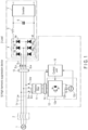
FIG. 1 is a block diagram showing a configuration of each embodiment. -
FIG. 2 is a block diagram showing a configuration of a control unit according to the first embodiment. -
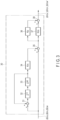
FIG. 3 is a block diagram showing a configuration of a feedback control section inFIG. 2 . -
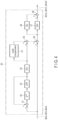
FIG. 4 is a block diagram showing a configuration of a modified example ofFIG. 3 . -
FIG. 5 is a block diagram showing a configuration of a control unit according to the second embodiment. -
FIG. 6 is a chart showing waveforms of an AC voltage, a load current, a system current, and a compensation current of two phases in each embodiment. -
FIG. 7 is a chart showing the waveform of the system current and waveforms of a d-axis component and a q-axis component of the compensation current inFIG. 6 . -
FIG. 8 is a chart showing the waveform of the system current and waveforms of a d-axis component and a q-axis component of the compensation current in prior art as references. - As shown in
FIG. 1 , aload 3 is connected to system lines (power supply lines) Lu, Lv, and Lw of a three-phase AC system (including a three-phase AC power supply, a power system, a distribution system, and the like) 1 via a system impedance 2. - The
load 3 includes a three-phase rectifier circuit 4 that rectifies full waves of the AC voltages (system voltages) Eu, Ev, and Ew of the three-phase AC system 1 by bridge connection ofdiodes 4a to 4f, which are loads having nonlinear characteristics, aDC capacitor 6 connected to an output terminal of the three-phase rectifier circuit 4 via aDC reactor 5, aninverter 7 connected to both ends of theDC capacitor 6, and the like. Theinverter 7 converts the voltage of theDC capacitor 6 into an AC voltage of a predetermined frequency by switching, and outputs the AC voltage as, for example, drive power for a compressor motor of an air conditioner. - A high
harmonic suppression device 10 of the embodiment is connected to a position between the system impedance 2 and theload 3 in the system lines Lu, Lv, and Lw. - The high
harmonic suppression device 10 includes apassive filter 11 for system connection, apower converter 12 connected to the system lines Lu, Lv, and Lw via thepassive filter 11, a detector (first detection section) 13 arranged between the connection position of thepassive filter 11 in the system lines Lu, Lv, and Lw and theload 3 to detect AC voltages Eu, Ev, and Ew of the three-phase AC system 1 and currents (referred to as load currents) ILu, ILv, and ILw flowing to theload 3, a detector (second detection section) 14 arranged in a connection between thepassive filter 11 and thepower converter 12 to detect compensation currents (also referred to as output currents) Icu, Icv, and Icw which are supplied from thepower converter 12 to the system lines Lu, Lv, and Lw, and a control unit (control means) 15 that controls thepower converter 12 in accordance with the detection results of thedetectors - The
passive filter 11 is, for example, an interconnection reactor arranged for each phase of the system lines Lu, Lv, and Lw, or an LCL filter arranged for each phase of the system lines Lu, Lv, and Lw by combining the inductor and the capacitor. - The
power converter 12 is, for example, a three-phase two-level converter, includes aswitching circuit 12a including a plurality of semiconductor switch elements, aDC capacitor 12b connected between both ends of theswitching circuit 12a, and avoltage detector 12c that detects a voltage Vco of theDC capacitor 12b, and generates a three-phase voltage according to a command (request) from thecontrol unit 15 and outputs the voltage to the system lines Lu, Lv, and Lw by switching of theswitching circuit 12a and energization of theDC capacitor 12b accompanying the switching. The high harmonic components contained in the load currents ILu, ILv, and ILw are suppressed by supplying the compensation currents Icu, Icv, and Icw generated by the three-phase voltage from thepower converter 12 to the system lines Lu, Lv, and Lw. - The
control unit 15 detects the high harmonic components contained in the load currents ILu, ILv, and ILw detected by thedetector 13, obtains target values Icu', Icv', and Icw' of the compensation currents Icu, Icv, and Icw, which are to be added to the load currents ILu, ILv, and ILw in order to suppress the high harmonic components, and multiplies the target values Icu', Icv', and Icw' by a gain G based on an impedance Z between the system lines Lu, Lv, and Lw and thepower converter 12, thereby obtains the compensation voltages Vcu, Vcv, and Vcw required to supply the compensation currents Icu, Icv, and Icw of the target values Icu', Icv', and Icw' to the system lines Lu, Lv, and Lw, and cause the compensation voltages Vcu, Vcv, and Vcw to be generated and output by thepower converter 12. - The compensation currents Icu, Icv, and Icw to be added to the load currents ILu, ILv, and ILw in order to suppress the high harmonic components are, specifically, currents to be added to the load currents ILu, ILv, and ILw in order to make the load currents ILu, ILv, and ILw as close to sine waves synchronized with the AC voltages Eu, Ev, and Ew as possible.
- The impedance Z between the system lines Lu, Lv, and Lw and the
power converter 12 is a ratio of the voltage to the current in the electric circuit between the system lines Lu, Lv, and Lw and thepower converter 10, and is determined by the impedance of thepassive filter 11 which exists in the connection between the system lines Lu, Lv, and Lw and thepower converter 12. The impedance of thepassive filter 11 is generally composed of one or more of an interconnection reactor Lac, a filter reactor Lf, a filter capacitor Cf, and a resistor R. - A specific configuration of the
control unit 15 is shown inFIG. 2 . - Values of the load currents ILu, ILv, and ILw detected by the
detector 13 are supplied to a low-pass filter (extraction section) 21 and a calculation unit (first calculation section) 22. The low-pass filter 21 extracts low frequency components of the values of the load currents ILu, ILv, and ILw detected by thedetector 13. Thecalculation unit 22 detects the high harmonic components contained in the load currents ILu, ILv, and ILw by subtracting the low-frequency components extracted by the low-pass filter 21 from the values of the load currents ILu, ILv, and ILw detected by thedetector 13. Then, thecalculation unit 22 calculates target values (command values) Icu', Icv', and Icw' of the compensation currents Icu, Icv, and Icw which are to be added to the load currents ILu, ILv, and ILw in order to suppress the detected high harmonic components. This calculation result is supplied to a differential calculation unit (second calculation section) 23. - The
differential calculation unit 23 calculates the target values Icu', Icv', and Icw' of the compensation voltages Vcu, Vcv, and Vcw necessary to make the compensation voltages Vcu, Vcv, and Vcw of the target values Icu', Icv', and Icw' supplied to the system lines Lu, Lv, and Lw, by holding in advance a predetermined gain G including the impedance Z between the system lines Lu, Lv, and Lw and thepower converter 12, and multiplying the target values Icu', Icv', and Icw' calculated by thecalculation unit 22 by the gain. - The gain G is set based on the impedance Z. More specifically, the gain includes the impedance Z and a time differential term "d/dt" for the target values Icu', Icv', and Icw'. For example, if the impedance Z is the interconnection reactor Lac, a product "Lac × (d/dt)" of the interconnection reactor Lac and the time differential term "d/dt" for the target values Icu', Icv', and Icw' is assumed to be a gain G. In this case, Vcu' = [Lac × (dlcu'/dt)],
- Vcv' = [Lac × (dIcv'/dt)], and
- Vcw' = [Lac × (dIcw'/dt)] are obtained as the target values Vcu', Vcv', and Vcw' of the compensation voltages Vcu, Vcv, and Vcw.
- If the impedance Z is the interconnection reactor Lac and the resistance R of the reactor, "Lac × (d/dt)+R" obtained by adding the resistance R to the product of the interconnection reactor Lac and the time differential term "d/dt" for the target values Icu', Icv', and Icw' is assumed to be the gain G. In this case, Vcu'=[Lac × (dlcu'/dt)+R], Vcv' = [Lac × (dIcv'/dt)+R], and Vcw' = [Lac × (dIcw'/dt)+R] are obtained as the target values Vcu', Vcv', and Vcw' of the compensation voltages Vcu, Vcv, and Vcw.
- In addition, if the passive filter is an LCL filter composed of the interconnection reactor Lac, the filter capacitor Cf, and the filter reactor Lf, product "(Lac+Lf) × (d/dt)+Lac × Lf × Cf × (d^3/dt^3)" using the interconnection reactor Lac, the filter reactor Lf, the differential term "d/dt" for the target values Icu', Icv', and Icw', and a third order differential term "d^3/dt^3" is assumed to be the gain G. However, since the purpose of the filter capacitor Cf is to eliminate a switching ripple component, the third order differential term can be ignored. In this case, Vcu' = [(Lac+Lf) × (dIcu'/dt)], Vcv' = [(Lac+Lf) × (dIcv'/dt)], and Vcw' = [(Lac+Lf) × (dIcw'/dt)] are obtained as the target values Vcu', Vcv', and Vcw' of the compensation voltages Vcu, Vcv, and Vcw.
- Incidentally, when differential calculation is implemented in a digital controller, it is common to combine an appropriate LPF in consideration of the calculation time and implement the differential calculation as an incomplete differential.
- The calculated target values Vcu', Vcv', and Vcw' are supplied to a pulse width modulation circuit (PWM; drive section) 25 via an
addition unit 24. The pulsewidth modulation circuit 25 generates and outputs a plurality of gate signals (on and off signals) for driving theswitching circuit 12a of thepower converter 12 by pulse-width modulating the sinusoidal voltages of the same frequency as the AC voltages Eu, Ev, and Ew detected by thedetector 13 with the target values Vcu', Vcv', and Vcw'. - Each of switching elements of the
switching circuit 12a of thepower converter 12 is turned on and off by these gate signals, and the compensation voltages Vcu, Vcv, and Vcw of the target values Vcu', Vcv', and Vcw' are thereby output from thepower converter 12. According to this output, the compensation currents Icu, Icv, and Icw of target values Icu', Icv', and Icw' flow from thepower converter 12 to the system lines Lu, Lv, and Lw. The high harmonic components contained in the load currents ILu, ILv, and ILw are suppressed by the compensation currents Icu, Icv, and Icw. - Waveforms of the AC voltages Eu and Ev extracted from two phases in the three-
phase AC system 1, waveforms of the load currents ILu and ILv, waveforms of the system currents Iu and Iv in the three-phase AC system 1, and waveforms of the compensation currents Icu and Icv are shown inFIG. 6 . - As described above, the compensation voltages Vcu, Vcv, and Vcw required for the compensation currents Icu, Icv, and Icw of the target values Icu', Icv', and Icw' to be supplied to the system lines Lu, Lv, and Lw can be obtained directly from the target values Icu', Icv', and Icw' by detecting the high harmonic components contained in the load currents ILu, ILv, and ILw, calculating the target values Icu', Icv', and Icw' of the compensation currents Icu, Icv, and Icw to be added to the load currents ILu, ILv, and ILw in order to suppress the high harmonic components, are multiplying the gain G for the target values Icu', Icv', and Icw'. Therefore, the appropriate compensation voltages Vcu, Vcv, and Vcw capable of sufficiently dealing with the high harmonics including high frequency components can be obtained without causing delay or resonance, unlike the conventional device in which gains in proportional/integral calculation need to be increased.
- In other words, in the conventional high harmonic suppression device that obtains the compensation voltage by proportional/integral calculation, the gain of the proportional/integral calculation needs to be increased in order to deal with high harmonics including high frequency components as well, delay and resonance thereby occur, i.e., the control becomes unstable, which rather causes increase in the high harmonics, but high harmonics including high frequency components can be reliably suppressed by directly obtaining the compensation voltages Vcu, Vcv, and Vcw from the target values Icu', Icv', and Icw'.
-
FIG. 7 shows the waveforms of the system currents Iu and Iv in the embodiment in a temporally enlarged manner, and shows one compensation current Icu in the embodiment, as a waveform of a d-axis component and a waveform of a q-axis component whose phase is electrically shifted from the d-axis component by 90 degrees. According to this embodiment, the d-axis component and the q-axis component can be made to appropriately follow the target values, respectively. - In contrast, in the case of the conventional device that obtains the compensation voltage by the proportional/integral calculation, the compensation currents do not appropriately follow the target values and appear as large harmonic noise in the waveforms of the system currents Iu and Iv as shown in
FIG. 8 . Such an inconvenience can be solved in the embodiment. - As shown in
FIG. 2 , in order to deal with unnecessary fluctuations in the AC voltages Eu, Ev, and Ew, the values of the AC voltages Eu, Ev, and Ew detected by thedetector 13 are supplied to theaddition unit 24, and the values of the AC voltages Eu, Ev, and Ew are added to the target values Vcu', Vcv', and Vcw' in theaddition unit 24. The target values Vcu', Vcv', and Vcw' passed through theaddition unit 24 are supplied to the pulsewidth modulation circuit 25. The inconvenience that unnecessary fluctuations in the AC voltages Eu, Ev, and Ew overlap with the compensation voltages Vcu, Vcv, and Vcw can be thereby solved. - In addition, in order to deal with unexpected disturbances to the compensation currents Icu, Icv, and Icw and assumed errors in the impedance Z, and also to keep the voltage Vco of the
DC capacitor 12b in thepower converter 12 constant at a standard value, a calculation unit (third calculation section) 26, a calculation unit (fourth calculation section) 27, avoltage control section 28, and afeedback control section 30 are added to thecontrol unit 15 as shown inFIG. 2 . - The
calculation section 26 obtains deviations (Icu'-Icu), (Icv'-Icv), and (Icw'-Icw) between the target values Icu', Icv', and Icw' calculated by thecalculation section 22 and the actual compensation current values Icu, Icv, and Icw detected by thedetector 14. Thecalculation section 27 obtains a deviation ΔVco between a standard value Vcos predetermined for the voltage Vco of thecapacitor 12b in thepower converter 12 and the actual voltage Vco of thecapacitor 12b detected by thevoltage detector 12c of thepower converter 12. - The
voltage control section 28 obtains a correction value ΔIco that is to be added to the above-described obtained deviations (Icu'-Icu), (Icv'-Icv), and (Icw'-Icw) to constantly maintain the voltage Vco of thecapacitor 12b to the standard value Vcos, by multiplying the deviation ΔVco obtained by thecalculation section 27 by a predetermined voltage control gain. Thecalculation section 26 outputs the deviations ΔIcu, ΔIcv, and ΔIcw obtained by adding the correction value ΔIco to the above-described obtained deviation. - The
feedback control section 30 obtains correction values ΔVcu', ΔVcv', and ΔVcw' that are to be added to the target values Vcu', Vcv', and Vcw' calculated by thedifferentiation calculation section 23, by proportional calculation or proportional/integral calculation using the deviations ΔIcu, ΔIcv, and ΔIcw output from thecalculation section 26 as inputs, such that the deviations ΔIcu, ΔIcv, and ΔIcw obtained by thecalculation section 26 become zero. The obtained correction values ΔVcu', ΔVcv', and ΔVcw' are added to the target values Vcu', Vcv', and Vcw' in theaddition section 24. As a result, stable and appropriate compensation voltages Vcu, Vcv, and Vcw that can constantly maintain the voltage Vco of thecapacitor 12b in thepower converter 12 at the standard value can be obtained without being greatly affected by unexpected disturbances to the compensation currents Icu, Icv, and Icw or assumed errors in the impedance Z. - As shown in
FIG. 3 , for example, thefeedback control section 30 sums while holding and integrating the deviations ΔIcu, ΔIcv, and ΔIcw supplied from thecalculation section 26 for each cycle by a loop configuration of anaddition section 31, a holdingsection 32, and an integrating section (LPF) 33, multiplies the summation result by a predetermined loop gain Krc for loop control by a multiplyingsection 34, and adds the multiplication result to the deviations ΔIcu, ΔIcv, and ΔIcw supplied from thecalculation section 26, in anaddition section 35. Then, thefeedback control section 30 multiplies the deviations ΔIcu, ΔIcv, and ΔIcw that have passed through theaddition section 35 by a proportional gain Kp in aproportional calculation section 36, and simultaneously multiplies the deviations by an integral gain Ki/s in theintegral calculation section 37, and adds the multiplication results by anaddition section 38 to obtain the correction values ΔVcu', ΔVcv', and ΔVcw' that are to be added to the target values Vcu', Vcv', and Vcw' calculated by thedifferential calculation section 23 such that the deviations ΔIcu, ΔIcv, and ΔIcw obtained in thecalculation section 26 become zero. - The unit sums while holding and integrating the deviations ΔIcu, ΔIcv, and ΔIcw for each cycle of the AC voltages Eu, Ev and Ew, multiplies the summation result by the loop gain Krc, and thereby reduces periodic errors in the deviations ΔIcu, ΔIcv, and ΔIcw.
- The
feedback control section 30 may be configured to multiply the multiplication result obtained by the loop configuration of theaddition section 31, the holdingsection 32, and the integration section (LPF) 33 by the loop gain Krc in themultiplication section 34 and to add a lead compensation process of the loop configuration of alead compensator 41 and anaddition section 42 to the multiplication result, as shown inFIG. 4 . By adding the lead compensation process, it is possible to compensate for the delay time of the process due to the proportional/integral calculation of theproportional calculation section 36 and theintegral calculation section 37. - A band elimination filter (first band elimination section) 51 and a holding
unit 52 are sequentially arranged on a signal path from acalculation section 22 for calculating target values Icu', Icv', and Icw' to adifferential calculation section 23 for calculating the target values Icu', Icv', and Icw'. Furthermore, a band elimination filter (second band elimination section) 52 is arranged on a signal path from adetector 14 for detecting values of compensation currents Icu, Icv, and Icw to acalculation section 26 for obtaining deviations ΔIcu, ΔIcv, and ΔIcw. - When a
passive filter 11 on the output side of apower converter 12 is an LCL filter, theband elimination filter 51 eliminates a predetermined frequency band of the target values Icu', Icv', and Icw' calculated in thecalculation section 22 to avoid resonance in the LCL filter. When resonance occurs in the LCL filter, unintended high harmonic components may overlap with the compensation currents Icu, Icv, and Icw output from thepower converter 12 and, therefore, the resonance is avoided by the band elimination process for the target values Icu', Icv', and Icw'. - The holding
section 52 temporarily holds the target values Icu', Icv', and Icw' that have passed through theband elimination filter 51 in one cycle of AC voltages Eu, Ev, and Ew in order to compensate for deviations between the target values Icu', Icv', and Icw' and the actual compensation currents Icu, Icv, and Icw due to control delay and detection delay. - The
band elimination filter 52 is, for example, a notch filter, and eliminates a predetermined frequency band of the compensation currents Icu, Icv, and Icw detected by thedetector 14 in order to solve an inconvenience that high harmonic components resulting from employment of afeedback control section 30 are made to overlap with the compensation currents Icu, Icv, and Icw detected by thedetector 14 and to solve an inconvenience that the high harmonic components are amplified by the gain of thefeedback control section 30. - In each of the above embodiments, a three-phase two-level converter is used as the
power converter 12, but is not limited and a multi-level converter may be used. - The control of the
control unit 15 may be configured to be divided into control of the d-axis component having the same phase as the AC voltages Eu, Ev, and Ew, and control of the q-axis component whose phase is electrically shifted from the d-axis component by 90 degrees, by rotational coordinate transformation based on the phases of the AC voltages Eu, Ev, and Ew. Interference terms between the phases and between the d-axis and the q-axis in thepower converter 12 can be thereby eliminated. If the load currents ILu, ILv, and ILw are subjected to rotational coordinate transformation, the target values Icu', Icv', and Icw' of the load currents ILu, ILv, and ILw can be obtained by extracting only the DC amount from the load currents ILu, ILv, and ILw containing the high harmonic components and by subtracting it from the original load currents ILu, ILv, and ILw. - While certain embodiments and modification examples have been described, they have been presented by way of example only, and are not intended to limit the scope of the inventions. Indeed, these embodiments described herein may be embodied in a variety of other forms; furthermore, various omissions, substitutions and changes in the form of the embodiment described herein may be made without departing from the spirit of the invention. The accompanying claims and their equivalents are intended to cover such forms or modifications as would fall within the scope and spirit of the inventions.
- 1 ... System power supply, 2 ... Load, Lu, Lv, and Lw ... System lines, 10 ... High harmonic suppression device, 11 ... Passive filter, 12 ... Power converter, 12a ... Switching circuit, 12b ... Capacitor, 12c ... Voltage detector, 13 and 14 ... Detectors, 15 ... Control unit, 21 ... Low-pass filter (extraction section), 22 ... Calculation unit (first calculation section), 23 ... Differential calculation unit (second calculation section), and 25 ... Pulse width modulation circuit (drive section).
Claims (12)
- A high harmonic suppression device, comprising:a power converter connected to a system line between an AC system and a load to generate and output an AC voltage to the system line; andcontrol unit configured to detect a high harmonic component of a load current flowing in the system line, obtain a target value of a compensation current to be added to the load current in order to suppress the high harmonic component, and multiply the target value by a gain based on an impedance between the system line and the power converter, thereby obtain a compensation voltage necessary to supply the compensation current of the target value to the system line and cause the compensation voltage to be generated and output by the power converter.
- The high harmonic suppression device of claim 1, wherein
the gain includes the impedance and also includes a time differential term for the target value. - The high harmonic suppression device of claim 1, further comprising:
a passive filter for system connection, which is provided in a connection between the system line and the power converter. - The high harmonic suppression device of claim 1, wherein
the control unit includes:first detection section configured to detect the load current;extraction section configured to extract a low frequency component of the load current detected by the first detection section;first calculation section configured to detect the high harmonic component included in the load current by subtracting a low frequency component extracted by the extraction section from the load current detected by the first detection section, and calculate a target value of the compensation current to be added to the load current in order to suppress the high harmonic component;second calculation section configured to multiply the target value calculated by the first calculation section by a gain including an impedance between the system line and the power converter and a time differential term for the target value, and thereby calculate a target value of a compensation voltage necessary to supply the compensation current of the target value calculated by the first calculation section to the system line; anddrive section configured to drive the power converter in accordance with the target value calculated by the second calculation section, and thereby cause the compensation voltage of the target value to be generated and output by the power converter. - The high harmonic suppression device of claim 4, whereinwhen the impedance is an interconnection reactor Lac, the gain is a product "Lac × (d/dt)" of the interconnection reactor Lac and a time differential term "d/dt" for the target values Icu', Icv', and Icw',when the impedance is the interconnection reactor Lac and a resistance R, the gain is "Lac × (d/dt)+R" obtained by adding the resistance R to the product of the interconnection reactor Lac and the time differential term "d/dt", andwhen the impedance is an LCL filter composed of the interconnection reactor Lac, a filter capacitor Cf, and a filter reactor Lf, the gain is a product "(Lac+Lf) × (d/dt)" of the interconnection reactor Lac, the filter reactor Lf, and the time differential term "d/dt".
- The high harmonic suppression device of claim 3, wherein
the control unit further includes:second detection section configured to detect the compensation current supplied from the power converter to the system line;third calculation section configured to obtain a deviation between the target value calculated by the first calculation section and a value of the compensation current detected by the second calculation section;feedback control section configured to obtain the correction value to be added to the target value calculated by the second calculation section by proportional calculation or proportional/integral calculation using the deviation obtained by the third calculation section as an input, such that the deviation obtained by the third calculation section becomes zero; andaddition section configured to add the correction value obtained by the feedback control section to the target value calculated by the second calculation section. - The high harmonic suppression device of claim 6, wherein
the feedback control section sums while holding and integrating the deviation obtained by the third calculation section in each cycle of an AC voltage of the AC system, multiplies the multiplication result by a predetermined loop gain, adds the multiplication result to the deviation obtained by the third calculation section, and obtains a correction value to be added to the target value calculated by the second calculation section by proportional calculation or proportional/integral calculation using the addition result as an input such that the deviation obtained by the third calculation section becomes zero. - The high harmonic suppression device of claim 7, wherein
the feedback control section adds a lead compensation process for compensating for a delay time of process using the proportional calculation or the proportional/integral calculation to the multiplication result of the loop gain. - The high harmonic suppression device of claim 4, whereinthe control unit further includes first band elimination section configured to eliminate a predetermined frequency band of the target value calculated by the first calculation section, andthe second calculation section calculates a target value of a compensation voltage necessary to supply the compensation current of the target value calculated by the first calculation section to the system line, by multiplying the target value which has passed through the first band elimination section by the gain.
- The high harmonic suppression device of claim 4, whereinthe control section further includes holding section for temporarily holding the target value calculated by the first calculation section in a cycle of the AC voltage of the AC system, andthe second calculation section calculates target values Vcu', Vcv', and Vcw' of compensation voltages Vcu, Vcv, and Vcw necessary to supply the compensation current of the target value calculated by the first calculation section to the system line, by multiplying the target value held by the holding section by the gain.
- The high harmonic suppression device of claim 6, whereinthe control section further includes second band elimination section for eliminating a predetermined frequency band of values of compensation currents Icu, Icv, and Icw detected by the second detection section, andthe third calculation section obtains deviations ΔIcu, ΔIcv, and ΔIcw between the target values Icu', Icv', and Icw' calculated by the first calculation section and compensation currents Icu, Icv, and Icw which have passed through a process of the second band elimination section.
- The high harmonic suppression device of one of claims 1 to 9, wherein
the load includes a diode-bridge rectifier circuit which rectifies a voltage of the AC power, a DC capacitor connected to an output terminal of the rectifier circuit via a DC reactor, and an inverter which converts a voltage of the DC capacitor into an AC voltage of a predetermined frequency.
Applications Claiming Priority (2)
| Application Number | Priority Date | Filing Date | Title |
|---|---|---|---|
| JP2021105347 | 2021-06-25 | ||
| PCT/JP2022/024555 WO2022270470A1 (en) | 2021-06-25 | 2022-06-20 | High harmonic suppression device |
Publications (2)
| Publication Number | Publication Date |
|---|---|
| EP4362308A1 true EP4362308A1 (en) | 2024-05-01 |
| EP4362308A4 EP4362308A4 (en) | 2025-06-11 |
Family
ID=84545701
Family Applications (1)
| Application Number | Title | Priority Date | Filing Date |
|---|---|---|---|
| EP22828387.5A Pending EP4362308A4 (en) | 2021-06-25 | 2022-06-20 | DEVICE FOR SUPPRESSING HIGH HARMONICS |
Country Status (3)
| Country | Link |
|---|---|
| EP (1) | EP4362308A4 (en) |
| JP (1) | JP7604648B2 (en) |
| WO (1) | WO2022270470A1 (en) |
Family Cites Families (6)
| Publication number | Priority date | Publication date | Assignee | Title |
|---|---|---|---|---|
| JPH0691711B2 (en) | 1988-03-04 | 1994-11-14 | 三菱電機株式会社 | Active filter device |
| US6775157B2 (en) * | 2002-06-25 | 2004-08-10 | International Rectifier Corporation | Closed loop active EMI filter for reducing common or differential noise based on an error value |
| JP5253523B2 (en) * | 2011-01-04 | 2013-07-31 | 三菱電機株式会社 | Harmonic current compensator |
| JP5713044B2 (en) | 2013-04-15 | 2015-05-07 | ダイキン工業株式会社 | Control device |
| JP5850117B2 (en) | 2013-09-30 | 2016-02-03 | ダイキン工業株式会社 | Power converter |
| JP6605419B2 (en) | 2016-09-02 | 2019-11-13 | 株式会社神戸製鋼所 | Active filter |
-
2022
- 2022-06-20 EP EP22828387.5A patent/EP4362308A4/en active Pending
- 2022-06-20 JP JP2023530464A patent/JP7604648B2/en active Active
- 2022-06-20 WO PCT/JP2022/024555 patent/WO2022270470A1/en not_active Ceased
Also Published As
| Publication number | Publication date |
|---|---|
| JPWO2022270470A1 (en) | 2022-12-29 |
| JP7604648B2 (en) | 2024-12-23 |
| EP4362308A4 (en) | 2025-06-11 |
| WO2022270470A1 (en) | 2022-12-29 |
Similar Documents
| Publication | Publication Date | Title |
|---|---|---|
| US9509229B2 (en) | Power supply apparatus including power conversion circuit controlled by PWM control circuit | |
| EP2020740B1 (en) | Power converter | |
| US10511220B2 (en) | Control device for active filter | |
| EP1921740B1 (en) | Power converter control | |
| CN105529947B (en) | Neutral-point-clamped type power inverter and its control method | |
| JP5192258B2 (en) | Clamp type power converter | |
| US20230051706A1 (en) | Power conversion device | |
| US11218079B2 (en) | Power conversion device | |
| EP2988414B1 (en) | Control device | |
| JP5622437B2 (en) | Neutral point clamp type power converter | |
| US20220166307A1 (en) | Electrical circuits for power factor correction by measurement and removal of overtones and power factor maximization | |
| KR20130078380A (en) | Control apparatus for regenerative medium voltage inverter | |
| JP2016158323A (en) | Harmonic restraint device with active filter | |
| EP3093976A1 (en) | Electric power conversion system | |
| JPWO2019097605A1 (en) | Power conversion system | |
| JP5787053B2 (en) | Control device for three-phase V-connection converter | |
| US10756646B2 (en) | Multi-level inverter control device and control method | |
| JP5833524B2 (en) | Power converter and control device for power converter | |
| JP7604648B2 (en) | Harmonic suppression device | |
| JP2023107489A (en) | Harmonic suppression system | |
| US20220393569A1 (en) | Controller of power conversion device | |
| JP7786353B2 (en) | Neutral point potential control device and neutral point potential control method for three-level inverter | |
| JP7802137B2 (en) | Power Conversion Device | |
| JP2012143081A (en) | Control device of three-phase v-connection type inverter | |
| JPH0731156A (en) | Three-phase inverter control device |
Legal Events
| Date | Code | Title | Description |
|---|---|---|---|
| STAA | Information on the status of an ep patent application or granted ep patent |
Free format text: STATUS: THE INTERNATIONAL PUBLICATION HAS BEEN MADE |
|
| PUAI | Public reference made under article 153(3) epc to a published international application that has entered the european phase |
Free format text: ORIGINAL CODE: 0009012 |
|
| STAA | Information on the status of an ep patent application or granted ep patent |
Free format text: STATUS: REQUEST FOR EXAMINATION WAS MADE |
|
| 17P | Request for examination filed |
Effective date: 20231204 |
|
| AK | Designated contracting states |
Kind code of ref document: A1 Designated state(s): AL AT BE BG CH CY CZ DE DK EE ES FI FR GB GR HR HU IE IS IT LI LT LU LV MC MK MT NL NO PL PT RO RS SE SI SK SM TR |
|
| DAV | Request for validation of the european patent (deleted) | ||
| DAX | Request for extension of the european patent (deleted) | ||
| REG | Reference to a national code |
Ref country code: DE Ref legal event code: R079 Free format text: PREVIOUS MAIN CLASS: H02M0007480000 Ipc: H02M0001120000 |
|
| A4 | Supplementary search report drawn up and despatched |
Effective date: 20250509 |
|
| RIC1 | Information provided on ipc code assigned before grant |
Ipc: H02J 3/18 20060101ALN20250505BHEP Ipc: H02J 3/01 20060101ALN20250505BHEP Ipc: H02M 1/42 20070101ALN20250505BHEP Ipc: H02M 7/48 20070101ALI20250505BHEP Ipc: H02M 1/12 20060101AFI20250505BHEP |