EP4362055A2 - Electron microscope, multipole element for use therein, and control method for such electron microscope - Google Patents
Electron microscope, multipole element for use therein, and control method for such electron microscope Download PDFInfo
- Publication number
- EP4362055A2 EP4362055A2 EP23197630.9A EP23197630A EP4362055A2 EP 4362055 A2 EP4362055 A2 EP 4362055A2 EP 23197630 A EP23197630 A EP 23197630A EP 4362055 A2 EP4362055 A2 EP 4362055A2
- Authority
- EP
- European Patent Office
- Prior art keywords
- coil
- mode
- multipolar
- electron
- magnetic
- Prior art date
- Legal status (The legal status is an assumption and is not a legal conclusion. Google has not performed a legal analysis and makes no representation as to the accuracy of the status listed.)
- Pending
Links
- 230000005405 multipole Effects 0.000 title claims abstract description 164
- 238000000034 method Methods 0.000 title claims description 19
- 230000003287 optical effect Effects 0.000 claims abstract description 134
- 230000004075 alteration Effects 0.000 claims abstract description 131
- 230000005291 magnetic effect Effects 0.000 claims abstract description 118
- 238000005286 illumination Methods 0.000 claims description 28
- 238000010894 electron beam technology Methods 0.000 claims description 25
- 238000003384 imaging method Methods 0.000 claims description 14
- 230000001678 irradiating effect Effects 0.000 claims description 2
- 239000000523 sample Substances 0.000 description 36
- 238000012986 modification Methods 0.000 description 13
- 230000004048 modification Effects 0.000 description 13
- 238000010586 diagram Methods 0.000 description 12
- 230000004913 activation Effects 0.000 description 8
- 230000009849 deactivation Effects 0.000 description 8
- 238000012545 processing Methods 0.000 description 8
- 230000005540 biological transmission Effects 0.000 description 7
- 230000005672 electromagnetic field Effects 0.000 description 7
- 201000009310 astigmatism Diseases 0.000 description 6
- 238000000851 scanning transmission electron micrograph Methods 0.000 description 5
- 238000001514 detection method Methods 0.000 description 4
- 238000012546 transfer Methods 0.000 description 4
- 230000006870 function Effects 0.000 description 3
- XEEYBQQBJWHFJM-UHFFFAOYSA-N Iron Chemical compound [Fe] XEEYBQQBJWHFJM-UHFFFAOYSA-N 0.000 description 2
- 230000009471 action Effects 0.000 description 2
- 238000012937 correction Methods 0.000 description 2
- 230000002542 deteriorative effect Effects 0.000 description 2
- 238000004458 analytical method Methods 0.000 description 1
- 239000000470 constituent Substances 0.000 description 1
- 238000013461 design Methods 0.000 description 1
- 230000000694 effects Effects 0.000 description 1
- 230000005284 excitation Effects 0.000 description 1
- 239000003302 ferromagnetic material Substances 0.000 description 1
- 230000002401 inhibitory effect Effects 0.000 description 1
- 229910052742 iron Inorganic materials 0.000 description 1
- 239000000696 magnetic material Substances 0.000 description 1
- 239000013307 optical fiber Substances 0.000 description 1
- 230000000717 retained effect Effects 0.000 description 1
- 239000004065 semiconductor Substances 0.000 description 1
- 238000012800 visualization Methods 0.000 description 1
Images





Classifications
-
- H—ELECTRICITY
- H01—ELECTRIC ELEMENTS
- H01J—ELECTRIC DISCHARGE TUBES OR DISCHARGE LAMPS
- H01J37/00—Discharge tubes with provision for introducing objects or material to be exposed to the discharge, e.g. for the purpose of examination or processing thereof
- H01J37/02—Details
- H01J37/04—Arrangements of electrodes and associated parts for generating or controlling the discharge, e.g. electron-optical arrangement or ion-optical arrangement
- H01J37/153—Electron-optical or ion-optical arrangements for the correction of image defects, e.g. stigmators
-
- H—ELECTRICITY
- H01—ELECTRIC ELEMENTS
- H01F—MAGNETS; INDUCTANCES; TRANSFORMERS; SELECTION OF MATERIALS FOR THEIR MAGNETIC PROPERTIES
- H01F7/00—Magnets
- H01F7/06—Electromagnets; Actuators including electromagnets
- H01F7/20—Electromagnets; Actuators including electromagnets without armatures
-
- H—ELECTRICITY
- H01—ELECTRIC ELEMENTS
- H01J—ELECTRIC DISCHARGE TUBES OR DISCHARGE LAMPS
- H01J37/00—Discharge tubes with provision for introducing objects or material to be exposed to the discharge, e.g. for the purpose of examination or processing thereof
- H01J37/02—Details
- H01J37/04—Arrangements of electrodes and associated parts for generating or controlling the discharge, e.g. electron-optical arrangement or ion-optical arrangement
- H01J37/10—Lenses
- H01J37/14—Lenses magnetic
- H01J37/141—Electromagnetic lenses
-
- H—ELECTRICITY
- H01—ELECTRIC ELEMENTS
- H01J—ELECTRIC DISCHARGE TUBES OR DISCHARGE LAMPS
- H01J37/00—Discharge tubes with provision for introducing objects or material to be exposed to the discharge, e.g. for the purpose of examination or processing thereof
- H01J37/26—Electron or ion microscopes; Electron or ion diffraction tubes
-
- H—ELECTRICITY
- H01—ELECTRIC ELEMENTS
- H01J—ELECTRIC DISCHARGE TUBES OR DISCHARGE LAMPS
- H01J37/00—Discharge tubes with provision for introducing objects or material to be exposed to the discharge, e.g. for the purpose of examination or processing thereof
- H01J37/26—Electron or ion microscopes; Electron or ion diffraction tubes
- H01J37/28—Electron or ion microscopes; Electron or ion diffraction tubes with scanning beams
-
- H—ELECTRICITY
- H01—ELECTRIC ELEMENTS
- H01J—ELECTRIC DISCHARGE TUBES OR DISCHARGE LAMPS
- H01J2237/00—Discharge tubes exposing object to beam, e.g. for analysis treatment, etching, imaging
- H01J2237/153—Correcting image defects, e.g. stigmators
-
- H—ELECTRICITY
- H01—ELECTRIC ELEMENTS
- H01J—ELECTRIC DISCHARGE TUBES OR DISCHARGE LAMPS
- H01J2237/00—Discharge tubes exposing object to beam, e.g. for analysis treatment, etching, imaging
- H01J2237/153—Correcting image defects, e.g. stigmators
- H01J2237/1534—Aberrations
-
- H—ELECTRICITY
- H01—ELECTRIC ELEMENTS
- H01J—ELECTRIC DISCHARGE TUBES OR DISCHARGE LAMPS
- H01J2237/00—Discharge tubes exposing object to beam, e.g. for analysis treatment, etching, imaging
- H01J2237/26—Electron or ion microscopes
- H01J2237/28—Scanning microscopes
- H01J2237/2802—Transmission microscopes
Definitions
- the present invention relates to an electron microscope and a control method therefor.
- the invention also relates to a multipole element used in such an electron microscope.
- aberration correction is an important technique in acquiring high-resolution images.
- TEM transmission electron microscope
- STEM scanning transmission electron microscope
- SEM scanning electron microscope
- patent document 1 discloses a two-stage hexapole field type spherical aberration corrector having two stages of hexapole elements each of which produces a hexapole field.
- this spherical aberration corrector positive spherical aberration in an objective lens is corrected by negative spherical aberrations produced respectively by the two stages of hexapole elements.
- a multipole element has a plurality of magnetic polepieces each of which includes a magnetic core and a coil wound around the core.
- the multipole element is made to produce a multipolar field by supplying an energization current to the coil.
- the electron optical system is operated in various modes according to purposes. For example, in a mode of operation for acquiring a high-resolution STEM image, aberrations in the illumination optics are corrected by an aberration corrector.
- a differential phase contrast (DPC) method the amount of deflection of an electron beam caused by the electromagnetic field within a sample is measured and the electromagnetic field is visualized.
- a diffraction imaging method a sample image is reconstructed from a diffraction pattern of the sample.
- an optical mode in which a small angle of convergence can be achieved. In this mode, aberrations are not corrected by the aberration corrector for the following reason. In an optical system where small angles of convergence occur, if a multipolar field is produced, large amounts of undesired aberrations arise, thus deteriorating the resolution.
- Patent document 1 JP-A-2003-92078
- each multipole element of the aberration corrector is switched from an inoperative mode in which no multipolar field is produced to an operative mode in which a multipolar field is produced. Consequently, energization currents flow through the coils, thus bringing about great variations in the temperatures of the multipole elements. This in turn varies aberrations arising from the aberration corrector. Hence, it has been impossible to perform an observation or analysis from when the optical mode is switched until fluctuations of aberrations settle down.
- One aspect of the electron microscope associated with the present invention comprises an electron optical system having a built-in aberration corrector equipped with multipole elements each for producing a multipolar field.
- Each of the multipole elements includes a plurality of magnetic polepieces.
- Each of the magnetic polepieces includes a magnetic core, a first coil wound around the core, and a second coil wound around the core. The first and second coils produce a first multipolar field and a second multipolar field, respectively, when energized.
- the first and second multipolar fields are identical in terms of symmetry.
- the first and second multipolar fields can be made to cancel out each other by orienting the first and second multipolar fields in opposite senses. Therefore, activation and deactivation of the multipolar field from each multipole element can be controlled by varying the sense of the magnetic field produced by the second or first coil. Consequently, the amount of heat of the multipole element in the presence of the multipolar field can be made equal to the amount of heat of the multipole element in the absence of the multipolar field.
- One aspect of the multipole element associated with the present invention comprises a plurality of magnetic polepieces for producing a multipolar field.
- Each of the magnetic polepieces includes a magnetic core, a first coil wound around the core, and a second coil wound around the core.
- the first and second coils produce a first multipolar field and a second multipolar field, respectively, when energized.
- the first and second multipolar fields are identical in terms of symmetry.
- the first and second multipolar fields can be made to cancel out each other by orienting the first and second multipolar fields in opposite senses. Therefore, activation and deactivation of the multipolar field from each multipole element can be controlled by varying the sense of the magnetic field produced by the second or first coil. Consequently, with this multipole element, the amount of heat generated when the multipolar field is activated can be made equal to the amount of heat generated when the multipolar field is deactivated.
- One aspect of the control method associated with the present invention is for use in controlling an electron microscope comprising an electron optical system having a built-in aberration corrector equipped with multipole elements each for producing a multipolar field.
- the control method comprises the steps of: operating the electron optical system in a first optical mode in which aberrations are not corrected by the aberration corrector; and making a switch from the first optical mode to a second optical mode in which aberrations are corrected by the aberration corrector and operating the electron optical system.
- Each of the multipole elements includes a plurality of magnetic polepieces.
- Each of the magnetic polepieces includes a magnetic core, a first coil wound around the core, and a second coil wound around the core.
- the first and second coils produce a first multipolar field and a second multipolar field, respectively, when energized.
- the first and second multipolar fields are identical in terms of symmetry.
- Each of the multipole elements has an inoperative mode and an operative mode. In the inoperative mode, no multipolar field is produced by causing the magnetic fields generated by the first and second coils, respectively, to be oriented in opposite senses. In the operative mode, a multipolar field is produced by causing the magnetic fields respectively produced by the first and second coils to be oriented in the same sense. In the step of making a switch from the first optical mode to the second optical mode, the multipole element is switched from the inoperative mode to the operative mode.
- This control method for the electron microscope involves the step of making a switch from the first optical mode to the second optical mode.
- the multipole element is switched from the inoperative mode, in which no multipolar field is produced from the multipole element by causing the magnetic fields respectively generated by the first and second coils to be oriented in opposite senses, to the operative mode, in which the magnetic fields respectively generated by the first and second coils are oriented in the same sense such that a multipolar field is produced from the multipole element. Consequently, there occur less aberration variations when a switch is made from the first to the second optical mode.
- FIG. 1 shows the configuration of the electron microscope, 100.
- the electron microscope 100 includes an electron source 10, an electron optical system 2, a sample stage 30, an STEM detector 50, a segmented detector 52, and a controller 60.
- the electron optical system 2 includes illumination optics 20 and imaging optics 40.
- the electron microscope 100 is a scanning transmission electron microscope (STEM) having an aberration corrector 26 incorporated in the illumination optics 20.
- the electron source 10 which emits an electron beam is an electron gun, for example, that emits the electron beam by accelerating electrons with an anode after the electrons are released from a cathode.
- the electron optical system 2 includes the illumination optics 20 and the imaging optics 40 as mentioned above.
- the electron beam emitted from the electron source 10 is directed at a sample S through the illumination optics 20 which, for example, focuses the electron beam from the electron source 10 into an electron probe that scans the sample S.
- the imaging optics 40 images the electrons transmitted through the sample S.
- the electron beam transmitted through the sample S is passed onto the STEM detector 50 and onto the segmented detector 52 via the imaging optics 40.
- the STEM detector 50 detects electrons transmitted through the sample S.
- the STEM detector 50 is a dark-field STEM detector using an annular detector for detecting electrons inelastically scattered through high angles from the sample S.
- the segmented detector 52 has an electron sensitive surface 53 for detecting the electrons transmitted through the sample S, the sensitive surface 53 being split into a plurality of detector segments.
- FIG. 2 schematically shows the sensitive surface 53 of the segmented detector 52.
- the sensitive surface 53 is divided into detector segments D1, D2, D3, and D4 which are formed by angularly (circumferentially) quartering the annular sensitive surface 53 of the segmented detector 52.
- Each of the four detector segments D1-D4 can independently detect electrons.
- the segmented detector 52 may have a plurality of detector segments which are separated from each other radially and circumferentially in a manner not illustrated.
- the sensitive surface 53 of the segmented detector 52 may have 16 detector segments by being radially divided by 4 and circumferentially divided by 4.
- the segmented detector 52 includes, for example, an electron-to-light converter (scintillator) for converting electrons into light, light transmission paths (consisting of a bundle of optical fibers) for separating the electron-to-light converter into the detector segments D1, D2, D3, and D4 and transmitting light signals from the detector segments D1-D4, and a plurality of optical detectors (photoelectron multipliers) for producing detection signals responsive to the electron intensities respectively detected by the detector segments D1-D4.
- the segmented detector 52 may be a semiconductor detector having a plurality of detector segments.
- the sample stage 30 mechanically supports the sample S held to a sample holder 32 and permits the sample S to be placed in position.
- the controller 60 includes a processor (such as a CPU (central processing unit)) and storage devices (such as a RAM (random access memory) and a ROM (read-only memory)). Programs and data for carrying out various control operations are stored in the storage devices. The functions of the controller 60 can be implemented by executing programs by means of the processor. The controller 60 controls various parts of the electron microscope 100 via driver circuitry (not shown).
- a processor such as a CPU (central processing unit)
- storage devices such as a RAM (random access memory) and a ROM (read-only memory)
- Programs and data for carrying out various control operations are stored in the storage devices.
- the functions of the controller 60 can be implemented by executing programs by means of the processor.
- the controller 60 controls various parts of the electron microscope 100 via driver circuitry (not shown).
- FIG. 3 illustrates the configuration of the illumination optics 20.
- the illumination optics 20 includes a first condenser lens 21, a second condenser lens 22, a condenser aperture 23, a third condenser lens 24, the above-described aberration corrector 26, and a condenser minilens 28.
- the illumination optics 20 further includes a front magnetic field 29 produced in front of the sample S by the objective lens.
- the first condenser lens 21, second condenser lens 22, and third condenser lens 24 are arranged in this order from a side of the electron source 10. These three condenser lenses 21, 22, and 24 together converge an electron beam.
- the condenser aperture 23 is placed within the second condenser lens 22.
- the aberration corrector 26 is disposed between the third condenser lens 24 and the condenser minilens 28.
- the aberration corrector 26 is incorporated in the illumination optics 20, and is a spherical aberration corrector for correcting spherical aberration in the illumination optics 20.
- the aberration corrector 26 includes two stages of multipole elements 260, a first collector lens 262, a second collector lens 264, a third collector lens 266, and a fourth collector lens 268.
- the aberration corrector 26 is a two-stage hexapole spherical aberration corrector having the two stages of multipole elements 260.
- Each multipole element 260 produces a hexapolar magnetic field of three-fold symmetry.
- each multipole element 260 is a hexapole element, a dodecapole element, or any other multipole element capable of generating a hexapolar magnetic field.
- the first collector lens 262, second collector lens 264, and third collector lens 266 are placed between the first stage of multipole element 260 and the second stage of multipole element 260. These three collector lenses 262, 264, and 266 together constitute transfer optics for transferring the principal optical plane of the first stage of multipole element 260 to the principal optical plane of the second stage of multipole element 260. This transfer optics transfers an image equivalent to the output image of the first stage of multipole element 260 to the second stage of multipole element 260.
- the second collector lens 264 is positioned between the first collector lens 262 and the third collector lens 266. The second collector lens 264 imparts a rotary action to the electron beam without applying a light focusing action to the beam.
- the fourth collector lens 268 is disposed between the second stage of multipole element 260 and the condenser minilens 28 and serves as a transfer lens.
- Each multipole element 260 has a thickness in the direction of travel of the electron beam, i.e., along the optical axis OA. That is, the multipole element 260 produces a negative spherical aberration as a combination aberration of three-fold astigmatisms in a hexapolar field having a thickness.
- the combination aberration referred to herein is a combination of aberrations 1 and 2 when the aberration 1 occurs at some location, propagates a distance, thereby varies the point of incidence, and is affected by the other aberration 2.
- Positive spherical aberration in the illumination optics 20 can be corrected by negative spherical aberrations respectively produced by the first stage of multipole element 260 and the second stage of multipole element 260.
- the three-fold astigmatism produced by the second stage of multipole element 260 is opposite in sense to the three-fold astigmatism produced by the first stage of multipole element 260. Therefore, the three-fold astigmatism produced by the first stage of multipole element 260 can be canceled out by the three-fold astigmatism produced by the second stage of multipole element 260.
- the aberration corrector 26 may also be of the three-stage, hexapolar field type.
- the condenser minilens 28 is located between the aberration corrector 26 and the magnetic field 29 produced forwardly of the objective lens, and is operative to create an electron beam having a convergence angle adapted for the optical mode.
- the convergence angle can be varied by varying the excitation of the condenser minilens 28.
- the magnetic field 29 produced forwardly of the objective lens functions as a condenser lens for converging an electron beam.
- the illumination optics 20 includes a scan deflector (not shown) for deflecting the electron beam in two dimensions.
- the scan deflector permits the sample S to be scanned with the electron beam.
- FIG. 4 schematically shows the configuration of each multipole element 260. It is herein assumed that the multipole element 260 has six magnetic polepieces. The number of the magnetic polepieces of the multipole element 260 can be appropriately varied according to the symmetry of the generated magnetic fields.
- the multipole element 260 has the six magnetic polepieces 4 which are disposed radially with respect to an optical axis OA.
- a hexapolar field of three-fold symmetry is produced by imparting alternately opposite polarities to the magnetic polepieces 4.
- Each magnetic polepiece 4 includes a magnetic core 6, a first coil 8a, and a second coil 8b.
- the magnetic core 6 is a metallic rodlike member as made of a soft magnetic material.
- Each of the six magnetic cores 6 making up the multipole element 260 is wrapped with the first coil 8a and the second coil 8b. Therefore, the multipolar field created by the multipole element 260 by energization of the first coil 8a and the multipolar field created by the multipole element 260 by energization of the second coil 8b have the same symmetry.
- the multipolar field created by the multipole element 260 by energization of the first coil 8a is a hexapolar field of three-fold symmetry.
- the multipolar field created by the multipole element 260 by energization of the second coil 8b is a hexapolar field of three-fold symmetry.
- FIG. 5 schematically illustrates one magnetic polepiece 4.
- the first coil 8a is wound on the magnetic core 6.
- the second coil 8b is also wound on the magnetic core 6.
- the first coil 8a is disposed near the rear end of the magnetic polepiece 4, while the second coil 8b is disposed near the front end of the polepiece 4.
- the first coil 8a and the second coil 8b may be located near the front end and the rear end, respectively, of the magnetic polepiece 4 in a manner not illustrated.
- the first coil 8a and the second coil 8b are supplied with energization currents from a power supply 9.
- the power supply 9 supplies the energization currents, which can be different in polarity or sense, for example, to the first coil 8a and the second coil 8b. Furthermore, the power supply 9 can supply different amounts of energization current to the first coil 8a and the second coil 8b.
- the power supply 9 is under control of the controller 60.
- the first coil 8a and the second coil 8b are wound in the same sense. Therefore, by energizing the first coil 8a and the second coil 8b with energization currents of the same polarity, the first coil 8a and the second coil 8b produce magnetic fields of the same sense. Furthermore, by energizing the first coil 8a and the second coil 8b with energization currents of different polarities, the first coil 8a and the second coil 8b generate magnetic fields of opposite senses.
- the first coil 8a and the second coil 8b may be wound in opposite senses in a manner not illustrated.
- the first coil 8a and the second coil 8b develop magnetic fields having opposite senses.
- the first coil 8a and the second coil 8b generate magnetic fields having the same sense.
- FIG. 6 shows a modification of the magnetic polepiece 4 of FIG. 5 .
- the first coil 8a and the second coil 8b may be arranged to overlap each other. In this case, nonuniformities in the amount of heat among the coil positions can be reduced.
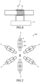
- FIGS. 7 and 8 illustrate the operation of each multipole element 260.
- the arrow on each first coil 8a represents the sense of a magnetic field produced by the first coil 8a.
- the arrow on each second coil 8b indicates the sense of a magnetic field produced by the second coil 8b.
- the multipole element 260 can have an inoperative mode in which the multipole element 260 produces no multipolar field as shown in FIG. 7 and an operative mode in which the multipole element 260 produces a multipolar field as shown in FIG. 8 .
- the magnetic field produced by the first coil 8a and the magnetic field produced by the second coil 8b are opposite in sense. Therefore, in the multipole element 260, the hexapolar field produced by energizing the first coil 8a and the hexapolar field produced by energizing the second coil 8b are opposite in sense.
- the magnetic fields produced respectively by the first coil 8a and the second coil 8b are identical in strength. Therefore, in the multipole element 260, the hexapolar fields produced respectively by energizing the first coil 8a and the second coil 8b cancel out each other. Consequently, the multipole element 260 gives rise to no hexapolar field.
- the hexapolar fields produced respectively by energizing the first coil 8a and the second coil 8b can be made equal in strength by making equal to each other the amounts of energization current respectively supplied to the first coil 8a and the second coil 8b.
- the first coil 8a and the second coil 8b may be different in the number of turns per unit length.
- the amount of energization current supplied to the first coil 8a and the amount of energization current supplied to the second coil 8b may be so adjusted that the hexapolar fields produced respectively by energizing the first coil 8a and the second coil 8b are equal in strength.
- the magnetic fields respectively produced by the first coil 8a and the second coil 8b are oriented in the same sense. Therefore, with the multipole element 260, the hexapolar fields produced respectively by energizing the first coil 8a and the second coil 8b are equal in sense. Thus, the hexapolar field generated by energizing the first coil 8a and the hexapolar field generated by energizing the second coil 8b combine additively. As a consequence, the multipole element 260 can produce a hexapolar field of greater strength.
- the multipole element 260 can be controllably switched between the inoperative mode and the operative mode by maintaining constant the sense of the magnetic field produced by the first coil 8a while varying the sense of the magnetic field produced by the second coil 8b.
- This switching in the multipole element 260 may also be controlled by varying the sense of the magnetic field produced by the first coil 8a while maintaining constant the sense of the magnetic field produced by the second coil 8b in a manner not illustrated.
- the sum of the electric power consumed by the first coil 8a and the electric power consumed by the second coil 8b in the inoperative mode of FIG. 7 is equal to the sum of the electric power consumed by the first coil 8a and the electric power consumed by the second coil 8b in the operative mode of FIG. 8 . Therefore, if the multipole element 260 is switched between the inoperative mode and the operative mode, the amount of heat of the multipole element 260 can be kept constant.
- P 1 be the electric power consumed by the first coil 8a and let I 1 be the energization current supplied to the first coil 8a which is assumed to have a resistance of R 1 .
- I 2 be the energization current supplied to the second coil 8b and let R 2 be the resistance of the second coil 8b.
- Switching between the inoperative mode and the operative mode of the multipole element 260 is carried out by switching the sense (polarity) of the energization current I 2 without varying either of the energization currents I 1 and I 2 .
- the sum of the electric powers P 1 and P 2 in the inoperative mode can be made equal to the sum of the electric powers P 1 and P 2 in the inoperative mode.
- the amount of heat of the multipole element 260 can be made uniform whether it is in the inoperative or operative mode. Hence, if the multipole element 260 is switched to its operative or inoperative mode, the amount of heat of the multipole element 260 can be maintained constant.
- FIGS. 9 and 10 show examples of the optical mode of the electron optical system 2.
- FIG. 9 illustrates a high-resolution STEM mode that is one example of the optical mode for correcting aberrations in the illumination optics 20 with the aberration corrector 26.
- the two stages of multipole elements 260 are each energized as shown in FIG. 8 , whereby the two stages of multipole elements 260 produce their respective hexapolar fields, thus correcting aberrations in the illumination optics 20.
- the electron beam can be greatly converged into an electron probe having a large convergence angle. Consequently, a high-intensity, very fine electron probe can be obtained, and high-resolution STEM images can be derived.
- the electron beam emitted from the electron source 10 is converged into an electron probe by the illumination optics 20.
- the electron probe is deflected in two dimensions by the illumination optics 20. Consequently, the sample S can be scanned with the electron probe.
- the electron probe transmitted through the sample S is passed to the STEM detector 50 by the imaging optics 40 and detected by the STEM detector 50.
- An STEM image can be obtained, for example, by detecting electrons transmitted through the sample S with the STEM detector 50 in synchronism with the scanning with the electron probe. Because aberrations in the illumination optics 20 can be corrected by the aberration corrector 26, a high-resolution STEM image can be obtained.
- FIG. 10 illustrates an STEM pencil beam mode that is one example of optical mode in which aberrations in the illumination optics 20 are not corrected with the aberration corrector 26.
- the aberration corrector 26 produces no multipolar field, and aberrations in the illumination optics 20 are not corrected.
- the two stages of multipole elements 260 are placed into the inoperative mode shown in FIG. 7 .
- each of the multipole elements 260 produces no hexapolar field.
- none of the four collector lenses 262, 264, 266, and 268 are energized.
- the STEM pencil beam mode small convergence angles on the order of mrad or less can be achieved. In this mode, no multipolar fields are generated; otherwise multipolar fields would induce large undesirable aberrations such as three-fold astigmatism, thus deteriorating the resolution.
- the STEM pencil beam mode is an optical mode suitable, for example, for the DPC (differential phase contrast) method.
- the DPC method enables acquisition of differential phase contrast (DPC) images.
- the convergence angle of the electron beam is reduced by the illumination optics 20 operating in the STEM pencil beam mode.
- the sample S is scanned with the electron beam having a small convergence angle.
- the amounts of deflection of the electron beam at multiple points caused by the electromagnetic field within the sample S are measured, and the electromagnetic field is visualized.
- the deflection of the electron beam caused by the electromagnetic field within the sample S can be detected using the segmented detector 52.
- the detector segments D1, D2, D3, and D4 produce the detection signals I 1 , I 2 , I 3 , and I 4 , respectively.
- the amount and direction of deflection of the electron beam caused by the electromagnetic field in the sample S can be found from the difference between the detection signals I 1 and I 3 , i.e., I 1 - I 3 , and from the difference between the detection signals I 2 and I 4 , i.e., I 2 - I 4 .
- a DPC image is an STEM image which is obtained by the DPC method and which provides visualization of the electromagnetic field within the sample. Note that the STEM pencil beam mode is also suitable for diffraction imaging and so on.
- FIG. 11 is a flowchart illustrating one example of processing sequence performed by the controller 60 to control the electron optical system 2.
- the electron optical system 2 has a first optical mode M1 in which aberrations are not corrected by the aberration corrector 26 as shown in FIG. 10 and a second optical mode M2 in which aberrations are corrected by the aberration corrector 26 as shown in FIG. 9 .
- the controller 60 accepts the selected optical mode for the electron optical system 2 (step S 100). More specifically, the controller 60 waits in a condition capable of accepting the selected optical mode for the electron optical system 2. For example, if the user selects either the first optical mode M1 or the second optical mode M2, the controller 60 accepts the selected optical mode. Such a selection of an optical mode is made by manipulation of an input device such as buttons, a mouse, or keys or by GUI (graphical user interface)-based manipulation.
- an input device such as buttons, a mouse, or keys or by GUI (graphical user interface)-based manipulation.
- the controller 60 causes the first coil 8a and the second coil 8b of the multipole element 260 to produce magnetic fields of opposite senses such that the multipole element 260 produces no multipolar field (step S 104). This can place the electron optical system 2 into the first optical mode M1.
- the controller 60 switches both of the two stages of multipole elements 260 from the operative mode to the inoperative mode. Consequently, in the aberration corrector 26, the two stages of multipole elements 260 produce no multipolar field and thus aberrations are not corrected.
- the controller 60 makes a switch from the operative to inoperative mode by reversing the polarity of the energization current supplied to the second coil 8b without varying either the amount of the energization current supplied to the first coil 8a or the amount of the energization current supplied to the second coil 8b.
- the controller 60 makes a switch from the operative to inoperative mode by reversing the polarity of the energization current supplied to the second coil 8b without varying either the amount of the energization current supplied to the first coil 8a or the amount of the energization current supplied to the second coil 8b.
- controller 60 energizes none of the four collector lenses 262, 264, 266, and 268. Consequently, the electron optical system 2 can be operated in the STEM pencil beam mode shown in FIG. 10 .
- the controller 60 After switching the optical mode of the electron optical system 2, the controller 60 makes a decision as to whether there is an instruction for ending the processing for controlling the electron optical system 2 (step S 106).
- the instruction for ending the processing is given by manipulation of an input device (such as buttons, a mouse, or a key) or by GUI-based manipulation.
- step S 106 If the controller 60 determines that there is no instruction for ending the processing (No at step S 106), control returns to step S 100, where the controller waits in a condition capable of accepting a selected optical mode of the electron optical system 2. If an optical mode is selected, the controller accepts the selected optical mode of the electron optical system 2 (step S 100).
- the controller 60 causes the first coil 8a and the second coil 8b of the multipole element 260 to produce magnetic fields of the same sense such that the multipole element 260 produces a multipolar field (step S 108). In consequence, the electron optical system 2 can be placed into the second optical mode M2.
- the controller 60 switches the two stages of multipole elements 260 from the inoperative to operative mode. Consequently, in the aberration corrector 26, the two stages of multipole elements 260 produce their respective multipolar fields, correcting aberrations.
- the controller 60 switches each multipole element 260 from the inoperative to operative mode by reversing the polarity of the energization current supplied to the second coil 8b without varying either of the amounts of the energization currents respectively supplied to the first coil 8a and the second coil 8b.
- the controller 60 switches each multipole element 260 from the inoperative to operative mode by reversing the polarity of the energization current supplied to the second coil 8b without varying either of the amounts of the energization currents respectively supplied to the first coil 8a and the second coil 8b.
- controller 60 operates all of the four collector lenses 262, 264, 266, and 268. Consequently, the electron optical system 2 can be operated in the high-resolution STEM mode illustrated in FIG. 9 .
- the controller 60 After switching the optical mode of the electron optical system 2, the controller 60 makes a decision as to whether there is an instruction for ending the processing for controlling the electron optical system 2 (step S 106). If the controller 60 determines that there is such an instruction (Yes at step S106), the controller ends the processing for controlling the electron optical system 2.
- the electron microscope 100 includes the electron optical system 2 which has the built-in aberration corrector 26 equipped with the multipole elements 260 each for producing a multipolar field.
- Each multipole element 260 has the plurality of magnetic polepieces 4.
- Each of the polepieces 4 includes the magnetic core 6, the first coil 8a wound around the core 6, and the second coil 8b wound around the core 6.
- the first coil 8a and the second coil 8b produce a first multipolar field and a second multipolar field, respectively, when energized.
- the first and second multipolar fields are identical in terms of symmetry.
- the first and second multipolar fields can be canceled out by causing these multipolar fields to have opposite senses.
- This makes it possible to control the activation and deactivation of the multipolar field from the multipole element 260 by varying the sense of the magnetic field produced by the second coil 8b. Consequently, the amount of heat of the multipole element 260 whose multipolar field is activated and the amount of heat of the multipole element 260 whose multipolar field is deactivated can be made equal to each other.
- FIG. 12 illustrates the operation of a conventional multipole element 260D having magnetic cores 6.
- a single coil 8 is wound around each one of the magnetic cores 6.
- Activation and deactivation of the multipolar field from the multipole element 260D are controlled by permitting or inhibiting the supply of an energization current to the coil 8. That is, when the multipolar field is deactivated, the energization current into the coil 8 is zero. Therefore, with the multipole element 260D, the amount of heat of the coil 8 varies greatly depending on whether the multipolar field is switched on or off. Accordingly, with the multipole element 260D, aberrations will vary from when the multipolar field is switched on or off until the temperature stabilizes. Especially, when the multipolar field is switched from off to on, the amount of heat of the coil 8 increases suddenly and aberrations will vary greatly.
- activation and deactivation of the multipolar field from the multipole element 260 can be controlled by the sense of the magnetic field produced by the second coil 8b. Therefore, the amount of heat produced by the coil while the multipolar field is activated can be made equal to the amount of heat produced by the coil while the multipolar field is deactivated. Consequently, variations in aberrations caused by switching of the multipolar field from deactivation to activation can be reduced.
- the electron microscope 100 includes the controller 60 for controlling the electron optical system 2.
- the controller 60 makes a switch between the inoperative mode in which each multipolar element 260 is inhibited from producing a multipolar field by causing the magnetic fields produced respectively by the first coil 8a and the second coil 8b to be oriented in opposite senses and the operative mode in which the multipolar element 260 is caused to produce a multipolar field by causing the magnetic fields produced respectively by the first coil 8a and the second coil 8b to be oriented in the same sense. Therefore, in the electron microscope 100, if the multipole element 260 is switched from the inoperative to the operative mode, the amount of heat of the multipole element 260 can be kept constant.
- the controller 60 controls the energization currents respectively supplied to the first coil 8a and the second coil 8b such that the sum of the electric powers respectively consumed by the first coil 8a and the second coil 8b in the inoperative mode is equal to the sum of the electric powers respectively consumed by the first coil 8a and the second coil 8b in the operative mode. Therefore, in the electron microscope 100, if the multipole element 260 is switched from the inoperative to operative mode, the amount of heat of the multipole element 260 can be kept constant.
- the controller 60 makes a switch between the first optical mode M1 in which aberrations are not corrected by the aberration corrector 26 and the second optical mode M2 in which aberrations are corrected by the aberration corrector 26.
- the controller 60 switches the multipole element 260 from its inoperative to operative mode. Therefore, in the electron microscope 100, variations of aberrations caused by the switching from the first optical mode M1 to the second optical mode M2 can be reduced.
- the electron optical system 2 includes the illumination optics 20 for irradiating the sample S with an electron beam.
- the aberration corrector 26 is incorporated in the illumination optics 20. Therefore, in the electron microscope 100, variations of aberrations caused by switching between the STEM pencil beam mode (first optical mode M1) and the high-resolution STEM mode (second optical mode M2) illustrated in FIG. 9 can be reduced.
- Each multipole element 260 includes the plurality of magnetic polepieces 4 for producing a multipolar field.
- Each of the polepieces 4 includes the magnetic core 6, the first coil 8a wound around the core 6, and the second coil 8b wound around the core 6.
- the first and second multipolar fields produced by energizing the first coil 8a and the second coil 8b, respectively, are identical in terms of symmetry.
- the first and second multipolar fields can be made to cancel out each other by orienting the first and second multipolar fields oppositely to each other. Accordingly, activation and deactivation of each multipolar field can be controlled by varying the sense of the magnetic field produced by the second coil 8b. Consequently, in the multipole element 260, the amount of heat generated by the multipole element 260 during deactivation of its magnetic field can be made equal to that generated by the multipole element 260 during activation of its magnetic field.
- the multipole element 260 can assume an inoperative mode and an operative mode. In the inoperative mode, no multipolar field is produced by causing magnetic fields produced respectively by the first coil 8a and the second coil 8b to be oriented in opposite senses. In the operative mode, a multipolar field is produced by causing the magnetic fields produced respectively by the first coil 8a and the second coil 8b to be oriented in the same sense. Therefore, the amount of heat from the multipole element 260 can be kept constant if it is switched either to the inoperative mode or to the operative mode.
- the control method according to the present invention is for use in the electron microscope 100 including the electron optical system 2 having the built-in aberration corrector 26 equipped with the multipole elements 260 each for producing a multipolar field.
- the control method involves the steps of: operating the electron optical system 2 in the first optical mode M1 in which aberrations are not corrected by the aberration corrector 26; and making a switch from the first optical mode M1 to the second optical mode M2 in which aberrations are corrected by the aberration corrector 26 and operating the electron optical system 2.
- the multipole elements 260 are switched from the inoperative to operative mode.
- the multipole elements 260 are switched from the inoperative mode, in which each multipole element 260 is inhibited from producing a multipolar field by causing the first coil 8a and the second coil 8b to produce magnetic fields of opposite senses to the operative mode, in which the first coil 8a and the second coil 8b are caused to produce magnetic fields of the same sense such that the multipole element 260 produces a multipolar field. Consequently, variations in aberrations caused by switching from the first optical mode M1 to the second optical mode M2 can be reduced.
- the STEM pencil beam mode of FIG. 10 is taken as one example of the first optical mode M1 in which aberrations are not corrected by the aberration corrector 26.
- the first optical mode M1 is not restricted to this.
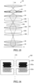
- FIG. 13 illustrates a further example of the optical mode of the electron optical system 2.
- An STEM pencil beam mode is shown in this figure as other example of the first optical mode M1 in which aberrations are not corrected by the illumination optics 20.
- the STEM pencil beam mode of FIG. 13 can achieve a convergence angle of less than 1 mrad which is smaller than achieved in the STEM pencil beam mode of FIG. 10 , by the use of the third collector lens 266.
- the controller 60 performs the above-described control operations of FIG. 11 even when a switch is made between the STEM pencil beam mode of FIG. 13 and the high-resolution STEM mode of FIG. 9 . Therefore, variations of aberrations caused by switching between these two modes can be reduced.
- the first optical mode M1 is a TEM mode in which an electron beam is directed parallel to the sample S.
- a further example is a low-magnification mode using a final magnification of less than 3,000X.
- the controller 60 performs the control operations of FIG. 11 . Therefore, when a switch is made between the TEM mode and the high-resolution STEM mode and when a switch is made between the low-magnification mode and the high-resolution STEM mode, variations of aberrations due to switching of the optical mode can be reduced.
- the multipolar field from each multipole element 260 is switched on or off while maintaining constant the amount of heat of the multipole element 260.
- the strength of the multipolar field produced by the multipole element 260 may be varied while maintaining constant the amount of heat of the multipole element 260.
- the controller 60 varies the strength of the multipolar field produced by each multipole element 260 by varying the ratio of the energization current supplied to the second coil 8b to the energization current supplied to the first coil 8a.
- the ratio of the energization current I 2 supplied to the second coil 8b to the energization current I 1 supplied to the first coil 8a i.e., I 2 /I 1
- the ratio of the strength of the second multipolar field produced by the second coil 8b to the strength of the first multipolar field produced by the first coil 8a varies, thus varying the strength of the mulipolar field generated by the multipole element 260.
- the first magnetic field and the second magnetic field produced respectively by the energization of the first coil 8a and the second coil 8b are oriented in opposite senses. Consequently, the first and second multipolar fields can be made to weaken each other. Furthermore, if the ratio I 2 /I 1 is varied, the sum of the electric power consumed by the first coil 8a and the electric power consumed by the second coil 8b is held constant. Consequently, the amount of heat of the multipole element 260 can be maintained constant if the multipolar field generated by the multipole element 260 is varied in strength.
- the controller 60 varies the strength of the multipolar field produced by the multipole element 260 from a first strength to a second strength different from the first strength by varying the ratio of the energization current I 2 supplied to the second coil 8b to the energization current I 1 supplied to the first coil 8a.
- the controller 60 controls the energization currents supplied respectively to the first coil 8a and the second coil 8b such that the sum of the electric power consumed by the first coil 8a and the electric power consumed by the second coil 8b when each multipole element 260 is made to produce a multipolar field of the first strength is equal to the sum of the electric power consumed by the first coil 8a and the electric power consumed by the second coil 8b when each multipole element 260 is made to produce a multipolar field of the second strength.
- the strength of the multipolar field produced by the multipole element 260 is varied from the first strength to the second strength, the amount of heat can be maintained constant.
- the foregoing embodiment is a scanning transmission electron microscope having the illumination optics 20 in which the aberration corrector 26 including the multipole elements 260 is incorporated.
- Another embodiment may be a transmission electron microscope (TEM) having the imaging optics 40 in which the aberration corrector 26 including the multipole elements 260 is incorporated. Incorporating the aberration corrector 26 into the imaging optics 40 permits correction of aberrations in the imaging optics 40.
- Two aberration correctors of the same design as the aberration corrector 26 may be prepared and incorporated respectively in the illumination optics 20 and the imaging optics 40.
- the electron microscope 100 may also be a scanning electron microscope (SEM) having an electron optical system equipped with the built-in aberration corrector 26.
- the multipolar field from each multipole element 260 is switched on and off while maintaining constant of the amount of heat of the multipole element 260.
- the magnetic field from each collector lens may be switched on and off while maintaining constant the amount of heat of the collector lens.
- FIG. 14 schematically illustrates the first collector lens 262.
- the first collector lens 262 includes a first coil 202a, a second coil 202b, and a yoke 204.
- the first coil 202a and the second coil 202b are covered with the yoke 204 that is made of a ferromagnetic material such as iron.
- the first coil 202a is wound about an optical axis OA.
- the second coil 202b is wound about the optical axis OA.
- the first coil 202a and the second coil 202b are wound in the same sense, for example.
- the first coil 202a and the second coil 202b produce a first magnetic field and a second magnetic field, respectively, on the optical axis OA.
- the first and second magnetic fields together form a lens magnetic field.
- the controller 60 switches off the lens magnetic field by orienting the first and second magnetic fields in opposite senses.
- the controller 60 switches on the lens magnetic field by orienting the first and second magnetic fields in the same sense.
- the controller 60 makes the sum of the electric powers consumed respectively by the first coil 202a and the second coil 202b when the lens magnetic field is deactivated equal to the sum of the electric powers consumed respectively by the first coil 202a and the second coil 202b when the lens magnetic field is activated. This makes it possible to maintain constant the amount of heat generated by the first collector lens 262 if the lens magnetic field is switched on or off.
- the other three collector lenses 264, 266, and 268 constituting the aberration corrector 26 are configured similarly. If the lens magnetic field is switched on or off, the amount of heat can be kept constant.
- the electron microscope 100 associated with the fourth modification if a switch is made from the first optical mode M1 in which aberrations are not corrected with the aberration corrector 26 as shown in FIG. 10 to the second optical mode M2 in which the aberrations are corrected with the aberration corrector 26 as shown in FIG. 9 , the amount of heat generated by the two stages of multipole elements 260 and the four collector lenses 262, 264, 266, 268 constituting the aberration corrector 26 can be maintained constant. Consequently, the aberration corrector 26 of high thermal stability can be accomplished.
- each multipole element 260 is so designed that the amount of heat of each element 260 is constant if the strength of the multipolar field is varied.
- each of the four collector lenses 262, 264, 266, and 268 constituting the aberration corrector 26 may be designed to produce a constant amount of heat if the lens magnetic field is varied, in the same manner as the multipole elements 260.
- the ratio of the energization current supplied to the second coil 202b to the energization current supplied to the first coil 202a is varied, the ratio of the strength of the magnetic field produced by the second coil 202b to the strength of the magnetic field produced by the first coil 202a changes, thus varying the strength of the lens magnetic field.
- the magnetic field produced by energization of the first coil 202a and the magnetic field produced by energization of the second coil 202b are made opposite in sense to each other so that these two magnetic fields weaken each other.
- the ratio of the energization current supplied to the second coil 202b to the energization current supplied to the first coil 202a is varied, the sum of the electric powers respectively consumed by the first coil 202a and the second coil 202b is kept constant. Consequently, if the strength of the lens magnetic field generated by the first collector lens 262 is varied, the amount of heat of this lens 262 can be maintained constant.
- the other three collector lenses 264, 266, and 268 making up the aberration corrector 26 are configured similarly. If the strength of the lens magnetic field is varied, the amount of heat can be retained constant.
- the amount of heat can be maintained constant if the multipolar field from the aberration corrector 26 is switched on or off, if the strength of the multipolar field is varied, or if the strength of the lens magnetic field is varied. Hence, a thermally stable aberration corrector can be accomplished.
- the multipole elements 260 are used in an aberration corrector.
- the multipole elements 260 may also be used in other apparatus.
- the multipole elements 260 may be used either in a monochromator for monochromating an electron beam or in an energy filter for selecting only electrons having energies in a certain range of energies from electrons emitted from a sample.
- an instrument such as a monochromator or an energy filter, a thermally stable instrument can be accomplished.
- the present invention is not restricted to the foregoing embodiments but rather can be implemented in various modified forms.
- the present invention embraces configurations (e.g., configurations identical in function or method) which are substantially identical to the configurations described in the above embodiments.
- the invention embraces configurations which are similar to the configurations described in the above embodiments except that their nonessential portions have been replaced.
- the invention embraces configurations which are similar to the configurations described in the above embodiments except that a well-known technique is added.
Landscapes
- Chemical & Material Sciences (AREA)
- Analytical Chemistry (AREA)
- Physics & Mathematics (AREA)
- Electromagnetism (AREA)
- Engineering & Computer Science (AREA)
- Power Engineering (AREA)
- Electron Sources, Ion Sources (AREA)
- Electron Tubes For Measurement (AREA)
Abstract
Description
- The present invention relates to an electron microscope and a control method therefor. The invention also relates to a multipole element used in such an electron microscope.
- In an electron microscope (such as a transmission electron microscope (TEM), a scanning transmission electron microscope (STEM), or a scanning electron microscope (SEM)), aberration correction is an important technique in acquiring high-resolution images.
- For example, patent document 1 discloses a two-stage hexapole field type spherical aberration corrector having two stages of hexapole elements each of which produces a hexapole field. In this spherical aberration corrector, positive spherical aberration in an objective lens is corrected by negative spherical aberrations produced respectively by the two stages of hexapole elements.
- A multipole element has a plurality of magnetic polepieces each of which includes a magnetic core and a coil wound around the core. The multipole element is made to produce a multipolar field by supplying an energization current to the coil.
- In a scanning transmission electron microscope, the electron optical system is operated in various modes according to purposes. For example, in a mode of operation for acquiring a high-resolution STEM image, aberrations in the illumination optics are corrected by an aberration corrector.
- In a differential phase contrast (DPC) method, the amount of deflection of an electron beam caused by the electromagnetic field within a sample is measured and the electromagnetic field is visualized. In a diffraction imaging method, a sample image is reconstructed from a diffraction pattern of the sample. When such a method is implemented, there is used an optical mode in which a small angle of convergence can be achieved. In this mode, aberrations are not corrected by the aberration corrector for the following reason. In an optical system where small angles of convergence occur, if a multipolar field is produced, large amounts of undesired aberrations arise, thus deteriorating the resolution.
- Patent document 1:
JP-A-2003-92078 - If a switch is made from an optical mode in which aberrations are not corrected by the aberration corrector to an optical mode in which the aberrations are corrected by the aberration corrector, each multipole element of the aberration corrector is switched from an inoperative mode in which no multipolar field is produced to an operative mode in which a multipolar field is produced. Consequently, energization currents flow through the coils, thus bringing about great variations in the temperatures of the multipole elements. This in turn varies aberrations arising from the aberration corrector. Hence, it has been impossible to perform an observation or analysis from when the optical mode is switched until fluctuations of aberrations settle down.
- One aspect of the electron microscope associated with the present invention comprises an electron optical system having a built-in aberration corrector equipped with multipole elements each for producing a multipolar field. Each of the multipole elements includes a plurality of magnetic polepieces. Each of the magnetic polepieces includes a magnetic core, a first coil wound around the core, and a second coil wound around the core. The first and second coils produce a first multipolar field and a second multipolar field, respectively, when energized. The first and second multipolar fields are identical in terms of symmetry.
- In this electron microscope, the first and second multipolar fields can be made to cancel out each other by orienting the first and second multipolar fields in opposite senses. Therefore, activation and deactivation of the multipolar field from each multipole element can be controlled by varying the sense of the magnetic field produced by the second or first coil. Consequently, the amount of heat of the multipole element in the presence of the multipolar field can be made equal to the amount of heat of the multipole element in the absence of the multipolar field. Thus, when a switch is made in this electron microscope between the non-correcting optical mode in which aberrations are not corrected by the aberration corrector and the aberration correcting optical mode in which aberrations are corrected by the aberration corrector, there occur less aberration variations.
- One aspect of the multipole element associated with the present invention comprises a plurality of magnetic polepieces for producing a multipolar field. Each of the magnetic polepieces includes a magnetic core, a first coil wound around the core, and a second coil wound around the core. The first and second coils produce a first multipolar field and a second multipolar field, respectively, when energized. The first and second multipolar fields are identical in terms of symmetry.
- With this multipole element, the first and second multipolar fields can be made to cancel out each other by orienting the first and second multipolar fields in opposite senses. Therefore, activation and deactivation of the multipolar field from each multipole element can be controlled by varying the sense of the magnetic field produced by the second or first coil. Consequently, with this multipole element, the amount of heat generated when the multipolar field is activated can be made equal to the amount of heat generated when the multipolar field is deactivated.
- One aspect of the control method associated with the present invention is for use in controlling an electron microscope comprising an electron optical system having a built-in aberration corrector equipped with multipole elements each for producing a multipolar field. The control method comprises the steps of: operating the electron optical system in a first optical mode in which aberrations are not corrected by the aberration corrector; and making a switch from the first optical mode to a second optical mode in which aberrations are corrected by the aberration corrector and operating the electron optical system. Each of the multipole elements includes a plurality of magnetic polepieces. Each of the magnetic polepieces includes a magnetic core, a first coil wound around the core, and a second coil wound around the core. The first and second coils produce a first multipolar field and a second multipolar field, respectively, when energized. The first and second multipolar fields are identical in terms of symmetry. Each of the multipole elements has an inoperative mode and an operative mode. In the inoperative mode, no multipolar field is produced by causing the magnetic fields generated by the first and second coils, respectively, to be oriented in opposite senses. In the operative mode, a multipolar field is produced by causing the magnetic fields respectively produced by the first and second coils to be oriented in the same sense. In the step of making a switch from the first optical mode to the second optical mode, the multipole element is switched from the inoperative mode to the operative mode.
- This control method for the electron microscope involves the step of making a switch from the first optical mode to the second optical mode. In this step, the multipole element is switched from the inoperative mode, in which no multipolar field is produced from the multipole element by causing the magnetic fields respectively generated by the first and second coils to be oriented in opposite senses, to the operative mode, in which the magnetic fields respectively generated by the first and second coils are oriented in the same sense such that a multipolar field is produced from the multipole element. Consequently, there occur less aberration variations when a switch is made from the first to the second optical mode.
-
-
FIG. 1 is a diagram showing the configuration of an electron microscope associated with one embodiment of the present invention. -
FIG. 2 is a schematic diagram of the sensitive surface of a segmented detector. -
FIG. 3 is a diagram illustrating the configuration of illumination optics. -
FIG. 4 is a schematic diagram of one multipole element. -
FIG. 5 is a schematic diagram of one magnetic polepiece. -
FIG. 6 is a schematic diagram of a modification of the magnetic polepiece ofFIG. 5 . -
FIG. 7 is a diagram similar toFIG. 4 , but illustrating one operative mode of the multipole element. -
FIG. 8 is a diagram similar toFIG. 7 , but illustrating the other operative mode of the multipole element. -
FIG. 9 is an electron ray diagram illustrating one example of the optical mode of an electron optical system. -
FIG. 10 is an electron ray diagram illustrating another example of the optical mode of the electron optical system. -
FIG. 11 is a flowchart illustrating one example of processing sequence performed by a controller to control the electron optical system. -
FIG. 12 is a diagram illustrating the operative modes of a conventional multipole element. -
FIG. 13 is an electron ray diagram illustrating a further example of the optical mode of the electron optical system. -
FIG. 14 is a schematic cross-sectional view of one collector lens. - The preferred embodiments of the present invention are hereinafter described in detail with reference to the drawings. It is to be understood that the embodiments set forth below are not intended to unduly restrict the content of the present invention delineated by the claims and that not all the configurations set forth hereinafter are essential constituent components of the present invention.
- First, an electron microscope associated with one embodiment of the present invention is described by referring to
FIG. 1 , which shows the configuration of the electron microscope, 100. - As shown, the
electron microscope 100 includes anelectron source 10, an electronoptical system 2, asample stage 30, anSTEM detector 50, asegmented detector 52, and acontroller 60. The electronoptical system 2 includesillumination optics 20 andimaging optics 40. Theelectron microscope 100 is a scanning transmission electron microscope (STEM) having anaberration corrector 26 incorporated in theillumination optics 20. - The
electron source 10 which emits an electron beam is an electron gun, for example, that emits the electron beam by accelerating electrons with an anode after the electrons are released from a cathode. The electronoptical system 2 includes theillumination optics 20 and theimaging optics 40 as mentioned above. The electron beam emitted from theelectron source 10 is directed at a sample S through theillumination optics 20 which, for example, focuses the electron beam from theelectron source 10 into an electron probe that scans the sample S. Theimaging optics 40 images the electrons transmitted through the sample S. The electron beam transmitted through the sample S is passed onto theSTEM detector 50 and onto thesegmented detector 52 via theimaging optics 40. - The
STEM detector 50 detects electrons transmitted through the sample S. For example, theSTEM detector 50 is a dark-field STEM detector using an annular detector for detecting electrons inelastically scattered through high angles from the sample S. - The
segmented detector 52 has an electronsensitive surface 53 for detecting the electrons transmitted through the sample S, thesensitive surface 53 being split into a plurality of detector segments. -
FIG. 2 schematically shows thesensitive surface 53 of the segmenteddetector 52. As shown, thesensitive surface 53 is divided into detector segments D1, D2, D3, and D4 which are formed by angularly (circumferentially) quartering the annularsensitive surface 53 of the segmenteddetector 52. Each of the four detector segments D1-D4 can independently detect electrons. - Note that there is no restriction on the number of the detector segments of the
sensitive surface 53. That is, thesegmented detector 52 may have a plurality of detector segments which are separated from each other radially and circumferentially in a manner not illustrated. For example, thesensitive surface 53 of the segmenteddetector 52 may have 16 detector segments by being radially divided by 4 and circumferentially divided by 4. - The
segmented detector 52 includes, for example, an electron-to-light converter (scintillator) for converting electrons into light, light transmission paths (consisting of a bundle of optical fibers) for separating the electron-to-light converter into the detector segments D1, D2, D3, and D4 and transmitting light signals from the detector segments D1-D4, and a plurality of optical detectors (photoelectron multipliers) for producing detection signals responsive to the electron intensities respectively detected by the detector segments D1-D4. Thesegmented detector 52 may be a semiconductor detector having a plurality of detector segments. Thesample stage 30 mechanically supports the sample S held to asample holder 32 and permits the sample S to be placed in position. - The
controller 60 includes a processor (such as a CPU (central processing unit)) and storage devices (such as a RAM (random access memory) and a ROM (read-only memory)). Programs and data for carrying out various control operations are stored in the storage devices. The functions of thecontroller 60 can be implemented by executing programs by means of the processor. Thecontroller 60 controls various parts of theelectron microscope 100 via driver circuitry (not shown). -
FIG. 3 illustrates the configuration of theillumination optics 20. As shown, theillumination optics 20 includes afirst condenser lens 21, asecond condenser lens 22, acondenser aperture 23, athird condenser lens 24, the above-describedaberration corrector 26, and acondenser minilens 28. Theillumination optics 20 further includes a frontmagnetic field 29 produced in front of the sample S by the objective lens. - The
first condenser lens 21,second condenser lens 22, andthird condenser lens 24 are arranged in this order from a side of theelectron source 10. These threecondenser lenses condenser aperture 23 is placed within thesecond condenser lens 22. - The
aberration corrector 26 is disposed between thethird condenser lens 24 and thecondenser minilens 28. Theaberration corrector 26 is incorporated in theillumination optics 20, and is a spherical aberration corrector for correcting spherical aberration in theillumination optics 20. Theaberration corrector 26 includes two stages ofmultipole elements 260, afirst collector lens 262, asecond collector lens 264, athird collector lens 266, and afourth collector lens 268. Theaberration corrector 26 is a two-stage hexapole spherical aberration corrector having the two stages ofmultipole elements 260. - Each
multipole element 260 produces a hexapolar magnetic field of three-fold symmetry. For example, eachmultipole element 260 is a hexapole element, a dodecapole element, or any other multipole element capable of generating a hexapolar magnetic field. - The
first collector lens 262,second collector lens 264, andthird collector lens 266 are placed between the first stage ofmultipole element 260 and the second stage ofmultipole element 260. These threecollector lenses multipole element 260 to the principal optical plane of the second stage ofmultipole element 260. This transfer optics transfers an image equivalent to the output image of the first stage ofmultipole element 260 to the second stage ofmultipole element 260. Thesecond collector lens 264 is positioned between thefirst collector lens 262 and thethird collector lens 266. Thesecond collector lens 264 imparts a rotary action to the electron beam without applying a light focusing action to the beam. Consequently, the rotation occurring between the first stage ofmultipole element 260 and the second stage ofmultipole element 260 relative to the electron orbit can be corrected. Thefourth collector lens 268 is disposed between the second stage ofmultipole element 260 and the condenser minilens 28 and serves as a transfer lens. - Each
multipole element 260 has a thickness in the direction of travel of the electron beam, i.e., along the optical axis OA. That is, themultipole element 260 produces a negative spherical aberration as a combination aberration of three-fold astigmatisms in a hexapolar field having a thickness. The combination aberration referred to herein is a combination ofaberrations 1 and 2 when the aberration 1 occurs at some location, propagates a distance, thereby varies the point of incidence, and is affected by theother aberration 2. - Positive spherical aberration in the
illumination optics 20 can be corrected by negative spherical aberrations respectively produced by the first stage ofmultipole element 260 and the second stage ofmultipole element 260. - The three-fold astigmatism produced by the second stage of
multipole element 260 is opposite in sense to the three-fold astigmatism produced by the first stage ofmultipole element 260. Therefore, the three-fold astigmatism produced by the first stage ofmultipole element 260 can be canceled out by the three-fold astigmatism produced by the second stage ofmultipole element 260. - There are no restrictions on the
aberration corrector 26 as long as it can correct aberrations using themultipole elements 260. Theaberration corrector 26 may also be of the three-stage, hexapolar field type. - The condenser minilens 28 is located between the
aberration corrector 26 and themagnetic field 29 produced forwardly of the objective lens, and is operative to create an electron beam having a convergence angle adapted for the optical mode. The convergence angle can be varied by varying the excitation of thecondenser minilens 28. Themagnetic field 29 produced forwardly of the objective lens functions as a condenser lens for converging an electron beam. - The
illumination optics 20 includes a scan deflector (not shown) for deflecting the electron beam in two dimensions. The scan deflector permits the sample S to be scanned with the electron beam. - The
multipole elements 260 are next described.FIG. 4 schematically shows the configuration of eachmultipole element 260. It is herein assumed that themultipole element 260 has six magnetic polepieces. The number of the magnetic polepieces of themultipole element 260 can be appropriately varied according to the symmetry of the generated magnetic fields. - As shown in
FIG. 4 , themultipole element 260 has the sixmagnetic polepieces 4 which are disposed radially with respect to an optical axis OA. In themultipole element 260, a hexapolar field of three-fold symmetry is produced by imparting alternately opposite polarities to themagnetic polepieces 4. - Each
magnetic polepiece 4 includes amagnetic core 6, afirst coil 8a, and asecond coil 8b. Themagnetic core 6 is a metallic rodlike member as made of a soft magnetic material. Each of the sixmagnetic cores 6 making up themultipole element 260 is wrapped with thefirst coil 8a and thesecond coil 8b. Therefore, the multipolar field created by themultipole element 260 by energization of thefirst coil 8a and the multipolar field created by themultipole element 260 by energization of thesecond coil 8b have the same symmetry. In the illustrated example, the multipolar field created by themultipole element 260 by energization of thefirst coil 8a is a hexapolar field of three-fold symmetry. Similarly, the multipolar field created by themultipole element 260 by energization of thesecond coil 8b is a hexapolar field of three-fold symmetry. -
FIG. 5 schematically illustrates onemagnetic polepiece 4. Thefirst coil 8a is wound on themagnetic core 6. Thesecond coil 8b is also wound on themagnetic core 6. In the example ofFIGS. 4 and 5 , thefirst coil 8a is disposed near the rear end of themagnetic polepiece 4, while thesecond coil 8b is disposed near the front end of thepolepiece 4. Alternatively, thefirst coil 8a and thesecond coil 8b may be located near the front end and the rear end, respectively, of themagnetic polepiece 4 in a manner not illustrated. Thefirst coil 8a and thesecond coil 8b are supplied with energization currents from apower supply 9. - The
power supply 9 supplies the energization currents, which can be different in polarity or sense, for example, to thefirst coil 8a and thesecond coil 8b. Furthermore, thepower supply 9 can supply different amounts of energization current to thefirst coil 8a and thesecond coil 8b. Thepower supply 9 is under control of thecontroller 60. - The
first coil 8a and thesecond coil 8b are wound in the same sense. Therefore, by energizing thefirst coil 8a and thesecond coil 8b with energization currents of the same polarity, thefirst coil 8a and thesecond coil 8b produce magnetic fields of the same sense. Furthermore, by energizing thefirst coil 8a and thesecond coil 8b with energization currents of different polarities, thefirst coil 8a and thesecond coil 8b generate magnetic fields of opposite senses. - The
first coil 8a and thesecond coil 8b may be wound in opposite senses in a manner not illustrated. In this case, by energizing thefirst coil 8a and thesecond coil 8b with energization currents of the same polarity, thefirst coil 8a and thesecond coil 8b develop magnetic fields having opposite senses. Furthermore, by energizing thefirst coil 8a and thesecond coil 8b with energization currents of different polarities, thefirst coil 8a and thesecond coil 8b generate magnetic fields having the same sense. -
FIG. 6 shows a modification of themagnetic polepiece 4 ofFIG. 5 . As shown, thefirst coil 8a and thesecond coil 8b may be arranged to overlap each other. In this case, nonuniformities in the amount of heat among the coil positions can be reduced. -
FIGS. 7 and8 illustrate the operation of eachmultipole element 260. In these two figures, the arrow on eachfirst coil 8a represents the sense of a magnetic field produced by thefirst coil 8a. The arrow on eachsecond coil 8b indicates the sense of a magnetic field produced by thesecond coil 8b. - The
multipole element 260 can have an inoperative mode in which themultipole element 260 produces no multipolar field as shown inFIG. 7 and an operative mode in which themultipole element 260 produces a multipolar field as shown inFIG. 8 . - In the inoperative mode shown in
FIG. 7 , for each of the sixmagnetic polepieces 4, the magnetic field produced by thefirst coil 8a and the magnetic field produced by thesecond coil 8b are opposite in sense. Therefore, in themultipole element 260, the hexapolar field produced by energizing thefirst coil 8a and the hexapolar field produced by energizing thesecond coil 8b are opposite in sense. - For each of the six
magnetic polepieces 4, the magnetic fields produced respectively by thefirst coil 8a and thesecond coil 8b are identical in strength. Therefore, in themultipole element 260, the hexapolar fields produced respectively by energizing thefirst coil 8a and thesecond coil 8b cancel out each other. Consequently, themultipole element 260 gives rise to no hexapolar field. - If the
first coil 8a and thesecond coil 8b are equal in number of turns per unit length, the hexapolar fields produced respectively by energizing thefirst coil 8a and thesecond coil 8b can be made equal in strength by making equal to each other the amounts of energization current respectively supplied to thefirst coil 8a and thesecond coil 8b. - The
first coil 8a and thesecond coil 8b may be different in the number of turns per unit length. In this case, the amount of energization current supplied to thefirst coil 8a and the amount of energization current supplied to thesecond coil 8b may be so adjusted that the hexapolar fields produced respectively by energizing thefirst coil 8a and thesecond coil 8b are equal in strength. - In the operative mode shown in
FIG. 8 , for each of the sixmagnetic polepieces 4, the magnetic fields respectively produced by thefirst coil 8a and thesecond coil 8b are oriented in the same sense. Therefore, with themultipole element 260, the hexapolar fields produced respectively by energizing thefirst coil 8a and thesecond coil 8b are equal in sense. Thus, the hexapolar field generated by energizing thefirst coil 8a and the hexapolar field generated by energizing thesecond coil 8b combine additively. As a consequence, themultipole element 260 can produce a hexapolar field of greater strength. - In this way, the
multipole element 260 can be controllably switched between the inoperative mode and the operative mode by maintaining constant the sense of the magnetic field produced by thefirst coil 8a while varying the sense of the magnetic field produced by thesecond coil 8b. This switching in themultipole element 260 may also be controlled by varying the sense of the magnetic field produced by thefirst coil 8a while maintaining constant the sense of the magnetic field produced by thesecond coil 8b in a manner not illustrated. - The sum of the electric power consumed by the
first coil 8a and the electric power consumed by thesecond coil 8b in the inoperative mode ofFIG. 7 is equal to the sum of the electric power consumed by thefirst coil 8a and the electric power consumed by thesecond coil 8b in the operative mode ofFIG. 8 . Therefore, if themultipole element 260 is switched between the inoperative mode and the operative mode, the amount of heat of themultipole element 260 can be kept constant. - Let P1 be the electric power consumed by the
first coil 8a and let I1 be the energization current supplied to thefirst coil 8a which is assumed to have a resistance of R1. The electric power P1 is given by P1 = I1 2R1. Similarly, let I2 be the energization current supplied to thesecond coil 8b and let R2 be the resistance of thesecond coil 8b. The electric power P2 consumed by thesecond coil 8b is given by P2 = I2 2R2. Switching between the inoperative mode and the operative mode of themultipole element 260 is carried out by switching the sense (polarity) of the energization current I2 without varying either of the energization currents I1 and I2. Therefore, the sum of the electric powers P1 and P2 in the inoperative mode can be made equal to the sum of the electric powers P1 and P2 in the inoperative mode. In consequence, the amount of heat of themultipole element 260 can be made uniform whether it is in the inoperative or operative mode. Hence, if themultipole element 260 is switched to its operative or inoperative mode, the amount of heat of themultipole element 260 can be maintained constant. - The operation of the
electron microscope 100 is next described.FIGS. 9 and10 show examples of the optical mode of the electronoptical system 2.FIG. 9 illustrates a high-resolution STEM mode that is one example of the optical mode for correcting aberrations in theillumination optics 20 with theaberration corrector 26. In particular, the two stages ofmultipole elements 260 are each energized as shown inFIG. 8 , whereby the two stages ofmultipole elements 260 produce their respective hexapolar fields, thus correcting aberrations in theillumination optics 20. - In the high-resolution STEM mode, the electron beam can be greatly converged into an electron probe having a large convergence angle. Consequently, a high-intensity, very fine electron probe can be obtained, and high-resolution STEM images can be derived.
- In the high-resolution STEM mode, the electron beam emitted from the
electron source 10 is converged into an electron probe by theillumination optics 20. The electron probe is deflected in two dimensions by theillumination optics 20. Consequently, the sample S can be scanned with the electron probe. The electron probe transmitted through the sample S is passed to theSTEM detector 50 by theimaging optics 40 and detected by theSTEM detector 50. An STEM image can be obtained, for example, by detecting electrons transmitted through the sample S with theSTEM detector 50 in synchronism with the scanning with the electron probe. Because aberrations in theillumination optics 20 can be corrected by theaberration corrector 26, a high-resolution STEM image can be obtained. -
FIG. 10 illustrates an STEM pencil beam mode that is one example of optical mode in which aberrations in theillumination optics 20 are not corrected with theaberration corrector 26. In this STEM pencil beam mode ofFIG. 10 , theaberration corrector 26 produces no multipolar field, and aberrations in theillumination optics 20 are not corrected. More specifically, the two stages ofmultipole elements 260 are placed into the inoperative mode shown inFIG. 7 . As a result, each of themultipole elements 260 produces no hexapolar field. Also, none of the fourcollector lenses - In the STEM pencil beam mode, small convergence angles on the order of mrad or less can be achieved. In this mode, no multipolar fields are generated; otherwise multipolar fields would induce large undesirable aberrations such as three-fold astigmatism, thus deteriorating the resolution. The STEM pencil beam mode is an optical mode suitable, for example, for the DPC (differential phase contrast) method.
- In the STEM pencil beam mode, the DPC method enables acquisition of differential phase contrast (DPC) images. For example, the convergence angle of the electron beam is reduced by the
illumination optics 20 operating in the STEM pencil beam mode. The sample S is scanned with the electron beam having a small convergence angle. The amounts of deflection of the electron beam at multiple points caused by the electromagnetic field within the sample S are measured, and the electromagnetic field is visualized. The deflection of the electron beam caused by the electromagnetic field within the sample S can be detected using the segmenteddetector 52. The detector segments D1, D2, D3, and D4 produce the detection signals I1, I2, I3, and I4, respectively. For example, the amount and direction of deflection of the electron beam caused by the electromagnetic field in the sample S can be found from the difference between the detection signals I1 and I3, i.e., I1 - I3, and from the difference between the detection signals I2 and I4, i.e., I2 - I4. A DPC image is an STEM image which is obtained by the DPC method and which provides visualization of the electromagnetic field within the sample. Note that the STEM pencil beam mode is also suitable for diffraction imaging and so on. -
FIG. 11 is a flowchart illustrating one example of processing sequence performed by thecontroller 60 to control the electronoptical system 2. In the following description, it is assumed that the electronoptical system 2 has a first optical mode M1 in which aberrations are not corrected by theaberration corrector 26 as shown inFIG. 10 and a second optical mode M2 in which aberrations are corrected by theaberration corrector 26 as shown inFIG. 9 . - The
controller 60 accepts the selected optical mode for the electron optical system 2 (step S 100). More specifically, thecontroller 60 waits in a condition capable of accepting the selected optical mode for the electronoptical system 2. For example, if the user selects either the first optical mode M1 or the second optical mode M2, thecontroller 60 accepts the selected optical mode. Such a selection of an optical mode is made by manipulation of an input device such as buttons, a mouse, or keys or by GUI (graphical user interface)-based manipulation. - If the first optical mode M1 is selected (M1 at step S102), the
controller 60 causes thefirst coil 8a and thesecond coil 8b of themultipole element 260 to produce magnetic fields of opposite senses such that themultipole element 260 produces no multipolar field (step S 104). This can place the electronoptical system 2 into the first optical mode M1. - When a switch is made from the second optical mode M2 to the first optical mode M1, the
controller 60 switches both of the two stages ofmultipole elements 260 from the operative mode to the inoperative mode. Consequently, in theaberration corrector 26, the two stages ofmultipole elements 260 produce no multipolar field and thus aberrations are not corrected. - At this time, the
controller 60 makes a switch from the operative to inoperative mode by reversing the polarity of the energization current supplied to thesecond coil 8b without varying either the amount of the energization current supplied to thefirst coil 8a or the amount of the energization current supplied to thesecond coil 8b. As a result, if themultipole element 260 is switched from the operative to inoperative mode, the amount of heat of themultipole element 260 can be kept constant. - Furthermore, the
controller 60 energizes none of the fourcollector lenses optical system 2 can be operated in the STEM pencil beam mode shown inFIG. 10 . - After switching the optical mode of the electron
optical system 2, thecontroller 60 makes a decision as to whether there is an instruction for ending the processing for controlling the electron optical system 2 (step S 106). The instruction for ending the processing is given by manipulation of an input device (such as buttons, a mouse, or a key) or by GUI-based manipulation. - If the
controller 60 determines that there is no instruction for ending the processing (No at step S 106), control returns to stepS 100, where the controller waits in a condition capable of accepting a selected optical mode of the electronoptical system 2. If an optical mode is selected, the controller accepts the selected optical mode of the electron optical system 2 (step S 100). - If the second optical mode M2 is selected (M2 at step S 102), the
controller 60 causes thefirst coil 8a and thesecond coil 8b of themultipole element 260 to produce magnetic fields of the same sense such that themultipole element 260 produces a multipolar field (step S 108). In consequence, the electronoptical system 2 can be placed into the second optical mode M2. - When a switch is made from the first optical mode M1 to the second optical mode M2, the
controller 60 switches the two stages ofmultipole elements 260 from the inoperative to operative mode. Consequently, in theaberration corrector 26, the two stages ofmultipole elements 260 produce their respective multipolar fields, correcting aberrations. - At this time, the
controller 60 switches eachmultipole element 260 from the inoperative to operative mode by reversing the polarity of the energization current supplied to thesecond coil 8b without varying either of the amounts of the energization currents respectively supplied to thefirst coil 8a and thesecond coil 8b. As a result, if themultipole element 260 is switched from the inoperative to operative mode, the amount of heat of themultipole element 260 can be kept constant. - In addition, the
controller 60 operates all of the fourcollector lenses optical system 2 can be operated in the high-resolution STEM mode illustrated inFIG. 9 . - After switching the optical mode of the electron
optical system 2, thecontroller 60 makes a decision as to whether there is an instruction for ending the processing for controlling the electron optical system 2 (step S 106). If thecontroller 60 determines that there is such an instruction (Yes at step S106), the controller ends the processing for controlling the electronoptical system 2. - The
electron microscope 100 includes the electronoptical system 2 which has the built-inaberration corrector 26 equipped with themultipole elements 260 each for producing a multipolar field. Eachmultipole element 260 has the plurality ofmagnetic polepieces 4. Each of thepolepieces 4 includes themagnetic core 6, thefirst coil 8a wound around thecore 6, and thesecond coil 8b wound around thecore 6. Thefirst coil 8a and thesecond coil 8b produce a first multipolar field and a second multipolar field, respectively, when energized. The first and second multipolar fields are identical in terms of symmetry. - Therefore, in the
electron microscope 100, the first and second multipolar fields can be canceled out by causing these multipolar fields to have opposite senses. This makes it possible to control the activation and deactivation of the multipolar field from themultipole element 260 by varying the sense of the magnetic field produced by thesecond coil 8b. Consequently, the amount of heat of themultipole element 260 whose multipolar field is activated and the amount of heat of themultipole element 260 whose multipolar field is deactivated can be made equal to each other. -
FIG. 12 illustrates the operation of aconventional multipole element 260D havingmagnetic cores 6. Asingle coil 8 is wound around each one of themagnetic cores 6. Activation and deactivation of the multipolar field from themultipole element 260D are controlled by permitting or inhibiting the supply of an energization current to thecoil 8. That is, when the multipolar field is deactivated, the energization current into thecoil 8 is zero. Therefore, with themultipole element 260D, the amount of heat of thecoil 8 varies greatly depending on whether the multipolar field is switched on or off. Accordingly, with themultipole element 260D, aberrations will vary from when the multipolar field is switched on or off until the temperature stabilizes. Especially, when the multipolar field is switched from off to on, the amount of heat of thecoil 8 increases suddenly and aberrations will vary greatly. - In contrast, in the
inventive electron microscope 100, activation and deactivation of the multipolar field from themultipole element 260 can be controlled by the sense of the magnetic field produced by thesecond coil 8b. Therefore, the amount of heat produced by the coil while the multipolar field is activated can be made equal to the amount of heat produced by the coil while the multipolar field is deactivated. Consequently, variations in aberrations caused by switching of the multipolar field from deactivation to activation can be reduced. - Accordingly, with the
electron microscope 100, even immediately after switching, for example, from the STEM pencil beam mode in which aberrations are not corrected by theaberration corrector 26 to the high-resolution STEM mode in which aberrations are corrected by theaberration corrector 26, high-resolution STEM observations are possible. - The
electron microscope 100 includes thecontroller 60 for controlling the electronoptical system 2. Thecontroller 60 makes a switch between the inoperative mode in which eachmultipolar element 260 is inhibited from producing a multipolar field by causing the magnetic fields produced respectively by thefirst coil 8a and thesecond coil 8b to be oriented in opposite senses and the operative mode in which themultipolar element 260 is caused to produce a multipolar field by causing the magnetic fields produced respectively by thefirst coil 8a and thesecond coil 8b to be oriented in the same sense. Therefore, in theelectron microscope 100, if themultipole element 260 is switched from the inoperative to the operative mode, the amount of heat of themultipole element 260 can be kept constant. - Furthermore, in the
electron microscope 100, thecontroller 60 controls the energization currents respectively supplied to thefirst coil 8a and thesecond coil 8b such that the sum of the electric powers respectively consumed by thefirst coil 8a and thesecond coil 8b in the inoperative mode is equal to the sum of the electric powers respectively consumed by thefirst coil 8a and thesecond coil 8b in the operative mode. Therefore, in theelectron microscope 100, if themultipole element 260 is switched from the inoperative to operative mode, the amount of heat of themultipole element 260 can be kept constant. - Further, in the
electron microscope 100, thecontroller 60 makes a switch between the first optical mode M1 in which aberrations are not corrected by theaberration corrector 26 and the second optical mode M2 in which aberrations are corrected by theaberration corrector 26. When the electronoptical system 2 is switched from the first optical mode M1 to the second optical mode M2, thecontroller 60 switches themultipole element 260 from its inoperative to operative mode. Therefore, in theelectron microscope 100, variations of aberrations caused by the switching from the first optical mode M1 to the second optical mode M2 can be reduced. - In the
electron microscope 100, the electronoptical system 2 includes theillumination optics 20 for irradiating the sample S with an electron beam. Theaberration corrector 26 is incorporated in theillumination optics 20. Therefore, in theelectron microscope 100, variations of aberrations caused by switching between the STEM pencil beam mode (first optical mode M1) and the high-resolution STEM mode (second optical mode M2) illustrated inFIG. 9 can be reduced. - Each
multipole element 260 includes the plurality ofmagnetic polepieces 4 for producing a multipolar field. Each of thepolepieces 4 includes themagnetic core 6, thefirst coil 8a wound around thecore 6, and thesecond coil 8b wound around thecore 6. The first and second multipolar fields produced by energizing thefirst coil 8a and thesecond coil 8b, respectively, are identical in terms of symmetry. - Therefore, in the
multipole element 260, the first and second multipolar fields can be made to cancel out each other by orienting the first and second multipolar fields oppositely to each other. Accordingly, activation and deactivation of each multipolar field can be controlled by varying the sense of the magnetic field produced by thesecond coil 8b. Consequently, in themultipole element 260, the amount of heat generated by themultipole element 260 during deactivation of its magnetic field can be made equal to that generated by themultipole element 260 during activation of its magnetic field. - The
multipole element 260 can assume an inoperative mode and an operative mode. In the inoperative mode, no multipolar field is produced by causing magnetic fields produced respectively by thefirst coil 8a and thesecond coil 8b to be oriented in opposite senses. In the operative mode, a multipolar field is produced by causing the magnetic fields produced respectively by thefirst coil 8a and thesecond coil 8b to be oriented in the same sense. Therefore, the amount of heat from themultipole element 260 can be kept constant if it is switched either to the inoperative mode or to the operative mode. - The control method according to the present invention is for use in the
electron microscope 100 including the electronoptical system 2 having the built-inaberration corrector 26 equipped with themultipole elements 260 each for producing a multipolar field. The control method involves the steps of: operating the electronoptical system 2 in the first optical mode M1 in which aberrations are not corrected by theaberration corrector 26; and making a switch from the first optical mode M1 to the second optical mode M2 in which aberrations are corrected by theaberration corrector 26 and operating the electronoptical system 2. During the step of making a switch from the first optical mode M1 to the second optical mode M2, themultipole elements 260 are switched from the inoperative to operative mode. - Therefore, in the control method for the
electron microscope 100, during the step of making a switch from the first optical mode M1 to the second optical mode M2, themultipole elements 260 are switched from the inoperative mode, in which eachmultipole element 260 is inhibited from producing a multipolar field by causing thefirst coil 8a and thesecond coil 8b to produce magnetic fields of opposite senses to the operative mode, in which thefirst coil 8a and thesecond coil 8b are caused to produce magnetic fields of the same sense such that themultipole element 260 produces a multipolar field. Consequently, variations in aberrations caused by switching from the first optical mode M1 to the second optical mode M2 can be reduced. - In the above embodiment, the STEM pencil beam mode of
FIG. 10 is taken as one example of the first optical mode M1 in which aberrations are not corrected by theaberration corrector 26. Note that the first optical mode M1 is not restricted to this. -
FIG. 13 illustrates a further example of the optical mode of the electronoptical system 2. An STEM pencil beam mode is shown in this figure as other example of the first optical mode M1 in which aberrations are not corrected by theillumination optics 20. The STEM pencil beam mode ofFIG. 13 can achieve a convergence angle of less than 1 mrad which is smaller than achieved in the STEM pencil beam mode ofFIG. 10 , by the use of thethird collector lens 266. - The
controller 60 performs the above-described control operations ofFIG. 11 even when a switch is made between the STEM pencil beam mode ofFIG. 13 and the high-resolution STEM mode ofFIG. 9 . Therefore, variations of aberrations caused by switching between these two modes can be reduced. - Another example of the first optical mode M1 is a TEM mode in which an electron beam is directed parallel to the sample S. A further example is a low-magnification mode using a final magnification of less than 3,000X. Also, in these two modes, it is desirable not to correct aberrations with the
aberration corrector 26. Accordingly, when a switch is made between the TEM mode and the high-resolution STEM mode and when a switch is made between the low-magnification mode and the high-resolution STEM mode, thecontroller 60 performs the control operations ofFIG. 11 . Therefore, when a switch is made between the TEM mode and the high-resolution STEM mode and when a switch is made between the low-magnification mode and the high-resolution STEM mode, variations of aberrations due to switching of the optical mode can be reduced. - In the description of the foregoing embodiment, the multipolar field from each
multipole element 260 is switched on or off while maintaining constant the amount of heat of themultipole element 260. The strength of the multipolar field produced by themultipole element 260 may be varied while maintaining constant the amount of heat of themultipole element 260. - The
controller 60 varies the strength of the multipolar field produced by eachmultipole element 260 by varying the ratio of the energization current supplied to thesecond coil 8b to the energization current supplied to thefirst coil 8a. By varying the ratio of the energization current I2 supplied to thesecond coil 8b to the energization current I1 supplied to thefirst coil 8a, i.e., I2/I1, the ratio of the strength of the second multipolar field produced by thesecond coil 8b to the strength of the first multipolar field produced by thefirst coil 8a varies, thus varying the strength of the mulipolar field generated by themultipole element 260. At this time, the first magnetic field and the second magnetic field produced respectively by the energization of thefirst coil 8a and thesecond coil 8b are oriented in opposite senses. Consequently, the first and second multipolar fields can be made to weaken each other. Furthermore, if the ratio I2/I1 is varied, the sum of the electric power consumed by thefirst coil 8a and the electric power consumed by thesecond coil 8b is held constant. Consequently, the amount of heat of themultipole element 260 can be maintained constant if the multipolar field generated by themultipole element 260 is varied in strength. - For example, the
controller 60 varies the strength of the multipolar field produced by themultipole element 260 from a first strength to a second strength different from the first strength by varying the ratio of the energization current I2 supplied to thesecond coil 8b to the energization current I1 supplied to thefirst coil 8a. At this time, thecontroller 60 controls the energization currents supplied respectively to thefirst coil 8a and thesecond coil 8b such that the sum of the electric power consumed by thefirst coil 8a and the electric power consumed by thesecond coil 8b when eachmultipole element 260 is made to produce a multipolar field of the first strength is equal to the sum of the electric power consumed by thefirst coil 8a and the electric power consumed by thesecond coil 8b when eachmultipole element 260 is made to produce a multipolar field of the second strength. As a consequence, if the strength of the multipolar field produced by themultipole element 260 is varied from the first strength to the second strength, the amount of heat can be maintained constant. - The foregoing embodiment is a scanning transmission electron microscope having the
illumination optics 20 in which theaberration corrector 26 including themultipole elements 260 is incorporated. Another embodiment may be a transmission electron microscope (TEM) having theimaging optics 40 in which theaberration corrector 26 including themultipole elements 260 is incorporated. Incorporating theaberration corrector 26 into theimaging optics 40 permits correction of aberrations in theimaging optics 40. Two aberration correctors of the same design as theaberration corrector 26 may be prepared and incorporated respectively in theillumination optics 20 and theimaging optics 40. Theelectron microscope 100 may also be a scanning electron microscope (SEM) having an electron optical system equipped with the built-inaberration corrector 26. - In the description of the foregoing embodiment, the multipolar field from each
multipole element 260 is switched on and off while maintaining constant of the amount of heat of themultipole element 260. Similarly, the magnetic field from each collector lens may be switched on and off while maintaining constant the amount of heat of the collector lens. -
FIG. 14 schematically illustrates thefirst collector lens 262. Thefirst collector lens 262 includes afirst coil 202a, asecond coil 202b, and ayoke 204. Thefirst coil 202a and thesecond coil 202b are covered with theyoke 204 that is made of a ferromagnetic material such as iron. Thefirst coil 202a is wound about an optical axis OA. Also, thesecond coil 202b is wound about the optical axis OA. Thefirst coil 202a and thesecond coil 202b are wound in the same sense, for example. - The
first coil 202a and thesecond coil 202b produce a first magnetic field and a second magnetic field, respectively, on the optical axis OA. The first and second magnetic fields together form a lens magnetic field. - While the first and second magnetic fields are of equal strength, the
controller 60 switches off the lens magnetic field by orienting the first and second magnetic fields in opposite senses. Thecontroller 60 switches on the lens magnetic field by orienting the first and second magnetic fields in the same sense. - The
controller 60 makes the sum of the electric powers consumed respectively by thefirst coil 202a and thesecond coil 202b when the lens magnetic field is deactivated equal to the sum of the electric powers consumed respectively by thefirst coil 202a and thesecond coil 202b when the lens magnetic field is activated. This makes it possible to maintain constant the amount of heat generated by thefirst collector lens 262 if the lens magnetic field is switched on or off. - Although the
first collector lens 262 has been described above, the other threecollector lenses aberration corrector 26 are configured similarly. If the lens magnetic field is switched on or off, the amount of heat can be kept constant. - Accordingly, in the
electron microscope 100 associated with the fourth modification, if a switch is made from the first optical mode M1 in which aberrations are not corrected with theaberration corrector 26 as shown inFIG. 10 to the second optical mode M2 in which the aberrations are corrected with theaberration corrector 26 as shown inFIG. 9 , the amount of heat generated by the two stages ofmultipole elements 260 and the fourcollector lenses aberration corrector 26 can be maintained constant. Consequently, theaberration corrector 26 of high thermal stability can be accomplished. - In the same manner as in the foregoing second modification, each
multipole element 260 is so designed that the amount of heat of eachelement 260 is constant if the strength of the multipolar field is varied. - Furthermore, each of the four
collector lenses aberration corrector 26 may be designed to produce a constant amount of heat if the lens magnetic field is varied, in the same manner as themultipole elements 260. - For example, when the ratio of the energization current supplied to the
second coil 202b to the energization current supplied to thefirst coil 202a is varied, the ratio of the strength of the magnetic field produced by thesecond coil 202b to the strength of the magnetic field produced by thefirst coil 202a changes, thus varying the strength of the lens magnetic field. At this time, the magnetic field produced by energization of thefirst coil 202a and the magnetic field produced by energization of thesecond coil 202b are made opposite in sense to each other so that these two magnetic fields weaken each other. Furthermore, if the ratio of the energization current supplied to thesecond coil 202b to the energization current supplied to thefirst coil 202a is varied, the sum of the electric powers respectively consumed by thefirst coil 202a and thesecond coil 202b is kept constant. Consequently, if the strength of the lens magnetic field generated by thefirst collector lens 262 is varied, the amount of heat of thislens 262 can be maintained constant. - In the foregoing description of the
first collector lens 262, the other threecollector lenses aberration corrector 26 are configured similarly. If the strength of the lens magnetic field is varied, the amount of heat can be retained constant. - In the
electron microscope 100 associated with the fourth modification, the amount of heat can be maintained constant if the multipolar field from theaberration corrector 26 is switched on or off, if the strength of the multipolar field is varied, or if the strength of the lens magnetic field is varied. Hence, a thermally stable aberration corrector can be accomplished. - In the description of the foregoing embodiment, the
multipole elements 260 are used in an aberration corrector. Themultipole elements 260 may also be used in other apparatus. For example, themultipole elements 260 may be used either in a monochromator for monochromating an electron beam or in an energy filter for selecting only electrons having energies in a certain range of energies from electrons emitted from a sample. By using themultipole elements 260 in an instrument such as a monochromator or an energy filter, a thermally stable instrument can be accomplished. - Note that the above embodiments and modifications are merely exemplary and that the present invention is not restricted thereto. For example, the embodiments and modifications can be appropriately combined.
- It is to be understood that the present invention is not restricted to the foregoing embodiments but rather can be implemented in various modified forms. For example, the present invention embraces configurations (e.g., configurations identical in function or method) which are substantially identical to the configurations described in the above embodiments. Furthermore, the invention embraces configurations which are similar to the configurations described in the above embodiments except that their nonessential portions have been replaced. Further, the invention embraces configurations which are similar to the configurations described in the above embodiments except that a well-known technique is added.
Claims (11)
- An electron microscope comprising:an electron optical system having a built-in aberration corrector equipped with multipole elements each for producing a multipolar field;each of said multipole elements including a plurality of magnetic polepieces, each of the magnetic polepieces including a magnetic core, a first coil wound around the core, and a second coil wound around the core;wherein said first coil and said second coil produce a first multipolar field and a second multipolar field, respectively, when energized; andwherein the first and second multipolar fields are identical in terms of symmetry.
- An electron microscope as set forth in claim 1, further comprising a controller for controlling said electron optical system,
wherein the controller makes a switch between an inoperative mode in which magnetic fields produced respectively by said first coil and said second coil are oriented in opposite senses and the multipole elements are inhibited from producing multipolar fields and an operative mode in which the magnetic fields produced respectively by said first coil and said second coil are oriented in the same sense such that the multipole elements produce multipolar fields. - An electron microscope as set forth in claim 2, wherein said controller controls an energization current supplied to said first coil and an energization current supplied to said second coil such that the sum of electric power consumed by the first coil and electric power consumed by the second coil in said inoperative mode is equal to the sum of electric power consumed by the first coil and electric power consumed by the second coil in said operative mode.
- An electron microscope as set forth in any one of claims 2 and 3, wherein said controller makes a switch between a first optical mode in which aberrations are not corrected by said aberration corrector and a second optical mode in which the aberrations are corrected by the aberration corrector, and wherein the controller switches the multipole elements from said inoperative mode to said operative mode when said electron optical system is switched from the first optical mode to the second optical mode.
- An electron microscope as set forth in claim 1, further comprising a controller for controlling said electron optical system, and wherein the controller varies the ratio of an energization current supplied to said second coil to an energization current supplied to said first coil, thereby varying the strength of each of the multipolar fields produced by said multipole elements from a first strength to a second strength different from the first strength.
- An electron microscope as set forth in claim 5, wherein said controller controls the energization currents supplied respectively to said first coil and said second coil such that the sum of electric power consumed by the first coil and electric power consumed by the second coil when said multipole elements produce multipolar fields of said first strength is equal to the sum of electric power consumed by the first coil and electric power consumed by the second coil when said multipole elements produce multipolar fields of said second strength.
- An electron microscope as set forth in any one of claims 1 to 6, wherein said electron optical system includes illumination optics for irradiating a sample with an electron beam, and wherein said aberration corrector is incorporated in the illumination optics.
- An electron microscope as set forth in any one of claims 1 to 7, wherein said electron optical system includes imaging optics for imaging an electron beam transmitted through a sample, and wherein said aberration corrector is incorporated in the imaging optics.
- A multipole element comprising a plurality of magnetic polepieces for producing a multipolar field;wherein each of the magnetic polepieces includes a magnetic core, a first coil wound around the core, and a second coil wound around the core; andwherein the first and second coils produce a first multipolar field and a second multipolar field, respectively, when energized, the first and second multipolar fields being identical in terms of symmetry.
- A multipole element as set forth in claim 9, wherein the multipole element has an inoperative mode in which magnetic fields produced respectively by said first and second coils are oriented in opposite senses and no multipolar field is produced and an operative mode in which the magnetic fields produced respectively by said first and second coils are oriented in the same sense and a multipolar field is produced.
- A control method for an electron microscope including an electron optical system having a built-in aberration corrector equipped with multipole elements each for producing a multipolar field, said control method comprising the steps of:operating the electron optical system in a first optical mode in which aberrations are not corrected by the aberration corrector; andmaking a switch from the first optical mode to a second optical mode in which the aberrations are corrected by the aberration corrector and operating the electron optical system;each of said multipole elements including a plurality of magnetic polepieces, each of the magnetic polepieces including a magnetic core, a first coil wound around the core, and a second coil wound around the core, the first coil and the second coil operating to produce a first multipolar field and a second multipolar field, respectively, when energized, the first and second multipolar fields being identical in terms of symmetry;each of said multipole elements having an inoperative mode in which magnetic fields produced respectively by the first coil and the second coil are oriented in opposite senses such that no multipolar field is produced and an operative mode in which the magnetic fields produced respectively by the first coil and the second coil are oriented in the same sense such that a multipolar field is produced;wherein in the step of making a switch from the first optical mode to the second optical mode, the multipole elements are switched from the inoperative mode to the operative mode.
Applications Claiming Priority (1)
| Application Number | Priority Date | Filing Date | Title |
|---|---|---|---|
| JP2022174716A JP7569830B2 (en) | 2022-10-31 | 2022-10-31 | Electron microscope, multipole element, and method for controlling the electron microscope |
Publications (2)
| Publication Number | Publication Date |
|---|---|
| EP4362055A2 true EP4362055A2 (en) | 2024-05-01 |
| EP4362055A3 EP4362055A3 (en) | 2024-07-17 |
Family
ID=88092869
Family Applications (1)
| Application Number | Title | Priority Date | Filing Date |
|---|---|---|---|
| EP23197630.9A Pending EP4362055A3 (en) | 2022-10-31 | 2023-09-15 | Electron microscope, multipole element for use therein, and control method for such electron microscope |
Country Status (3)
| Country | Link |
|---|---|
| US (1) | US20240145210A1 (en) |
| EP (1) | EP4362055A3 (en) |
| JP (1) | JP7569830B2 (en) |
Citations (1)
| Publication number | Priority date | Publication date | Assignee | Title |
|---|---|---|---|---|
| JP2003092078A (en) | 2001-07-13 | 2003-03-28 | Jeol Ltd | Spherical aberration corrector for electron microscope |
Family Cites Families (5)
| Publication number | Priority date | Publication date | Assignee | Title |
|---|---|---|---|---|
| JPS4618114Y1 (en) * | 1967-10-17 | 1971-06-24 | ||
| US4303864A (en) * | 1979-10-25 | 1981-12-01 | The United States Of America As Represented By The United States Department Of Energy | Sextupole system for the correction of spherical aberration |
| US7078994B2 (en) * | 2003-02-18 | 2006-07-18 | Glenn Henry Martin | Constant power and temperature coil |
| JP4988216B2 (en) * | 2006-02-03 | 2012-08-01 | 株式会社日立ハイテクノロジーズ | Charged particle beam equipment equipped with an aberration correction device |
| JP6276101B2 (en) * | 2014-04-17 | 2018-02-07 | 日本電子株式会社 | Multipole lens, aberration correction device, and electron microscope |
-
2022
- 2022-10-31 JP JP2022174716A patent/JP7569830B2/en active Active
-
2023
- 2023-09-15 EP EP23197630.9A patent/EP4362055A3/en active Pending
- 2023-10-30 US US18/385,022 patent/US20240145210A1/en active Pending
Patent Citations (1)
| Publication number | Priority date | Publication date | Assignee | Title |
|---|---|---|---|---|
| JP2003092078A (en) | 2001-07-13 | 2003-03-28 | Jeol Ltd | Spherical aberration corrector for electron microscope |
Also Published As
| Publication number | Publication date |
|---|---|
| JP2024065713A (en) | 2024-05-15 |
| EP4362055A3 (en) | 2024-07-17 |
| JP7569830B2 (en) | 2024-10-18 |
| US20240145210A1 (en) | 2024-05-02 |
Similar Documents
| Publication | Publication Date | Title |
|---|---|---|
| US10896800B2 (en) | Charged particle beam system and method | |
| WO2020082861A1 (en) | Low-energy scanning electron microscope system, scanning electron microscope system, and specimen detection method | |
| JP3985057B2 (en) | Correction device for lens aberration correction of particle optical equipment | |
| US6740877B2 (en) | Scanning electron microscope and sample observation method using the same | |
| US20090184243A1 (en) | Charged particle beam apparatus | |
| US10504694B2 (en) | Scanning electron microscope and method of use thereof | |
| US11328898B2 (en) | Digital detector, apparatus of charged-particle beam such as electron microscope comprising the same, and method thereof | |
| JP2004303547A (en) | Electron beam device with aberration corrector | |
| WO1999030343A1 (en) | Correction device for correcting the lens defects in particle-optical apparatus | |
| US9256068B2 (en) | Spherical aberration corrector, method of spherical aberration correction, and charged particle beam instrument | |
| US5578822A (en) | Particle-optical apparatus comprising a detector for secondary electrons | |
| EP1018757B1 (en) | Charged particle beam emitting device | |
| JPWO1998013854A1 (en) | Charged particle beam irradiation equipment | |
| US6653632B2 (en) | Scanning-type instrument utilizing charged-particle beam and method of controlling same | |
| JP2016119303A (en) | High resolution electric charge particle beam device and method for operating the device | |
| US11664186B1 (en) | Apparatus of electron beam comprising pinnacle limiting plate and method of reducing electron-electron interaction | |
| JP3356270B2 (en) | Scanning electron microscope | |
| US20240145210A1 (en) | Electron Microscope, Multipole Element for Use Therein, and Control Method for Such Electron Microscope | |
| WO2019043946A1 (en) | Charged particle beam device | |
| JP2002110079A (en) | Electron beam device | |
| JP3429988B2 (en) | Scanning electron microscope | |
| JP3955447B2 (en) | Charged particle beam control apparatus, charged particle beam optical apparatus using the same, and charged particle beam defect inspection apparatus | |
| JP3101141B2 (en) | Electron beam equipment | |
| JP2025005429A (en) | Magnetic lens, charged particle microscope system including same, and related methods - Patents.com | |
| Havelka et al. | S9000X-Next Generation of Ultra-High Resolution SEM for Enhanced Analysis and Xe Plasma FIB for Ultra-Fast and Gentle Sputtering |
Legal Events
| Date | Code | Title | Description |
|---|---|---|---|
| PUAI | Public reference made under article 153(3) epc to a published international application that has entered the european phase |
Free format text: ORIGINAL CODE: 0009012 |
|
| STAA | Information on the status of an ep patent application or granted ep patent |
Free format text: STATUS: THE APPLICATION HAS BEEN PUBLISHED |
|
| AK | Designated contracting states |
Kind code of ref document: A2 Designated state(s): AL AT BE BG CH CY CZ DE DK EE ES FI FR GB GR HR HU IE IS IT LI LT LU LV MC ME MK MT NL NO PL PT RO RS SE SI SK SM TR |
|
| PUAL | Search report despatched |
Free format text: ORIGINAL CODE: 0009013 |
|
| AK | Designated contracting states |
Kind code of ref document: A3 Designated state(s): AL AT BE BG CH CY CZ DE DK EE ES FI FR GB GR HR HU IE IS IT LI LT LU LV MC ME MK MT NL NO PL PT RO RS SE SI SK SM TR |
|
| RIC1 | Information provided on ipc code assigned before grant |
Ipc: H01J 37/28 20060101ALI20240611BHEP Ipc: H01J 37/153 20060101ALI20240611BHEP Ipc: H01J 37/141 20060101AFI20240611BHEP |
|
| STAA | Information on the status of an ep patent application or granted ep patent |
Free format text: STATUS: REQUEST FOR EXAMINATION WAS MADE |
|
| 17P | Request for examination filed |
Effective date: 20241203 |
|
| RBV | Designated contracting states (corrected) |
Designated state(s): AL AT BE BG CH CY CZ DE DK EE ES FI FR GB GR HR HU IE IS IT LI LT LU LV MC ME MK MT NL NO PL PT RO RS SE SI SK SM TR |