EP4361981A1 - Spender für abgemessene nahrungsmittel mit genauigkeitspulsierung für verbesserte ausgabegenauigkeit - Google Patents
Spender für abgemessene nahrungsmittel mit genauigkeitspulsierung für verbesserte ausgabegenauigkeit Download PDFInfo
- Publication number
- EP4361981A1 EP4361981A1 EP23202294.7A EP23202294A EP4361981A1 EP 4361981 A1 EP4361981 A1 EP 4361981A1 EP 23202294 A EP23202294 A EP 23202294A EP 4361981 A1 EP4361981 A1 EP 4361981A1
- Authority
- EP
- European Patent Office
- Prior art keywords
- product
- dispensing
- weight
- dispenser
- controller
- Prior art date
- Legal status (The legal status is an assumption and is not a legal conclusion. Google has not performed a legal analysis and makes no representation as to the accuracy of the status listed.)
- Pending
Links
- 235000013305 food Nutrition 0.000 title description 22
- 238000005303 weighing Methods 0.000 claims abstract description 24
- 235000013611 frozen food Nutrition 0.000 claims abstract description 16
- 230000000712 assembly Effects 0.000 claims description 11
- 238000000429 assembly Methods 0.000 claims description 11
- 238000005057 refrigeration Methods 0.000 claims description 5
- 238000001816 cooling Methods 0.000 claims description 3
- 230000011664 signaling Effects 0.000 claims 1
- 235000012020 french fries Nutrition 0.000 description 8
- 235000015228 chicken nuggets Nutrition 0.000 description 5
- 238000010586 diagram Methods 0.000 description 4
- 230000007246 mechanism Effects 0.000 description 3
- 230000008901 benefit Effects 0.000 description 2
- 239000008162 cooking oil Substances 0.000 description 2
- 230000003213 activating effect Effects 0.000 description 1
- 230000004913 activation Effects 0.000 description 1
- 230000008859 change Effects 0.000 description 1
- 238000007599 discharging Methods 0.000 description 1
- 230000006870 function Effects 0.000 description 1
- 230000008676 import Effects 0.000 description 1
- 230000004048 modification Effects 0.000 description 1
- 238000012986 modification Methods 0.000 description 1
Images



Classifications
-
- A—HUMAN NECESSITIES
- A47—FURNITURE; DOMESTIC ARTICLES OR APPLIANCES; COFFEE MILLS; SPICE MILLS; SUCTION CLEANERS IN GENERAL
- A47J—KITCHEN EQUIPMENT; COFFEE MILLS; SPICE MILLS; APPARATUS FOR MAKING BEVERAGES
- A47J37/00—Baking; Roasting; Grilling; Frying
- A47J37/12—Deep fat fryers, e.g. for frying fish or chips
- A47J37/1228—Automatic machines for frying and dispensing metered amounts of food
-
- G—PHYSICS
- G07—CHECKING-DEVICES
- G07F—COIN-FREED OR LIKE APPARATUS
- G07F11/00—Coin-freed apparatus for dispensing, or the like, discrete articles
- G07F11/02—Coin-freed apparatus for dispensing, or the like, discrete articles from non-movable magazines
- G07F11/04—Coin-freed apparatus for dispensing, or the like, discrete articles from non-movable magazines in which magazines the articles are stored one vertically above the other
- G07F11/16—Delivery means
- G07F11/24—Rotary or oscillatory members
-
- B—PERFORMING OPERATIONS; TRANSPORTING
- B65—CONVEYING; PACKING; STORING; HANDLING THIN OR FILAMENTARY MATERIAL
- B65G—TRANSPORT OR STORAGE DEVICES, e.g. CONVEYORS FOR LOADING OR TIPPING, SHOP CONVEYOR SYSTEMS OR PNEUMATIC TUBE CONVEYORS
- B65G65/00—Loading or unloading
- B65G65/30—Methods or devices for filling or emptying bunkers, hoppers, tanks, or like containers, of interest apart from their use in particular chemical or physical processes or their application in particular machines, e.g. not covered by a single other subclass
- B65G65/34—Emptying devices
- B65G65/40—Devices for emptying otherwise than from the top
- B65G65/48—Devices for emptying otherwise than from the top using other rotating means, e.g. rotating pressure sluices in pneumatic systems
- B65G65/4881—Devices for emptying otherwise than from the top using other rotating means, e.g. rotating pressure sluices in pneumatic systems rotating about a substantially horizontal axis
-
- B—PERFORMING OPERATIONS; TRANSPORTING
- B65—CONVEYING; PACKING; STORING; HANDLING THIN OR FILAMENTARY MATERIAL
- B65G—TRANSPORT OR STORAGE DEVICES, e.g. CONVEYORS FOR LOADING OR TIPPING, SHOP CONVEYOR SYSTEMS OR PNEUMATIC TUBE CONVEYORS
- B65G69/00—Auxiliary measures taken, or devices used, in connection with loading or unloading
-
- G—PHYSICS
- G01—MEASURING; TESTING
- G01G—WEIGHING
- G01G13/00—Weighing apparatus with automatic feed or discharge for weighing-out batches of material
- G01G13/003—Details; specially adapted accessories
-
- G—PHYSICS
- G01—MEASURING; TESTING
- G01G—WEIGHING
- G01G13/00—Weighing apparatus with automatic feed or discharge for weighing-out batches of material
- G01G13/16—Means for automatically discharging weigh receptacles under control of the weighing mechanism
- G01G13/18—Means for automatically discharging weigh receptacles under control of the weighing mechanism by valves or flaps in the container bottom
-
- G—PHYSICS
- G01—MEASURING; TESTING
- G01G—WEIGHING
- G01G13/00—Weighing apparatus with automatic feed or discharge for weighing-out batches of material
- G01G13/24—Weighing mechanism control arrangements for automatic feed or discharge
- G01G13/247—Checking quantity of material in the feeding arrangement, e.g. discharge material only if a predetermined quantity is present
-
- G—PHYSICS
- G07—CHECKING-DEVICES
- G07F—COIN-FREED OR LIKE APPARATUS
- G07F11/00—Coin-freed apparatus for dispensing, or the like, discrete articles
- G07F11/02—Coin-freed apparatus for dispensing, or the like, discrete articles from non-movable magazines
- G07F11/44—Coin-freed apparatus for dispensing, or the like, discrete articles from non-movable magazines in which magazines the articles are stored in bulk
-
- G—PHYSICS
- G07—CHECKING-DEVICES
- G07F—COIN-FREED OR LIKE APPARATUS
- G07F11/00—Coin-freed apparatus for dispensing, or the like, discrete articles
- G07F11/46—Coin-freed apparatus for dispensing, or the like, discrete articles from movable storage containers or supports
- G07F11/50—Coin-freed apparatus for dispensing, or the like, discrete articles from movable storage containers or supports the storage containers or supports being rotatably mounted
- G07F11/52—Coin-freed apparatus for dispensing, or the like, discrete articles from movable storage containers or supports the storage containers or supports being rotatably mounted about horizontal axes
-
- G—PHYSICS
- G07—CHECKING-DEVICES
- G07F—COIN-FREED OR LIKE APPARATUS
- G07F17/00—Coin-freed apparatus for hiring articles; Coin-freed facilities or services
- G07F17/0064—Coin-freed apparatus for hiring articles; Coin-freed facilities or services for processing of food articles
Definitions
- the present invention relates to the field of metered food dispensers that dispense a metered quantity of food product from a hopper. More particularly, the invention relates to a dispenser for frozen food, which can be, for example, French fries, that are dispensed from a bulk storage hopper in metered batch sizes to a fry basket.
- Applicant has developed and markets metered food dispensers, particularly for frozen foods such as French fries or chicken nuggets, that dispense bulk food product from a storage hopper into a receptacle, such as a fry basket.
- the frozen food is dispensed in specific metered quantities as the amount of the frozen food that is dispensed at one time can affect quality of the finished (cooked) food product, for example, based on the temperature change imparted by the food product to the cooking oil as well as the necessary fry time in the cooking oil.
- the frozen food product is removed from a bottom of the storage hopper via a rotating drum having paddles or fins on a periphery thereof by rotating the drum so that the food product that is released/displaced by the paddles fall onto a weighing/dispensing assembly.
- the rotation of the drum stops, and the accumulated food product that was dispensed onto the weighing/dispensing assembly is delivered to the receptacle, for example, the fry basket, by opening one or more dump doors on which the product accumulates.
- the drum rotates at a constant speed in one direction during each dispensing operation and, in particular for frozen French fries, stops when the amount of the food product is within 10% of the desired target weight.
- the accuracy of reaching the target weight is more critical, significantly higher accuracy is required for the amount of product that is dispensed.
- the present disclosure is directed to a product dispenser, preferably for frozen food product, having a storage hopper, a rotatable drum having paddles on a periphery thereof located at a bottom of the storage hopper, and a drive motor connected to the rotatable drum. Rotation of the drum causes the paddles to engage with and move product from the open bottom of the hopper to a position in the drum housing where the product can then fall through the open bottom of the drum housing.
- a weighing/dispensing assembly is located beneath the rotatable drum and includes a load cell and further includes or is connected to one or more dump doors on which product to be dispensed is adapted to accumulate.
- a controller is provided and is configured to: a) actuate the drive motor to rotate the rotatable drum at a start of a dispensing cycle, b) receive a signal from the load cell and determine a weight of the product accumulating on the one or more dump doors, c) determine if a percentage of a product weight target preset value is reached for the product accumulating on the dump doors, d) upon the product weight target preset value being reached, start a pulsing algorithm including sending alternating run and pause signals to the drive motor, e) determine if a target weight is reached based on the signal from the load cell of the weight of the product accumulating on the one or more dump doors, f) deactivate the drive motor upon the target weight being detected, and g) open the one or more dump doors such that accumulated product is dispensed.
- pulsing algorithm at the end of the at the end of the dispensing cycle for discharging product from the hopper via the rotating drum to the weighing/dispensing assembly allows for higher accuracy to be achieved in reaching the target weight.
- the frequency of the pulsing can be adapted to the specific shape and density of the product being dispensed. This also allows for accelerated dispensing in a dispensing cycle prior to the product weight target preset value being reached, which can decrease overall dispensing time.
- the controller is optionally further configured to detect a total dispense time from the start of the dispensing cycle, and is further configured to signal a display if a dispense total time preset value is exceeded.
- the controller is optionally further configured to continue the pulsing algorithm including sending alternating run and pause signals to the drive motor if the target weight is not reached and the total dispense time is not exceeded.
- the product dispenser includes a housing and a refrigeration unit for cooling an interior space of the housing, and the hopper and the rotatable drum are located in the housing.
- the product dispenser being a frozen food dispenser which can accurately meter out portions of frozen foods, such as French fries or chicken nuggets, to be dispensed.
- the controller is configured to control the dispensing of product from each of the storage hoppers for each dispensing arrangement.
- a receptacle sensor configured to detect a receptacle being placed into a receiving position under the one or more dump doors is provided, and the receptacle sensor signals the controller which is configured to initiate the dispensing cycle upon the receptacle being detected.
- a user switch or push-button could be used to initiate a dispensing cycle.
- Using the present arrangement allows dispensing of product with high accuracy target weights being achieved, preferably within 5% and more preferably within 2% or less of the desired target weight in a rapid manner, preferably within 15 seconds, and more preferably within 10 seconds .
- This rapid and accurate dispensing of metered amounts of product is particularly useful for frozen food products, such as French fries or chicken nuggets, which are to be cooked in a restaurant environment.
- the system also allows for flexibility in accurate, higher-speed dispensing of other products based on their shape and density since the pulsing frequency and duration can be varied based on the particular product and application.
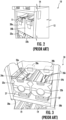
- a prior art product dispenser 10 in particular a dispenser for frozen food such as french fries or chicken nuggets, is shown.
- the product dispenser 10 includes a housing 12 with a refrigeration unit 14 located on top of the housing 12 as well as an access door 16 to the refrigerated portion of the product dispenser 10.
- Product receiving spaces 18 are located beneath the enclosed area and are configured to receive a receptacle, such as a fry basket 19, into which a metered amount of product is to be dispensed.
- hoppers 20a, 20b are located within the refrigerated area and are assembled on top of drum housings 22a, 22b. Frozen food product (indicated by arrow 11 in Fig. 2 ) can be loaded into the hoppers 20a, 20b for metered dispensing.
- rotatable drums 24a, 24b are located within the respective drum housings 22a, 22b.
- Flexible paddles or fins (these terms are used interchangeably herein) 26a, 26b are located on the rotatable drums 24a, 24b.
- Drive motors 28a, 28b are individually activatable to rotate the respective associated rotatable drum 24a, 24b in order to move product from the open bottom end of the desired associated hopper 20a, 20b into the respective drum housings 22a, 22b so that the product can drop down on to the respective weighing/dispensing assembly 30a, 30b.
- These are indicated in their respective positions in Figures 1 and 3 , and an exemplary arrangement is shown in detail in Figures 4 and 5 .
- Boots 27 shown in Fig. 3 guide the food product 11 from the open bottom of the drum housings 22a, 22b to the weighing/dispensing assemblies 30a, 30b.
- the weighing/dispensing assemblies 30a, 30b may each include a mounting plate 31 that is connected to the housing 12.
- a support assembly 44 is slidably connected to the mounting plate 31 for up and down movement.
- Rotatable shafts 34a, 34b are rotatably supported in the support assembly 44 and respective dump doors 32a, 32b are connected to the respective rotatable shafts 34a, 34b.
- a dump motor 36 is mounted on the support assembly 44 and includes a dump motor gear box 38 that is connected to an actuator arm 39 that, upon activation of the dump door motor 36, is rotated into contact with a first dump door drive lever 40a, which can be connected via a linkage arm 42 to a second dump door drive lever 40b in order to activate and open the dump doors 32a, 32b. This is done when a specific product weight is accumulated on the dump doors 32a, 32b based on rotation of an associated one of the rotatable drums 24a, 24b moving product from the bottom of a respective one of the hoppers 28a, 28b so it falls through the respective drum housing 22a, 22b, onto the respective closed dump doors 32a, 32b.
- a load cell 46 is provided and is in contact with the support assembly 44 as the food product is accumulated on the dump doors 32a, 32b while the rotatable drum 24a or 24b is rotated by the respective drive motor 28a or 28b.
- the load cell 46 detects that the desired amount of food product is located on the dump doors 32a, 32b, rotation of the rotatable drum 24a or 24b is stopped and the dump door motor 36 is activated in order to open the dump doors 32a, 32b.
- a support assembly lift motor 48 is provided and is connected to a support assembly lift gear box 50.
- the support assembly lift motor 48 is activated in order to raise the support assembly 44 out of contact with the load cell 46 when the dispensing cycle is completed so that the load cell 46 is not loaded until a next dispensing cycle is initiated and the support assembly lift motor is activated to move the support assembly 44 into contact with the load cell 46.
- the product dispenser 110 is similar to the product dispenser 10 and includes the housing 12, refrigeration unit 14 as well as the access door 16 and fry basket receiving spaces 18 in which fry baskets or other receptacles 19 for dispensed product can be positioned, as described above. Additionally, the hoppers 20a, 20b as well as the drum housings 22a, 22b and rotatable drums 24a, 24b are provided as described above in connection with the product dispenser 10.
- Drive motors 28a, 28b as described above for driving the rotatable drums 24a, 24b are also provided and are used to drive the respective rotatable drums 24a, 24b to engage with and move food product from the open bottom of a respective hopper 20a or 20b to a position in the drum housing 22a, 22b where the food product can then fall through the open bottom of the drum housing 22a, 22b.
- weighing/dispensing assemblies 30a, 30b are used as described above to receive and weigh the product to be dispensed.
- weighing/dispensing assemblies could be utilized that include at least a load cell to determine a weight of product being accumulated prior to being dispensed, and a dispensing mechanism which can include, for example, one or more dump doors, a tilt tray, a sweep arm or any other means for moving product off of the weighing assembly and into the receptacle for the dispensed product.
- a dispensing mechanism which can include, for example, one or more dump doors, a tilt tray, a sweep arm or any other means for moving product off of the weighing assembly and into the receptacle for the dispensed product.
- the product dispenser 110 is also described with two dispensing arrangements similar to that shown in Figure 1 , it could also be a dispensing arrangement (one hopper, one rotatable drum, and one weighing/dispensing mechanism) or include more than two dispensing arrangements.
- the product dispenser 110 includes a controller 170, preferably including a processor and memory, that is programmed and configured to: a) actuate the drive motor 28a or 29b to rotate the rotatable drum 24a or 24b at a start of a dispensing cycle, b) receive a signal from the load cell 46 and determine a weight of the product accumulating on the one or more dump doors 32a, 32b, c) determine if a percentage of a product weight target preset value is reached for the product accumulating on the dump doors 32a, 32b, d) upon the product weight target preset value being reached, starting a pulsing algorithm including sending alternating run and pause signals to the drive motor 28a or 28b, e) determine if a target weight is reached based on the signal from the load cell 46 of the weight of the product accumulating on the one or more dump doors 32a, 32b, f) deactivate the drive motor 28a or 28b upon the target weight being detected, and
- the product weight target present value can become for example, 80% of the target weight of 32 ounces
- the pulsing algorithm can include, for example, an alternating run time of 150 ms for the drive motor 28a or 28b and an off time of 150 ms for the drive motor28a, 28b. This provides a pulsing that is equivalent to about 50% of the rated speed of the motor 28a or 28b and allows for more accuracy in achieving the target product weight for the dispensed product on the one or more dump doors 32a, 32b prior to deactivating the drive motor 28a or 28b.
- Achieving the target weight is understood as being within a certain tolerance of the preset target weight, and is preferably within 5% and more preferably within 2%.
- the product weight target preset value is noted as 80% of the actual target weight. However, this could be varied, and it could be 85% or 90%.
- the pulsing algorithm can include, for example, an alternating 200 ms run time and a 100 ms off time.
- this algorithm can be varied depending upon the product density and configuration.
- this algorithm by programming it into the controller 170, it is possible to run the drive motor 28a or 28b at full speed up until the product weight target preset value is reached at which point the pulsing algorithm is engaged in order to provide higher accuracy at meeting the target weight of dispensed product onto the dump doors 32a, 32b.
- this can be achieved within 5% and more preferably within 2% of the desired target weight in a rapid manner. Depending on the particular application, this could optimally be within 1%.
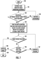
- the controller 170 is further configured to detect a total dispense time, which is indicated at 186 in the controller logic diagram provided in Figure 7 .
- the controller 170 can be further configured to signal a display 160 if a dispensed total time preset value is exceeded. This can be, for example, 15 seconds from a start of a dispensing cycle. If this time is exceeded, this may indicate that product may have bridged or jammed at the storage hopper dispensing opening above the rotatable drum 24a, 24b or could also indicate that the storage hopper is empty.
- the controller 170 can be configured to continue the pulsing algorithm, including sending alternating run and pause signals to the drive motor 28a or 28b, if the target weight is not reached and the total dispense time is not exceeded. This is illustrated, for example at 185, 186 and 187 of the logic flow diagram for the controller 170 shown in Figure 7 .
- the product dispenser 110 includes a housing 12, similar to that discussed above, as well as a refrigeration unit 14 for cooling an interior space of the housing 12, and the hopper 20a, 20b as well as the rotatable drums 24a, 24b is located in the housing 12. This is particularly useful for dispensing frozen food products where the product dispenser 110 is a frozen food dispenser.
- the controller 170 is configured to independently control the dispensing of product from each of the storage hoppers 20a, 20b.
- a receptacle sensor 162 that is configured to detect a receptacle 19 being placed into a receiving space 18 under the one or more dump doors 32a, 32b is provided.
- the receptacle sensor 162 signals the controller 170 which is configured to initiate the dispensing cycle upon the receptacle 19 being detected.
- the sensor 162 can be, for example, a proximity sensor, break beam sensor, or any other suitable type of sensor that detects the presence of a receptacle in a specific area beneath the one or more dump doors 32a, 32b for each dispensing arrangement.
- controller 170 an exemplary logic flow for the controller 170 is shown in connection with dispensing from one storage hopper 20a of one dispensing arrangement.
- the controller 170 can also have multiple algorithms associated with different ones of the storage hoppers 20a, 20b of different dispensing arrangements to the extent that different product is being dispensed and different pulsing algorithms are utilized.
- the controller 170 starts a dispensing cycle, as indicated at 180, which can be done via a signal from a receptacle sensor 162, or can be manually activated, for example by a start button being pressed by a user. This includes activating the drive motor 28a or 28b to rotate the rotatable drum 24a or 24b. As shown at 181, once the dispensing cycle has initiated, the controller 170 monitors the target percentage dispensed based on signals received from the load cell 46 in order to determine whether a product weight target preset value has been reached.
- the pulsing algorithm is started as indicated at 184. In the event that the percentage of product weight target preset value is not reached, dispensing continues as indicated at 183.
- the controller 170 continues the run and pause cycle based on the preset values for the product specific algorithm in order to allow an accurate weight to accumulate such that the product weight equals the target weight within a specific margin, for example 5% of the target weight, and more specifically, 2% of the target weight.
- the controller 170 signals the display 160 that the dispensed product is "ready” and deactivates the drive motor 28a or 28b so that no additional product is removed from the hopper 20a or 20b.
- the controller 170 continues the pulsing algorithm to the drive motor 28a or 28b as indicated at 187.
- the controller 170 can also determine whether or not a dispense total time has been reached and if in fact this has been reached, the controller 170 deactivates the drive motor 28a or 28b and discontinues the pulsing cycle and also signals the display 160. To the extent that the total time has not been reached, the controller 170 continues the pulsing algorithm signal to the drive motor 28a or 28b as indicated at 187 until the target weight is reached or the total time is reached as indicated at 185 and 186. Once the dispensing cycle is completed as indicated at 189, the product on the weighing/dispensing mechanism 30a or 30b is dropped and/or released into the receptacle 19 and the dispensing program ends.
Landscapes
- Physics & Mathematics (AREA)
- General Physics & Mathematics (AREA)
- Engineering & Computer Science (AREA)
- Food Science & Technology (AREA)
- Mechanical Engineering (AREA)
- Life Sciences & Earth Sciences (AREA)
- Weight Measurement For Supplying Or Discharging Of Specified Amounts Of Material (AREA)
Applications Claiming Priority (1)
| Application Number | Priority Date | Filing Date | Title |
|---|---|---|---|
| US202263420783P | 2022-10-31 | 2022-10-31 |
Publications (1)
| Publication Number | Publication Date |
|---|---|
| EP4361981A1 true EP4361981A1 (de) | 2024-05-01 |
Family
ID=88297021
Family Applications (1)
| Application Number | Title | Priority Date | Filing Date |
|---|---|---|---|
| EP23202294.7A Pending EP4361981A1 (de) | 2022-10-31 | 2023-10-09 | Spender für abgemessene nahrungsmittel mit genauigkeitspulsierung für verbesserte ausgabegenauigkeit |
Country Status (5)
| Country | Link |
|---|---|
| US (1) | US20240138621A1 (de) |
| EP (1) | EP4361981A1 (de) |
| JP (1) | JP2024066447A (de) |
| CN (1) | CN117945181A (de) |
| MX (1) | MX2023012752A (de) |
Families Citing this family (1)
| Publication number | Priority date | Publication date | Assignee | Title |
|---|---|---|---|---|
| WO2026140152A1 (ja) * | 2024-12-26 | 2026-07-02 | 株式会社寺岡精工 | 計量装置 |
Citations (3)
| Publication number | Priority date | Publication date | Assignee | Title |
|---|---|---|---|---|
| US20060113324A1 (en) * | 2004-11-30 | 2006-06-01 | Niro-Plan Ag | Multi-product dispenser and method of using same |
| US20110101022A1 (en) * | 2007-02-15 | 2011-05-05 | Automated Equipment Llc | Dual hopper frozen dispenser |
| US20140001199A1 (en) * | 2010-07-28 | 2014-01-02 | Steven Bruck | Bulk vending apparatus, system and method |
-
2023
- 2023-09-05 JP JP2023143347A patent/JP2024066447A/ja active Pending
- 2023-10-05 US US18/481,389 patent/US20240138621A1/en active Pending
- 2023-10-09 EP EP23202294.7A patent/EP4361981A1/de active Pending
- 2023-10-26 MX MX2023012752A patent/MX2023012752A/es unknown
- 2023-10-31 CN CN202311438670.7A patent/CN117945181A/zh active Pending
Patent Citations (3)
| Publication number | Priority date | Publication date | Assignee | Title |
|---|---|---|---|---|
| US20060113324A1 (en) * | 2004-11-30 | 2006-06-01 | Niro-Plan Ag | Multi-product dispenser and method of using same |
| US20110101022A1 (en) * | 2007-02-15 | 2011-05-05 | Automated Equipment Llc | Dual hopper frozen dispenser |
| US20140001199A1 (en) * | 2010-07-28 | 2014-01-02 | Steven Bruck | Bulk vending apparatus, system and method |
Also Published As
| Publication number | Publication date |
|---|---|
| CN117945181A (zh) | 2024-04-30 |
| MX2023012752A (es) | 2024-05-13 |
| JP2024066447A (ja) | 2024-05-15 |
| US20240138621A1 (en) | 2024-05-02 |
Similar Documents
| Publication | Publication Date | Title |
|---|---|---|
| JP3108811B2 (ja) | フレンチフライディスペンサ機 | |
| US5244020A (en) | Dispenser | |
| EP4361980A1 (de) | Spender für abgemessene nahrungsmittel mit durch einen einzigen motor betätigten wiege- und ausgabemechanismen | |
| US11756368B2 (en) | Bulk product dispenser | |
| US20060113324A1 (en) | Multi-product dispenser and method of using same | |
| US20110151074A1 (en) | Automated food preparation apparatus and method | |
| US20240138621A1 (en) | Metered food dispenser with accuracy pulsing for improved dispensing accuracy | |
| CA2015743A1 (en) | Food processing apparatus | |
| US5385464A (en) | Apparatus for automatically dispensing food product such as hard ice cream | |
| JP4675297B2 (ja) | 食材等の材料自動計量装置 | |
| EP4361581A1 (de) | Lebensmitteldosierspender mit bidirektionaler ausgabetrommelbewegung zur reduzierung von produktbrücken | |
| US6401600B1 (en) | Device for preparing foodstuffs | |
| US20240206647A1 (en) | Bulk material dispensing system | |
| HK40107005A (en) | Product dispenser | |
| EP3324373A1 (de) | Spender zum kontinuierlichen versorgen von bratmaschinen | |
| HK40107004A (en) | Product dispenser | |
| HK40106051A (en) | Product dispenser | |
| EP4230100A1 (de) | Spender für frittiermaschinen, der einen einzigen motor aufweist | |
| GB2089648A (en) | Dispensing apparatus for cooked foods | |
| EP3324372A1 (de) | Spender zum zuführen einer frittiervorrichtung |
Legal Events
| Date | Code | Title | Description |
|---|---|---|---|
| PUAI | Public reference made under article 153(3) epc to a published international application that has entered the european phase |
Free format text: ORIGINAL CODE: 0009012 |
|
| STAA | Information on the status of an ep patent application or granted ep patent |
Free format text: STATUS: THE APPLICATION HAS BEEN PUBLISHED |
|
| AK | Designated contracting states |
Kind code of ref document: A1 Designated state(s): AL AT BE BG CH CY CZ DE DK EE ES FI FR GB GR HR HU IE IS IT LI LT LU LV MC ME MK MT NL NO PL PT RO RS SE SI SK SM TR |
|
| STAA | Information on the status of an ep patent application or granted ep patent |
Free format text: STATUS: REQUEST FOR EXAMINATION WAS MADE |
|
| 17P | Request for examination filed |
Effective date: 20241015 |
|
| RBV | Designated contracting states (corrected) |
Designated state(s): AL AT BE BG CH CY CZ DE DK EE ES FI FR GB GR HR HU IE IS IT LI LT LU LV MC ME MK MT NL NO PL PT RO RS SE SI SK SM TR |