EP4361439A1 - Method for manufacturing compressor - Google Patents
Method for manufacturing compressor Download PDFInfo
- Publication number
- EP4361439A1 EP4361439A1 EP22858135.1A EP22858135A EP4361439A1 EP 4361439 A1 EP4361439 A1 EP 4361439A1 EP 22858135 A EP22858135 A EP 22858135A EP 4361439 A1 EP4361439 A1 EP 4361439A1
- Authority
- EP
- European Patent Office
- Prior art keywords
- joining surface
- joining
- intermediate portion
- barrel
- stator core
- Prior art date
- Legal status (The legal status is an assumption and is not a legal conclusion. Google has not performed a legal analysis and makes no representation as to the accuracy of the status listed.)
- Pending
Links
Images






Classifications
-
- F—MECHANICAL ENGINEERING; LIGHTING; HEATING; WEAPONS; BLASTING
- F04—POSITIVE - DISPLACEMENT MACHINES FOR LIQUIDS; PUMPS FOR LIQUIDS OR ELASTIC FLUIDS
- F04B—POSITIVE-DISPLACEMENT MACHINES FOR LIQUIDS; PUMPS
- F04B35/00—Piston pumps specially adapted for elastic fluids and characterised by the driving means to their working members, or by combination with, or adaptation to, specific driving engines or motors, not otherwise provided for
- F04B35/04—Piston pumps specially adapted for elastic fluids and characterised by the driving means to their working members, or by combination with, or adaptation to, specific driving engines or motors, not otherwise provided for the means being electric
-
- F—MECHANICAL ENGINEERING; LIGHTING; HEATING; WEAPONS; BLASTING
- F04—POSITIVE - DISPLACEMENT MACHINES FOR LIQUIDS; PUMPS FOR LIQUIDS OR ELASTIC FLUIDS
- F04B—POSITIVE-DISPLACEMENT MACHINES FOR LIQUIDS; PUMPS
- F04B39/00—Component parts, details, or accessories, of pumps or pumping systems specially adapted for elastic fluids, not otherwise provided for in, or of interest apart from, groups F04B25/00 - F04B37/00
- F04B39/12—Casings; Cylinders; Cylinder heads; Fluid connections
- F04B39/121—Casings
-
- F—MECHANICAL ENGINEERING; LIGHTING; HEATING; WEAPONS; BLASTING
- F04—POSITIVE - DISPLACEMENT MACHINES FOR LIQUIDS; PUMPS FOR LIQUIDS OR ELASTIC FLUIDS
- F04B—POSITIVE-DISPLACEMENT MACHINES FOR LIQUIDS; PUMPS
- F04B39/00—Component parts, details, or accessories, of pumps or pumping systems specially adapted for elastic fluids, not otherwise provided for in, or of interest apart from, groups F04B25/00 - F04B37/00
- F04B39/14—Provisions for readily assembling or disassembling
-
- F—MECHANICAL ENGINEERING; LIGHTING; HEATING; WEAPONS; BLASTING
- F04—POSITIVE - DISPLACEMENT MACHINES FOR LIQUIDS; PUMPS FOR LIQUIDS OR ELASTIC FLUIDS
- F04C—ROTARY-PISTON, OR OSCILLATING-PISTON, POSITIVE-DISPLACEMENT MACHINES FOR LIQUIDS; ROTARY-PISTON, OR OSCILLATING-PISTON, POSITIVE-DISPLACEMENT PUMPS
- F04C23/00—Combinations of two or more pumps, each being of rotary-piston or oscillating-piston type, specially adapted for elastic fluids; Pumping installations specially adapted for elastic fluids; Multi-stage pumps specially adapted for elastic fluids
- F04C23/008—Hermetic pumps
-
- H—ELECTRICITY
- H02—GENERATION; CONVERSION OR DISTRIBUTION OF ELECTRIC POWER
- H02K—DYNAMO-ELECTRIC MACHINES
- H02K1/00—Details of the magnetic circuit
- H02K1/06—Details of the magnetic circuit characterised by the shape, form or construction
- H02K1/12—Stationary parts of the magnetic circuit
- H02K1/18—Means for mounting or fastening magnetic stationary parts on to, or to, the stator structures
-
- H—ELECTRICITY
- H02—GENERATION; CONVERSION OR DISTRIBUTION OF ELECTRIC POWER
- H02K—DYNAMO-ELECTRIC MACHINES
- H02K1/00—Details of the magnetic circuit
- H02K1/06—Details of the magnetic circuit characterised by the shape, form or construction
- H02K1/12—Stationary parts of the magnetic circuit
- H02K1/18—Means for mounting or fastening magnetic stationary parts on to, or to, the stator structures
- H02K1/185—Means for mounting or fastening magnetic stationary parts on to, or to, the stator structures to outer stators
-
- H—ELECTRICITY
- H02—GENERATION; CONVERSION OR DISTRIBUTION OF ELECTRIC POWER
- H02K—DYNAMO-ELECTRIC MACHINES
- H02K15/00—Processes or apparatus specially adapted for manufacturing, assembling, maintaining or repairing of dynamo-electric machines
- H02K15/12—Impregnating, moulding insulation, heating or drying of windings, stators, rotors or machines
-
- F—MECHANICAL ENGINEERING; LIGHTING; HEATING; WEAPONS; BLASTING
- F04—POSITIVE - DISPLACEMENT MACHINES FOR LIQUIDS; PUMPS FOR LIQUIDS OR ELASTIC FLUIDS
- F04C—ROTARY-PISTON, OR OSCILLATING-PISTON, POSITIVE-DISPLACEMENT MACHINES FOR LIQUIDS; ROTARY-PISTON, OR OSCILLATING-PISTON, POSITIVE-DISPLACEMENT PUMPS
- F04C18/00—Rotary-piston pumps specially adapted for elastic fluids
- F04C18/30—Rotary-piston pumps specially adapted for elastic fluids having the characteristics covered by two or more of groups F04C18/02, F04C18/08, F04C18/22, F04C18/24, F04C18/48, or having the characteristics covered by one of these groups together with some other type of movement between co-operating members
- F04C18/34—Rotary-piston pumps specially adapted for elastic fluids having the characteristics covered by two or more of groups F04C18/02, F04C18/08, F04C18/22, F04C18/24, F04C18/48, or having the characteristics covered by one of these groups together with some other type of movement between co-operating members having the movement defined in group F04C18/08 or F04C18/22 and relative reciprocation between the co-operating members
- F04C18/356—Rotary-piston pumps specially adapted for elastic fluids having the characteristics covered by two or more of groups F04C18/02, F04C18/08, F04C18/22, F04C18/24, F04C18/48, or having the characteristics covered by one of these groups together with some other type of movement between co-operating members having the movement defined in group F04C18/08 or F04C18/22 and relative reciprocation between the co-operating members with vanes reciprocating with respect to the outer member
-
- F—MECHANICAL ENGINEERING; LIGHTING; HEATING; WEAPONS; BLASTING
- F04—POSITIVE - DISPLACEMENT MACHINES FOR LIQUIDS; PUMPS FOR LIQUIDS OR ELASTIC FLUIDS
- F04C—ROTARY-PISTON, OR OSCILLATING-PISTON, POSITIVE-DISPLACEMENT MACHINES FOR LIQUIDS; ROTARY-PISTON, OR OSCILLATING-PISTON, POSITIVE-DISPLACEMENT PUMPS
- F04C2230/00—Manufacture
- F04C2230/60—Assembly methods
-
- F—MECHANICAL ENGINEERING; LIGHTING; HEATING; WEAPONS; BLASTING
- F04—POSITIVE - DISPLACEMENT MACHINES FOR LIQUIDS; PUMPS FOR LIQUIDS OR ELASTIC FLUIDS
- F04C—ROTARY-PISTON, OR OSCILLATING-PISTON, POSITIVE-DISPLACEMENT MACHINES FOR LIQUIDS; ROTARY-PISTON, OR OSCILLATING-PISTON, POSITIVE-DISPLACEMENT PUMPS
- F04C2240/00—Components
- F04C2240/40—Electric motor
Definitions
- the present disclosure relates to a method for manufacturing a compressor.
- a resin member which is a nonconductive material, is fixed to a space between a barrel of a casing and a stator core of an electric motor.
- Patent Document 1 Japanese Unexamined Patent Publication No. 2001-289173
- the resin member melts by heat of the barrel of the casing heated, which may cause protrusion of the resin member from a j oining surface between the barrel and the stator core by shrink fit pressure.
- Burrs of the resin member generated by the protrusion from the joining surface in this way may be detached during operation of the compressor and may enter the compression chamber or refrigerant pipe, which may cause a failure of the refrigeration apparatus.
- An object of the present disclosure is to reduce generation of burrs of the resin member.
- a first aspect is directed to a method for manufacturing a compressor (20) including a tubular barrel (22),
- the intermediate portion (74) of the first joining surface (71) comes into contact with the second joining surface (81) in the first step.
- the spaces (S) are formed on both sides of the intermediate portion (74), and thus are gradually filled with the melted resin member (60) from the intermediate portion (74) toward the first end (72) and the second end (73).
- the first joining surface (71) and the second joining surface (81) are joined to each other, and protrusion of the resin member from the spaces between the first joining surface (71) and the second joining surface (81) is reduced.
- generation of burrs of the resin member (60) can be reduced.
- a second aspect is an embodiment of the first aspect.
- the first end (72) and the second end (73) face each other in a circumferential direction of the barrel (22).
- the spaces (S) are formed in the circumferential direction of the barrel (22). This can reduce generation of burrs at the circumferential ends of the first joining surface (71) and the second joining surface (81).
- a third aspect is an embodiment of the first or second aspect.
- the first end (72) and the second end (73) face each other in an axial direction of the barrel (22).
- the spaces (S) are formed in the axial direction of the barrel (22). This can reduce generation of burrs at the axial ends of the first joining surface (71) and the second joining surface (81).
- a fourth aspect is an embodiment of any one of the first to third aspects. In the fourth aspect,
- the first curvature of the first curved surface (71a) is larger than the second curvature of the second joining surface (81).
- the intermediate portion (74) of the first curved surface (71a) comes into contact with the second joining surface (81) first when the first joining surface (71) and the second joining surface (81) come into contact with each other.
- a fifth aspect is an embodiment of any one of the first to fourth aspects.
- the fifth aspect is an embodiment of any one of the first to fourth aspects.
- a sixth aspect of the present disclosure is an embodiment of any one of the first to fifth aspects.
- the sixth aspect is an embodiment of any one of the first to fifth aspects.
- the intermediate portion (74) of the first joining surface (71) and the second joining surface (81) come into contact with each other, and thereafter, the melted resin member gradually fills the first recess (76a) and the second recess (76b) as the melted resin member flows from the intermediate portion (74) toward the first end (72) and the second end (73) and fills the spaces (S). This reduces generation of resin burrs.
- a seventh aspect is an embodiment of any one of the first to sixth aspects. In the seventh aspect,
- the spaces (S) are formed inside the groove (82). This reduces protrusion of the resin from the groove (82) even when shrink fit pressure is applied. As a result, generation of resin burrs can be reduced.
- An eighth aspect of the present disclosure is an embodiment of the seventh aspect. In the eighth aspect,
- the plane structure (C) allows spaces (S) to be formed inside the groove (82) upon contact of the intermediate portion (74) with the second protrusion (83). This allows reduction in protrusion of the melted resin member (60) from the groove (82).
- a ninth aspect is an embodiment of the eighth aspect.
- the plane structure (C) has a third recess into which the second protrusion (83) is fitted in the first step.
- the second protrusion (83) is fitted in the third recess (77), so that the resin member (60) can be fixed to a space inside the groove (82). This substantially prevents the resin member (60) from being displaced from the groove (82).
- a tenth aspect is an embodiment of the eighth aspect.
- the plane structure (C) includes a third curved surface (71c) having a third curvature centered around a point outside the stator core (32).
- the third curved surface (71c) allows the first end (72) and the second end (73) to be placed inside the groove (82) when the intermediate portion (74) comes into contact with the second protrusion (83) in the first step. This allows formation of spaces (S) inside the groove (82).
- a compressor (20) of the present disclosure is provided for a refrigeration apparatus (1).
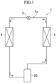
- the refrigeration apparatus (1) shown in FIG. 1 includes the compressor (20) of the present disclosure.
- the refrigeration apparatus (1) has a refrigerant circuit (1a) filled with a refrigerant.
- the refrigerant circuit (1a) has a compressor (20), a radiator (2), a decompression mechanism (3), and an evaporator (4).
- the decompression mechanism (3) is an expansion valve.
- the refrigerant circuit (1a) performs a vapor compression refrigeration cycle.
- the refrigerant compressed by the compressor (20) dissipates heat to the air in the radiator (2).
- the refrigerant which has dissipated heat is decompressed by the decompression mechanism (3) and evaporates in the evaporator (4).
- the refrigerant which has evaporated is sucked into the compressor (20).
- the refrigeration apparatus (1) is an air conditioner.
- the air conditioner may be any of a cooling-only apparatus, a heating-only apparatus, or an air conditioner which switches between cooling and heating. In such a case, the air conditioner has a switching mechanism (e.g., a four-way switching valve) which switches a direction in which the refrigerant circulates.
- the refrigeration apparatus (1) may be a water heater, a chiller unit, or a cooling apparatus which cools the air in an internal space.
- the cooling apparatus cools the air in an internal space of a refrigerator, a freezer, a container, or the like.
- the expansion mechanism is an electronic expansion valve, a temperature-sensitive expansion valve, an expander, or a capillary tube.
- the compressor (20) is a rotary fluid machinery.
- the compressor (20) has a casing (21), an electric motor (30), a drive shaft (28), and a compression mechanism (50).
- the casing (21) houses the electric motor (30), the drive shaft (28), and the compression mechanism (50).
- the casing (21) is a hermetic container.
- the inside of the casing (21) is filled with a high-pressure refrigerant discharged from the compression mechanism (50).
- the casing (21) is made of a metal material.
- the casing (21) has a barrel (22), a bottom portion (23), and a top portion (24).
- the barrel (22) is a cylindrical metal member. At each of both ends of the barrel (22) in the axial direction, an opening is formed. In this example, the axial direction of the barrel (22) corresponds to the vertical direction.
- the bottom portion (23) closes the lower opening of the barrel (22).
- the top portion (24) closes the upper opening of the barrel (22).
- the electric motor (30) is arranged above the compression mechanism (50).
- the electric motor (30) has a stator (31) and a rotor (40).
- the stator (31) is supported by the barrel (22) of the casing (21).
- the fixing structure for the stator (31) will be described in detail later.
- the stator (31) has a stator core (32) and a coil (33) wound around the stator core (32).
- the stator core (32) includes electrical steel sheets stacked in the axial direction. As illustrated in FIG. 3 , the stator core (32) has an annular back yoke (34) and a plurality of (six in this example) teeth (35) extending radially inward from the inner peripheral surface of the back yoke (34).
- the outer peripheral surface of the back yoke (34) has a plurality of (six in this example) core cuts (36).
- the core cuts (36) are grooves extending in the axial direction of the stator core (32).
- a protrusion (37) protruding radially outward is provided between adjacent core cuts (36).
- the stator core (32) of the present example is provided with six protrusions (37).
- Each of the protrusions (37) has a pair of side surfaces (37a) extending radially outward and an end surface (37b) provided between the side surfaces (37a) in pair.
- the protrusion (37) extends toward both ends in the axial direction of the stator core (32).
- the rotor (40) is arranged inside the stator core (32).
- the drive shaft (28) is fixed in the axial center of the rotor (40).
- the rotor (40) is provided with a plurality of (four in this example) slots (41). A permanent magnet is embedded inside each of the slots (41).
- the operation frequency of the electric motor (30) is controlled by an inverter device.
- the compressor (20) is an inverter compressor having a variable operation frequency.
- the drive shaft (28) extends vertically along the axial center of the casing (21).
- the drive shaft (28) is rotated by the electric motor (30).
- the drive shaft (28) is rotatably supported by a bearing (29).
- the compression mechanism (50) has a cylinder (51) and a piston (52) provided inside the cylinder (51).
- a cylinder chamber (53) is formed between the inner peripheral surface of the cylinder (51) and the outer peripheral surface of the piston (52).
- a fluid is compressed by the piston (52) driven by the drive shaft (28).
- the compressor (20) has a suction pipe (45) and a discharge pipe (46).
- the suction pipe (45) penetrates the barrel (22) in the radial direction and communicates with the cylinder chamber (53).
- a low-pressure refrigerant in the refrigerant circuit (1a) is sucked into the cylinder chamber (53) through the suction pipe (45).
- the discharge pipe (46) penetrates the top portion (24) in the axial direction and communicates with an internal space of the casing (21).
- the refrigerant compressed in the compression mechanism (50) flows through portions, such as the core cuts (36) of the electric motor (30), and is then sent to the refrigerant circuit (1a) through the discharge pipe (46).
- the compressor (20) of the present embodiment has resin members (60) provided on the outer peripheral surface of the stator core (32).
- the compressor (20) has resin members (60).
- the resin members (60) are located at the respective positions corresponding to the protrusions (37) of the stator core (32).
- the number of resin members (60) is the same as the number of protrusions (37).
- eight protrusions (37) may be provided for the outer peripheral surface of the stator core (32).
- the compressor (20) has eight resin members (60) corresponding to the respective protrusions (37).
- Each of the resin members (60) is made of an insulating material.
- the resin member (60) has a function of reducing propagation of electromagnetic noise of the electric motor (30) to the outside of the casing (21).
- the resin member (60) is made of, for example, polyphenylene sulfide (PPS).
- PPS polyphenylene sulfide
- the resin member (60) may be a liquid crystal polymer (LCP).
- LCP liquid crystal polymer
- the resin member (60) may be a composite material in which PPS contains glass fibers.
- the resin member (60) is fixed to the outer peripheral surface of the stator core (32).
- the resin member (60) extends toward both ends of the stator core (32) in the axial direction.
- the resin member (60) covers the entire surface of the protrusion (37) of the stator core (32).
- the resin member (60) is made of a pair of bases (61), a pair of sidewalls (62), and a fixing portion (63) that are combined together.
- the bases (61) in pair are provided on both sides of the base of the protrusion (37) on the outer peripheral surface of the back yoke (34).
- the bases (61) in pair extend along the outer peripheral surface of the back yoke (34).
- Each of the sidewalls (62) in pair covers an associated side surface (37a) of the protrusion (37).
- the sidewalls (62) in pair extend in the direction in which the protrusion (37) protrudes.
- the fixing portion (63) is continuous with radially outer ends of the sidewalls (62) in pair.
- the fixing portion (63) is arc-shaped along the inner peripheral surface of the barrel (22) in a cross section perpendicular to the axial direction of the barrel (22).
- the fixing portion (63) is located between the barrel (22) and the stator core (32).
- the resin member (60) is formed on the outer peripheral surface of the stator core (32) by insert molding.
- the method for manufacturing the compressor (20) will be described in detail below with reference to FIGS. 5 to 7 .
- the method for manufacturing a compressor (20) includes shrink fitting of fixing the stator core (32) to the inside of the barrel (22) via the resin members (60) by shrink fit.
- the shrink fitting includes: insert molding, heating, and joining.
- the resin members (60) are formed on the outer peripheral surface of the stator core (32) by insert molding to obtain a unit (U).
- the insert molding allows the resin members (60) to be easily formed on the outer peripheral surface of the stator core (32).
- the shape of the outer peripheral surface of the fixing portion (63) of the resin member (60) formed on the outer peripheral surface of the stator core (32) will be described in detail below with reference to FIG. 6 .
- the outer peripheral surface of the fixing portion (63) is a first joining surface (71) of the present disclosure.
- the first joining surface (71) has a first end (72) and a second end (73) facing each other.
- the first end (72) and the second end (73) face each other in the circumferential direction of the stator core (32).
- the first end (72) and the second end (73) are portions at which the fixing portion (63) is connected to the sidewalls (62).
- FIG. 6 shows a portion of the barrel (22) for description of the first joining surface (71).
- the first joining surface (71) is arc-shaped when viewed from above the stator core (32).
- the first joining surface (71) is arc-shaped in the circumferential direction of the stator core (32).
- the first joining surface (71) has a first curved surface (71a) having a first curvature 1/r 1 .
- the first curved surface (71a) is formed on the entire first joining surface (71).
- the first curved surface (71a) may be formed on a part of the first joining surface (71).
- the r 1 is a curvature radius of the first curved surface (71a) centered around O 1 .
- the r 1 is smaller than the radius of the stator core (32).
- a portion of the first joining surface (71) located at a center between the first end (72) and the second end (73) is an intermediate portion (74).
- the intermediate portion (74) is located at the outermost position of the first joining surface (71) in the radial direction of the stator core (32). In the circumferential direction of the first joining surface (71), the distance between the intermediate portion (74) and the first end (72) is substantially equal to the distance between the intermediate portion (74) and the second end (73).
- the first curved surface (71a) is formed in the intermediate portion (74) of the first joining surface (71) when formed in a part of the first joining surface (71).
- a portion of the inner peripheral surface of the barrel (22) in contact with the first joining surface (71) in the joining is a second joining surface (81).
- the second joining surface (81) has a second curvature 1/r 2 .
- the r 2 is a curvature radius of the second joining surface (81) centered around O 2 .
- O 2 coincides with the axial center of the barrel (22).
- the r 2 is equal to the radius of the barrel (22).
- the first curvature 1/r 1 is larger than the second curvature 1/rz of the second joining surface (81).
- a tubular barrel (22) in the state in which the top portion (24) and the bottom portion (23) of the casing (21) are not fixed is used.
- the barrel (22) of the casing (21) is heated. This causes thermal expansion of the barrel (22), and the diameters (the inner diameter and the outer diameter) of the barrel (22) increase.
- the joining is a first step of the present disclosure.
- an operator inserts the unit (U) into the barrel (22).
- the heating makes the diameter of the barrel (22) increase, so that the unit (U) is easily inserted into the barrel (22).
- the inner diameter of the barrel (22) is reduced, so that the unit (U) is fitted into the barrel (22).
- the unit (U) is fixed to the inside of the barrel (22) by shrink fit.
- the process of joining the first joining surface (71) to the second joining surface (81) will be described below with reference to FIG. 9 .
- the intermediate portion (74) of the first joining surface (71) of the resin member (60) comes into contact with the second joining surface (81) ( FIG. 9A ).
- spaces (S) are formed between the first joining surface (71) and the second joining surface (81) when the unit (U) and the barrel (22) are viewed from above.
- the spaces (S) are formed between the first end (72) and the intermediate portion (74) and between the second end (73) and the intermediate portion (74).
- the resin member (60) is first melted in the intermediate portion (74), and then gradually melted from the intermediate portion (74) toward the first end (72) and the second end (73) in the circumferential direction ( FIG. 9B ). Thereafter, the inner diameter of the barrel (22) decreases, so that the resin member (60) is gradually melted toward the first end (72) and the second end (73). Thus, the spaces (S) are gradually filled with the melted resin member (60). In this way, the joining area between the first joining surface (71) and the second joining surface (81) gradually increases, and eventually, the entire surface of the first joining surface (71) is joined to the second joining surface (81).
- the entire surface of the first joining surface (71) comes into contact with the second joining surface (81) all at once during the process of reducing the inner diameter of the barrel (22). Then, the resin member (60) on the entire surface of the first joining surface (71) melts, and the resin member (60) melted in the vicinities of the first end (72) and the second end (73) protrude from the first joining surface (71) and the second joining surface (81), thereby forming burrs.
- the melted resin member (60) flows toward the first end (72) and the second end (73) so as to gradually fill the spaces (S) therewith, thereby reducing protrusion of the resin member (60) from the first joining surface (71) and the second joining surface (81) ( FIG. 9C ).
- generation of burrs of the resin member (60) can be securely reduced.
- spaces (S) are formed between the first joining surface (71) and the second joining surface (81) upon contact of the intermediate portion (74) of the first joining surface (71) of the resin member (60) with the second joining surface (81) on the inner peripheral surface of the barrel (22).
- the spaces (S) are formed between the first end (72) and the intermediate portion (74) in the first joining surface (71) and between the second end (73) and the intermediate portion (74) in the first joining surface (71).
- the spaces (S) are formed on both sides of the intermediate portion (74), and thus, the spaces (S) are gradually filled with the melted resin member (60) from the intermediate portion (74) toward the first end (72) and the second end (73).
- generation of burrs of the protruded resin member (60) can be reduced, and failures in the compressor (20) and the refrigeration apparatus (1) including the compressor (20) can be reduced.
- the first end (72) and the second end (73) in the first joining surface (71) face each other in the circumferential direction of the stator core (32). This reduces protrusion of the resin member (60) in the circumferential direction of the first joining surface (71) and the second joining surface (81).
- the first joining surface (71) has a first curved surface (71a) having a first curvature.
- the first curvature is larger than a second curvature of the second joining surface (81). This allows the intermediate portion (74) of the first curved surface (71a) to first come into contact with the second joining surface (81), thereby forming spaces (S).
- the resin member (60) insert-molded in this variation is formed such that the vertical cross section of the first joining surface (71) is arc-shaped.
- the first joining surface (71) of this variation is arc-shaped in the axial direction of the barrel (22).
- the first end (72) and the second end (73) face each other in the axial direction of the stator core (32).
- the first end (72) is located at the upper end of the first joining surface (71)
- the second end (73) is located at the lower end of the first joining surface (71).
- the intermediate portion (74) is located between the first end (72) and the second end (73).
- the intermediate portion (74) extends in the circumferential direction of the first joining surface (71).
- the first end (72) and the second end (73) may be provided in the circumferential direction as well as in the top-bottom direction of the first joining surface (71).
- the intermediate portion (74) is located at the center of the first joining surface (71).
- the first joining surface (71) of this variation has a first convex portion (75) protruding radially outward of the stator core (32).
- the first convex portion (75) is located at a center portion of the first joining surface (71) in the circumferential direction and extends in the top-bottom direction of the first joining surface (71).
- the intermediate portion (74) is located at the distal end of the first convex portion (75).
- the first joining surface (71) of this variation has a first curvature 1/r 1 larger than a second curvature 1/r 2 as in the embodiment.
- the first joining surface (71) of this variation has a first recess (76a) and a second recess (76b).
- the first recess (76a) is formed between the first end (72) and the intermediate portion (74).
- the second recess (76b) is formed between the second end (73) and the intermediate portion (74).
- the first recess (76a) and the second recess (76b) extend in the top-bottom direction of the first joining surface (71).
- the first joining surface (71) of this variation has a first curvature 1/r 1 larger than a second curvature 1/r 2 as in the embodiment.
- the inner peripheral surface of the barrel (22) of this variation has a groove (82) recessed radially outward.
- the second joining surface (81) of this variation is a bottom surface of the groove (82).
- the groove (82) extends in the axial direction (the top-bottom direction) of the barrel (22).
- the first joining surface (71) has a first curvature 1/r 1 larger than a second curvature 1/r 2 as in the embodiment.
- a space (S) is formed on each side of the intermediate portion (74) in the circumferential direction ( FIG. 13B ).
- the melted resin member (60) fills the spaces (S) toward the first end (72) and the second end (73) as the inner diameter of the barrel (22) decreases.
- the first end (72) and the second end (73) come into contact with the second joining surface (81) inside the groove (82), thereby reducing protrusion of the melted resin member (60) from the groove (82) ( FIG. 13C ). This reduces generation of burrs of the resin member (60).
- the inner peripheral surface of the barrel (22) of this variation has grooves (82) recessed radially outward as in Fourth Variation.
- a second protrusion (83) protruding radially inward of the barrel (22) is formed in the grooves (82).
- the second joining surface (81) of this variation includes the bottom surfaces of the grooves (82) and the second protrusion (83).
- the first joining surface (71) of this variation has a plane structure (C).
- the plane structure (C) is formed during insert molding. Due to the plane structure (C), spaces (S) are formed in the grooves (82) upon contact of the intermediate portion (74) with the second protrusion (83) in the joining.
- the plane structure (C) of this variation includes a third recess (77).
- the third recess (77) is formed such that the second protrusion (83) is fitted into the third recess (77) during joining.
- the third recess (77) extends in the top-bottom direction.
- the third recess (77) is located between the first end (72) and the second end (73).
- the intermediate portion (74) is located inside the third recess (77).
- the first joining surface (71) of this variation has a curved surface having a first curvature similar to that in the embodiment and the third recess (77). The curved surface having the first curvature and the third recess (77) are formed during the insert molding.
- the second protrusion (83) of the second joining surface (81) is fitted into the third recess (77) of the first joining surface (71) ( FIG. 14B ).
- the intermediate portion (74) of this variation is the inner surface of the third recess (77). This allows formation of spaces (S) inside the grooves (82).
- the melted resin member (60) fills the spaces (S) toward the first end (72) and the second end (73) as the inner diameter of the barrel (22) decreases.
- the spaces (S) are formed inside the grooves (82). This reduces protrusion of the melted resin member (60) from the grooves (82).
- the second protrusion (83) is fitted into the third recess (77).
- the second joining surface (81) has the grooves (82) and the second protrusion (83). This increases the fixing force to the resin member (60) as compared with the case in which the second joining surface (81) is flat. This substantially prevents the stator core (32) from being displaced inside the barrel (22) even when the rotor (40) is driven.
- the plane structure (C) of this variation is a third curved surface (71c) having a third curvature 1/r 3 as viewed from above the stator core (32).
- the center of curvature of the third curvature 1/r 3 is located outside the stator core (32).
- the third curved surface (71c) of this variation is formed on the entire first joining surface (71).
- r 3 is a curvature radius of the first joining surface (71) of this variation.
- the third curved surface (71c) may be formed in a part of the first joining surface (71). In the joining, the first joining surface (71) is set to come into contact with the second protrusion (83), and the first end (72) and the second end (73) are set to come into contact with the second joining surface (81).
- first joining surface (71) comes into contact with both ends of the top portion of the second protrusion (83).
- first joining surface (71) in contact with both ends of the top portion are intermediate portions (74).
- Spaces (S) are formed between the intermediate portion (74) and the first end (72) and between the intermediate portion (74) and the second end (73).
- the spaces (S) are filled with the resin member (60) as the inner diameter of the barrel (22) decreases. Since the spaces (S) are formed inside the grooves (82), and the first end (72) and the second end (73) are in contact with the bottom surfaces of the grooves (82) (the second joining surface (81)), protrusion of the melted resin member (60) from the grooves (82) is reduced ( FIG. 15C ).
- the embodiment and variations may also be configured as follows.
- the intermediate portion (74) only needs to be located between the first end (72) and the second end (73), and needs not to be centered between the first end (72) and the second end (73).
- the first joining surface (71) may have a radius which is equal to the first curvature radius r 2 .
- the bottom surface of the groove (82) (the second joining surface (81)) needs not to be flat.
- the second curvature of the second joining surface (81) only needs to be smaller than the first curvature.
- the present disclosure is useful for a method for manufacturing a compressor.
Landscapes
- Engineering & Computer Science (AREA)
- Power Engineering (AREA)
- Mechanical Engineering (AREA)
- General Engineering & Computer Science (AREA)
- Manufacturing & Machinery (AREA)
- Compressor (AREA)
- Applications Or Details Of Rotary Compressors (AREA)
- Manufacture Of Motors, Generators (AREA)
Abstract
Description
- The present disclosure relates to a method for manufacturing a compressor.
- In the compressor described in Patent Document 1, a resin member, which is a nonconductive material, is fixed to a space between a barrel of a casing and a stator core of an electric motor.
- Patent Document 1:
Japanese Unexamined Patent Publication No. 2001-289173 - In the method in which the resin member is fixed to a space between the barrel of the casing and the stator core by shrink fit, the resin member melts by heat of the barrel of the casing heated, which may cause protrusion of the resin member from a j oining surface between the barrel and the stator core by shrink fit pressure.
- Burrs of the resin member generated by the protrusion from the joining surface in this way may be detached during operation of the compressor and may enter the compression chamber or refrigerant pipe, which may cause a failure of the refrigeration apparatus.
- An object of the present disclosure is to reduce generation of burrs of the resin member.
- A first aspect is directed to a method for manufacturing a compressor (20) including a tubular barrel (22),
- a stator core (32), and
- a resin member (60) provided on an outer peripheral surface of the stator core (32), the method including:
- fixing the stator core (32) to an inside of the barrel (22) via the resin member (60) by shrink fit, wherein
- when an outer peripheral surface of the resin member (60) is a first joining surface (71) and a surface in contact with the first joining surface (71) on an inner peripheral surface of the barrel (22) is a second joining surface (81), the fixing includes:
- a first step of joining the first joining surface (71) to the second joining surface (81), and in the first step,
- upon joining, to the second joining surface (81), an intermediate portion (74) of the first joining surface (71) between a first end (72) and a second end (73) facing each other, spaces (S) between the first joining surface (71) and the second joining surface (81) are formed between the first end (72) and the intermediate portion (74) and between the second end (73) and the intermediate portion (74).
- In the first aspect, first, the intermediate portion (74) of the first joining surface (71) comes into contact with the second joining surface (81) in the first step. At this time, the spaces (S) are formed on both sides of the intermediate portion (74), and thus are gradually filled with the melted resin member (60) from the intermediate portion (74) toward the first end (72) and the second end (73). In this way, the first joining surface (71) and the second joining surface (81) are joined to each other, and protrusion of the resin member from the spaces between the first joining surface (71) and the second joining surface (81) is reduced. As a result, generation of burrs of the resin member (60) can be reduced.
- A second aspect is an embodiment of the first aspect. In the second aspect,
the first end (72) and the second end (73) face each other in a circumferential direction of the barrel (22). - In the second aspect, the spaces (S) are formed in the circumferential direction of the barrel (22). This can reduce generation of burrs at the circumferential ends of the first joining surface (71) and the second joining surface (81).
- A third aspect is an embodiment of the first or second aspect. In the third aspect,
the first end (72) and the second end (73) face each other in an axial direction of the barrel (22). - In the third aspect, the spaces (S) are formed in the axial direction of the barrel (22). This can reduce generation of burrs at the axial ends of the first joining surface (71) and the second joining surface (81).
- A fourth aspect is an embodiment of any one of the first to third aspects. In the fourth aspect,
- the first joining surface (71) has a first curved surface (71a) having a first curvature,
- the intermediate portion (74) is located in the first curved surface (71a), and
- the first curvature is larger than a second curvature of the second joining surface (81).
- In the fourth aspect, the first curvature of the first curved surface (71a) is larger than the second curvature of the second joining surface (81). Thus, of the first joining surface (71), the intermediate portion (74) of the first curved surface (71a) comes into contact with the second joining surface (81) first when the first joining surface (71) and the second joining surface (81) come into contact with each other. This forms spaces (S) at both ends of the intermediate portion (74).
- A fifth aspect is an embodiment of any one of the first to fourth aspects. In the fifth aspect,
- the first joining surface (71) has a first convex portion (75) protruding radially outward of the stator core (32), and
- the intermediate portion (74) is located in the first convex portion (75).
- In the fifth aspect, when the first joining surface (71) and the second joining surface (81) come into contact with each other, the first convex portion (75) first comes into contact with the second joining surface (81). This forms spaces (S) at both ends of the first convex portion (75).
- A sixth aspect of the present disclosure is an embodiment of any one of the first to fifth aspects. In the sixth aspect,
- the first joining surface (71) has
- a first recess (76a) formed between the first end (72) and the intermediate portion (74), and
- a second recess (76b) formed between the second end (73) and the intermediate portion (74).
- In the sixth aspect, the intermediate portion (74) of the first joining surface (71) and the second joining surface (81) come into contact with each other, and thereafter, the melted resin member gradually fills the first recess (76a) and the second recess (76b) as the melted resin member flows from the intermediate portion (74) toward the first end (72) and the second end (73) and fills the spaces (S). This reduces generation of resin burrs.
- A seventh aspect is an embodiment of any one of the first to sixth aspects. In the seventh aspect,
- the inner peripheral surface of the barrel (22) has a groove (82) recessed radially outward, and
- the second joining surface (81) is a bottom surface of the groove (82).
- In the seventh aspect, when the intermediate portion (74) of the first joining surface (71) comes into contact with the second joining surface (81), the spaces (S) are formed inside the groove (82). This reduces protrusion of the resin from the groove (82) even when shrink fit pressure is applied. As a result, generation of resin burrs can be reduced.
- An eighth aspect of the present disclosure is an embodiment of the seventh aspect. In the eighth aspect,
- the second joining surface (81) has a second protrusion (83) protruding radially inward of the barrel (22), and
- the first joining surface (71) has
- a plane structure (C) by which the spaces (S) are formed inside the groove (82) upon contact of the intermediate portion (74) with the second protrusion (83) in the first step.
- In the eighth aspect, in the first step, the plane structure (C) allows spaces (S) to be formed inside the groove (82) upon contact of the intermediate portion (74) with the second protrusion (83). This allows reduction in protrusion of the melted resin member (60) from the groove (82).
- A ninth aspect is an embodiment of the eighth aspect. In the ninth aspect,
the plane structure (C) has a third recess into which the second protrusion (83) is fitted in the first step. - In the ninth aspect, the second protrusion (83) is fitted in the third recess (77), so that the resin member (60) can be fixed to a space inside the groove (82). This substantially prevents the resin member (60) from being displaced from the groove (82).
- A tenth aspect is an embodiment of the eighth aspect. In the tenth aspect,
the plane structure (C) includes a third curved surface (71c) having a third curvature centered around a point outside the stator core (32). - In the tenth aspect, the third curved surface (71c) allows the first end (72) and the second end (73) to be placed inside the groove (82) when the intermediate portion (74) comes into contact with the second protrusion (83) in the first step. This allows formation of spaces (S) inside the groove (82).
-
-
FIG. 1 is a schematic configuration diagram of a refrigeration apparatus according to an embodiment. -
FIG. 2 is a vertical cross-sectional view of the compressor according to the embodiment. -
FIG. 3 is a horizontal cross-sectional view of an electric motor. -
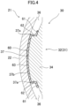
FIG. 4 is an enlarged view of a resin member of the electric motor and the periphery thereof inFIG. 3 . -
FIG. 5 is a horizontal cross-sectional view of a stator core during insert molding in the method for manufacturing the compressor according to the embodiment. -
FIG. 6 is an enlarged view of a resin member of the stator core and the periphery thereof inFIG. 5 . -
FIG. 7 is a horizontal cross-sectional view of a barrel during heating. -
FIG. 8 is a horizontal cross-sectional view of a stator core during joining. -
FIG. 9 shows a process of joining a first joining surface and a second joining surface by a method for manufacturing the compressor according to the embodiment. -
FIG. 10 is a vertical cross-sectional view of a resin member of a stator core and the periphery thereof during insert molding in the method for manufacturing a compressor according to a first variation. -
FIG. 11 shows a process of joining the first joining surface and the second joining surface in the method for manufacturing a compressor according to a second variation. -
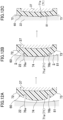
FIG. 12 shows a process of joining the first joining surface and the second joining surface in the method for manufacturing a compressor according to a third variation. -
FIG. 13 shows a process of joining the first joining surface and the second joining surface in the method for manufacturing a compressor according to a fourth variation. -
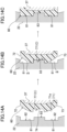
FIG. 14 shows a process of joining the first joining surface and the second joining surface in the method for manufacturing a compressor according to a fifth variation. -
FIG. 15 shows a process of joining the first joining surface and the second joining surface in the method for manufacturing a compressor according to a sixth variation. - Embodiments of the present disclosure will be described in detail below with reference to the drawings. The present disclosure is not limited to the embodiments shown below, and various changes can be made within the scope without departing from the technical concept of the present disclosure. Since each of the drawings is intended to illustrate the present disclosure conceptually, dimensions, ratios, or numbers may be exaggerated or simplified as necessary for the sake of ease of understanding.
- A compressor (20) of the present disclosure is provided for a refrigeration apparatus (1).
- The refrigeration apparatus (1) shown in
FIG. 1 includes the compressor (20) of the present disclosure. The refrigeration apparatus (1) has a refrigerant circuit (1a) filled with a refrigerant. The refrigerant circuit (1a) has a compressor (20), a radiator (2), a decompression mechanism (3), and an evaporator (4). The decompression mechanism (3) is an expansion valve. The refrigerant circuit (1a) performs a vapor compression refrigeration cycle. - In the refrigeration cycle, the refrigerant compressed by the compressor (20) dissipates heat to the air in the radiator (2). The refrigerant which has dissipated heat is decompressed by the decompression mechanism (3) and evaporates in the evaporator (4). The refrigerant which has evaporated is sucked into the compressor (20).
- The refrigeration apparatus (1) is an air conditioner. The air conditioner may be any of a cooling-only apparatus, a heating-only apparatus, or an air conditioner which switches between cooling and heating. In such a case, the air conditioner has a switching mechanism (e.g., a four-way switching valve) which switches a direction in which the refrigerant circulates. The refrigeration apparatus (1) may be a water heater, a chiller unit, or a cooling apparatus which cools the air in an internal space. The cooling apparatus cools the air in an internal space of a refrigerator, a freezer, a container, or the like. The expansion mechanism is an electronic expansion valve, a temperature-sensitive expansion valve, an expander, or a capillary tube.
- As illustrated in
FIG. 2 , the compressor (20) is a rotary fluid machinery. The compressor (20) has a casing (21), an electric motor (30), a drive shaft (28), and a compression mechanism (50). - The casing (21) houses the electric motor (30), the drive shaft (28), and the compression mechanism (50). The casing (21) is a hermetic container. The inside of the casing (21) is filled with a high-pressure refrigerant discharged from the compression mechanism (50).
- The casing (21) is made of a metal material. The casing (21) has a barrel (22), a bottom portion (23), and a top portion (24). The barrel (22) is a cylindrical metal member. At each of both ends of the barrel (22) in the axial direction, an opening is formed. In this example, the axial direction of the barrel (22) corresponds to the vertical direction. The bottom portion (23) closes the lower opening of the barrel (22). The top portion (24) closes the upper opening of the barrel (22).
- As illustrated in
FIGS. 2 and3 , the electric motor (30) is arranged above the compression mechanism (50). The electric motor (30) has a stator (31) and a rotor (40). The stator (31) is supported by the barrel (22) of the casing (21). The fixing structure for the stator (31) will be described in detail later. - The stator (31) has a stator core (32) and a coil (33) wound around the stator core (32). The stator core (32) includes electrical steel sheets stacked in the axial direction. As illustrated in
FIG. 3 , the stator core (32) has an annular back yoke (34) and a plurality of (six in this example) teeth (35) extending radially inward from the inner peripheral surface of the back yoke (34). - The outer peripheral surface of the back yoke (34) has a plurality of (six in this example) core cuts (36). The core cuts (36) are grooves extending in the axial direction of the stator core (32). A protrusion (37) protruding radially outward is provided between adjacent core cuts (36). The stator core (32) of the present example is provided with six protrusions (37). Each of the protrusions (37) has a pair of side surfaces (37a) extending radially outward and an end surface (37b) provided between the side surfaces (37a) in pair. The protrusion (37) extends toward both ends in the axial direction of the stator core (32).
- The rotor (40) is arranged inside the stator core (32). The drive shaft (28) is fixed in the axial center of the rotor (40). The rotor (40) is provided with a plurality of (four in this example) slots (41). A permanent magnet is embedded inside each of the slots (41).
- The operation frequency of the electric motor (30) is controlled by an inverter device. In other words, the compressor (20) is an inverter compressor having a variable operation frequency.
- The drive shaft (28) extends vertically along the axial center of the casing (21). The drive shaft (28) is rotated by the electric motor (30). The drive shaft (28) is rotatably supported by a bearing (29).
- The compression mechanism (50) has a cylinder (51) and a piston (52) provided inside the cylinder (51). A cylinder chamber (53) is formed between the inner peripheral surface of the cylinder (51) and the outer peripheral surface of the piston (52). In the cylinder chamber (53), a fluid is compressed by the piston (52) driven by the drive shaft (28).
- The compressor (20) has a suction pipe (45) and a discharge pipe (46). The suction pipe (45) penetrates the barrel (22) in the radial direction and communicates with the cylinder chamber (53). A low-pressure refrigerant in the refrigerant circuit (1a) is sucked into the cylinder chamber (53) through the suction pipe (45). The discharge pipe (46) penetrates the top portion (24) in the axial direction and communicates with an internal space of the casing (21). The refrigerant compressed in the compression mechanism (50) flows through portions, such as the core cuts (36) of the electric motor (30), and is then sent to the refrigerant circuit (1a) through the discharge pipe (46).
- Hereinafter, the fixing structure of the stator (31) will be described in detail. The compressor (20) of the present embodiment has resin members (60) provided on the outer peripheral surface of the stator core (32).
- As illustrated in
FIGS. 2 to 4 , the compressor (20) has resin members (60). The resin members (60) are located at the respective positions corresponding to the protrusions (37) of the stator core (32). Thus, the number of resin members (60) is the same as the number of protrusions (37). For example, eight protrusions (37) may be provided for the outer peripheral surface of the stator core (32). In such a case, the compressor (20) has eight resin members (60) corresponding to the respective protrusions (37). - Each of the resin members (60) is made of an insulating material. The resin member (60) has a function of reducing propagation of electromagnetic noise of the electric motor (30) to the outside of the casing (21). The resin member (60) is made of, for example, polyphenylene sulfide (PPS). The resin member (60) may be a liquid crystal polymer (LCP). The resin member (60) may be a composite material in which PPS contains glass fibers.
- The resin member (60) is fixed to the outer peripheral surface of the stator core (32). The resin member (60) extends toward both ends of the stator core (32) in the axial direction.
- The resin member (60) covers the entire surface of the protrusion (37) of the stator core (32). The resin member (60) is made of a pair of bases (61), a pair of sidewalls (62), and a fixing portion (63) that are combined together.
- The bases (61) in pair are provided on both sides of the base of the protrusion (37) on the outer peripheral surface of the back yoke (34). The bases (61) in pair extend along the outer peripheral surface of the back yoke (34).
- Each of the sidewalls (62) in pair covers an associated side surface (37a) of the protrusion (37). The sidewalls (62) in pair extend in the direction in which the protrusion (37) protrudes.
- The fixing portion (63) is continuous with radially outer ends of the sidewalls (62) in pair. The fixing portion (63) is arc-shaped along the inner peripheral surface of the barrel (22) in a cross section perpendicular to the axial direction of the barrel (22). The fixing portion (63) is located between the barrel (22) and the stator core (32).
- As will be described in detail later, the resin member (60) is formed on the outer peripheral surface of the stator core (32) by insert molding.
- The method for manufacturing the compressor (20) will be described in detail below with reference to
FIGS. 5 to 7 . The method for manufacturing a compressor (20) includes shrink fitting of fixing the stator core (32) to the inside of the barrel (22) via the resin members (60) by shrink fit. The shrink fitting includes: insert molding, heating, and joining. - In the insert molding shown in
FIG. 5 , the resin members (60) are formed on the outer peripheral surface of the stator core (32) by insert molding to obtain a unit (U). The insert molding allows the resin members (60) to be easily formed on the outer peripheral surface of the stator core (32). - The shape of the outer peripheral surface of the fixing portion (63) of the resin member (60) formed on the outer peripheral surface of the stator core (32) will be described in detail below with reference to
FIG. 6 . The outer peripheral surface of the fixing portion (63) is a first joining surface (71) of the present disclosure. The first joining surface (71) has a first end (72) and a second end (73) facing each other. The first end (72) and the second end (73) face each other in the circumferential direction of the stator core (32). The first end (72) and the second end (73) are portions at which the fixing portion (63) is connected to the sidewalls (62).FIG. 6 shows a portion of the barrel (22) for description of the first joining surface (71). - In the insert molding, the first joining surface (71) is arc-shaped when viewed from above the stator core (32). In other words, the first joining surface (71) is arc-shaped in the circumferential direction of the stator core (32). Specifically, the first joining surface (71) has a first curved surface (71a) having a first curvature 1/r1. In this example, the first curved surface (71a) is formed on the entire first joining surface (71). The first curved surface (71a) may be formed on a part of the first joining surface (71). The r1 is a curvature radius of the first curved surface (71a) centered around O1. The r1 is smaller than the radius of the stator core (32).
- When the stator core (32) is viewed from above, a portion of the first joining surface (71) located at a center between the first end (72) and the second end (73) is an intermediate portion (74). The intermediate portion (74) is located at the outermost position of the first joining surface (71) in the radial direction of the stator core (32). In the circumferential direction of the first joining surface (71), the distance between the intermediate portion (74) and the first end (72) is substantially equal to the distance between the intermediate portion (74) and the second end (73). The first curved surface (71a) is formed in the intermediate portion (74) of the first joining surface (71) when formed in a part of the first joining surface (71).
- As illustrated in
FIG. 6 , a portion of the inner peripheral surface of the barrel (22) in contact with the first joining surface (71) in the joining is a second joining surface (81). The second joining surface (81) has a second curvature 1/r2. The r2 is a curvature radius of the second joining surface (81) centered around O2. O2 coincides with the axial center of the barrel (22). Thus, the r2 is equal to the radius of the barrel (22). The first curvature 1/r1 is larger than the second curvature 1/rz of the second joining surface (81). - In the heating shown in
FIG. 7 , a tubular barrel (22) in the state in which the top portion (24) and the bottom portion (23) of the casing (21) are not fixed is used. In the heating, the barrel (22) of the casing (21) is heated. This causes thermal expansion of the barrel (22), and the diameters (the inner diameter and the outer diameter) of the barrel (22) increase. - The joining is a first step of the present disclosure. In the joining shown in
FIG. 8 , an operator inserts the unit (U) into the barrel (22). The heating makes the diameter of the barrel (22) increase, so that the unit (U) is easily inserted into the barrel (22). In the joining, the inner diameter of the barrel (22) is reduced, so that the unit (U) is fitted into the barrel (22). In other words, the unit (U) is fixed to the inside of the barrel (22) by shrink fit. - The process of joining the first joining surface (71) to the second joining surface (81) will be described below with reference to
FIG. 9 . In the process of reducing the inner diameter of the barrel (22), first, the intermediate portion (74) of the first joining surface (71) of the resin member (60) comes into contact with the second joining surface (81) (FIG. 9A ). At this time, spaces (S) are formed between the first joining surface (71) and the second joining surface (81) when the unit (U) and the barrel (22) are viewed from above. Specifically, the spaces (S) are formed between the first end (72) and the intermediate portion (74) and between the second end (73) and the intermediate portion (74). - The resin member (60) is first melted in the intermediate portion (74), and then gradually melted from the intermediate portion (74) toward the first end (72) and the second end (73) in the circumferential direction (
FIG. 9B ). Thereafter, the inner diameter of the barrel (22) decreases, so that the resin member (60) is gradually melted toward the first end (72) and the second end (73). Thus, the spaces (S) are gradually filled with the melted resin member (60). In this way, the joining area between the first joining surface (71) and the second joining surface (81) gradually increases, and eventually, the entire surface of the first joining surface (71) is joined to the second joining surface (81). If the first curvature is equal to the second curvature, the entire surface of the first joining surface (71) comes into contact with the second joining surface (81) all at once during the process of reducing the inner diameter of the barrel (22). Then, the resin member (60) on the entire surface of the first joining surface (71) melts, and the resin member (60) melted in the vicinities of the first end (72) and the second end (73) protrude from the first joining surface (71) and the second joining surface (81), thereby forming burrs. However, in this example, the melted resin member (60) flows toward the first end (72) and the second end (73) so as to gradually fill the spaces (S) therewith, thereby reducing protrusion of the resin member (60) from the first joining surface (71) and the second joining surface (81) (FIG. 9C ). As a result, generation of burrs of the resin member (60) can be securely reduced. - In the joining of the method for manufacturing the compressor (20) of the present embodiment, spaces (S) are formed between the first joining surface (71) and the second joining surface (81) upon contact of the intermediate portion (74) of the first joining surface (71) of the resin member (60) with the second joining surface (81) on the inner peripheral surface of the barrel (22). The spaces (S) are formed between the first end (72) and the intermediate portion (74) in the first joining surface (71) and between the second end (73) and the intermediate portion (74) in the first joining surface (71).
- The spaces (S) are formed on both sides of the intermediate portion (74), and thus, the spaces (S) are gradually filled with the melted resin member (60) from the intermediate portion (74) toward the first end (72) and the second end (73). This reduces protrusion of the resin member (60) from the first end (72) and the second end (73) as mentioned above, compared to the case in which the entire surface of the first joining surface (71) comes into contact with the second joining surface (81) all at once. As a result, generation of burrs of the protruded resin member (60) can be reduced, and failures in the compressor (20) and the refrigeration apparatus (1) including the compressor (20) can be reduced.
- In the method for manufacturing the compressor (20) of the present embodiment, the first end (72) and the second end (73) in the first joining surface (71) face each other in the circumferential direction of the stator core (32). This reduces protrusion of the resin member (60) in the circumferential direction of the first joining surface (71) and the second joining surface (81).
- In the method for manufacturing the compressor (20) according to the embodiment, the first joining surface (71) has a first curved surface (71a) having a first curvature. The first curvature is larger than a second curvature of the second joining surface (81). This allows the intermediate portion (74) of the first curved surface (71a) to first come into contact with the second joining surface (81), thereby forming spaces (S).
- The above embodiment may be implemented as the following variations. In the following description, differences from the embodiment will be described in principle.
- As illustrated in
FIG. 10 , the resin member (60) insert-molded in this variation is formed such that the vertical cross section of the first joining surface (71) is arc-shaped. In other words, the first joining surface (71) of this variation is arc-shaped in the axial direction of the barrel (22). The first end (72) and the second end (73) face each other in the axial direction of the stator core (32). Specifically, the first end (72) is located at the upper end of the first joining surface (71), and the second end (73) is located at the lower end of the first joining surface (71). In such a case, the intermediate portion (74) is located between the first end (72) and the second end (73). The intermediate portion (74) extends in the circumferential direction of the first joining surface (71). - When the intermediate portion (74) comes into contact with the second joining surface (81) in the joining, spaces (S) are formed in the top-bottom direction with the intermediate portion (74) interposed therebetween. As the first joining surface (71) approaches the second joining surface (81), the melted resin member (60) fills the spaces (S) in the top-bottom direction. This allows reduction in protrusion of the melted resin member (60) from the first end (72) and the second end (73). Since the first end (72) and the second end (73) are located at the upper and lower ends of the first joining surface (71), protrusion of the resin member (60) from the upper and lower ends of the stator core (32) due to the first joining surface (71) of this variation is reduced. This can reduce generation of burrs at the upper and lower ends of the stator core (32).
- In this variation, the first end (72) and the second end (73) may be provided in the circumferential direction as well as in the top-bottom direction of the first joining surface (71). In such a case, the intermediate portion (74) is located at the center of the first joining surface (71). With such a configuration, when the intermediate portion (74) comes into contact with the second joining surface (81) during joining, spaces (S) are formed in the top-bottom direction and the circumferential direction with the intermediate portion (74) interposed therebetween. This reduces protrusion of the melted resin member (60) not only in the top-bottom direction but also in the circumferential direction of the first joining surface (71), thereby reducing generation of burrs from the top-bottom and circumferential directions of the first joining surface (71).
- As illustrated in
FIG. 11A , the first joining surface (71) of this variation has a first convex portion (75) protruding radially outward of the stator core (32). The first convex portion (75) is located at a center portion of the first joining surface (71) in the circumferential direction and extends in the top-bottom direction of the first joining surface (71). The intermediate portion (74) is located at the distal end of the first convex portion (75). The first joining surface (71) of this variation has a first curvature 1/r1 larger than a second curvature 1/r2 as in the embodiment. - When the distal end (the intermediate portion (74)) of the first convex portion (75) comes into contact with the second joining surface (81) during the joining, a space (S) is formed on each side of the first convex portion (75) in the circumferential direction (
FIG. 11B ). In this way, also in this variation, the melted resin member (60) fills the spaces (S) toward the first end (72) and the second end (73) as the first joining surface (71) approaches the second joining surface (81) (FIG. 11B ). This reduces protrusion of the melted resin member (60) from the first end (72) and the second end (73), thereby reducing generation of burrs (FIG. 11C ). - As illustrated in
FIG. 12A , the first joining surface (71) of this variation has a first recess (76a) and a second recess (76b). The first recess (76a) is formed between the first end (72) and the intermediate portion (74). The second recess (76b) is formed between the second end (73) and the intermediate portion (74). The first recess (76a) and the second recess (76b) extend in the top-bottom direction of the first joining surface (71). The first joining surface (71) of this variation has a first curvature 1/r1 larger than a second curvature 1/r2 as in the embodiment. - When the intermediate portion (74) comes into contact with the second joining surface (81) in the joining, a space (S) is formed on each side of the intermediate portion (74) in the circumferential direction. The melted resin member (60) fills the spaces (S) toward the first end (72) and the second end (73) as the inner diameter of the barrel (22) decreases. In this process, the melted resin member (60) flows into the first recess (76a) and the second recess (76b) (
FIG. 12B ). This reliably reduces protrusion of the melted resin member (60) from the first end (72) and the second end (73). This reduces generation of burrs of the resin member (60) (FIG. 12C ). - As illustrated in
FIG. 13A , the inner peripheral surface of the barrel (22) of this variation has a groove (82) recessed radially outward. The second joining surface (81) of this variation is a bottom surface of the groove (82). The groove (82) extends in the axial direction (the top-bottom direction) of the barrel (22). The first joining surface (71) has a first curvature 1/r1 larger than a second curvature 1/r2 as in the embodiment. - Upon contact of the intermediate portion (74) with the second joining surface (81) in the joining, a space (S) is formed on each side of the intermediate portion (74) in the circumferential direction (
FIG. 13B ). The melted resin member (60) fills the spaces (S) toward the first end (72) and the second end (73) as the inner diameter of the barrel (22) decreases. Thereafter, the first end (72) and the second end (73) come into contact with the second joining surface (81) inside the groove (82), thereby reducing protrusion of the melted resin member (60) from the groove (82) (FIG. 13C ). This reduces generation of burrs of the resin member (60). - As illustrated in
FIG. 14A , the inner peripheral surface of the barrel (22) of this variation has grooves (82) recessed radially outward as in Fourth Variation. A second protrusion (83) protruding radially inward of the barrel (22) is formed in the grooves (82). The second joining surface (81) of this variation includes the bottom surfaces of the grooves (82) and the second protrusion (83). - The first joining surface (71) of this variation has a plane structure (C). The plane structure (C) is formed during insert molding. Due to the plane structure (C), spaces (S) are formed in the grooves (82) upon contact of the intermediate portion (74) with the second protrusion (83) in the joining. The plane structure (C) of this variation includes a third recess (77). The third recess (77) is formed such that the second protrusion (83) is fitted into the third recess (77) during joining. The third recess (77) extends in the top-bottom direction. The third recess (77) is located between the first end (72) and the second end (73). The intermediate portion (74) is located inside the third recess (77). The first joining surface (71) of this variation has a curved surface having a first curvature similar to that in the embodiment and the third recess (77). The curved surface having the first curvature and the third recess (77) are formed during the insert molding.
- During the joining, the second protrusion (83) of the second joining surface (81) is fitted into the third recess (77) of the first joining surface (71) (
FIG. 14B ). The intermediate portion (74) of this variation is the inner surface of the third recess (77). This allows formation of spaces (S) inside the grooves (82). The melted resin member (60) fills the spaces (S) toward the first end (72) and the second end (73) as the inner diameter of the barrel (22) decreases. The spaces (S) are formed inside the grooves (82). This reduces protrusion of the melted resin member (60) from the grooves (82). In addition, the second protrusion (83) is fitted into the third recess (77). This substantially prevents the first joining surface (71) from being displaced from the second joining surface (81) during the joining. Further, the second joining surface (81) has the grooves (82) and the second protrusion (83). This increases the fixing force to the resin member (60) as compared with the case in which the second joining surface (81) is flat. This substantially prevents the stator core (32) from being displaced inside the barrel (22) even when the rotor (40) is driven. - As illustrated in
FIG. 15A , the plane structure (C) of this variation is a third curved surface (71c) having a third curvature 1/r3 as viewed from above the stator core (32). The center of curvature of the third curvature 1/r3 is located outside the stator core (32). The third curved surface (71c) of this variation is formed on the entire first joining surface (71). Thus, r3 is a curvature radius of the first joining surface (71) of this variation. The third curved surface (71c) may be formed in a part of the first joining surface (71). In the joining, the first joining surface (71) is set to come into contact with the second protrusion (83), and the first end (72) and the second end (73) are set to come into contact with the second joining surface (81). - Upon contact of the first joining surface (71) with the second protrusion (83) in the joining, the first end (72) and the second end (73) come into contact with the second joining surface (81) (
FIG. 15B ). Specifically, the first joining surface (71) comes into contact with both ends of the top portion of the second protrusion (83). Portions of the first joining surface (71) in contact with both ends of the top portion are intermediate portions (74). Spaces (S) are formed between the intermediate portion (74) and the first end (72) and between the intermediate portion (74) and the second end (73). - The spaces (S) are filled with the resin member (60) as the inner diameter of the barrel (22) decreases. Since the spaces (S) are formed inside the grooves (82), and the first end (72) and the second end (73) are in contact with the bottom surfaces of the grooves (82) (the second joining surface (81)), protrusion of the melted resin member (60) from the grooves (82) is reduced (
FIG. 15C ). - The embodiment and variations may also be configured as follows.
The intermediate portion (74) only needs to be located between the first end (72) and the second end (73), and needs not to be centered between the first end (72) and the second end (73). - In Second Variation, during the joining, spaces (S) only need to be formed when the intermediate portion (74) of the first joining surface (71) comes into contact with the second joining surface (81), and the first curved surface (71a) needs not to be formed. For example, the first joining surface (71) may have a radius which is equal to the first curvature radius r2.
- In Fourth Variation, the bottom surface of the groove (82) (the second joining surface (81)) needs not to be flat. The second curvature of the second joining surface (81) only needs to be smaller than the first curvature.
- While the embodiment and variations thereof have been described above, it will be understood that various changes in form and details may be made without departing from the spirit and scope of the claims. The embodiment, the variation thereof, and the other embodiments may be combined and replaced with each other without deteriorating intended functions of the present disclosure.
- The ordinal numbers such as "first," "second," "third," ..., described above are used to distinguish the terms to which these expressions are given, and do not limit the number and order of the terms.
- As can be seen from the foregoing description, the present disclosure is useful for a method for manufacturing a compressor.
-
- S
- Space
- C
- Plane Structure
- 20
- Compressor
- 22
- Barrel
- 32
- Stator Core
- 60
- Resin Member
- 71
- First Joining Surface
- 71a
- First Curved Surface
- 71c
- Third Curved Surface
- 72
- First End
- 73
- Second End
- 74
- Intermediate Portion
- 75
- First Convex Portion
- 76a
- First Recess
- 76b
- Second Recess
- 81
- Second Joining Surface
- 82
- Groove
- 83
- Second Protrusion
Claims (10)
- A method for manufacturing a compressor (20) includinga tubular barrel (22),a stator core (32), anda resin member (60) provided on an outer peripheral surface of the stator core (32), the method comprising:fixing the stator core (32) to an inside of the barrel (22) via the resin member (60) by shrink fit, whereinwhen an outer peripheral surface of the resin member (60) is a first joining surface (71) and a surface in contact with the first joining surface (71) on an inner peripheral surface of the barrel (22) is a second joining surface (81), the fixing includes:a first step of joining the first joining surface (71) to the second joining surface (81), and in the first step,upon joining, to the second joining surface (81), an intermediate portion (74) of the first joining surface (71) between a first end (72) and a second end (73) facing each other, spaces (S) between the first joining surface (71) and the second joining surface (81) are formed between the first end (72) and the intermediate portion (74) and between the second end (73) and the intermediate portion (74).
- The method of claim 1, wherein
the first end (72) and the second end (73) face each other in a circumferential direction of the stator core (32). - The method of claim 1 or 2, wherein
the first end (72) and the second end (73) face each other in an axial direction of the stator core (32). - The method of any one of claims 1 to 3, whereinthe first joining surface (71) has a first curved surface (71a) having a first curvature,the intermediate portion (74) is located in the first curved surface (71a), andthe first curvature is larger than a second curvature of the second joining surface (81).
- The method of any one of claims 1 to 4, whereinthe first joining surface (71) has a first convex portion (75) protruding radially outward of the stator core (32), andthe intermediate portion (74) is located in the first convex portion (75).
- The method of any one of claims 1 to 5, whereinthe first joining surface (71) hasa first recess (76a) formed between the first end (72) and the intermediate portion (74), anda second recess (76b) formed between the second end (73) and the intermediate portion (74).
- The method of any one of claims 1 to 6, whereinthe inner peripheral surface of the barrel (22) has a groove (82) recessed radially outward, andthe second joining surface (81) is a bottom surface of the groove (82).
- The method of claim 7, whereinthe second joining surface (81) has a second protrusion (83) protruding radially inward of the barrel (22), andthe first joining surface (71) hasa plane structure (C) by which the spaces (S) are formed inside the groove (82) upon contact of the intermediate portion (74) with the second protrusion (83) in the first step.
- The method of claim 8, wherein
the plane structure (C) has a third recess into which the second protrusion (83) is fitted in the first step. - The method of claim 8, wherein
the plane structure (C) includes a third curved surface (71c) having a third curvature centered around a point outside the stator core (32).
Applications Claiming Priority (2)
| Application Number | Priority Date | Filing Date | Title |
|---|---|---|---|
| JP2021132637A JP7148828B1 (en) | 2021-08-17 | 2021-08-17 | Compressor manufacturing method |
| PCT/JP2022/022357 WO2023021811A1 (en) | 2021-08-17 | 2022-06-01 | Method for manufacturing compressor |
Publications (2)
| Publication Number | Publication Date |
|---|---|
| EP4361439A1 true EP4361439A1 (en) | 2024-05-01 |
| EP4361439A4 EP4361439A4 (en) | 2024-11-06 |
Family
ID=83507678
Family Applications (1)
| Application Number | Title | Priority Date | Filing Date |
|---|---|---|---|
| EP22858135.1A Pending EP4361439A4 (en) | 2021-08-17 | 2022-06-01 | METHOD FOR MANUFACTURING A COMPRESSOR |
Country Status (5)
| Country | Link |
|---|---|
| US (1) | US12463513B2 (en) |
| EP (1) | EP4361439A4 (en) |
| JP (1) | JP7148828B1 (en) |
| CN (1) | CN117795198A (en) |
| WO (1) | WO2023021811A1 (en) |
Family Cites Families (6)
| Publication number | Priority date | Publication date | Assignee | Title |
|---|---|---|---|---|
| JPH0283393U (en) * | 1988-12-16 | 1990-06-27 | ||
| JP4592143B2 (en) | 2000-04-06 | 2010-12-01 | パナソニック株式会社 | Compressor and electric motor |
| JP2009079529A (en) * | 2007-09-26 | 2009-04-16 | Sanden Corp | Scroll fluid machine |
| JP2018201308A (en) * | 2017-05-29 | 2018-12-20 | 川本電産株式会社 | Motor and method for manufacturing motor |
| EP4002648A4 (en) * | 2019-09-30 | 2023-08-16 | Daikin Industries, Ltd. | ROTATING ELECTRIC MACHINE, COMPRESSOR AND METHOD FOR MAKING ROTATING ELECTRIC MACHINE |
| JP7168883B2 (en) * | 2021-03-26 | 2022-11-10 | ダイキン工業株式会社 | Rotating Machinery Units, Compressors, and Refrigeration Equipment |
-
2021
- 2021-08-17 JP JP2021132637A patent/JP7148828B1/en active Active
-
2022
- 2022-06-01 CN CN202280053753.1A patent/CN117795198A/en active Pending
- 2022-06-01 WO PCT/JP2022/022357 patent/WO2023021811A1/en not_active Ceased
- 2022-06-01 EP EP22858135.1A patent/EP4361439A4/en active Pending
-
2024
- 2024-02-13 US US18/440,192 patent/US12463513B2/en active Active
Also Published As
| Publication number | Publication date |
|---|---|
| US20240186870A1 (en) | 2024-06-06 |
| JP2023027506A (en) | 2023-03-02 |
| US12463513B2 (en) | 2025-11-04 |
| CN117795198A (en) | 2024-03-29 |
| WO2023021811A1 (en) | 2023-02-23 |
| JP7148828B1 (en) | 2022-10-06 |
| EP4361439A4 (en) | 2024-11-06 |
Similar Documents
| Publication | Publication Date | Title |
|---|---|---|
| US8513851B2 (en) | Insulator for motor, stator, motor and compressor | |
| CN109690914B (en) | Stator, motor and compressor | |
| CN102638118B (en) | Rotor, sealed compressor, and refrigerating cycle device | |
| KR101892405B1 (en) | Compressor and method for manufacturing compressor | |
| CN105545746B (en) | Compressor Manufacturing device and Compressor Manufacturing method | |
| US20240014698A1 (en) | Rotary machine unit, compressor, and refrigeration device | |
| JP6406373B2 (en) | Compressor motor, compressor, refrigeration cycle apparatus, and compressor motor manufacturing method | |
| KR102320908B1 (en) | Compressors and refrigeration cycle units | |
| US12463513B2 (en) | Method for manufacturing compressor | |
| EP4407837B1 (en) | Rotating electric machine, compressor, and refrigerator device | |
| JPWO2017064782A1 (en) | Stator core, compressor and refrigeration cycle device | |
| JP7511759B2 (en) | Compressor motor, compressor, refrigeration cycle device, and method for manufacturing compressor motor | |
| JP4156506B2 (en) | Electric motor, hermetic compressor, refrigeration air conditioner and wedge | |
| EP4401287A1 (en) | Compressor, refrigeration device, and method for manufacturing compressor | |
| JP5135779B2 (en) | Compressor | |
| EP4462645B1 (en) | Electric motor | |
| CN205105013U (en) | compressor | |
| US20250226708A1 (en) | Rotating electric machine, compressor, and refrigeration device | |
| JP6590904B2 (en) | Compressor manufacturing apparatus and compressor manufacturing method | |
| JP2008138591A5 (en) | ||
| JP2026001142A5 (en) |
Legal Events
| Date | Code | Title | Description |
|---|---|---|---|
| STAA | Information on the status of an ep patent application or granted ep patent |
Free format text: STATUS: THE INTERNATIONAL PUBLICATION HAS BEEN MADE |
|
| PUAI | Public reference made under article 153(3) epc to a published international application that has entered the european phase |
Free format text: ORIGINAL CODE: 0009012 |
|
| STAA | Information on the status of an ep patent application or granted ep patent |
Free format text: STATUS: REQUEST FOR EXAMINATION WAS MADE |
|
| 17P | Request for examination filed |
Effective date: 20240126 |
|
| AK | Designated contracting states |
Kind code of ref document: A1 Designated state(s): AL AT BE BG CH CY CZ DE DK EE ES FI FR GB GR HR HU IE IS IT LI LT LU LV MC MK MT NL NO PL PT RO RS SE SI SK SM TR |
|
| P01 | Opt-out of the competence of the unified patent court (upc) registered |
Free format text: CASE NUMBER: APP_38500/2024 Effective date: 20240627 |
|
| REG | Reference to a national code |
Ref country code: DE Ref legal event code: R079 Free format text: PREVIOUS MAIN CLASS: F04B0039000000 Ipc: F04B0035040000 |
|
| A4 | Supplementary search report drawn up and despatched |
Effective date: 20241007 |
|
| RIC1 | Information provided on ipc code assigned before grant |
Ipc: F04C 23/00 20060101ALN20240930BHEP Ipc: F04C 18/356 20060101ALN20240930BHEP Ipc: H02K 15/12 20060101ALI20240930BHEP Ipc: H02K 1/18 20060101ALI20240930BHEP Ipc: F04B 39/14 20060101ALI20240930BHEP Ipc: F04B 39/12 20060101ALI20240930BHEP Ipc: F04B 35/04 20060101AFI20240930BHEP |
|
| DAV | Request for validation of the european patent (deleted) | ||
| DAX | Request for extension of the european patent (deleted) | ||
| STAA | Information on the status of an ep patent application or granted ep patent |
Free format text: STATUS: EXAMINATION IS IN PROGRESS |
|
| 17Q | First examination report despatched |
Effective date: 20250620 |