EP4361438A1 - Heat pump compressor - Google Patents
Heat pump compressor Download PDFInfo
- Publication number
- EP4361438A1 EP4361438A1 EP23204371.1A EP23204371A EP4361438A1 EP 4361438 A1 EP4361438 A1 EP 4361438A1 EP 23204371 A EP23204371 A EP 23204371A EP 4361438 A1 EP4361438 A1 EP 4361438A1
- Authority
- EP
- European Patent Office
- Prior art keywords
- compressor
- bldc motor
- rotor
- pressure chamber
- stator
- Prior art date
- Legal status (The legal status is an assumption and is not a legal conclusion. Google has not performed a legal analysis and makes no representation as to the accuracy of the status listed.)
- Granted
Links
Images


Classifications
-
- F—MECHANICAL ENGINEERING; LIGHTING; HEATING; WEAPONS; BLASTING
- F04—POSITIVE - DISPLACEMENT MACHINES FOR LIQUIDS; PUMPS FOR LIQUIDS OR ELASTIC FLUIDS
- F04B—POSITIVE-DISPLACEMENT MACHINES FOR LIQUIDS; PUMPS
- F04B35/00—Piston pumps specially adapted for elastic fluids and characterised by the driving means to their working members, or by combination with, or adaptation to, specific driving engines or motors, not otherwise provided for
- F04B35/04—Piston pumps specially adapted for elastic fluids and characterised by the driving means to their working members, or by combination with, or adaptation to, specific driving engines or motors, not otherwise provided for the means being electric
-
- F—MECHANICAL ENGINEERING; LIGHTING; HEATING; WEAPONS; BLASTING
- F04—POSITIVE - DISPLACEMENT MACHINES FOR LIQUIDS; PUMPS FOR LIQUIDS OR ELASTIC FLUIDS
- F04B—POSITIVE-DISPLACEMENT MACHINES FOR LIQUIDS; PUMPS
- F04B39/00—Component parts, details, or accessories, of pumps or pumping systems specially adapted for elastic fluids, not otherwise provided for in, or of interest apart from, groups F04B25/00 - F04B37/00
- F04B39/06—Cooling; Heating; Prevention of freezing
-
- F—MECHANICAL ENGINEERING; LIGHTING; HEATING; WEAPONS; BLASTING
- F04—POSITIVE - DISPLACEMENT MACHINES FOR LIQUIDS; PUMPS FOR LIQUIDS OR ELASTIC FLUIDS
- F04B—POSITIVE-DISPLACEMENT MACHINES FOR LIQUIDS; PUMPS
- F04B39/00—Component parts, details, or accessories, of pumps or pumping systems specially adapted for elastic fluids, not otherwise provided for in, or of interest apart from, groups F04B25/00 - F04B37/00
- F04B39/06—Cooling; Heating; Prevention of freezing
- F04B39/066—Cooling by ventilation
-
- F—MECHANICAL ENGINEERING; LIGHTING; HEATING; WEAPONS; BLASTING
- F04—POSITIVE - DISPLACEMENT MACHINES FOR LIQUIDS; PUMPS FOR LIQUIDS OR ELASTIC FLUIDS
- F04B—POSITIVE-DISPLACEMENT MACHINES FOR LIQUIDS; PUMPS
- F04B39/00—Component parts, details, or accessories, of pumps or pumping systems specially adapted for elastic fluids, not otherwise provided for in, or of interest apart from, groups F04B25/00 - F04B37/00
- F04B39/12—Casings; Cylinders; Cylinder heads; Fluid connections
- F04B39/123—Fluid connections
Definitions
- the invention refers to the design of a compressor for the refrigerant circuit of a heat pump device intended mainly for heating and/or cooling of buildings.
- Heat pump heating systems extract heat from the ambient medium (air, water, soil) and make it available for use, for example by transferring it to drinking water for the preparation of domestic hot water or also by transferring it to the heating circuit for the purpose of heating the living space.
- the basis of a heat pump is a closed circuit filled with refrigerant.
- the heat pump, or its cooling circuit has essentially four basic parts - an evaporator, a compressor, a condenser and an expansion valve.
- the refrigerant in the cooling circuit often undergoes a phase change, transfers heat, releases heat by condensation and absorbs heat by evaporation.
- the heat pump circuits use a compressor.
- the compressor which drives the movement of all fluids in the heat pump cooling circuit, is the most important and mechanically most stressed part of the cooling circuit.
- Compressors to drive gas compression work on the principle of piston, eccentric or screw design, while in heat pumps the eccentric principle is most often used.
- the compressor assembly consists of two parts, a compressor and an electric motor, which is used to rotate the corresponding eccentric cam to compress gas.
- the electric motor used is either alternating current (AC) single-phase or three-phase with a squirrel cage. More modern compressors having an electronically commutated direct current (DC) electric motor are also known in the state of the art.
- the rotor of the electric motor is made by a cylindrical permanent magnet, for example made of high temperature resistant Al-Ni-Co alloy.
- the electric motor of the compressor is heated by refrigerant. This is due to the fact that the compressed gas outlet from the compressor part is routed into the rotor and stator area, thereby heating both the stator and the rotor of the compressor electric motor. This places unreasonable thermal load on the permanent magnet of the rotor and also on the stator coil.
- the winding of the stator coil may be damaged (short circuit between windings, etc.)
- Compressors with a traditional electric motor have a rather complicated operation control (a frequency converter is needed), the aim is to regulate the heat pump so that the number of shutdowns does not exceed the number set by the designers.
- the heat pump also has a protection of the electric motor against extremely short off and on cycles (e.g. at least 3 minutes after switching off until the compressor is switched on again).
- the invention discloses an improved compressor using a commutatorless brushless (BL) direct-current (DC) electric motor (hereinafter BLDC motor).
- BLDC motor commutatorless brushless (BL) direct-current (DC) electric motor
- a rotor made as a permanent magnet rotates; the rotation is achieved by changing the direction of the magnetic fields generated by the surrounding stationary electromagnetic coils. To control the rotation it is necessary to control the magnitude and direction of the current conducted into the electromagnetic coils.
- the rotor Since the rotor is a permanent magnet, it does not need current, eliminating the need for brushes and a commutator.
- the current to the fixed electromagnetic coils is controlled externally.
- BLDC motors can drive continuously at maximum rotational force (torque). Even small BLDC motors can deliver considerable power.
- BLDC motors can be controlled using feedback mechanisms to achieve the exact torque and rotational speed required.
- the BLDC motor of the compressor can be controlled by PWM signals, no frequency converter is required.
- BLDC motors are also characterised by high durability and low electrical noise production due to the absence of brushes. Therefore, BLDC motors are often considered preferable to brush motors in applications where it is important to avoid electrical noise.
- the improvement of the compressor design according to the presented invention consists in the fact that the electromagnetic coils of the BLDC motor stator will be separated from the pressure part of the compressor by a housing and atmosphere (it will not be part of the internal pressure part of the compressor).
- the refrigerant inlet will be routed to the BLDC motor rotor of the compressor and the BLDC motor rotor of the compressor will be cooled (not heated) by the refrigerant.
- the shape of the rotor of the electric motor of the compressor is also changed from cylindrical to helical to provide additional flow of refrigerant to the compression part and to overfill the compressor chamber.
- the rotor of the electric motor of the compressor can be made as a permanent magnet from a cheaper material designed for lower temperatures (e.g. neodymium, ferrite, etc.).
- a compressor for the refrigeration circuit of a heat pump device intended for a heating and/or cooling device having a refrigerant inlet connection 5, refrigerant outlet connections 8, 9 and a compressor block 7 controlled by a BLDC motor, wherein the BLDC motor comprises a rotor 2 and a stator 3 equipped with electromagnetic coils 4.
- the rotor 2 of the BLDC motor is made as a permanent magnet coupled to the shaft 1, with the shaft 1 arranged in the pressure chamber 6 of the compressor and housed in the plain bearings 11.
- the permanent magnet (rotor) 2 has a special helical shape to improve the refrigerant flow and to overfill the pressure chamber 6 of the compressor. Refrigerant flows into the pressure chamber 6 of the compressor through the refrigerant inlet connection 5 and heated refrigerant exits through the refrigerant outlet connections 8, 9.
- the stator 3 of the BLDC motor is equipped with six electromagnetic coils 4 and is arranged outside the pressure chamber 6 of the compressor.
- the stator 3 of the BLDC motor is arranged on the outside of the housing 10 of the compressor pressure chamber, so that the electromagnetic coils 4 of the stator are within the magnetic field of the permanent magnet of the rotor 2.
- the stator 3 of the BLDC motor can be mounted on the housing 10 by sliding, pressing, or in other suitable way.
- the refrigerant is routed in the compressor pressure chamber 6 through the helical body of the rotor 2 of the BLDC electric motor to provide cooling to the rotor 2.
- the shaft 1 and the refrigerant inlet connection 5 are connected to the compressor block 7, arranged in the compressor pressure chamber 6.
- the compressor block 7 is constructed as a two-piston eccentric, BLDC motor-driven mechanism, with two refrigerant outlet connections 8, 9.
- This compressor arrangement ensures that the compressed (heated and hot) refrigerant routed via outlet connections 8, 9 are no longer routed to the BLDC motor area and the BLDC motor is not exposed to heat, thus ensuring longer compressor life.
- the refrigerant outlet connections 8,9 of the compressor block 7 are routed outside the area of the BLDC motor stator 3 location.
- the scope of the patent protection includes also a heating device with a heat pump equipped with a compressor according to the disclosed invention.
Landscapes
- Engineering & Computer Science (AREA)
- Mechanical Engineering (AREA)
- General Engineering & Computer Science (AREA)
- Applications Or Details Of Rotary Compressors (AREA)
- Compressor (AREA)
Abstract
characterized in that the rotor (2) of the BLDC motor is made as a permanent magnet, with the permanent magnet in a helical shape,
the rotor (2) of the BLDC motor is arranged in a pressure chamber (6) of the compressor and is connected to a shaft (1),
the stator (3) of the BLDC motor is arranged outside the pressure chamber (6) of the compressor and is equipped with electromagnetic coils (4),
the refrigerant is routed into the pressure chamber (6) of the compressor through the helical body of the rotor (2) of the BLDC motor to provide cooling to the rotor (2) and to overfill the compressor pressure chamber (6).
Description
- The invention refers to the design of a compressor for the refrigerant circuit of a heat pump device intended mainly for heating and/or cooling of buildings.
- Heat pump heating systems extract heat from the ambient medium (air, water, soil) and make it available for use, for example by transferring it to drinking water for the preparation of domestic hot water or also by transferring it to the heating circuit for the purpose of heating the living space.
- The basis of a heat pump is a closed circuit filled with refrigerant. The heat pump, or its cooling circuit, has essentially four basic parts - an evaporator, a compressor, a condenser and an expansion valve.
- The refrigerant in the cooling circuit often undergoes a phase change, transfers heat, releases heat by condensation and absorbs heat by evaporation. In order to provide a pressure differential for the phase change in the condenser or evaporator, the heat pump circuits use a compressor.
- The compressor, which drives the movement of all fluids in the heat pump cooling circuit, is the most important and mechanically most stressed part of the cooling circuit.
- Compressors to drive gas compression work on the principle of piston, eccentric or screw design, while in heat pumps the eccentric principle is most often used.
- The compressor assembly consists of two parts, a compressor and an electric motor, which is used to rotate the corresponding eccentric cam to compress gas.
- The electric motor used is either alternating current (AC) single-phase or three-phase with a squirrel cage. More modern compressors having an electronically commutated direct current (DC) electric motor are also known in the state of the art. The rotor of the electric motor is made by a cylindrical permanent magnet, for example made of high temperature resistant Al-Ni-Co alloy.
- During normal operation of the heat pump compressor, the electric motor of the compressor is heated by refrigerant. This is due to the fact that the compressed gas outlet from the compressor part is routed into the rotor and stator area, thereby heating both the stator and the rotor of the compressor electric motor. This places unreasonable thermal load on the permanent magnet of the rotor and also on the stator coil.
- An example of such an arrangement is the heat pump compressor described in document
EP3006848 A1 . - Due to heat and vibration, the winding of the stator coil may be damaged (short circuit between windings, etc.)
- Compressors with a traditional electric motor have a rather complicated operation control (a frequency converter is needed), the aim is to regulate the heat pump so that the number of shutdowns does not exceed the number set by the designers.
- The heat pump also has a protection of the electric motor against extremely short off and on cycles (e.g. at least 3 minutes after switching off until the compressor is switched on again).
- However, to avoid overheating of the electric motor, the compressor should be switched off (and on) more often, which is undesirable. The requirements for compressor operation and the overheating protection of a traditional motor are therefore in conflict.
- These shortcomings are eliminated by the new design of a heat pump compressor according to the presented invention.
- The invention discloses an improved compressor using a commutatorless brushless (BL) direct-current (DC) electric motor (hereinafter BLDC motor).
- In a BLDC motor, a rotor made as a permanent magnet rotates; the rotation is achieved by changing the direction of the magnetic fields generated by the surrounding stationary electromagnetic coils. To control the rotation it is necessary to control the magnitude and direction of the current conducted into the electromagnetic coils.
- Since the rotor is a permanent magnet, it does not need current, eliminating the need for brushes and a commutator. The current to the fixed electromagnetic coils is controlled externally.
- One of the great advantages of a BLDC motor is efficiency, as these motors can drive continuously at maximum rotational force (torque). Even small BLDC motors can deliver considerable power.
- Another great advantage is the possibility of regulation. BLDC motors can be controlled using feedback mechanisms to achieve the exact torque and rotational speed required.
- The BLDC motor of the compressor can be controlled by PWM signals, no frequency converter is required.
- Precise control subsequently reduces energy consumption and heat production.
- BLDC motors are also characterised by high durability and low electrical noise production due to the absence of brushes. Therefore, BLDC motors are often considered preferable to brush motors in applications where it is important to avoid electrical noise.
- Ideal applications for BLDC motors are therefore in all equipment that operates continuously and thus also in heating and/or air conditioning equipment.
- The improvement of the compressor design according to the presented invention consists in the fact that the electromagnetic coils of the BLDC motor stator will be separated from the pressure part of the compressor by a housing and atmosphere (it will not be part of the internal pressure part of the compressor).
- The refrigerant inlet will be routed to the BLDC motor rotor of the compressor and the BLDC motor rotor of the compressor will be cooled (not heated) by the refrigerant.
- The shape of the rotor of the electric motor of the compressor is also changed from cylindrical to helical to provide additional flow of refrigerant to the compression part and to overfill the compressor chamber.
- Due to this arrangement, the rotor of the electric motor of the compressor can be made as a permanent magnet from a cheaper material designed for lower temperatures (e.g. neodymium, ferrite, etc.).
- The invention is further explained using the figures below, without limitation thereto.
- The figures show:
-
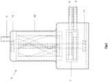
Fig. 1 - BLDC motor rotor of the compressor (helical shape) -
Fig. 2 - Compressor pressure chamber with refrigerant connection pipes and BLDC motor rotor mounted -
Fig. 3 - Compressor pressure chamber and BLDC motor stator with electromagnetic coils arranged on the outside of the pressure chamber - A compressor for the refrigeration circuit of a heat pump device intended for a heating and/or cooling device, having a
refrigerant inlet connection 5,refrigerant outlet connections compressor block 7 controlled by a BLDC motor, wherein the BLDC motor comprises arotor 2 and astator 3 equipped withelectromagnetic coils 4. - The
rotor 2 of the BLDC motor is made as a permanent magnet coupled to theshaft 1, with theshaft 1 arranged in thepressure chamber 6 of the compressor and housed in theplain bearings 11. - The permanent magnet (rotor) 2, has a special helical shape to improve the refrigerant flow and to overfill the
pressure chamber 6 of the compressor. Refrigerant flows into thepressure chamber 6 of the compressor through therefrigerant inlet connection 5 and heated refrigerant exits through therefrigerant outlet connections - The
stator 3 of the BLDC motor is equipped with sixelectromagnetic coils 4 and is arranged outside thepressure chamber 6 of the compressor. - In the example embodiment, the
stator 3 of the BLDC motor is arranged on the outside of thehousing 10 of the compressor pressure chamber, so that theelectromagnetic coils 4 of the stator are within the magnetic field of the permanent magnet of therotor 2. - The
stator 3 of the BLDC motor can be mounted on thehousing 10 by sliding, pressing, or in other suitable way. - The refrigerant is routed in the
compressor pressure chamber 6 through the helical body of therotor 2 of the BLDC electric motor to provide cooling to therotor 2. - The
shaft 1 and therefrigerant inlet connection 5 are connected to thecompressor block 7, arranged in thecompressor pressure chamber 6. In this example embodiment, thecompressor block 7 is constructed as a two-piston eccentric, BLDC motor-driven mechanism, with tworefrigerant outlet connections - This compressor arrangement ensures that the compressed (heated and hot) refrigerant routed via
outlet connections refrigerant outlet connections compressor block 7 are routed outside the area of the BLDCmotor stator 3 location. - Obviously, the above described example embodiment illustrates the basic principle of the invention. The figures are simplified and show the principle of the invention, neither the construction details nor electrical wires are drawn.
- Obviously, in other example embodiments, other types of bearings may be used and also different arrangements thereof, different compression machine mechanism, the number of electromagnetic stator coils may also be different, for example, in the range of 1 to 8.
- The scope of the patent protection includes also a heating device with a heat pump equipped with a compressor according to the disclosed invention.
-
- 1 shaft
- 2 rotor (permanent magnet)
- 3 stator
- 4 electromagnetic coil
- 5 refrigerant inlet connection
- 6 compressor pressure chamber
- 7 compressor block
- 8 refrigerant outlet connection
- 9 refrigerant outlet connection
- 10 pressure chamber housing
- 11 bearings
Claims (6)
- A compressor for a heat pump refrigerant circuit, comprising a refrigerant inlet connection (5), refrigerant outlet connections (8,9) and a compressor block (7) controlled by a BLDC motor with a rotor (2) and a stator (3),
characterized in thatthe rotor (2) of the BLDC motor is made as a permanent magnet, with the permanent magnet in a helical shape,the rotor (2) of the BLDC motor is arranged in a pressure chamber (6) of the compressor and is connected to a shaft (1),the stator (3) of the BLDC motor is arranged outside the pressure chamber (6) of the compressor and is equipped with electromagnetic coils (4),the refrigerant is routed into the pressure chamber (6) of the compressor through the helical body of the rotor (2) of the BLDC motor to provide cooling to the rotor (2) and to overfill the compressor pressure chamber (6). - The compressor according to claim 1,
characterized in that
the shaft (1) is housed in the bearings (11) and is connected to the compressor block (7). - The compressor according to claim 1 or 2,
characterized in that
the compressor block (7) is equipped with a two-piston eccentric mechanism controlled by a BLDC motor. - The compressor according to any one of the above claims,
characterized in that
the stator (3) of the BLDC motor is fixed to the housing (10) of the compressor pressure chamber (6) by sliding, pressing or other suitable means so that the electromagnetic coils (4) of the stator (3) of the BLDC motor are within the magnetic field of the rotor (2). - The compressor according to any one of the above claims,
characterized in that
the refrigerant outlet connections (8,9) of the compressor block (7) are routed outside the area of the BLDC motor stator (3) location. - A heating and/or cooling device with a heat pump,
characterized in that
the heat pump is equipped with a compressor according to any one of claims 1 to 5.
Applications Claiming Priority (1)
| Application Number | Priority Date | Filing Date | Title |
|---|---|---|---|
| SK135-2022U SK9861Y1 (en) | 2022-10-27 | 2022-10-27 | Heat pump compressor |
Publications (2)
| Publication Number | Publication Date |
|---|---|
| EP4361438A1 true EP4361438A1 (en) | 2024-05-01 |
| EP4361438B1 EP4361438B1 (en) | 2024-12-04 |
Family
ID=86325457
Family Applications (1)
| Application Number | Title | Priority Date | Filing Date |
|---|---|---|---|
| EP23204371.1A Active EP4361438B1 (en) | 2022-10-27 | 2023-10-18 | Heat pump compressor |
Country Status (2)
| Country | Link |
|---|---|
| EP (1) | EP4361438B1 (en) |
| SK (1) | SK9861Y1 (en) |
Citations (5)
| Publication number | Priority date | Publication date | Assignee | Title |
|---|---|---|---|---|
| FR2961271A1 (en) * | 2010-06-15 | 2011-12-16 | Valeo Thermal Sys Japan Co | ELECTRIC COMPRESSOR |
| US20130156617A1 (en) * | 2010-06-15 | 2013-06-20 | Valeo Japan Co., Ltd. | Short-Shaft Electric Compressor |
| EP3006848A1 (en) | 2013-05-24 | 2016-04-13 | Mitsubishi Electric Corporation | Heat pump device |
| US20180073521A1 (en) * | 2015-03-19 | 2018-03-15 | Mitsubishi Heavy Industries Thermal Systems, Ltd. | Compressor driving motor and cooling method for same |
| US10767639B2 (en) * | 2013-03-04 | 2020-09-08 | Wabco Gmbh | Compressor arrangement for compressed air supply facility |
-
2022
- 2022-10-27 SK SK135-2022U patent/SK9861Y1/en unknown
-
2023
- 2023-10-18 EP EP23204371.1A patent/EP4361438B1/en active Active
Patent Citations (5)
| Publication number | Priority date | Publication date | Assignee | Title |
|---|---|---|---|---|
| FR2961271A1 (en) * | 2010-06-15 | 2011-12-16 | Valeo Thermal Sys Japan Co | ELECTRIC COMPRESSOR |
| US20130156617A1 (en) * | 2010-06-15 | 2013-06-20 | Valeo Japan Co., Ltd. | Short-Shaft Electric Compressor |
| US10767639B2 (en) * | 2013-03-04 | 2020-09-08 | Wabco Gmbh | Compressor arrangement for compressed air supply facility |
| EP3006848A1 (en) | 2013-05-24 | 2016-04-13 | Mitsubishi Electric Corporation | Heat pump device |
| US20180073521A1 (en) * | 2015-03-19 | 2018-03-15 | Mitsubishi Heavy Industries Thermal Systems, Ltd. | Compressor driving motor and cooling method for same |
Also Published As
| Publication number | Publication date |
|---|---|
| SK9861Y1 (en) | 2023-09-27 |
| EP4361438B1 (en) | 2024-12-04 |
| SK1352022U1 (en) | 2023-05-17 |
Similar Documents
| Publication | Publication Date | Title |
|---|---|---|
| EP2146161B1 (en) | Capacity modulation compressor and air conditioning system having the same | |
| JP3629587B2 (en) | Air conditioner, outdoor unit and refrigeration system | |
| CN102483054B (en) | Motor cooling applications | |
| US20100011806A1 (en) | Motor, compressor and air conditioning system having the same | |
| US10027191B2 (en) | Compressor, heat pump device, air conditioner, and freezing machine | |
| KR101023351B1 (en) | Variable displacement compressors and air conditioning systems having the same | |
| US20130315758A1 (en) | Electro-hydraulic pump (e-pump) | |
| JP7407836B2 (en) | Heating, ventilation, air conditioning and/or refrigeration systems with compressor motor cooling systems | |
| WO2020170390A1 (en) | Motor, compressor, and air conditioning device | |
| CN101277037B (en) | Brushless direct current motor, compressor and air conditioner having the same | |
| WO2009084245A1 (en) | Electric motor for compressor, compressor, and freezing cycle device | |
| JPWO2020170418A1 (en) | Motors, compressors and air conditioners | |
| EP4361438B1 (en) | Heat pump compressor | |
| JP4595372B2 (en) | Compressor, compressor drive control device, and compressor drive control method | |
| JP3984864B2 (en) | Refrigeration equipment and compressor | |
| JP2016077093A (en) | Air conditioner | |
| JP3637368B2 (en) | Refrigeration equipment | |
| US20200011337A1 (en) | Impeller integrated motor for centrifugal compressor | |
| JP4203915B2 (en) | Refrigeration equipment | |
| KR20260046079A (en) | Axial flux motor for HVAC & R systems | |
| KR20110098704A (en) | Air conditioning system and its control method |
Legal Events
| Date | Code | Title | Description |
|---|---|---|---|
| PUAI | Public reference made under article 153(3) epc to a published international application that has entered the european phase |
Free format text: ORIGINAL CODE: 0009012 |
|
| STAA | Information on the status of an ep patent application or granted ep patent |
Free format text: STATUS: THE APPLICATION HAS BEEN PUBLISHED |
|
| STAA | Information on the status of an ep patent application or granted ep patent |
Free format text: STATUS: REQUEST FOR EXAMINATION WAS MADE |
|
| AK | Designated contracting states |
Kind code of ref document: A1 Designated state(s): AL AT BE BG CH CY CZ DE DK EE ES FI FR GB GR HR HU IE IS IT LI LT LU LV MC ME MK MT NL NO PL PT RO RS SE SI SK SM TR |
|
| 17P | Request for examination filed |
Effective date: 20240416 |
|
| RBV | Designated contracting states (corrected) |
Designated state(s): AL AT BE BG CH CY CZ DE DK EE ES FI FR GB GR HR HU IE IS IT LI LT LU LV MC ME MK MT NL NO PL PT RO RS SE SI SK SM TR |
|
| GRAP | Despatch of communication of intention to grant a patent |
Free format text: ORIGINAL CODE: EPIDOSNIGR1 |
|
| STAA | Information on the status of an ep patent application or granted ep patent |
Free format text: STATUS: GRANT OF PATENT IS INTENDED |
|
| INTG | Intention to grant announced |
Effective date: 20240902 |
|
| GRAS | Grant fee paid |
Free format text: ORIGINAL CODE: EPIDOSNIGR3 |
|
| GRAA | (expected) grant |
Free format text: ORIGINAL CODE: 0009210 |
|
| STAA | Information on the status of an ep patent application or granted ep patent |
Free format text: STATUS: THE PATENT HAS BEEN GRANTED |
|
| AK | Designated contracting states |
Kind code of ref document: B1 Designated state(s): AL AT BE BG CH CY CZ DE DK EE ES FI FR GB GR HR HU IE IS IT LI LT LU LV MC ME MK MT NL NO PL PT RO RS SE SI SK SM TR |
|
| REG | Reference to a national code |
Ref country code: CH Ref legal event code: EP |
|
| REG | Reference to a national code |
Ref country code: DE Ref legal event code: R096 Ref document number: 602023001255 Country of ref document: DE |
|
| REG | Reference to a national code |
Ref country code: IE Ref legal event code: FG4D |
|
| REG | Reference to a national code |
Ref country code: LT Ref legal event code: MG9D |
|
| REG | Reference to a national code |
Ref country code: NL Ref legal event code: MP Effective date: 20241204 |
|
| PG25 | Lapsed in a contracting state [announced via postgrant information from national office to epo] |
Ref country code: HR Free format text: LAPSE BECAUSE OF FAILURE TO SUBMIT A TRANSLATION OF THE DESCRIPTION OR TO PAY THE FEE WITHIN THE PRESCRIBED TIME-LIMIT Effective date: 20241204 |
|
| PG25 | Lapsed in a contracting state [announced via postgrant information from national office to epo] |
Ref country code: FI Free format text: LAPSE BECAUSE OF FAILURE TO SUBMIT A TRANSLATION OF THE DESCRIPTION OR TO PAY THE FEE WITHIN THE PRESCRIBED TIME-LIMIT Effective date: 20241204 |
|
| PG25 | Lapsed in a contracting state [announced via postgrant information from national office to epo] |
Ref country code: BG Free format text: LAPSE BECAUSE OF FAILURE TO SUBMIT A TRANSLATION OF THE DESCRIPTION OR TO PAY THE FEE WITHIN THE PRESCRIBED TIME-LIMIT Effective date: 20241204 |
|
| PG25 | Lapsed in a contracting state [announced via postgrant information from national office to epo] |
Ref country code: ES Free format text: LAPSE BECAUSE OF FAILURE TO SUBMIT A TRANSLATION OF THE DESCRIPTION OR TO PAY THE FEE WITHIN THE PRESCRIBED TIME-LIMIT Effective date: 20241204 |
|
| PG25 | Lapsed in a contracting state [announced via postgrant information from national office to epo] |
Ref country code: NO Free format text: LAPSE BECAUSE OF FAILURE TO SUBMIT A TRANSLATION OF THE DESCRIPTION OR TO PAY THE FEE WITHIN THE PRESCRIBED TIME-LIMIT Effective date: 20250304 |
|
| PG25 | Lapsed in a contracting state [announced via postgrant information from national office to epo] |
Ref country code: GR Free format text: LAPSE BECAUSE OF FAILURE TO SUBMIT A TRANSLATION OF THE DESCRIPTION OR TO PAY THE FEE WITHIN THE PRESCRIBED TIME-LIMIT Effective date: 20250305 Ref country code: LV Free format text: LAPSE BECAUSE OF FAILURE TO SUBMIT A TRANSLATION OF THE DESCRIPTION OR TO PAY THE FEE WITHIN THE PRESCRIBED TIME-LIMIT Effective date: 20241204 |
|
| PG25 | Lapsed in a contracting state [announced via postgrant information from national office to epo] |
Ref country code: RS Free format text: LAPSE BECAUSE OF FAILURE TO SUBMIT A TRANSLATION OF THE DESCRIPTION OR TO PAY THE FEE WITHIN THE PRESCRIBED TIME-LIMIT Effective date: 20250304 |
|
| PG25 | Lapsed in a contracting state [announced via postgrant information from national office to epo] |
Ref country code: NL Free format text: LAPSE BECAUSE OF FAILURE TO SUBMIT A TRANSLATION OF THE DESCRIPTION OR TO PAY THE FEE WITHIN THE PRESCRIBED TIME-LIMIT Effective date: 20241204 |
|
| REG | Reference to a national code |
Ref country code: AT Ref legal event code: MK05 Ref document number: 1748423 Country of ref document: AT Kind code of ref document: T Effective date: 20241204 |
|
| PG25 | Lapsed in a contracting state [announced via postgrant information from national office to epo] |
Ref country code: SM Free format text: LAPSE BECAUSE OF FAILURE TO SUBMIT A TRANSLATION OF THE DESCRIPTION OR TO PAY THE FEE WITHIN THE PRESCRIBED TIME-LIMIT Effective date: 20241204 |
|
| PG25 | Lapsed in a contracting state [announced via postgrant information from national office to epo] |
Ref country code: PL Free format text: LAPSE BECAUSE OF FAILURE TO SUBMIT A TRANSLATION OF THE DESCRIPTION OR TO PAY THE FEE WITHIN THE PRESCRIBED TIME-LIMIT Effective date: 20241204 |
|
| PG25 | Lapsed in a contracting state [announced via postgrant information from national office to epo] |
Ref country code: IS Free format text: LAPSE BECAUSE OF FAILURE TO SUBMIT A TRANSLATION OF THE DESCRIPTION OR TO PAY THE FEE WITHIN THE PRESCRIBED TIME-LIMIT Effective date: 20250404 |
|
| PG25 | Lapsed in a contracting state [announced via postgrant information from national office to epo] |
Ref country code: PT Free format text: LAPSE BECAUSE OF FAILURE TO SUBMIT A TRANSLATION OF THE DESCRIPTION OR TO PAY THE FEE WITHIN THE PRESCRIBED TIME-LIMIT Effective date: 20250404 |
|
| PG25 | Lapsed in a contracting state [announced via postgrant information from national office to epo] |
Ref country code: EE Free format text: LAPSE BECAUSE OF FAILURE TO SUBMIT A TRANSLATION OF THE DESCRIPTION OR TO PAY THE FEE WITHIN THE PRESCRIBED TIME-LIMIT Effective date: 20241204 |
|
| PG25 | Lapsed in a contracting state [announced via postgrant information from national office to epo] |
Ref country code: AT Free format text: LAPSE BECAUSE OF FAILURE TO SUBMIT A TRANSLATION OF THE DESCRIPTION OR TO PAY THE FEE WITHIN THE PRESCRIBED TIME-LIMIT Effective date: 20241204 Ref country code: RO Free format text: LAPSE BECAUSE OF FAILURE TO SUBMIT A TRANSLATION OF THE DESCRIPTION OR TO PAY THE FEE WITHIN THE PRESCRIBED TIME-LIMIT Effective date: 20241204 |
|
| PG25 | Lapsed in a contracting state [announced via postgrant information from national office to epo] |
Ref country code: SK Free format text: LAPSE BECAUSE OF FAILURE TO SUBMIT A TRANSLATION OF THE DESCRIPTION OR TO PAY THE FEE WITHIN THE PRESCRIBED TIME-LIMIT Effective date: 20241204 |
|
| PG25 | Lapsed in a contracting state [announced via postgrant information from national office to epo] |
Ref country code: CZ Free format text: LAPSE BECAUSE OF FAILURE TO SUBMIT A TRANSLATION OF THE DESCRIPTION OR TO PAY THE FEE WITHIN THE PRESCRIBED TIME-LIMIT Effective date: 20241204 |
|
| PG25 | Lapsed in a contracting state [announced via postgrant information from national office to epo] |
Ref country code: IT Free format text: LAPSE BECAUSE OF FAILURE TO SUBMIT A TRANSLATION OF THE DESCRIPTION OR TO PAY THE FEE WITHIN THE PRESCRIBED TIME-LIMIT Effective date: 20241204 |
|
| REG | Reference to a national code |
Ref country code: DE Ref legal event code: R097 Ref document number: 602023001255 Country of ref document: DE |
|
| PG25 | Lapsed in a contracting state [announced via postgrant information from national office to epo] |
Ref country code: SE Free format text: LAPSE BECAUSE OF FAILURE TO SUBMIT A TRANSLATION OF THE DESCRIPTION OR TO PAY THE FEE WITHIN THE PRESCRIBED TIME-LIMIT Effective date: 20241204 |
|
| PG25 | Lapsed in a contracting state [announced via postgrant information from national office to epo] |
Ref country code: DK Free format text: LAPSE BECAUSE OF FAILURE TO SUBMIT A TRANSLATION OF THE DESCRIPTION OR TO PAY THE FEE WITHIN THE PRESCRIBED TIME-LIMIT Effective date: 20241204 |
|
| PLBE | No opposition filed within time limit |
Free format text: ORIGINAL CODE: 0009261 |
|
| STAA | Information on the status of an ep patent application or granted ep patent |
Free format text: STATUS: NO OPPOSITION FILED WITHIN TIME LIMIT |
|
| 26N | No opposition filed |
Effective date: 20250905 |
|
| PGFP | Annual fee paid to national office [announced via postgrant information from national office to epo] |
Ref country code: DE Payment date: 20250930 Year of fee payment: 3 |
|
| PG25 | Lapsed in a contracting state [announced via postgrant information from national office to epo] |
Ref country code: LU Free format text: LAPSE BECAUSE OF NON-PAYMENT OF DUE FEES Effective date: 20251018 |
|
| REG | Reference to a national code |
Ref country code: BE Ref legal event code: MM Effective date: 20251031 |
|
| PG25 | Lapsed in a contracting state [announced via postgrant information from national office to epo] |
Ref country code: LT Free format text: LAPSE BECAUSE OF FAILURE TO SUBMIT A TRANSLATION OF THE DESCRIPTION OR TO PAY THE FEE WITHIN THE PRESCRIBED TIME-LIMIT Effective date: 20241204 |
|
| PG25 | Lapsed in a contracting state [announced via postgrant information from national office to epo] |
Ref country code: MC Free format text: LAPSE BECAUSE OF FAILURE TO SUBMIT A TRANSLATION OF THE DESCRIPTION OR TO PAY THE FEE WITHIN THE PRESCRIBED TIME-LIMIT Effective date: 20241204 |
|
| PG25 | Lapsed in a contracting state [announced via postgrant information from national office to epo] |
Ref country code: BE Free format text: LAPSE BECAUSE OF NON-PAYMENT OF DUE FEES Effective date: 20251031 |
|
| PG25 | Lapsed in a contracting state [announced via postgrant information from national office to epo] |
Ref country code: FR Free format text: LAPSE BECAUSE OF NON-PAYMENT OF DUE FEES Effective date: 20251031 |