EP4361357A1 - Lever device and working machine - Google Patents
Lever device and working machine Download PDFInfo
- Publication number
- EP4361357A1 EP4361357A1 EP22828014.5A EP22828014A EP4361357A1 EP 4361357 A1 EP4361357 A1 EP 4361357A1 EP 22828014 A EP22828014 A EP 22828014A EP 4361357 A1 EP4361357 A1 EP 4361357A1
- Authority
- EP
- European Patent Office
- Prior art keywords
- lever
- movable bracket
- engagement
- engagement portion
- cam member
- Prior art date
- Legal status (The legal status is an assumption and is not a legal conclusion. Google has not performed a legal analysis and makes no representation as to the accuracy of the status listed.)
- Pending
Links
Images








Classifications
-
- G—PHYSICS
- G05—CONTROLLING; REGULATING
- G05G—CONTROL DEVICES OR SYSTEMS INSOFAR AS CHARACTERISED BY MECHANICAL FEATURES ONLY
- G05G1/00—Controlling members, e.g. knobs or handles; Assemblies or arrangements thereof; Indicating position of controlling members
- G05G1/04—Controlling members for hand actuation by pivoting movement, e.g. levers
-
- E—FIXED CONSTRUCTIONS
- E02—HYDRAULIC ENGINEERING; FOUNDATIONS; SOIL SHIFTING
- E02F—DREDGING; SOIL-SHIFTING
- E02F9/00—Component parts of dredgers or soil-shifting machines, not restricted to one of the kinds covered by groups E02F3/00 - E02F7/00
- E02F9/20—Drives; Control devices
- E02F9/2004—Control mechanisms, e.g. control levers
-
- B—PERFORMING OPERATIONS; TRANSPORTING
- B66—HOISTING; LIFTING; HAULING
- B66C—CRANES; LOAD-ENGAGING ELEMENTS OR DEVICES FOR CRANES, CAPSTANS, WINCHES, OR TACKLES
- B66C13/00—Other constructional features or details
- B66C13/52—Details of compartments for driving engines or motors or of operator's stands or cabins
- B66C13/54—Operator's stands or cabins
- B66C13/56—Arrangements of handles or pedals
-
- E—FIXED CONSTRUCTIONS
- E02—HYDRAULIC ENGINEERING; FOUNDATIONS; SOIL SHIFTING
- E02F—DREDGING; SOIL-SHIFTING
- E02F9/00—Component parts of dredgers or soil-shifting machines, not restricted to one of the kinds covered by groups E02F3/00 - E02F7/00
- E02F9/16—Cabins, platforms, or the like, for drivers
-
- E—FIXED CONSTRUCTIONS
- E02—HYDRAULIC ENGINEERING; FOUNDATIONS; SOIL SHIFTING
- E02F—DREDGING; SOIL-SHIFTING
- E02F9/00—Component parts of dredgers or soil-shifting machines, not restricted to one of the kinds covered by groups E02F3/00 - E02F7/00
- E02F9/20—Drives; Control devices
Definitions
- the present invention relates to a lever device and a working machine.
- Patent Literature 1 A lever device disclosed in Patent Literature 1 is known.
- the lever device disclosed in Patent Literature 1 is configured such that a movable bracket is supported on a first support shaft provided on a fixed base such that the movable bracket is rotatable between a lowered position and a raised position which is a position of the movable bracket pivoted upward from the lowered position, a lever is pivotally supported on a second support shaft on the movable bracket, and moving up or down the lever causes the movable bracket to move between the lowered position and the raised position.
- the lever device disclosed in Patent Literature 1 is large in size because the center of rotation of the lever and the center of rotation of the movable bracket differ from each other and therefore the two support shafts are required, and also because the lever device requires a mechanism between the first support shaft and the second support shaft to restrict the position of the movable bracket to the lowered position and raised position and to stop restricting the position and allow the movable bracket to pivot upon the pivoting of the lever. Furthermore, the lever device is heavy, requiring a large operating force.
- an object of the present invention is to reduce the size and weight of the lever device.
- a lever device includes a base, a support shaft provided on the base, a movable bracket and a lever which are supported on the support shaft such that the movable bracket and the lever are pivotable between a lowered position and a raised position, the raised position being a position of the movable bracket and the lever pivoted upward from the lowered position, at least one first engagement portion provided on the movable bracket, at least one second engagement portion provided on the lever, a cam member to engage with the at least one first engagement portion and the at least one second engagement portion, the cam member being attached to the support shaft such that the cam member is movable in a direction of an axis of the support shaft but not rotatable about the axis of the support shaft, and a biasing member to bias the cam member in a direction that allows the cam member to engage with the at least one first engagement portion and the at least one second engagement portion, wherein the at least one first engagement portion is configured to, when the movable bracket and the lever are in the lowered position and
- the cam member includes engagement recesses to receive the at least one first engagement portion and the at least one second engagement portion when the movable bracket and the lever are in the lowered position and when the movable bracket and the lever are in the raised position.
- At least one of the engagement recesses that receives the at least one first engagement portion includes a pivot restrictor surface to contact the at least one first engagement portion to restrict the movable bracket from pivoting.
- At least one of the engagement recesses that receives the at least one second engagement portion includes a cam surface to allow the at least one second engagement portion to slide thereon such that the cam member moves against the biasing member when the at least one second engagement portion pivots together with the lever.
- the engagement recesses include at least one first engagement recess to receive the at least one first engagement portion when the movable bracket and the lever are in the lowered position, at least one second engagement recess to receive the at least one second engagement portion when the movable bracket and the lever are in the lowered position, and at least one third engagement recess which does not receive the at least one first engagement portion or the at least one second engagement portion when the movable bracket and the lever are in the lowered position.
- the at least one second engagement recess receives the at least one first engagement portion and the at least one third engagement recess receives the at least one second engagement portion.
- the lever device includes a pair of the first engagement portions and a pair of the second engagement portions.
- the pair of first engagement portions are arranged symmetrically to each other with respect to a center of the support shaft.
- the pair of second engagement portions are arranged symmetrically to each other with respect to the center of the support shaft.
- the lever pivots relative to the movable bracket while the at least one first engagement portion and the cam member are about to be disengaged, and pivots together with the movable bracket after the at least one first engagement portion and the cam member are disengaged.
- the lever device further includes a guide slot in one of the movable bracket and the lever, and a pin provided on the other of the movable bracket and the lever and inserted in the guide slot.
- the guide slot is in the form of an arc centered on the axis of the support shaft.
- a working machine includes the lever device.
- the lever is an operation lock lever to switch one or more actuators in or on the working machine between an operable state and an inoperable state.
- the above configuration provides a mechanism in which a movable bracket and a lever are pivotally supported on a support shaft, the movable bracket is provided with first engagement portion(s), the lever is provided with second engagement portion(s), and the support shaft has attached thereto a cam member which engages with and disengages from the first engagement portion(s) and the second engagement portion(s), so that the movable bracket is restricted to the lowered position and the raised position and such position restriction is released by pivoting the lever to allow the movable bracket to pivot.
- This makes it possible to reduce the size and weight of the lever device.
- FIG. 1 is a side view schematically illustrating a general configuration of a working machine 1 according to the present embodiment.
- a backhoe which is a swiveling working machine is illustrated as an example of the working machine 1.
- the working machine 1 includes a machine body (swivel base) 2, a traveling device 3, and a working device 4.
- the machine body 2 is provided with an operator's seat 6 on which an operator (driver) is to be seated.
- a forward direction from the operator seated on the operator's seat 6 of the working machine 1 (direction indicated by arrow A1 in FIG. 1 ) is referred to as a forward direction (machine body forward direction)
- a rearward direction from the operator (direction indicated by arrow A2 in FIG. 1 )
- a direction indicated by arrow K1 in FIG. 1 is referred to as a front-rear direction (machine body front-rear direction).
- a leftward direction from the operator (direction toward the near size in FIG. 1 ) is referred to as a leftward direction
- a rightward direction from the operator (direction toward the far side in FIG. 1 ) is referred to as a rightward direction.
- a horizontal direction orthogonal to the front-rear direction K1 is referred to as a machine body width direction.
- a direction rightward or leftward from the widthwise center of the machine body 2 is referred to as a machine body width outward direction. That is, the machine body width outward direction is a direction going away from the widthwise center of the machine body 2 along the machine body width direction.
- a direction opposite to the machine body width outward direction is referred to as a machine body width inward direction. That is, the machine body width inward direction is a direction approaching the widthwise center of the machine body 2 along the machine body width direction.
- the traveling device 3 is a crawler traveling device to support the machine body 2 such that the machine body 2 is allowed to travel, and includes a travel frame 3A, a first traveling device 3L provided on the left side of the travel frame 3A, and a second traveling device 3R provided on the right side of the travel frame 3A.
- the first traveling device 3L and the second traveling device 3R are driven by travel motor(s) M1 including hydraulic motor(s) (hydraulic actuator(s)).
- the traveling device 3 is a crawler traveling device 3, but this does not imply any limitation.
- the traveling device 3 may be a wheel traveling device 3.
- the traveling device 3 has attached to a front portion thereof a dozer device 7.
- the dozer device 7 can be driven by a dozer cylinder including a hydraulic cylinder (hydraulic actuator).
- the machine body 2 is supported on the traveling device 3 via a swivel bearing 8 such that the machine body 2 is rotatable about a rotational axis X1 which is an axis extending in an up-and-down direction.
- the machine body 2 is provided, at a front portion thereof, with a support bracket 9 and a swing bracket 10 to support the working device 4.
- the support bracket 9 projects forward from the machine body 2.
- the swing bracket 10 is attached to a front portion of the support bracket 9 such that the swing bracket 10 is swingable about a vertical axis (axis extending in the up-and-down direction).
- the working device 4 includes a boom 11, an arm 12, and a bucket 13.
- the proximal portion of the boom 11 is attached to an upper portion of the swing bracket 10 such that the boom 11 is swingable about a lateral axis (axis extending along the machine body width direction).
- the arm 12 is attached to the distal portion of the boom 11 such that the arm 12 is swingable about a lateral axis.
- the bucket 13 is provided at the distal portion of the arm 12 such that the bucket 13 is capable of shoveling and dumping.
- the shoveling refers to a swinging movement of the bucket 13 toward the boom 11, and is, for example, performed to scoop earth and sand or the like.
- the dumping refers to a swinging movement of the bucket 13 away from the boom 11, and is, for example, performed to drop (discharge) the scooped sand or the like.
- the working machine 1 can have attached thereto, instead of or in addition to the bucket 13, some other working tool (hydraulic attachment) which can be driven by a hydraulic actuator.
- the other working tool include hydraulic breakers, hydraulic crushers, angle brooms, earth augers, pallet forks, sweepers, mowers, and snow blowers.
- the swing bracket 10 is swingable upon extension and retraction of a swing cylinder (not illustrated).
- the boom 11 is swingable upon extension and retraction of the boom cylinder C2.
- the arm 12 is swingable upon extension or retraction of an arm cylinder C3.
- the bucket 13 is capable of shoveling and dumping upon extension and retraction of a bucket cylinder C4.
- the swing cylinder, the boom cylinder C2, the arm cylinder C3, and the bucket cylinder C4 are each a hydraulic cylinder (hydraulic actuator).
- a prime mover E1 is provided at a rear portion of the machine body 2.
- the prime mover E1 is a diesel engine.
- the prime mover E1 may be a gasoline engine, an electric motor, or a hybrid prime mover including an engine and an electric motor.
- an operator portion 18 is provided forward of the prime mover E1.
- the operator portion 18 includes the operator's seat 6, a traveling lever 16 located forward of the operator's seat 6, an operating device (left operating device) 17L provided leftward of the operator's seat 6, an operating device (right operating device) 17R provided rightward of the operator's seat 6, and/or the like.
- the traveling lever 16 is an operation member (manual operator) to operate the traveling device 3.
- the operating devices 17L and 17R are operated to, for example, cause the boom 11 to swing, cause the arm 12 to swing, cause the bucket 13 to shovel and dump, and/or cause the machine body 2 to rotate.
- the machine body 2 is provided with a step 21 which defines a floor surface at the top surface thereof and in front of the operator's seat 6.
- the left operating device 17L which is located leftward of the operator's seat 6, includes a console cover 66, an operating lever (left operating lever) 67L, a remote control valve 68, an armrest 69L, and a lever device 70.
- the console cover 66 includes a first cover 66A and a second cover 66B.
- the left operating lever 67L is located at an upper front portion of the left operating device 17L and is capable of pivoting forward, backward, leftward and rightward.
- the remote control valve 68 is a pilot valve operated using the left operating lever 67L, and is located below the left operating lever 67L.
- the remote control valve 68 is housed in the first cover 66A.
- the armrest 69L is a member on which the operator's arm and other part(s) are placed, and is located behind the left operating lever 67L.
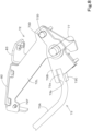
- the lever device 70 includes a base 71, a movable bracket 72, and a lever 73, as illustrated in FIGS. 3A and 3B .
- the base 71 and the movable bracket 72 are covered by the console cover 66.
- the first cover 66A covers the movable bracket 72 and the like and rotates together with the movable bracket 72.
- the lever 73 projects forward from the console cover 66.
- the right operating device 17R which is located rightward of the operator's seat 6, includes a console cover 74, an operating lever (right operating lever) 67R, a remote control valve (not shown), an armrest 69R, a dozer lever 75, and a plurality of switches 76.
- the console cover 74 covers the frame of the right operating device 17R.
- the frame of the right operating device 17R is attached directly or indirectly to the machine body 2.
- the right operating lever 67R is located at an upper front portion of the right operating device 17R and is capable of pivoting forward, backward, leftward, and rightward.
- the remote control valve is a pilot valve operated using the right operating lever 67R, located below the right operating lever 67R, and covered by the console cover 74.
- the armrest 69R is a member on which the operator's arm and other part(s) are placed, and is located behind the right operating lever 67R.
- the dozer lever 75 is used to operate the dozer device 7.
- the plurality of switches 76 are located at the top of the console cover 74 and used to operate devices provided in or on the working machine 1.
- the left operating lever 67L (remote control valve 68) can be used to operate two objects (hydraulic actuators) provided in or on the working machine 1.
- the left operating lever 67L can be used to operate the swivel motor to turn the machine body 2 (can be used to turn the machine body 2) and can be used to operate the arm cylinder C3 (can be used to swing the arm 12).
- the right operating lever 67R can also be used to operate two objects (hydraulic actuators) provided in or on the working machine 1.
- the right operating lever 67R can be used to operate the boom cylinder C2 (can be used to swing the boom 11) and can be used to operate the bucket cylinder C4 (can be used to swing the bucket 13).
- the lever 73 is an unloading lever (operation lock lever) to switch hydraulic actuator(s) of the working machine 1 between an operable state and an inoperable state.
- the lever device 70 is an unloading lever device (operation lock lever device) including the unloading lever. Therefore, the following description is based on the assumption that the lever device 70 is an unloading lever device and the lever 73 is an unloading lever.
- the lever device 70 is not limited to an unloading lever device and the lever 73 is not limited to an unloading lever.
- the lever 73 may be an operation lock lever to switch electric actuator(s) (not shown), provided in or on the working machine 1 instead of or in addition to the hydraulic actuator(s) described above, between operable and inoperable states.
- the lever 73 may also be an operation lock lever to output a signal, to a controller which controls the operation of actuator(s) provided in or on the working machine 1, to switch the actuator(s) between operable and inoperable states.
- the lever 73 is not limited to those for use in locking the operation of actuator(s), but may be the one that is used for other purposes.
- the base 71 is attached to a member 90 attached and secured to the machine body 2.
- the unloading lever 73 and the movable bracket 72 are supported on a support shaft 77 attached to the base 71 such that the unloading lever 73 and the movable bracket 72 are pivotable about an axis.
- the support shaft 77 is attached to the base 71 such that the support shaft 77 is not rotatable.
- the movable bracket 72 has attached thereto the left operating lever 67L, the remote control valve 68, and the armrest 69L.
- the unloading lever 73 and the movable bracket 72 can be repositioned in a lowered position P1 illustrated in FIG. 4A and a raised position P2 illustrated in FIG. 5A which is a position of the unloading lever 73 and the movable bracket 72 pivoted upward from the lowered position P1 about the support shaft 77.
- a raised position P2 illustrated in FIG. 5A which is a position of the unloading lever 73 and the movable bracket 72 pivoted upward from the lowered position P1 about the support shaft 77.
- the unloading lever 73 and the movable bracket 72 are in the raised position P2, for example, it is not possible to operate the working device 4 (boom cylinder C2, arm cylinder C3, bucket cylinder C4) or the machine body 2 (swivel motor).
- the unloading lever 73 and the movable bracket 72 are in the lowered position P1, it is possible to operate the working device 4 and turn the machine body 2.
- the unloading lever device 70 is described in detail.
- the unloading lever device 70 includes the base 71, the movable bracket 72, the unloading lever 73, and the support shaft 77 described above, as well as a position restrictor 78, a biasing member 79, a detection switch 80, and a cam member 81.
- the base 71 is made of plate(s) and includes a first side wall 71L which is a left side wall, a second side wall 71R which is a right side wall, and a connecting plate 71A that connects the first side wall 71L and the second side wall 71R at their lower portion.
- the connecting plate 71A is attached to the member 90 fixed to the machine body 2.
- the support shaft 77 is provided to span the gap between the first and second side walls 71L and 71R. The support shaft 77 is supported by the first and second side walls 71L and 71R and is attached to the first side wall 71L to be secured to the base 71.
- a first pivot portion 71B is provided at an upper portion of the first side wall 71L.
- a mounting stay 71C is fixed to the inner side of the second side wall 71R (fixed to the surface facing the first side wall 71L), and a position restrictor 78 is attached to the mounting stay 71C.
- the second side wall 71R has, at a position below the support shaft 77, an insertion slot 71D in the form of an arc centered on the axis of the support shaft 77.
- the movable bracket 72 is supported directly or indirectly on the base 71 such that movable bracket 72 projects forward from the upper portion of the base 71 when the unloading lever 73 and the movable bracket 72 are in the lowered position P1.
- the movable bracket 72 is provided, at a front portion thereof, with a valve mount 82 where the remote control valve 68 is mounted and a mounting stay 83 where the armrest 69L is attached.
- the movable bracket 72 is made of plate(s) and includes a first wall portion 72L which is a left side wall, a second wall portion 72R which is a right side wall, and a pair of connecting stays 72A and 72B that connect the first wall portion 72L and second wall portion 72R.
- a rear portion of the first wall portion 72L is located inward of an upper portion of the first side wall 71L, and a rear portion of the second wall portion 72R is located inward of the second side wall 71R.
- the support shaft 77 is inserted to span the gap between the first and second wall portions 72L and 72R.
- the first wall portion 72L is supported on the support shaft 77 such that the first wall portion 72L is pivotable about an axis, via a boss 72C which passes through the first wall portion 72L and is fixed to the first wall portion 72L by welding or other method.
- a bearing member 84 is attached to the outside of the second wall portion 72R (opposite the surface facing the first wall portion 72L).
- the second wall portion 72R is supported on the support shaft 77 via the bearing member 84 such that the second wall portion 72R is pivotable about an axis.
- the head of one (bolt 84A) of two bolts which attach the bearing member 84 is inserted in the insertion slot 71D and movable within the insertion slot 71D as the movable bracket 72 pivots about the support shaft 77.
- the pair of connecting stays 72A and 72B are located at a rear portion of the movable bracket 72 such that the support shaft 77 is located between the connecting stays 72A and 72B and the connecting stays 72A and 72B extend to span the gap between the first wall portion 72L and the second wall portion 72R.
- Each of the connecting stays 72A and 72B is provided with a first engagement portion 86. That is, in the present embodiment, a pair of the first engagement portions 86 are provided. Note that only a single first engagement portion 86 may be provided. In other words, it is only necessary to provide at least one first engagement portion 86.
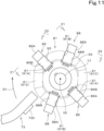
- the pair of first engagement portions 86 are arranged symmetrically to each other with respect to the center (axis X2) of the support shaft 77, as illustrated in FIG. 11 .
- Each first engagement portion 86 includes a shaft portion 86A fixed to the connecting stay 72A or 72B, and a roller 86B fitted on the outside of the shaft portion 86A such that the roller 83B is rotatable about the axis of the shaft portion 86A.
- the shaft portion 86A is fixed to the connecting stay 72A or 72B such that the shaft portion 86A projects from the connecting stay 72A or 72B toward the support shaft 77.
- the roller 86B is cylindrical in shape and is fitted to the shaft portion 86A between the connecting stay 72A or 72B and the support shaft 77.
- a guide slot 72D in the form of an arc centered on the axis of the support shaft 77 is provided at an upper rear portion of the first wall portion 72L.
- a contact member 72E is fixed to a rear portion of the second wall portion 72R.
- the contact member 72E contacts the position restrictor 78 on the base 71 to restrict the movable bracket 72 from pivoting in the upward direction D1.
- a second pivot portion 72F is provided at a front portion of the first wall portion 72L.
- the unloading lever 73 includes a lever body 73A, a lever base 73B, a contact stay 73C, and a pin 73D.
- a base 73a of the lever body 73A is inserted into a cutout 73b in the lever base 73B and secured to that lever base 73B by welding or some other method.
- the contact stay 73C is fixed directly or indirectly to the lower surface of the base 73a of the lever body 73A.
- the lever base 73B is located inward of the first wall portion 72L of the movable bracket 72.
- the lever base 73B is supported on the support shaft 77 via a boss portion 73E that passes through and is fixed to the lever base 73B by welding or some other method such that the lever base 73B is rotatable about the axis (see FIG. 10 ).
- a pair of support stays 87A and 87B are fixed to the opposite surface of the lever base 73B from the first wall portion 72L.
- the pair of support stays 87A and 87B are provided such that the support shaft 77 is located between them.
- Each of the support stays 87A and 87B is provided with a second engagement portion 88. That is, in the present embodiment, a pair of the second engagement portions 88 are provided. Note that only a single second engagement portion 88 may be provided. In other words, it is only necessary to provide at least one second engagement portion 88.
- the pair of second engagement portions 88 are arranged symmetrically to each other with respect to the center (axis) of the support shaft 77, as illustrated in FIG. 11 .
- Each second engagement portion 88 includes a shaft portion 88A fixed to the support stay 87A or 87B, and a roller 88B freely fitted on the outside of the shaft portion 88A such that the roller 88B is rotatable about the axis of the shaft portion 88A.
- the shaft portion 88A is fixed to the support stay 87A or 87B such that the shaft portion 88A projects from the support stay 87A or 87B toward the support shaft 77.
- the roller 88B is cylindrical in shape and is fitted on the shaft portion 88A between the support stay 87A or 87B and the support shaft 77.
- the pair of first engagement portions 86 (rollers 86B) and the pair of second engagement portions 88 (rollers 88B) are located on the same circumference centered on the axis X2 of the support shaft 77 (see FIG. 11 ).
- the pin 73D is inserted through the guide slot 72D in the first wall portion 72L.
- the pin 73D can move between a first end 72Da and a second end 72Db of the guide slot 72D as the unloading lever 73 pivots about the support shaft 77.
- the pin 73D may be provided on the first wall portion 72L and the guide slot 72D may be provided directly or indirectly in/on the unloading lever 73.
- the biasing member 79 includes a gas spring.
- the biasing member 79 is pivoted at a first end on the first pivot portion 71B and at a second end on the second pivot portion 72F.
- the biasing member 79 biases the movable bracket 72 in the upward direction D1.
- the detection switch 80 is a sensor to detect whether the unloading lever 73 (and the movable bracket 72) is in the lowered position P1 or in a position above the lowered position P1. As illustrated in FIG. 3A , the detection switch 80 is located at a front portion of the base 71 near the first side wall 71L, and is attached to the base 71. When the unloading lever 73 (and the movable bracket 72) is in the lowered position P1, the contact stay 73C on the unloading lever 73 presses a contact of the detection switch 80, so that the unloading lever 73 is detected as being in the lowered position P1. When the unloading lever 73 is pivoted from the lowered position P1 in the upward direction D1 and the pressure on the contact applied by the contact stay 73C is removed, the unloading lever 73 is detected as having been pivoted upward from the lowered position P1.
- the cam member 81 is attached to the support shaft 77 between the lever base 73B and the second wall portion 72R such that the cam member 81 is not rotatable about the axis but movable in the axial direction.
- a central wall 81A at a central portion of the cam member 81 has an insertion hole 81B through which the support shaft 77 is inserted in the axial direction (machine body width direction).
- a key 89 that fits into a keyway 77A in the support shaft 77 is inserted in the insertion slot 81C.
- cam member 81 This allows the cam member 81 to be not rotatable about the axis of the support shaft 77 and movable in the axial direction of the support shaft 77. Note that key connection does not need to be used to allow the cam member 81 to be not rotatable about the axis of the support shaft 77 and movable in the axial direction of the support shaft 77.
- elements may be arranged such that a slide plate projects from the end face (right end face) 81D facing the second wall portion 72R of the cam member 81 along the support shaft 77 and a slide plate projects also from the second wall portion 72R along the support shaft 77, the plate surfaces of these slide plates are slidably brought into contact with each other, so that the cam member 81 is not rotatable about the axis of the support shaft 77 and movable in the axial direction of the support shaft 77.
- Elements may be arranged such that the support shaft 77 and the central wall 81A of the cam member 81 are splined, so that the cam member 81 is not rotatable about the axis of the support shaft 77 and movable in the axial direction of the support shaft 77.
- the cam member 81 is an end cam which includes a cylinder having recesses at an outer peripheral portion of an end face thereof.
- the recesses (engagement recesses 91) in the cam member 81 i.e., a plurality of engagement recess 91, are in the surface facing the lever base 73B (left surface) of an outer wall 81E of the cam member 81.
- the engagement recesses 91 receive the first engagement portions 86 and the second engagement portions 88 (have the first engagement portions 86 and the second engagement portions 88 fitted therein (engaged therewith)).
- FIG. 11 illustrates the surface of the cam member 81 engaged with the first engagement portions 86 and the second engagement portions 88 when the unloading lever 73 and the movable bracket 72 are in the lowered position P1.
- FIG. 12 illustrates the surface of the cam member 81 engaged with the first engagement portions 86 and the second engagement portions 88 when the unloading lever 73 and the movable bracket 72 in the raised position P2. As illustrated in FIGS. 11 and 12 , the first engagement portions 86 (rollers) and the second engagement portions 88 (rollers) are fitted in the engagement recesses 91.
- the cam member 81 includes the engagement recesses 91 to receive the first engagement portions 86 and the second engagement portions 88 when the unloading lever 73 and the movable bracket 72 are in the lowered position P1 and when the unloading lever 73 and the movable bracket 72 are in the raised position P2.
- the engagement recesses 91 include first engagement recess(es) 91A, second engagement recess(es) 91B, and third engagement recess(es) 91C.
- a pair of the first engagement recesses 91A, a pair of the second engagement recesses 91B, and a pair of the third engagement recesses 91C are provided such that each pair corresponds to a pair of the first engagement portions 86 or a pair of the second engagement portions 88.
- first engagement recess 91A, a single second engagement recess 91B, and a single third engagement recess 91C are provided.
- the first engagement recesses 91A receive the first engagement portions 86 (rollers 86B)
- the second engagement recesses 91B receive the second engagement portions 88 (rollers 88B)
- the third engagement recesses 91C do not receive the first engagement portions 86 (rollers 86B) or the second engagement portions 88 (rollers 88B).
- the first engagement recesses 91A do not receive the first engagement portions 86 (rollers 86B) or the second engagement portions 88 (rollers 88B)
- the second engagement recesses 91B receive the first engagement portions 86 (rollers 86B)
- the third engagement recesses 91C receive the second engagement portions 88 (rollers 88B).
- the second engagement recesses 91B are used both as engagement recesses to receive the first engagement portions 86 and engagement recesses to receive the second engagement portions 88. Since some engagement recesses also function as different engagement portions, the cam member 81 (unloading lever device 70) can be made smaller and simpler.
- engagement recesses to receive the first engagement portions 86 when the unloading lever 73 and the movable bracket 72 are in the raised position P2 may be provided separately from the second engagement recesses 91B.
- two engagement recesses may be provided for one first engagement portion 86
- two engagement recesses may be provided for one second engagement portion 88. That is, in the present embodiment, three engagement recesses are provided for one first engagement portion 86 and one second engagement portion 88, but four engagement recesses may be provided for one first engagement portion 86 and one second engagement portion 88.
- a biasing member 92 is provided between the cam member 81 and the second wall portion 72R.
- the biasing member 92 biases the cam member 81 in the direction that allows the cam member 81 to engage with the first engagement portions 86 and the second engagement portions 88.
- the biasing member 92 includes a coil spring and is positioned to be wound around the outer circumference of the support shaft 77.
- the biasing member 92 (coil spring) is placed in a compressed manner between the end face 81D of the cam member 81 and the bearing member 84, a first end of the biasing member 92 is in contact with the end face 81D of the cam member 81, and a second end of the biasing member 92 is in contact with the bearing member 84. Note that the second end of the biasing member 92 may be in contact with the second wall portion 72R.
- the engagement surface (first engagement surface 91a) of each engagement recess 91A that engages with (contacts) a portion 86a at an end of a corresponding first engagement portion 86 functions as a pivot restrictor surface 93 which does not allow the movable bracket 72 to pivot even when the movable bracket 72 is about to be forcibly pivoted in the upward direction D1 (which does not allow the first engagement portion 86 to leave the first engagement recess 91A).
- the pivot restrictor surface 93 is a surface that restricts the movable bracket 72 from pivoting.
- the first engagement portion 86 restricts the movable bracket 72 from pivoting in the upward direction D1 by engaging with the cam member 81 (first engagement recess 91A) when the unloading lever 73 and the movable bracket 72 are in the lowered position P1.
- the pivot restrictor surface 93 is a surface orthogonal to the circumferential direction of the cam member 81 or a sloping surface sloping toward the opening of the recess in the upward direction D1, and is inclined at an angle that can prevent the movable bracket 72 (first engagement portion 86) from pivoting.
- engagement surface (second engagement surface 91b) on the opposite side of the first engagement recess 91A from the first engagement surface 91a (opposite side in the circumferential direction of the cam member 81) also functions as a pivot restrictor surface 93.
- each second engagement recess 91B that engages with (contacts) a portion 88a at an end of a corresponding second engagement portion 88 (i.e., the portion that faces in the upward direction D1) functions as a cam surface 94 which allows, when the unloading lever 73 is pivoted in the upward direction D1, the second engagement portion 88 to slide to cause the cam member 81 to move against the biasing force of the biasing member 92.
- the cam surface 94 is a sloping surface sloping toward the opening of the recess in the upward direction D1, and is a gently sloping surface that allows the cam member 81 to move against the biasing force of the biasing member 92 when the unloading lever 73 is pivoted to push the second engagement portion 88 against the sloping surface.
- the angle of inclination of the cam surface 94 is, for example, but not limited to, about 45°.
- the engagement surface (fourth engagement surface 91d) of the second engagement recess 91B on the opposite side from the third engagement surface 91c (opposite side in the circumferential direction of the cam member 81) functions as a pivot restrictor surface 93.
- the engagement recess 91 that receives the first engagement portion 86 has the pivot restrictor surface 93 which restricts the movable bracket 72 from pivoting by contacting the first engagement portion 86.
- the engagement recess 91 that receives the second engagement portion 88 has the cam surface 94 on which the second engagement portion 88 slides such that the cam member 81 moves against the biasing force of the biasing member 92 when the second engagement portion 88 pivots together with the unloading lever 73.
- the unloading lever device 70 is such that, when the movable bracket 72 and the unloading lever 73 are in the lowered position P1, as illustrated in FIG. 12 , each first engagement portion 86 engages with a corresponding second engagement surface 91b (pivot restrictor surface 93) to restrict the movable bracket 72 from pivoting downward, and, as illustrated in FIG. 13 , each second engagement portion 88 engages with a corresponding fourth engagement surface 91d (pivot restrictor surface 93) to restrict the unloading lever 73 from pivoting downward. This restricts the movable bracket 72 and the unloading lever 73 from pivoting downward from the lowered position P1.
- each first engagement portion 86 engages with (contacts) a corresponding pivot restrictor surface 93 (first engagement surface 91a) of a corresponding first engagement recess 91A and the movable bracket 72 does not pivot, so that the unloading lever 73 pivots relative to the movable bracket 72 when pivoting upward from the lowered position P1.
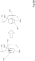
- the pin 73D is at the first end 72Da of the guide slot 72D, as illustrated in the left portion of FIG.
- each first engagement recess 91A disengages from a corresponding first engagement portion 86, resulting in disengagement between the first engagement portions 86 and the first engagement recesses 91A, as shown by the dot-dot-dash line in FIG. 12 .
- the movable bracket 72 is allowed to pivot in the upward direction D1.
- the pin 73D is located at the second end 72Db of the guide slot 72D.
- the unloading lever 73 pivots relative to the movable bracket 72 while the first engagement portions 86 and the cam member 81 (first engagement recess 91A) are about to be disengaged, and pivots together with the movable bracket 72 after the first engagement portions 86 and the cam member 81 are disengaged.
- the movable bracket 72 When the unloading lever 73 is pivoted from the lowered position P1 in the upward direction D1 to pivot the movable bracket 72 to the raised position P2, the movable bracket 72 may be pivoted by the unloading lever 73, but in the present embodiment, when the movable bracket 72 is pivoted from the lowered position P1 to the raised position P2, the movable bracket 72 is pivoted by the biasing force of the gas spring 79 in the upward direction D1.
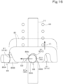
- each first engagement portion 86 fits into a corresponding second engagement recess 91B and each second engagement portion 88 fits into a corresponding third engagement recess 91C, as illustrated in FIG. 14 .
- the movable bracket 72 is restricted from pivoting in the upward direction D1 by the contact member 72E contacting the position restrictor 78, and the unloading lever 73 is restricted from pivoting in the upward direction D1 because the pin 73D is at the second end 72Db of the guide slot 72D.
- each first engagement portion 86 engages with (contacts) a corresponding fourth engagement surface 91d (pivot restrictor surface 93), so that the movable bracket 72 does not pivot in the downward direction D2 even when the movable bracket 72 is about to be pivoted in the downward direction D2.
- each third engagement recess 91C that engages with (contacts) a portion 88b at an end of a corresponding second engagement portion 88 (i.e., the portion that faces in the downward direction D2) functions as a cam surface 94.
- the cam surface 94 of the third engagement recess 91C is a sloping surface sloping toward the opening of the recess in the downward direction D2, and is a gentle sloping surface that allows the cam member 81 to move against the biasing force of the biasing member 92 by forcing the unloading lever 73 to pivot and pressing the second engagement portion 88 against the surface.
- the engagement surface (46 engagement surface 91f) on the opposite side of the third engagement recess 91C from the fifth engagement surface 91e (opposite side in the circumferential direction of the cam member 81) functions as a pivot restrictor surface 93.
- each first engagement portion 86 engages with (contacts) a corresponding fourth engagement surface 91d (pivot restrictor surface 93) of a corresponding second engagement recess 91B and the movable bracket 72 does not pivot, so that the unloading lever 73 pivots relative to movable bracket 72 when pivoting downward from the raised position P2.
- the pin 73D is at the second end 72Db of the guide slot 72D as illustrated in the left portion of FIG.
- each second engagement recess 91B disengages from a corresponding first engagement portion 86, resulting in disengagement between the first engagement portions 86 and the second engagement recesses 91B, as indicated by dot-dot-dash line in FIG. 15 .
- the movable bracket 72 is allowed to pivot in the downward direction D2.
- the unloading lever 73 pivots relative to the movable bracket 72 while the first engagement portions 86 and the cam member 81 (second engagement recess 91B) are about to be disengaged, and pivots together with the movable bracket 72 after the first engagement portions 86 and the cam member 81 are disengaged.
- the unloading lever 73 When the unloading lever 73 is pivoted from the lowered position P1 in the upward direction D1 to pivot the movable bracket 72 to the raised position P2, the movable bracket 72 is pivoted in the upward direction D1 by the biasing force of the gas spring 79, but when the unloading lever 73 is pivoted downward from the raised position P2 to pivot the movable bracket 72 to the lowered position P1, the unloading lever 73 causes the movable bracket 72 to pivot. That is, the force to pivot the unloading lever 73 downward is transmitted to the movable bracket 72 via the pin 73D, which pushes the movable bracket 72 down against the biasing force of the gas spring 79.
- the mechanism in the present embodiment is configured such that the movable bracket 72 and the unloading lever 73 are pivotably supported on a single support shaft 77, and that the cam member 81, which engages with and disengages from the first engagement portions 86 on the movable bracket 72 and the second engagement portions 88 on the unloading lever 73, is attached to the support shaft 77, so that the movable bracket 72 is restricted to the lowered position P1 and the raised position P2 and such position restriction is released by pivoting the unloading lever 73 to allow the movable bracket 72 to pivot.
- This makes it possible to reduce the size and weight of the unloading lever device (lever device) 70. Therefore, a small biasing force of the gas spring 79 will suffice, making it possible to reduce the operating force of the unloading lever 73.
- a lever device (unloading lever device) 70 includes a base 71, a support shaft 77 provided on the base 71, a movable bracket 72 and a lever 73 which are supported on the support shaft 77 such that the movable bracket 72 and the lever 73 are pivotable between a lowered position P1 and a raised position P2, the raised position P2 being a position of the movable bracket 72 and the lever 73 pivoted upward from the lowered position P1, at least one first engagement portion 86 provided on the movable bracket 72, at least one second engagement portion 88 provided on the lever 73, a cam member 81 to engage with the at least one first engagement portion 86 and the at least one second engagement portion 88, the cam member 81 being attached to the support shaft 77 such that the cam member 81 is movable in a direction of an axis of the support shaft but not rotatable about the axis of the support shaft 77, and a biasing member 92 to bias the cam member 81 in
- This provides a mechanism in which the movable bracket 72 and the lever 73 are pivotally supported on the support shaft 77, the movable bracket 72 is provided with the at least one first engagement portion 86, the lever 73 is provided with the at least one second engagement portion 88, and the support shaft 77 has attached thereto the cam member 81 which engages with and disengages from the at least one first engagement portion 86 and the at least one second engagement portion 88 , so that the movable bracket 72 is restricted to the lowered position P1 and the raised position P2 and such position restriction is released by pivoting the lever 73 to allow the movable bracket 72 to pivot.
- This makes it possible to reduce the size and weight of the lever device 70.
- the cam member 81 includes engagement recesses 91 to receive the at least one first engagement portion 86 and the at least one second engagement portion 88 when the movable bracket and the lever are in the lowered position P1 and when the movable bracket and the lever are in the raised position P2.
- At least one of the engagement recesses 91 that receives the at least one first engagement portion 86 includes a pivot restrictor surface 93 to contact the at least one first engagement portion 86 to restrict the movable bracket 72 from pivoting.
- At least one of the engagement recesses 91 that receives the at least one second engagement portion 88 includes a cam surface 94 to allow the at least one second engagement portion 88 to slide thereon such that the cam member 81 moves against the biasing member 92 when the at least one second engagement portion 88 pivots together with the lever 73.
- the engagement recesses 91 include at least one first engagement recess 91A to receive the at least one first engagement portion 86 when the movable bracket and the lever are in the lowered position P1, at least one second engagement recess 91B to receive the at least one second engagement portion 88 when the movable bracket and the lever are in the lowered position P1, and at least one third engagement recess 91C which does not receive the at least one first engagement portion 86 or the at least one second engagement portion 88 when the movable bracket and the lever are in the lowered position P1.
- the at least one second engagement recess 91B receives the at least one first engagement portion 86 and the at least one third engagement recess 91C receives the at least one second engagement portion 88.
- the lever device includes a pair of the first engagement portions 86 and a pair of the second engagement portions 88.
- the pair of first engagement portions 86 are arranged symmetrically to each other with respect to a center X2 of the support shaft.
- the pair of second engagement portions 88 are arranged symmetrically to each other with respect to the center of the support shaft 77.
- the lever 73 pivots relative to the movable bracket 72 while the at least one first engagement portion 86 and the cam member 81 are about to be disengaged, and pivots together with the movable bracket 72 after the at least one first engagement portion 86 and the cam member 81 are disengaged.
- the lever device further includes a guide slot 72D in one of the movable bracket 72 and the lever 73, and a pin 73D provided on the other of the movable bracket 72 and the lever 73 and inserted in the guide slot 72D.
- the guide slot 72D is in the form of an arc centered on the axis of the support shaft 77.
- the lever 73 pivots relative to the movable bracket 72 while the pin 73D is moving between a first end 72Da and a second end 72Db of the guide slot 72D, and the movable bracket 72 pivots together with the lever 73 when the pin 73D is positioned at the first end 72Da or the second end 72Db of the guide slot 72D.
- the lever device 70 may be provided in or on the working machine 1.
- the lever 73 may be an operation lock lever (unloading lever 73) to switch one or more actuators in or on the working machine 1 between an operable state and an inoperable state.
Landscapes
- Engineering & Computer Science (AREA)
- Mining & Mineral Resources (AREA)
- Civil Engineering (AREA)
- General Engineering & Computer Science (AREA)
- Structural Engineering (AREA)
- Physics & Mathematics (AREA)
- General Physics & Mathematics (AREA)
- Automation & Control Theory (AREA)
- Mechanical Engineering (AREA)
- Mechanical Control Devices (AREA)
- Component Parts Of Construction Machinery (AREA)
Abstract
Description
- The present invention relates to a lever device and a working machine.
- A lever device disclosed in
Patent Literature 1 is known. - The lever device disclosed in
Patent Literature 1 is configured such that a movable bracket is supported on a first support shaft provided on a fixed base such that the movable bracket is rotatable between a lowered position and a raised position which is a position of the movable bracket pivoted upward from the lowered position, a lever is pivotally supported on a second support shaft on the movable bracket, and moving up or down the lever causes the movable bracket to move between the lowered position and the raised position. - PTL1:
Japanese Unexamined Patent Application Publication No. 2019-116753 - The lever device disclosed in
Patent Literature 1 is large in size because the center of rotation of the lever and the center of rotation of the movable bracket differ from each other and therefore the two support shafts are required, and also because the lever device requires a mechanism between the first support shaft and the second support shaft to restrict the position of the movable bracket to the lowered position and raised position and to stop restricting the position and allow the movable bracket to pivot upon the pivoting of the lever. Furthermore, the lever device is heavy, requiring a large operating force. - In view of such problems, an object of the present invention is to reduce the size and weight of the lever device.
- A lever device according to an aspect of the present invention includes a base, a support shaft provided on the base, a movable bracket and a lever which are supported on the support shaft such that the movable bracket and the lever are pivotable between a lowered position and a raised position, the raised position being a position of the movable bracket and the lever pivoted upward from the lowered position, at least one first engagement portion provided on the movable bracket, at least one second engagement portion provided on the lever, a cam member to engage with the at least one first engagement portion and the at least one second engagement portion, the cam member being attached to the support shaft such that the cam member is movable in a direction of an axis of the support shaft but not rotatable about the axis of the support shaft, and a biasing member to bias the cam member in a direction that allows the cam member to engage with the at least one first engagement portion and the at least one second engagement portion, wherein the at least one first engagement portion is configured to, when the movable bracket and the lever are in the lowered position and when the movable bracket and the lever are in the raised position, engage with the cam member to restrict the movable bracket from pivoting, and the at least one second engagement portion is configured such that, when the lever is caused to pivot upward from the lowered position or pivot downward from the raised position, the at least one second engagement portion causes the cam member to move against the biasing member to disengage the cam member from the at least one first engagement portion.
- The cam member includes engagement recesses to receive the at least one first engagement portion and the at least one second engagement portion when the movable bracket and the lever are in the lowered position and when the movable bracket and the lever are in the raised position. At least one of the engagement recesses that receives the at least one first engagement portion includes a pivot restrictor surface to contact the at least one first engagement portion to restrict the movable bracket from pivoting. At least one of the engagement recesses that receives the at least one second engagement portion includes a cam surface to allow the at least one second engagement portion to slide thereon such that the cam member moves against the biasing member when the at least one second engagement portion pivots together with the lever.
- The engagement recesses include at least one first engagement recess to receive the at least one first engagement portion when the movable bracket and the lever are in the lowered position, at least one second engagement recess to receive the at least one second engagement portion when the movable bracket and the lever are in the lowered position, and at least one third engagement recess which does not receive the at least one first engagement portion or the at least one second engagement portion when the movable bracket and the lever are in the lowered position. When the movable bracket and the lever are in the raised position, the at least one second engagement recess receives the at least one first engagement portion and the at least one third engagement recess receives the at least one second engagement portion.
- The lever device includes a pair of the first engagement portions and a pair of the second engagement portions. The pair of first engagement portions are arranged symmetrically to each other with respect to a center of the support shaft. The pair of second engagement portions are arranged symmetrically to each other with respect to the center of the support shaft.
- The lever pivots relative to the movable bracket while the at least one first engagement portion and the cam member are about to be disengaged, and pivots together with the movable bracket after the at least one first engagement portion and the cam member are disengaged.
- The lever device further includes a guide slot in one of the movable bracket and the lever, and a pin provided on the other of the movable bracket and the lever and inserted in the guide slot. The guide slot is in the form of an arc centered on the axis of the support shaft. The lever pivots relative to the movable bracket while the pin is moving between a first end and a second end of the guide slot, and the movable bracket pivots together with the lever when the pin is positioned at the first end or the second end of the guide slot.
- A working machine according to an aspect of the present invention includes the lever device.
- The lever is an operation lock lever to switch one or more actuators in or on the working machine between an operable state and an inoperable state.
- The above configuration provides a mechanism in which a movable bracket and a lever are pivotally supported on a support shaft, the movable bracket is provided with first engagement portion(s), the lever is provided with second engagement portion(s), and the support shaft has attached thereto a cam member which engages with and disengages from the first engagement portion(s) and the second engagement portion(s), so that the movable bracket is restricted to the lowered position and the raised position and such position restriction is released by pivoting the lever to allow the movable bracket to pivot. This makes it possible to reduce the size and weight of the lever device.
-
- [
FIG. 1] FIG. 1 is a side view of a working machine. - [
FIG. 2] FIG. 2 is a perspective view of an operator's seat and its surroundings. - [
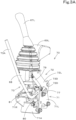
FIG. 3A] FIG. 3A is a perspective view of a front side of a lever device. - [
FIG. 3B] FIG. 3B is a perspective view of a rear side of the lever device. - [
FIG. 3C] FIG. 3C is an exploded perspective view of the lever device. - [
FIG. 4A] FIG. 4A is a side view of the lever device in a lowered position. - [
FIG. 4B] FIG. 4B shows side views illustrating the movement of a pin during transition from the lowered position to a raised position. - [
FIG. 5A] FIG. 5A is a side view of the lever device in the raised position. - [
FIG. 5B] FIG. 5B shows side views illustrating the movement of the pin during transition from the raised position to the lowered position. - [
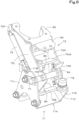
FIG. 6] FIG. 6 is a left rear perspective view showing the relationship between a base and a movable bracket. - [
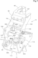
FIG. 7] FIG. 7 is a right rear perspective view showing the relationship between the base and the movable bracket. - [
FIG. 8] FIG. 8 is a left side perspective view showing the relationship between the movable bracket and a lever. - [
FIG. 9] FIG. 9 is a right side perspective view showing the relationship between the movable bracket and the lever. - [
FIG. 10] FIG. 10 is a rear cross-sectional view of a cam member and its surroundings. - [
FIG. 11] FIG. 11 is a side view of the cam member, first engagement portions, and second engagement portions when the movable bracket and the lever are in the lowered position. - [
FIG. 12] FIG. 12 shows a view on arrow Z1, Z1 ofFIG. 11 . - [
FIG. 13] FIG. 13 shows a view on arrow Z2, Z2 ofFIG. 11 . - [
FIG. 14] FIG. 14 is a side view of the cam member, the first engagement portions, and the second engagement portions when the movable bracket and the lever are in the raised position. - [
FIG. 15] FIG. 15 shows a view on arrow Z3, Z3 ofFIG. 14 . - [
FIG. 16] FIG. 16 shows a view on arrow Z4, Z4 ofFIG. 14 . - The following description discusses an embodiment of the present invention with reference to drawings as necessary.
-
FIG. 1 is a side view schematically illustrating a general configuration of a workingmachine 1 according to the present embodiment. In the present embodiment, a backhoe which is a swiveling working machine is illustrated as an example of the workingmachine 1. - As illustrated in
FIG. 1 , the workingmachine 1 includes a machine body (swivel base) 2, a travelingdevice 3, and a workingdevice 4. Themachine body 2 is provided with an operator'sseat 6 on which an operator (driver) is to be seated. - In the present embodiment, a forward direction from the operator seated on the operator's
seat 6 of the working machine 1 (direction indicated by arrow A1 inFIG. 1 ) is referred to as a forward direction (machine body forward direction), a rearward direction from the operator (direction indicated by arrow A2 inFIG. 1 ) is referred to as a rearward direction (machine body rearward direction), and a direction indicated by arrow K1 inFIG. 1 is referred to as a front-rear direction (machine body front-rear direction). A leftward direction from the operator (direction toward the near size inFIG. 1 ) is referred to as a leftward direction, and a rightward direction from the operator (direction toward the far side inFIG. 1 ) is referred to as a rightward direction. - A horizontal direction orthogonal to the front-rear direction K1 is referred to as a machine body width direction. A direction rightward or leftward from the widthwise center of the
machine body 2 is referred to as a machine body width outward direction. That is, the machine body width outward direction is a direction going away from the widthwise center of themachine body 2 along the machine body width direction. A direction opposite to the machine body width outward direction is referred to as a machine body width inward direction. That is, the machine body width inward direction is a direction approaching the widthwise center of themachine body 2 along the machine body width direction. - As illustrated in
FIG. 1 , the travelingdevice 3 is a crawler traveling device to support themachine body 2 such that themachine body 2 is allowed to travel, and includes atravel frame 3A, afirst traveling device 3L provided on the left side of thetravel frame 3A, and asecond traveling device 3R provided on the right side of thetravel frame 3A. Thefirst traveling device 3L and thesecond traveling device 3R are driven by travel motor(s) M1 including hydraulic motor(s) (hydraulic actuator(s)). In the present embodiment, the travelingdevice 3 is acrawler traveling device 3, but this does not imply any limitation. The travelingdevice 3 may be awheel traveling device 3. The travelingdevice 3 has attached to a front portion thereof adozer device 7. Thedozer device 7 can be driven by a dozer cylinder including a hydraulic cylinder (hydraulic actuator). - As illustrated in
FIG. 1 , themachine body 2 is supported on the travelingdevice 3 via a swivel bearing 8 such that themachine body 2 is rotatable about a rotational axis X1 which is an axis extending in an up-and-down direction. Themachine body 2 is provided, at a front portion thereof, with asupport bracket 9 and aswing bracket 10 to support the workingdevice 4. Thesupport bracket 9 projects forward from themachine body 2. Theswing bracket 10 is attached to a front portion of thesupport bracket 9 such that theswing bracket 10 is swingable about a vertical axis (axis extending in the up-and-down direction). - As illustrated in
FIG. 1 , the workingdevice 4 includes aboom 11, anarm 12, and abucket 13. The proximal portion of theboom 11 is attached to an upper portion of theswing bracket 10 such that theboom 11 is swingable about a lateral axis (axis extending along the machine body width direction). Thearm 12 is attached to the distal portion of theboom 11 such that thearm 12 is swingable about a lateral axis. Thebucket 13 is provided at the distal portion of thearm 12 such that thebucket 13 is capable of shoveling and dumping. The shoveling refers to a swinging movement of thebucket 13 toward theboom 11, and is, for example, performed to scoop earth and sand or the like. The dumping refers to a swinging movement of thebucket 13 away from theboom 11, and is, for example, performed to drop (discharge) the scooped sand or the like. - The working
machine 1 can have attached thereto, instead of or in addition to thebucket 13, some other working tool (hydraulic attachment) which can be driven by a hydraulic actuator. Examples of the other working tool include hydraulic breakers, hydraulic crushers, angle brooms, earth augers, pallet forks, sweepers, mowers, and snow blowers. - The
swing bracket 10 is swingable upon extension and retraction of a swing cylinder (not illustrated). Theboom 11 is swingable upon extension and retraction of the boom cylinder C2. Thearm 12 is swingable upon extension or retraction of an arm cylinder C3. Thebucket 13 is capable of shoveling and dumping upon extension and retraction of a bucket cylinder C4. The swing cylinder, the boom cylinder C2, the arm cylinder C3, and the bucket cylinder C4 are each a hydraulic cylinder (hydraulic actuator). - As illustrated in
FIG. 1 , a prime mover E1 is provided at a rear portion of themachine body 2. The prime mover E1 is a diesel engine. Note that the prime mover E1 may be a gasoline engine, an electric motor, or a hybrid prime mover including an engine and an electric motor. On themachine body 2, anoperator portion 18 is provided forward of the prime mover E1. Theoperator portion 18 includes the operator'sseat 6, a travelinglever 16 located forward of the operator'sseat 6, an operating device (left operating device) 17L provided leftward of the operator'sseat 6, an operating device (right operating device) 17R provided rightward of the operator'sseat 6, and/or the like. The travelinglever 16 is an operation member (manual operator) to operate the travelingdevice 3. Theoperating devices boom 11 to swing, cause thearm 12 to swing, cause thebucket 13 to shovel and dump, and/or cause themachine body 2 to rotate. Themachine body 2 is provided with astep 21 which defines a floor surface at the top surface thereof and in front of the operator'sseat 6. - As illustrated in
FIGS. 2 and3A , theleft operating device 17L, which is located leftward of the operator'sseat 6, includes aconsole cover 66, an operating lever (left operating lever) 67L, aremote control valve 68, anarmrest 69L, and alever device 70. - The
console cover 66 includes afirst cover 66A and asecond cover 66B. Theleft operating lever 67L is located at an upper front portion of theleft operating device 17L and is capable of pivoting forward, backward, leftward and rightward. Theremote control valve 68 is a pilot valve operated using theleft operating lever 67L, and is located below theleft operating lever 67L. Theremote control valve 68 is housed in thefirst cover 66A. Thearmrest 69L is a member on which the operator's arm and other part(s) are placed, and is located behind theleft operating lever 67L. - The
lever device 70 includes abase 71, amovable bracket 72, and alever 73, as illustrated inFIGS. 3A and3B . - As illustrated in
FIG. 2 , thebase 71 and themovable bracket 72 are covered by theconsole cover 66. Thefirst cover 66A covers themovable bracket 72 and the like and rotates together with themovable bracket 72. Thelever 73 projects forward from theconsole cover 66. - As illustrated in
FIG. 2 , theright operating device 17R, which is located rightward of the operator'sseat 6, includes aconsole cover 74, an operating lever (right operating lever) 67R, a remote control valve (not shown), anarmrest 69R, adozer lever 75, and a plurality ofswitches 76. - The
console cover 74 covers the frame of theright operating device 17R. The frame of theright operating device 17R is attached directly or indirectly to themachine body 2. Theright operating lever 67R is located at an upper front portion of theright operating device 17R and is capable of pivoting forward, backward, leftward, and rightward. The remote control valve is a pilot valve operated using theright operating lever 67R, located below theright operating lever 67R, and covered by theconsole cover 74. Thearmrest 69R is a member on which the operator's arm and other part(s) are placed, and is located behind theright operating lever 67R. Thedozer lever 75 is used to operate thedozer device 7. The plurality ofswitches 76 are located at the top of theconsole cover 74 and used to operate devices provided in or on the workingmachine 1. - The
left operating lever 67L (remote control valve 68) can be used to operate two objects (hydraulic actuators) provided in or on the workingmachine 1. For example, theleft operating lever 67L can be used to operate the swivel motor to turn the machine body 2 (can be used to turn the machine body 2) and can be used to operate the arm cylinder C3 (can be used to swing the arm 12). - The
right operating lever 67R can also be used to operate two objects (hydraulic actuators) provided in or on the workingmachine 1. For example, theright operating lever 67R can be used to operate the boom cylinder C2 (can be used to swing the boom 11) and can be used to operate the bucket cylinder C4 (can be used to swing the bucket 13). - The following description first schematically discusses the
lever device 70 according to the present embodiment. - The
lever 73 is an unloading lever (operation lock lever) to switch hydraulic actuator(s) of the workingmachine 1 between an operable state and an inoperable state. Thelever device 70 is an unloading lever device (operation lock lever device) including the unloading lever. Therefore, the following description is based on the assumption that thelever device 70 is an unloading lever device and thelever 73 is an unloading lever. However, thelever device 70 is not limited to an unloading lever device and thelever 73 is not limited to an unloading lever. For example, thelever 73 may be an operation lock lever to switch electric actuator(s) (not shown), provided in or on the workingmachine 1 instead of or in addition to the hydraulic actuator(s) described above, between operable and inoperable states. Thelever 73 may also be an operation lock lever to output a signal, to a controller which controls the operation of actuator(s) provided in or on the workingmachine 1, to switch the actuator(s) between operable and inoperable states. Thelever 73 is not limited to those for use in locking the operation of actuator(s), but may be the one that is used for other purposes. - As illustrated in
FIG. 4A , thebase 71 is attached to amember 90 attached and secured to themachine body 2. The unloadinglever 73 and themovable bracket 72 are supported on asupport shaft 77 attached to the base 71 such that the unloadinglever 73 and themovable bracket 72 are pivotable about an axis. Thesupport shaft 77 is attached to the base 71 such that thesupport shaft 77 is not rotatable. Themovable bracket 72 has attached thereto theleft operating lever 67L, theremote control valve 68, and thearmrest 69L. - The unloading
lever 73 and themovable bracket 72 can be repositioned in a lowered position P1 illustrated inFIG. 4A and a raised position P2 illustrated inFIG. 5A which is a position of the unloadinglever 73 and themovable bracket 72 pivoted upward from the lowered position P1 about thesupport shaft 77. When the unloadinglever 73 and themovable bracket 72 are in the raised position P2, for example, it is not possible to operate the working device 4 (boom cylinder C2, arm cylinder C3, bucket cylinder C4) or the machine body 2 (swivel motor). When the unloadinglever 73 and themovable bracket 72 are in the lowered position P1, it is possible to operate the workingdevice 4 and turn themachine body 2. - Note that the following configuration may be used: when the unloading
lever 73 and themovable bracket 72 are in the raised position P2, all or major hydraulic actuators of the working machine 1 (such as the boom cylinder C2, the arm cylinder C3, the bucket cylinder C4, the swing cylinder, the dozer cylinder, the travel motor M1, the swivel motor, and/or hydraulic actuator(s) detachably connected to service port(s)) cannot be operated, i.e., no hydraulic fluid is supplied to them. - In the following description, the direction (direction indicated by arrow D1 in
FIG. 4A ) in which the unloadinglever 73 and themovable bracket 72 pivot upward from the lowered position P1 is referred to as upward direction D1, and the direction (direction indicated by arrow D2 inFIG. 5B ) in which the unloadinglever 73 and themovable bracket 72 pivot downward from the raised position P2 is referred to as downward direction D2. Next, the unloadinglever device 70 is described in detail. - As illustrated in
FIGS. 3A ,3B , and3C , the unloadinglever device 70 includes thebase 71, themovable bracket 72, the unloadinglever 73, and thesupport shaft 77 described above, as well as a position restrictor 78, a biasingmember 79, adetection switch 80, and acam member 81. - As illustrated in
FIGS. 6 and7 , thebase 71 is made of plate(s) and includes afirst side wall 71L which is a left side wall, asecond side wall 71R which is a right side wall, and a connectingplate 71A that connects thefirst side wall 71L and thesecond side wall 71R at their lower portion. The connectingplate 71A is attached to themember 90 fixed to themachine body 2. Thesupport shaft 77 is provided to span the gap between the first andsecond side walls support shaft 77 is supported by the first andsecond side walls first side wall 71L to be secured to thebase 71. Afirst pivot portion 71B is provided at an upper portion of thefirst side wall 71L. A mountingstay 71C is fixed to the inner side of thesecond side wall 71R (fixed to the surface facing thefirst side wall 71L), and a position restrictor 78 is attached to the mountingstay 71C. Thesecond side wall 71R has, at a position below thesupport shaft 77, aninsertion slot 71D in the form of an arc centered on the axis of thesupport shaft 77. - As illustrated in
FIG. 4A , themovable bracket 72 is supported directly or indirectly on the base 71 such thatmovable bracket 72 projects forward from the upper portion of the base 71 when the unloadinglever 73 and themovable bracket 72 are in the lowered position P1. Themovable bracket 72 is provided, at a front portion thereof, with avalve mount 82 where theremote control valve 68 is mounted and a mountingstay 83 where thearmrest 69L is attached. - As illustrated in
FIGS. 6 and7 , themovable bracket 72 is made of plate(s) and includes afirst wall portion 72L which is a left side wall, asecond wall portion 72R which is a right side wall, and a pair of connectingstays first wall portion 72L andsecond wall portion 72R. A rear portion of thefirst wall portion 72L is located inward of an upper portion of thefirst side wall 71L, and a rear portion of thesecond wall portion 72R is located inward of thesecond side wall 71R. Thesupport shaft 77 is inserted to span the gap between the first andsecond wall portions first wall portion 72L is supported on thesupport shaft 77 such that thefirst wall portion 72L is pivotable about an axis, via aboss 72C which passes through thefirst wall portion 72L and is fixed to thefirst wall portion 72L by welding or other method. A bearingmember 84 is attached to the outside of thesecond wall portion 72R (opposite the surface facing thefirst wall portion 72L). Thesecond wall portion 72R is supported on thesupport shaft 77 via the bearingmember 84 such that thesecond wall portion 72R is pivotable about an axis. The head of one (bolt 84A) of two bolts which attach the bearingmember 84 is inserted in theinsertion slot 71D and movable within theinsertion slot 71D as themovable bracket 72 pivots about thesupport shaft 77. - As illustrated in
FIG. 7 , the pair of connectingstays movable bracket 72 such that thesupport shaft 77 is located between the connecting stays 72A and 72B and the connecting stays 72A and 72B extend to span the gap between thefirst wall portion 72L and thesecond wall portion 72R. Each of the connecting stays 72A and 72B is provided with afirst engagement portion 86. That is, in the present embodiment, a pair of thefirst engagement portions 86 are provided. Note that only a singlefirst engagement portion 86 may be provided. In other words, it is only necessary to provide at least onefirst engagement portion 86. The pair offirst engagement portions 86 are arranged symmetrically to each other with respect to the center (axis X2) of thesupport shaft 77, as illustrated inFIG. 11 . Eachfirst engagement portion 86 includes ashaft portion 86A fixed to the connectingstay roller 86B fitted on the outside of theshaft portion 86A such that the roller 83B is rotatable about the axis of theshaft portion 86A. Theshaft portion 86A is fixed to the connectingstay shaft portion 86A projects from the connectingstay support shaft 77. Theroller 86B is cylindrical in shape and is fitted to theshaft portion 86A between the connectingstay support shaft 77. - As illustrated in
FIGS. 6 and7 , aguide slot 72D in the form of an arc centered on the axis of thesupport shaft 77 is provided at an upper rear portion of thefirst wall portion 72L. Acontact member 72E is fixed to a rear portion of thesecond wall portion 72R. When themovable bracket 72 is pivoted to the raised position P2, thecontact member 72E contacts the position restrictor 78 on the base 71 to restrict themovable bracket 72 from pivoting in the upward direction D1. As illustrated inFIG. 6 , asecond pivot portion 72F is provided at a front portion of thefirst wall portion 72L. - As illustrated in
FIGS. 8 and9 , the unloadinglever 73 includes alever body 73A, alever base 73B, acontact stay 73C, and apin 73D. Abase 73a of thelever body 73A is inserted into acutout 73b in thelever base 73B and secured to thatlever base 73B by welding or some other method. The contact stay 73C is fixed directly or indirectly to the lower surface of thebase 73a of thelever body 73A. Thelever base 73B is located inward of thefirst wall portion 72L of themovable bracket 72. Thelever base 73B is supported on thesupport shaft 77 via aboss portion 73E that passes through and is fixed to thelever base 73B by welding or some other method such that thelever base 73B is rotatable about the axis (seeFIG. 10 ). - As illustrated in
FIG. 9 , a pair of support stays 87A and 87B are fixed to the opposite surface of thelever base 73B from thefirst wall portion 72L. The pair of support stays 87A and 87B are provided such that thesupport shaft 77 is located between them. Each of the support stays 87A and 87B is provided with asecond engagement portion 88. That is, in the present embodiment, a pair of thesecond engagement portions 88 are provided. Note that only a singlesecond engagement portion 88 may be provided. In other words, it is only necessary to provide at least onesecond engagement portion 88. The pair ofsecond engagement portions 88 are arranged symmetrically to each other with respect to the center (axis) of thesupport shaft 77, as illustrated inFIG. 11 . Eachsecond engagement portion 88 includes ashaft portion 88A fixed to the support stay 87A or 87B, and aroller 88B freely fitted on the outside of theshaft portion 88A such that theroller 88B is rotatable about the axis of theshaft portion 88A. Theshaft portion 88A is fixed to the support stay 87A or 87B such that theshaft portion 88A projects from the support stay 87A or 87B toward thesupport shaft 77. Theroller 88B is cylindrical in shape and is fitted on theshaft portion 88A between the support stay 87A or 87B and thesupport shaft 77. The pair of first engagement portions 86 (rollers 86B) and the pair of second engagement portions 88 (rollers 88B) are located on the same circumference centered on the axis X2 of the support shaft 77 (seeFIG. 11 ). - As illustrated in
FIGS. 4B and8 , thepin 73D is inserted through theguide slot 72D in thefirst wall portion 72L. Thepin 73D can move between a first end 72Da and a second end 72Db of theguide slot 72D as the unloadinglever 73 pivots about thesupport shaft 77. - Note that the
pin 73D may be provided on thefirst wall portion 72L and theguide slot 72D may be provided directly or indirectly in/on the unloadinglever 73. - As illustrated in
FIGS. 4A and6 , the biasingmember 79 includes a gas spring. The biasingmember 79 is pivoted at a first end on thefirst pivot portion 71B and at a second end on thesecond pivot portion 72F. Thus, the biasingmember 79 biases themovable bracket 72 in the upward direction D1. - The
detection switch 80 is a sensor to detect whether the unloading lever 73 (and the movable bracket 72) is in the lowered position P1 or in a position above the lowered position P1. As illustrated inFIG. 3A , thedetection switch 80 is located at a front portion of thebase 71 near thefirst side wall 71L, and is attached to thebase 71. When the unloading lever 73 (and the movable bracket 72) is in the lowered position P1, the contact stay 73C on the unloadinglever 73 presses a contact of thedetection switch 80, so that the unloadinglever 73 is detected as being in the lowered position P1. When the unloadinglever 73 is pivoted from the lowered position P1 in the upward direction D1 and the pressure on the contact applied by the contact stay 73C is removed, the unloadinglever 73 is detected as having been pivoted upward from the lowered position P1. - As illustrated in
FIG. 10 , thecam member 81 is attached to thesupport shaft 77 between thelever base 73B and thesecond wall portion 72R such that thecam member 81 is not rotatable about the axis but movable in the axial direction. Specifically, acentral wall 81A at a central portion of thecam member 81 has aninsertion hole 81B through which thesupport shaft 77 is inserted in the axial direction (machine body width direction). There is aninsertion slot 81C in the inner peripheral surface of theinsertion hole 81B over the axial direction of thecam member 81. A key 89 that fits into akeyway 77A in thesupport shaft 77 is inserted in theinsertion slot 81C. This allows thecam member 81 to be not rotatable about the axis of thesupport shaft 77 and movable in the axial direction of thesupport shaft 77. Note that key connection does not need to be used to allow thecam member 81 to be not rotatable about the axis of thesupport shaft 77 and movable in the axial direction of thesupport shaft 77. For example, elements may be arranged such that a slide plate projects from the end face (right end face) 81D facing thesecond wall portion 72R of thecam member 81 along thesupport shaft 77 and a slide plate projects also from thesecond wall portion 72R along thesupport shaft 77, the plate surfaces of these slide plates are slidably brought into contact with each other, so that thecam member 81 is not rotatable about the axis of thesupport shaft 77 and movable in the axial direction of thesupport shaft 77. Elements may be arranged such that thesupport shaft 77 and thecentral wall 81A of thecam member 81 are splined, so that thecam member 81 is not rotatable about the axis of thesupport shaft 77 and movable in the axial direction of thesupport shaft 77. - The
cam member 81 is an end cam which includes a cylinder having recesses at an outer peripheral portion of an end face thereof. The recesses (engagement recesses 91) in thecam member 81, i.e., a plurality ofengagement recess 91, are in the surface facing thelever base 73B (left surface) of anouter wall 81E of thecam member 81. The engagement recesses 91 receive thefirst engagement portions 86 and the second engagement portions 88 (have thefirst engagement portions 86 and thesecond engagement portions 88 fitted therein (engaged therewith)). -
FIG. 11 illustrates the surface of thecam member 81 engaged with thefirst engagement portions 86 and thesecond engagement portions 88 when the unloadinglever 73 and themovable bracket 72 are in the lowered position P1.FIG. 12 illustrates the surface of thecam member 81 engaged with thefirst engagement portions 86 and thesecond engagement portions 88 when the unloadinglever 73 and themovable bracket 72 in the raised position P2. As illustrated inFIGS. 11 and12 , the first engagement portions 86 (rollers) and the second engagement portions 88 (rollers) are fitted in the engagement recesses 91. In other words, thecam member 81 includes the engagement recesses 91 to receive thefirst engagement portions 86 and thesecond engagement portions 88 when the unloadinglever 73 and themovable bracket 72 are in the lowered position P1 and when the unloadinglever 73 and themovable bracket 72 are in the raised position P2. - As illustrated in
FIG. 11 , the engagement recesses 91 include first engagement recess(es) 91A, second engagement recess(es) 91B, and third engagement recess(es) 91C. A pair of the first engagement recesses 91A, a pair of the second engagement recesses 91B, and a pair of the third engagement recesses 91C are provided such that each pair corresponds to a pair of thefirst engagement portions 86 or a pair of thesecond engagement portions 88. Thus, if only a singlefirst engagement portion 86 and a singlesecond engagement portion 88 are provided, then a singlefirst engagement recess 91A, a singlesecond engagement recess 91B, and a singlethird engagement recess 91C are provided. - As illustrated in
FIG. 11 , when the unloadinglever 73 and themovable bracket 72 are in the lowered position P1, the first engagement recesses 91A receive the first engagement portions 86 (rollers 86B), the second engagement recesses 91B receive the second engagement portions 88 (rollers 88B), and the third engagement recesses 91C do not receive the first engagement portions 86 (rollers 86B) or the second engagement portions 88 (rollers 88B). As illustrated inFIG. 14 , when the unloadinglever 73 and themovable bracket 72 are in the raised position P2, the first engagement recesses 91A do not receive the first engagement portions 86 (rollers 86B) or the second engagement portions 88 (rollers 88B), the second engagement recesses 91B receive the first engagement portions 86 (rollers 86B), and the third engagement recesses 91C receive the second engagement portions 88 (rollers 88B). Thus, the second engagement recesses 91B are used both as engagement recesses to receive thefirst engagement portions 86 and engagement recesses to receive thesecond engagement portions 88. Since some engagement recesses also function as different engagement portions, the cam member 81 (unloading lever device 70) can be made smaller and simpler. Note that this does not imply any limitation, and engagement recesses to receive thefirst engagement portions 86 when the unloadinglever 73 and themovable bracket 72 are in the raised position P2 may be provided separately from the second engagement recesses 91B. In other words, two engagement recesses may be provided for onefirst engagement portion 86, and two engagement recesses may be provided for onesecond engagement portion 88. That is, in the present embodiment, three engagement recesses are provided for onefirst engagement portion 86 and onesecond engagement portion 88, but four engagement recesses may be provided for onefirst engagement portion 86 and onesecond engagement portion 88. - As illustrated in
FIG. 10 , a biasingmember 92 is provided between thecam member 81 and thesecond wall portion 72R. The biasingmember 92 biases thecam member 81 in the direction that allows thecam member 81 to engage with thefirst engagement portions 86 and thesecond engagement portions 88. Specifically, the biasingmember 92 includes a coil spring and is positioned to be wound around the outer circumference of thesupport shaft 77. In the present embodiment, the biasing member 92 (coil spring) is placed in a compressed manner between theend face 81D of thecam member 81 and the bearingmember 84, a first end of the biasingmember 92 is in contact with theend face 81D of thecam member 81, and a second end of the biasingmember 92 is in contact with the bearingmember 84. Note that the second end of the biasingmember 92 may be in contact with thesecond wall portion 72R. - As illustrated in
FIG. 12 , when the unloadinglever 73 and themovable bracket 72 are in the lowered position P1, the engagement surface (first engagement surface 91a) of eachengagement recess 91A that engages with (contacts) aportion 86a at an end of a corresponding first engagement portion 86 (i.e., the portion that faces in the upward direction D1) functions as a pivotrestrictor surface 93 which does not allow themovable bracket 72 to pivot even when themovable bracket 72 is about to be forcibly pivoted in the upward direction D1 (which does not allow thefirst engagement portion 86 to leave thefirst engagement recess 91A). That is, the pivotrestrictor surface 93 is a surface that restricts themovable bracket 72 from pivoting. In other words, thefirst engagement portion 86 restricts themovable bracket 72 from pivoting in the upward direction D1 by engaging with the cam member 81 (first engagement recess 91A) when the unloadinglever 73 and themovable bracket 72 are in the lowered position P1. The pivot restrictorsurface 93 is a surface orthogonal to the circumferential direction of thecam member 81 or a sloping surface sloping toward the opening of the recess in the upward direction D1, and is inclined at an angle that can prevent the movable bracket 72 (first engagement portion 86) from pivoting. Note that the engagement surface (second engagement surface 91b) on the opposite side of thefirst engagement recess 91A from thefirst engagement surface 91a (opposite side in the circumferential direction of the cam member 81) also functions as a pivotrestrictor surface 93. - As illustrated in
FIG. 13 , when the unloadinglever 73 and themovable bracket 72 are in the lowered position P1, the engagement surface (third engagement surface 91c) of eachsecond engagement recess 91B that engages with (contacts) aportion 88a at an end of a corresponding second engagement portion 88 (i.e., the portion that faces in the upward direction D1) functions as acam surface 94 which allows, when the unloadinglever 73 is pivoted in the upward direction D1, thesecond engagement portion 88 to slide to cause thecam member 81 to move against the biasing force of the biasingmember 92. Thecam surface 94 is a sloping surface sloping toward the opening of the recess in the upward direction D1, and is a gently sloping surface that allows thecam member 81 to move against the biasing force of the biasingmember 92 when the unloadinglever 73 is pivoted to push thesecond engagement portion 88 against the sloping surface. In the present embodiment, the angle of inclination of thecam surface 94 is, for example, but not limited to, about 45°. The engagement surface (fourth engagement surface 91d) of thesecond engagement recess 91B on the opposite side from thethird engagement surface 91c (opposite side in the circumferential direction of the cam member 81) functions as a pivotrestrictor surface 93. - That is, the
engagement recess 91 that receives thefirst engagement portion 86 has the pivotrestrictor surface 93 which restricts themovable bracket 72 from pivoting by contacting thefirst engagement portion 86. Theengagement recess 91 that receives thesecond engagement portion 88 has thecam surface 94 on which thesecond engagement portion 88 slides such that thecam member 81 moves against the biasing force of the biasingmember 92 when thesecond engagement portion 88 pivots together with the unloadinglever 73. - The unloading
lever device 70 according to the present embodiment is such that, when themovable bracket 72 and the unloadinglever 73 are in the lowered position P1, as illustrated inFIG. 12 , eachfirst engagement portion 86 engages with a correspondingsecond engagement surface 91b (pivot restrictor surface 93) to restrict themovable bracket 72 from pivoting downward, and, as illustrated inFIG. 13 , eachsecond engagement portion 88 engages with a correspondingfourth engagement surface 91d (pivot restrictor surface 93) to restrict the unloadinglever 73 from pivoting downward. This restricts themovable bracket 72 and the unloadinglever 73 from pivoting downward from the lowered position P1. - When the unloading
lever 73 is pivoted in the upward direction D1 from the lowered position P1 illustrated inFIG. 4A , thesecond engagement portion 88 slides on thethird engagement surface 91c (cam surface 94) of thesecond engagement recess 91B in the upward direction D1, moving thecam member 81 in the direction of arrow Y1 (see dot-dot-dash line inFIG. 13 ) as illustrated inFIG. 13 . On the contrary, as illustrated inFIG. 12 , when the unloadinglever 73 and themovable bracket 72 are in the lowered position P1, eachfirst engagement portion 86 engages with (contacts) a corresponding pivot restrictor surface 93 (first engagement surface 91a) of a correspondingfirst engagement recess 91A and themovable bracket 72 does not pivot, so that the unloadinglever 73 pivots relative to themovable bracket 72 when pivoting upward from the lowered position P1. Specifically, when the unloadinglever 73 is in the lowered position P1, thepin 73D is at the first end 72Da of theguide slot 72D, as illustrated in the left portion ofFIG. 4B , and as the unloadinglever 73 pivots upward from the lowered position P1, thepin 73D moves to the second end 72Db of theguide slot 72D, as illustrated in the right portion ofFIG. 4B . This allows the unloadinglever 73 to pivot relative to themovable bracket 72. - When each
second engagement portion 88 disengages from a correspondingsecond engagement recess 91B and moves onto the left end face of thecam member 81, eachfirst engagement recess 91A disengages from a correspondingfirst engagement portion 86, resulting in disengagement between thefirst engagement portions 86 and the first engagement recesses 91A, as shown by the dot-dot-dash line inFIG. 12 . Upon disengagement between thefirst engagement portions 86 and the first engagement recesses 91A, themovable bracket 72 is allowed to pivot in the upward direction D1. With thefirst engagement portions 86 disengaged from the first engagement recesses 91A, thepin 73D is located at the second end 72Db of theguide slot 72D. - That is, the unloading
lever 73 pivots relative to themovable bracket 72 while thefirst engagement portions 86 and the cam member 81 (first engagement recess 91A) are about to be disengaged, and pivots together with themovable bracket 72 after thefirst engagement portions 86 and thecam member 81 are disengaged. - When the unloading
lever 73 is pivoted from the lowered position P1 in the upward direction D1 to pivot themovable bracket 72 to the raised position P2, themovable bracket 72 may be pivoted by the unloadinglever 73, but in the present embodiment, when themovable bracket 72 is pivoted from the lowered position P1 to the raised position P2, themovable bracket 72 is pivoted by the biasing force of thegas spring 79 in the upward direction D1. - When the unloading
lever 73 and themovable bracket 72 are pivoted to the raised position P2, eachfirst engagement portion 86 fits into a correspondingsecond engagement recess 91B and eachsecond engagement portion 88 fits into a correspondingthird engagement recess 91C, as illustrated inFIG. 14 . When the unloadinglever 73 and themovable bracket 72 are in the raised position P2, themovable bracket 72 is restricted from pivoting in the upward direction D1 by thecontact member 72E contacting the position restrictor 78, and the unloadinglever 73 is restricted from pivoting in the upward direction D1 because thepin 73D is at the second end 72Db of theguide slot 72D. - As illustrated in
FIG. 15 , when the unloadinglever 73 and themovable bracket 72 are in the raised position P2, eachfirst engagement portion 86 engages with (contacts) a correspondingfourth engagement surface 91d (pivot restrictor surface 93), so that themovable bracket 72 does not pivot in the downward direction D2 even when themovable bracket 72 is about to be pivoted in the downward direction D2. - As illustrated in
FIG. 16 , the engagement surface (fifth engagement surface 91e) of eachthird engagement recess 91C that engages with (contacts) aportion 88b at an end of a corresponding second engagement portion 88 (i.e., the portion that faces in the downward direction D2) functions as acam surface 94. Thecam surface 94 of thethird engagement recess 91C is a sloping surface sloping toward the opening of the recess in the downward direction D2, and is a gentle sloping surface that allows thecam member 81 to move against the biasing force of the biasingmember 92 by forcing the unloadinglever 73 to pivot and pressing thesecond engagement portion 88 against the surface. The engagement surface (46engagement surface 91f) on the opposite side of thethird engagement recess 91C from thefifth engagement surface 91e (opposite side in the circumferential direction of the cam member 81) functions as a pivotrestrictor surface 93. - When the unloading
lever 73 is pivoted from the raised position P2 in the downward direction D2, as illustrated inFIG. 16 , thesecond engagement portion 88 slides on thefifth engagement surface 91e (cam surface 94) of thethird engagement recess 91C in the downward direction D2, moving thecam member 81 in the direction of arrow Y1 (see dot-dot-dash line inFIG. 16 ). - On the other hand, as illustrated in
FIG. 15 , when the unloadinglever 73 and themovable bracket 72 are in the raised position P2, eachfirst engagement portion 86 engages with (contacts) a correspondingfourth engagement surface 91d (pivot restrictor surface 93) of a correspondingsecond engagement recess 91B and themovable bracket 72 does not pivot, so that the unloadinglever 73 pivots relative tomovable bracket 72 when pivoting downward from the raised position P2. Specifically, when the unloadinglever 73 is in the raised position P2, thepin 73D is at the second end 72Db of theguide slot 72D as illustrated in the left portion ofFIG. 5B , and thepin 73D moves to the first end 72Da of theguide slot 72D as the unloadinglever 73 pivots downward from the raised position P2 (see the right portion ofFIG. 5B ). This allows the unloadinglever 73 to pivot relative to themovable bracket 72. - When each
second engagement portion 88 disengages from a correspondingthird engagement recess 91C and moves onto the left end face of thecam member 81, eachsecond engagement recess 91B disengages from a correspondingfirst engagement portion 86, resulting in disengagement between thefirst engagement portions 86 and the second engagement recesses 91B, as indicated by dot-dot-dash line inFIG. 15 . Upon disengagement between thefirst engagement portions 86 and the second engagement recesses 91B, themovable bracket 72 is allowed to pivot in the downward direction D2. That is, the unloadinglever 73 pivots relative to themovable bracket 72 while thefirst engagement portions 86 and the cam member 81 (second engagement recess 91B) are about to be disengaged, and pivots together with themovable bracket 72 after thefirst engagement portions 86 and thecam member 81 are disengaged. - When the unloading
lever 73 is pivoted from the lowered position P1 in the upward direction D1 to pivot themovable bracket 72 to the raised position P2, themovable bracket 72 is pivoted in the upward direction D1 by the biasing force of thegas spring 79, but when the unloadinglever 73 is pivoted downward from the raised position P2 to pivot themovable bracket 72 to the lowered position P1, the unloadinglever 73 causes themovable bracket 72 to pivot. That is, the force to pivot the unloadinglever 73 downward is transmitted to themovable bracket 72 via thepin 73D, which pushes themovable bracket 72 down against the biasing force of thegas spring 79. - The mechanism in the present embodiment is configured such that the
movable bracket 72 and the unloadinglever 73 are pivotably supported on asingle support shaft 77, and that thecam member 81, which engages with and disengages from thefirst engagement portions 86 on themovable bracket 72 and thesecond engagement portions 88 on the unloadinglever 73, is attached to thesupport shaft 77, so that themovable bracket 72 is restricted to the lowered position P1 and the raised position P2 and such position restriction is released by pivoting the unloadinglever 73 to allow themovable bracket 72 to pivot. This makes it possible to reduce the size and weight of the unloading lever device (lever device) 70. Therefore, a small biasing force of thegas spring 79 will suffice, making it possible to reduce the operating force of the unloadinglever 73. - A lever device (unloading lever device) 70 according to one or more embodiments includes a base 71, a support shaft 77 provided on the base 71, a movable bracket 72 and a lever 73 which are supported on the support shaft 77 such that the movable bracket 72 and the lever 73 are pivotable between a lowered position P1 and a raised position P2, the raised position P2 being a position of the movable bracket 72 and the lever 73 pivoted upward from the lowered position P1, at least one first engagement portion 86 provided on the movable bracket 72, at least one second engagement portion 88 provided on the lever 73, a cam member 81 to engage with the at least one first engagement portion 86 and the at least one second engagement portion 88, the cam member 81 being attached to the support shaft 77 such that the cam member 81 is movable in a direction of an axis of the support shaft but not rotatable about the axis of the support shaft 77, and a biasing member 92 to bias the cam member 81 in a direction that allows the cam member 81 to engage with the at least one first engagement portion 86 and the at least one second engagement portion 88, wherein the at least one first engagement portion 86 is configured to, when the movable bracket and the lever are in the lowered position P1 and when the movable bracket and the lever are in the raised position P2, engage with the cam member 81 to restrict the movable bracket 72 from pivoting, and the at least one second engagement portion 88 is configured such that, when the lever 73 is caused to pivot upward from the lowered position P1 or pivot downward from the raised position P2, the at least one second engagement portion 88 causes the cam member 81 to move against the biasing member 92 to disengage the cam member 81 from the at least one first engagement portion 86.
- This provides a mechanism in which the
movable bracket 72 and thelever 73 are pivotally supported on thesupport shaft 77, themovable bracket 72 is provided with the at least onefirst engagement portion 86, thelever 73 is provided with the at least onesecond engagement portion 88, and thesupport shaft 77 has attached thereto thecam member 81 which engages with and disengages from the at least onefirst engagement portion 86 and the at least onesecond engagement portion 88 , so that themovable bracket 72 is restricted to the lowered position P1 and the raised position P2 and such position restriction is released by pivoting thelever 73 to allow themovable bracket 72 to pivot. This makes it possible to reduce the size and weight of thelever device 70. - The
cam member 81 includes engagement recesses 91 to receive the at least onefirst engagement portion 86 and the at least onesecond engagement portion 88 when the movable bracket and the lever are in the lowered position P1 and when the movable bracket and the lever are in the raised position P2. At least one of the engagement recesses 91 that receives the at least onefirst engagement portion 86 includes a pivotrestrictor surface 93 to contact the at least onefirst engagement portion 86 to restrict themovable bracket 72 from pivoting. At least one of the engagement recesses 91 that receives the at least onesecond engagement portion 88 includes acam surface 94 to allow the at least onesecond engagement portion 88 to slide thereon such that thecam member 81 moves against the biasingmember 92 when the at least onesecond engagement portion 88 pivots together with thelever 73. - With this, it is possible to easily and compactly configure a mechanism that makes it possible to restrict the
movable bracket 72 to the lowered position P1 and the raised position P2 and release such position restriction by pivoting of thelever 73 to allow themovable bracket 72 to pivot. - The engagement recesses 91 include at least one
first engagement recess 91A to receive the at least onefirst engagement portion 86 when the movable bracket and the lever are in the lowered position P1, at least onesecond engagement recess 91B to receive the at least onesecond engagement portion 88 when the movable bracket and the lever are in the lowered position P1, and at least onethird engagement recess 91C which does not receive the at least onefirst engagement portion 86 or the at least onesecond engagement portion 88 when the movable bracket and the lever are in the lowered position P1. When the movable bracket and the lever are in the raised position P2, the at least onesecond engagement recess 91B receives the at least onefirst engagement portion 86 and the at least onethird engagement recess 91C receives the at least onesecond engagement portion 88. - With this, since some engagement recesses 91 function also as different engagement recesses 91, it is possible to reduce the size of the
cam member 81 and simplify thecam member 81. - The lever device includes a pair of the
first engagement portions 86 and a pair of thesecond engagement portions 88. The pair offirst engagement portions 86 are arranged symmetrically to each other with respect to a center X2 of the support shaft. The pair ofsecond engagement portions 88 are arranged symmetrically to each other with respect to the center of thesupport shaft 77. - This makes it possible to cause the
movable bracket 72 and thelever 73 to pivot stably. - The
lever 73 pivots relative to themovable bracket 72 while the at least onefirst engagement portion 86 and thecam member 81 are about to be disengaged, and pivots together with themovable bracket 72 after the at least onefirst engagement portion 86 and thecam member 81 are disengaged. - This makes it possible to move the
movable bracket 72 to the lowered position P1 and to the raised position P2 by pivoting thelever 73 continuously. - The lever device further includes a
guide slot 72D in one of themovable bracket 72 and thelever 73, and apin 73D provided on the other of themovable bracket 72 and thelever 73 and inserted in theguide slot 72D. Theguide slot 72D is in the form of an arc centered on the axis of thesupport shaft 77. Thelever 73 pivots relative to themovable bracket 72 while thepin 73D is moving between a first end 72Da and a second end 72Db of theguide slot 72D, and themovable bracket 72 pivots together with thelever 73 when thepin 73D is positioned at the first end 72Da or the second end 72Db of theguide slot 72D. - This makes it possible, using a simple configuration, to achieve a structure in which the
lever 73 pivots relative to themovable bracket 72 while the at least onefirst engagement portion 86 and thecam member 81 are about to be disengaged and thelever 73 pivots together with themovable bracket 72 after the at least onefirst engagement portion 86 and thecam member 81 are disengaged. - The
lever device 70 may be provided in or on the workingmachine 1. - The
lever 73 may be an operation lock lever (unloading lever 73) to switch one or more actuators in or on the workingmachine 1 between an operable state and an inoperable state. - While embodiments of the present invention have been described above, it is to be understood that the embodiments disclosed herein are considered as examples in all aspects and are not considered as limitations. The scope of the present invention is to be determined not by the foregoing description but by the claims, and is intended to include all variations and modifications within the scope of the claims and their equivalents.
-
- 1
- Working machine
- 6
- Operator' seat
- 70
- Lever device (unloading lever device, operation lock lever device)
- 71
- Base
- 72
- Movable bracket
- 72D
- Guide slot
- 72Da
- First end
- 72Db
- Second end
- 73
- Lever (unloading lever, operation lock lever)
- 73D
- Pin
- 77
- Support shaft
- 81
- Cam member
- 86
- First engagement portion
- 88
- Second engagement portions
- 91
- Engagement recess
- 91A
- First engagement recess
- 91B
- Second engagement recess
- 91C
- Third engagement recess
- 92
- Biasing member
- 93
- Pivot restrictor surface
- 94
- Cam surface
- P1
- Lowered position
- P2
- Raised position
- X2
- Center
Claims (8)
- A lever device comprising:a base;a support shaft provided on the base;a movable bracket and a lever which are supported on the support shaft such that the movable bracket and the lever are pivotable between a lowered position and a raised position, the raised position being a position of the movable bracket and the lever pivoted upward from the lowered position;at least one first engagement portion provided on the movable bracket;at least one second engagement portion provided on the lever;a cam member to engage with the at least one first engagement portion and the at least one second engagement portion, the cam member being attached to the support shaft such that the cam member is movable in a direction of an axis of the support shaft but not rotatable about the axis of the support shaft; anda biasing member to bias the cam member in a direction that allows the cam member to engage with the at least one first engagement portion and the at least one second engagement portion; whereinthe at least one first engagement portion is configured to, when the movable bracket and the lever are in the lowered position and when the movable bracket and the lever are in the raised position, engage with the cam member to restrict the movable bracket from pivoting; andthe at least one second engagement portion is configured such that, when the lever is caused to pivot upward from the lowered position or pivot downward from the raised position, the at least one second engagement portion causes the cam member to move against the biasing member to disengage the cam member from the at least one first engagement portion.
- The lever device according to claim 1, whereinthe cam member includes engagement recesses to receive the at least one first engagement portion and the at least one second engagement portion when the movable bracket and the lever are in the lowered position and when the movable bracket and the lever are in the raised position;at least one of the engagement recesses that receives the at least one first engagement portion includes a pivot restrictor surface to contact the at least one first engagement portion to restrict the movable bracket from pivoting; andat least one of the engagement recesses that receives the at least one second engagement portion includes a cam surface to allow the at least one second engagement portion to slide thereon such that the cam member moves against the biasing member when the at least one second engagement portion pivots together with the lever.
- The lever device according to claim 2, whereinthe engagement recesses include at least one first engagement recess to receive the at least one first engagement portion when the movable bracket and the lever are in the lowered position, at least one second engagement recess to receive the at least one second engagement portion when the movable bracket and the lever are in the lowered position, and at least one third engagement recess which does not receive the at least one first engagement portion or the at least one second engagement portion when the movable bracket and the lever are in the lowered position; andwhen the movable bracket and the lever are in the raised position, the at least one second engagement recess receives the at least one first engagement portion and the at least one third engagement recess receives the at least one second engagement portion.
- The lever device according to any one of claims 1 to 3, whereinthe lever device includes a pair of the first engagement portions and a pair of the second engagement portions;the pair of first engagement portions are arranged symmetrically to each other with respect to a center of the support shaft; andthe pair of second engagement portions are arranged symmetrically to each other with respect to the center of the support shaft.
- The lever device according to any one of claims 1 to 4, wherein
the lever pivots relative to the movable bracket while the at least one first engagement portion and the cam member are about to be disengaged, and pivots together with the movable bracket after the at least one first engagement portion and the cam member are disengaged. - The lever device according to claim 5, further comprising:a guide slot in one of the movable bracket and the lever; anda pin provided on the other of the movable bracket and the lever and inserted in the guide slot; whereinthe guide slot is in the form of an arc centered on the axis of the support shaft; andthe lever pivots relative to the movable bracket while the pin is moving between a first end and a second end of the guide slot, and the movable bracket pivots together with the lever when the pin is positioned at the first end or the second end of the guide slot.
- A working machine comprising the lever device according to any one of claims 1 to 6.
- The working machine according to claim 7, wherein
the lever is an operation lock lever to switch one or more actuators in or on the working machine between an operable state and an inoperable state.
Applications Claiming Priority (2)
| Application Number | Priority Date | Filing Date | Title |
|---|---|---|---|
| JP2021104982 | 2021-06-24 | ||
| PCT/JP2022/015011 WO2022270095A1 (en) | 2021-06-24 | 2022-03-28 | Lever device and work machine |
Publications (2)
| Publication Number | Publication Date |
|---|---|
| EP4361357A1 true EP4361357A1 (en) | 2024-05-01 |
| EP4361357A4 EP4361357A4 (en) | 2025-07-23 |
Family
ID=84545381
Family Applications (1)
| Application Number | Title | Priority Date | Filing Date |
|---|---|---|---|
| EP22828014.5A Pending EP4361357A4 (en) | 2021-06-24 | 2022-03-28 | LEVER DEVICE AND CONSTRUCTION MACHINE |
Country Status (5)
| Country | Link |
|---|---|
| US (1) | US12222743B2 (en) |
| EP (1) | EP4361357A4 (en) |
| JP (1) | JP7516672B2 (en) |
| CN (1) | CN117242226A (en) |
| WO (1) | WO2022270095A1 (en) |
Families Citing this family (3)
| Publication number | Priority date | Publication date | Assignee | Title |
|---|---|---|---|---|
| CN117897535A (en) * | 2022-02-10 | 2024-04-16 | 日立建机株式会社 | Construction Machinery |
| JP2025023373A (en) * | 2023-08-04 | 2025-02-17 | 株式会社クボタ | Front loader operation mechanism and work vehicle |
| GB2634582A (en) * | 2023-10-10 | 2025-04-16 | Bamford Excavators Ltd | A seat console assembly |
Family Cites Families (6)
| Publication number | Priority date | Publication date | Assignee | Title |
|---|---|---|---|---|
| JPS575327U (en) * | 1980-06-10 | 1982-01-12 | ||
| JPS576627U (en) * | 1980-06-12 | 1982-01-13 | ||
| JP5427115B2 (en) * | 2010-06-04 | 2014-02-26 | 株式会社クボタ | Bonnet lock device for work vehicle |
| JP2016165933A (en) * | 2015-03-09 | 2016-09-15 | 株式会社ジェイテクト | Steering device |
| EP3279401B1 (en) * | 2015-03-30 | 2023-05-31 | Kubota Corporation | Work machine |
| JP6827916B2 (en) * | 2017-12-27 | 2021-02-10 | 株式会社クボタ | Lever device and work machine equipped with it |
-
2022
- 2022-03-28 EP EP22828014.5A patent/EP4361357A4/en active Pending
- 2022-03-28 WO PCT/JP2022/015011 patent/WO2022270095A1/en not_active Ceased
- 2022-03-28 JP JP2023529600A patent/JP7516672B2/en active Active
- 2022-03-28 CN CN202280032924.2A patent/CN117242226A/en active Pending
-
2023
- 2023-11-29 US US18/522,717 patent/US12222743B2/en active Active
Also Published As
| Publication number | Publication date |
|---|---|
| EP4361357A4 (en) | 2025-07-23 |
| WO2022270095A1 (en) | 2022-12-29 |
| JP7516672B2 (en) | 2024-07-16 |
| US12222743B2 (en) | 2025-02-11 |
| US20240094759A1 (en) | 2024-03-21 |
| JPWO2022270095A1 (en) | 2022-12-29 |
| CN117242226A (en) | 2023-12-15 |
Similar Documents
| Publication | Publication Date | Title |
|---|---|---|
| US12222743B2 (en) | Lever device and working machine | |
| EP0311082B1 (en) | Full-turn type working machine | |
| KR100998097B1 (en) | Wheel loader | |
| US11530523B2 (en) | Loader frame | |
| KR102338301B1 (en) | Cover opening/closing apparatus of oil-hydraulic coupling block for quick change device | |
| WO2019130814A1 (en) | Lever device and working machine with same | |
| JP2008025161A (en) | Work vehicle | |
| US12281460B2 (en) | Manipulator mechanism and working machine | |
| JP4699869B2 (en) | Construction machinery | |
| JP4675850B2 (en) | Work machine | |
| JP7806242B2 (en) | Lever device and work machine equipped with same | |
| JP5191933B2 (en) | Work machine | |
| JP3561442B2 (en) | Work vehicle control device | |
| WO2022163225A1 (en) | Neutral return mechanism | |
| JP7775504B2 (en) | Lever device and work machine equipped with same | |
| JP4481264B2 (en) | Wheel brake autobrake method and wheel loader | |
| KR102338302B1 (en) | Cover opening/closing apparatus of oil-hydraulic coupling block for quick change device | |
| CN207311617U (en) | Dynamic power machine | |
| JP7802821B2 (en) | Work equipment | |
| JP7091206B2 (en) | Work vehicle | |
| JP7080567B2 (en) | Work vehicle | |
| JP7094848B2 (en) | Work vehicle | |
| JPH1136368A (en) | Operation lever device of construction machine | |
| JP4197682B2 (en) | Locking device for work equipment | |
| JP4481265B2 (en) | Wheel loader |
Legal Events
| Date | Code | Title | Description |
|---|---|---|---|
| STAA | Information on the status of an ep patent application or granted ep patent |
Free format text: STATUS: THE INTERNATIONAL PUBLICATION HAS BEEN MADE |
|
| PUAI | Public reference made under article 153(3) epc to a published international application that has entered the european phase |
Free format text: ORIGINAL CODE: 0009012 |
|
| STAA | Information on the status of an ep patent application or granted ep patent |
Free format text: STATUS: REQUEST FOR EXAMINATION WAS MADE |
|
| 17P | Request for examination filed |
Effective date: 20231204 |
|
| AK | Designated contracting states |
Kind code of ref document: A1 Designated state(s): AL AT BE BG CH CY CZ DE DK EE ES FI FR GB GR HR HU IE IS IT LI LT LU LV MC MK MT NL NO PL PT RO RS SE SI SK SM TR |
|
| DAV | Request for validation of the european patent (deleted) | ||
| DAX | Request for extension of the european patent (deleted) | ||
| A4 | Supplementary search report drawn up and despatched |
Effective date: 20250623 |
|
| RIC1 | Information provided on ipc code assigned before grant |
Ipc: E02F 9/16 20060101AFI20250616BHEP Ipc: E02F 9/20 20060101ALI20250616BHEP Ipc: G05G 1/04 20060101ALI20250616BHEP Ipc: G05G 5/06 20060101ALI20250616BHEP Ipc: B66C 13/56 20060101ALI20250616BHEP Ipc: G05G 1/62 20080401ALI20250616BHEP |