EP4361075A1 - Yarn attaching device and spinning and processing equipment - Google Patents
Yarn attaching device and spinning and processing equipment Download PDFInfo
- Publication number
- EP4361075A1 EP4361075A1 EP23206006.1A EP23206006A EP4361075A1 EP 4361075 A1 EP4361075 A1 EP 4361075A1 EP 23206006 A EP23206006 A EP 23206006A EP 4361075 A1 EP4361075 A1 EP 4361075A1
- Authority
- EP
- European Patent Office
- Prior art keywords
- yarn
- spinning
- attaching
- winding
- catcher
- Prior art date
- Legal status (The legal status is an assumption and is not a legal conclusion. Google has not performed a legal analysis and makes no representation as to the accuracy of the status listed.)
- Pending
Links
Images



Classifications
-
- B—PERFORMING OPERATIONS; TRANSPORTING
- B65—CONVEYING; PACKING; STORING; HANDLING THIN OR FILAMENTARY MATERIAL
- B65H—HANDLING THIN OR FILAMENTARY MATERIAL, e.g. SHEETS, WEBS, CABLES
- B65H57/00—Guides for filamentary materials; Supports therefor
- B65H57/003—Arrangements for threading or unthreading the guide
-
- D—TEXTILES; PAPER
- D01—NATURAL OR MAN-MADE THREADS OR FIBRES; SPINNING
- D01D—MECHANICAL METHODS OR APPARATUS IN THE MANUFACTURE OF ARTIFICIAL FILAMENTS, THREADS, FIBRES, BRISTLES OR RIBBONS
- D01D10/00—Physical treatment of artificial filaments or the like during manufacture, i.e. during a continuous production process before the filaments have been collected
- D01D10/04—Supporting filaments or the like during their treatment
- D01D10/0436—Supporting filaments or the like during their treatment while in continuous movement
-
- B—PERFORMING OPERATIONS; TRANSPORTING
- B65—CONVEYING; PACKING; STORING; HANDLING THIN OR FILAMENTARY MATERIAL
- B65H—HANDLING THIN OR FILAMENTARY MATERIAL, e.g. SHEETS, WEBS, CABLES
- B65H54/00—Winding, coiling, or depositing filamentary material
- B65H54/02—Winding and traversing material on to reels, bobbins, tubes, or like package cores or formers
- B65H54/22—Automatic winding machines, i.e. machines with servicing units for automatically performing end-finding, interconnecting of successive lengths of material, controlling and fault-detecting of the running material and replacing or removing of full or empty cores
- B65H54/26—Automatic winding machines, i.e. machines with servicing units for automatically performing end-finding, interconnecting of successive lengths of material, controlling and fault-detecting of the running material and replacing or removing of full or empty cores having one or more servicing units moving along a plurality of fixed winding units
-
- B—PERFORMING OPERATIONS; TRANSPORTING
- B65—CONVEYING; PACKING; STORING; HANDLING THIN OR FILAMENTARY MATERIAL
- B65H—HANDLING THIN OR FILAMENTARY MATERIAL, e.g. SHEETS, WEBS, CABLES
- B65H54/00—Winding, coiling, or depositing filamentary material
- B65H54/86—Arrangements for taking-up waste material before or after winding or depositing
- B65H54/88—Arrangements for taking-up waste material before or after winding or depositing by means of pneumatic arrangements, e.g. suction guns
-
- B—PERFORMING OPERATIONS; TRANSPORTING
- B65—CONVEYING; PACKING; STORING; HANDLING THIN OR FILAMENTARY MATERIAL
- B65H—HANDLING THIN OR FILAMENTARY MATERIAL, e.g. SHEETS, WEBS, CABLES
- B65H2701/00—Handled material; Storage means
- B65H2701/30—Handled filamentary material
- B65H2701/31—Textiles threads or artificial strands of filaments
- B65H2701/313—Synthetic polymer threads
- B65H2701/3132—Synthetic polymer threads extruded from spinnerets
-
- B—PERFORMING OPERATIONS; TRANSPORTING
- B65—CONVEYING; PACKING; STORING; HANDLING THIN OR FILAMENTARY MATERIAL
- B65H—HANDLING THIN OR FILAMENTARY MATERIAL, e.g. SHEETS, WEBS, CABLES
- B65H2701/00—Handled material; Storage means
- B65H2701/30—Handled filamentary material
- B65H2701/38—Thread sheet, e.g. sheet of parallel yarns or wires
Definitions
- the present invention relates to a yarn attaching device and, spinning and processing equipment including the yarn attaching device.
- PTL 1 discloses a yarn attaching method for guiding a spun yarn to a take-up roller in this type of spinning and processing equipment.
- PTL 2 discloses a melt spinning device, which is this type of spinning and processing equipment.
- yarn that is being wound onto a waste roll is wound onto a supply roller or the like by means of a yarn attaching tool held by an operator's hand.
- the melt spinning device of PTL 2 includes an automatic operation device.
- the automatic operation device guides a group of yarn to a godet unit and a winding unit for attaching and insertion of the yarn, while holding the group by means of a suction injector provided at an end of a robot arm.
- the manual work of the operator as in PTL 1 has been replaced by the operation of the robot such as disclosed in PTL 2.
- the robot arm it is necessary for the robot arm to support the weight of the suction injector for holding a group of the yarn and the compressed air pipeline that supplies compressed air, etc., making it difficult to downsize the device.
- the present invention was made in view of the above circumstances, and its purpose is to provide a compact yarn attaching device.
- a yarn attaching device with the following configuration. That is, the yarn attaching device is used for a spinning and winding unit.
- the spinning and winding unit includes a spinning device, a yarn processing device, and a yarn suction device.
- the spinning device spins yarn continuously.
- the yarn processing device takes up or winds the yarn continuously spun from the spinning device.
- the yarn suction device is used to temporarily suck and receive the yarn being continuously spun from the spinning device.
- the yarn attaching device includes a yarn catcher, an actuator, and a controller.
- the yarn catcher is used to catch the yarn.
- the actuator moves the yarn catcher.
- the controller controls operation of the actuator.
- the yarn catcher catches the yarn that has been spun from the spinning device and is being sucked into the yarn suction device.
- the controller controls the operation of the actuator so that the yarn is attached to the yarn processing device by the yarn catcher in a state where the yarn is being sucked into the yarn suction device provided by the spinning and winding unit.
- the yarn attaching device is configured as follows. That is, the spinning and winding unit includes a yarn path changing member.
- the yarn path changing member contacts a yarn portion between the yarn catcher and the yarn suction device or between the spinning device and the yarn catcher to change a yarn path of the yarn portion, during operation in which the yarn catcher is driven by the actuator to attach the yarn to the yarn processing device.
- the yarn processing device is provided in a first floor space at a first height level.
- the spinning device and the yarn suction device are provided in a second floor space at a second height level higher than the first height level.
- the spinning and winding unit includes a yarn lowering device which lowers an intermediate point of the yarn being spun from the spinning device and being sucked into the yarn suction device, from the second floor space to the first floor space.
- this spinning and processing equipment includes a spinning and winding unit and a yarn attaching device.
- the spinning and winding unit includes a spinning device, a yarn processing device, and a yarn suction device.
- the spinning device spins yarn continuously.
- the yarn processing device takes up or winds the yarn continuously spun from the spinning device.
- the yarn suction device is used to temporarily suck and receive the yarn being continuously spun from the spinning device.
- the yarn attaching device includes a yarn catcher, an actuator, and a controller.
- the yarn catcher is used to catch the yarn.
- the actuator moves the yarn catcher.
- the controller controls operation of the actuator.
- the yarn catcher catches the yarn that has been spun from the spinning device and is being sucked into the yarn suction device.
- the controller controls the operation of the actuator so that the yarn is attached to the yarn processing device by the yarn catcher in a state where the yarn is being sucked into the yarn suction device provided by the spinning and winding unit.
- the spinning and processing equipment is configured as follows. That is, the spinning and processing equipment includes a yarn path changing member.
- the yarn path changing member contacts a yarn portion between the yarn catcher and the yarn suction device or between the spinning device and the yarn catcher to change a yarn path of the yarn portion, during operation in which the yarn catcher is driven by the actuator to attach the yarn to the yarn processing device.
- the spinning and processing equipment is configured as follows. That is, the yarn processing device is provided in a first floor space at a first height level.
- the spinning device and yarn suction device are provided in a second floor space at a second height level higher than the first height level.
- the spinning and processing equipment includes a yarn lowering device which lowers an intermediate point of the yarn being spun from the spinning device and being sucked into the yarn suction device, from the second floor space to the first floor space.
- the spinning and processing equipment is configured as follows. That is, the spinning and processing equipment includes a plurality of spinning and winding units. A guide rail is provided in the first floor space. The yarn attaching device moves between the plurality of spinning and winding units along the guide rail.
- a number of yarn attaching devices is less than a number of spinning and winding units.
- a spinning and winding system (spinning and processing equipment) 100 shown in FIG. 1 is a system for generating synthetic fiber yarn Y and winding it to form a package P.
- the yarn Y of synthetic fibers is produced by extruding molten synthetic fiber material.
- the spinning and winding system 100 is installed in a building having multiple levels in the plant.
- the spinning and winding system 100 has a plurality of spinning and winding units 1, as shown in FIG. 1 .
- the plurality of spinning and winding units 1 are lined up in a left-right direction.
- Each spinning and winding unit 1 produces yarn Y of synthetic fiber and a package P.
- the spinning and winding system 100 includes a centralized control device 101 for controlling the entire system. As shown in FIG. 7 , the centralized control device 101 controls operation of each spinning and winding unit 1, a yarn attaching robot 2 which will be described later, and the like, included in the spinning and winding system 100.
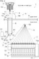
- the yarn attaching robot (yarn attaching device) 2 shown in FIG. 2 is provided to be shared by multiple spinning and winding units 1.
- the yarn attaching robot 2 can travel along a rail, not shown, between the multiple spinning and winding units 1 according to a control command from the centralized control device 101.
- upstream and downstream mean upstream and downstream in a direction in which the generated yarn Y runs during winding of it.
- the left-right direction means a direction in which the plurality of spinning and winding units 1 are lined up.
- the direction perpendicular to both the left-right direction and the up-down direction is referred to as "front-back direction”.
- Each of the spinning and winding units 1 includes a spinning device 3, a spinning take-up device 4, and a spinning and winding unit controller 102.
- the spinning and winding unit controller 102 controls operation of actuators including a motor or the like that drive various devices provided by the spinning and winding unit 1 according to a control command from the centralized control device 101.
- the spinning take-up device 4 is located downstream of the spinning device 3.
- the spinning take-up device 4 mainly includes a yarn lowering device 5, a take-up part 6, and a winding device 7.
- the yarn lowering device 5 is used for yarn lowering work which will be described later.
- the take-up part 6 performs a process of sending the yarn Y from the spinning device 3 to the winding device 7 along an appropriate path.
- the winding device 7 performs a process of winding the yarn Y to form the package P.
- the yarn processing device of the present invention mainly includes the take-up part 6 and the winding device 7.
- the spinning take-up device 4 includes, for example, lubricant guides 11 and a yarn holding device 14, in addition to the take-up part 6 and the winding device 7 as the yarn processing device. Details of the lubricant guide 11 and the yarn holding device 14 will be described later.
- a building in which the spinning and winding system 100 is installed is separated into an upper level (second floor space) and a lower level (first floor space) by a partition floor 9.
- the upper level has a second height that is higher than the first height of the lower level.
- the spinning device 3 is installed on the upper level.
- the yarn lowering device 5, which is part of the spinning take-up device 4, is installed on the upper level.
- the take-up part 6 and the winding device 7, which are part of the spinning take-up device 4, are installed on the lower level.
- Yarn passage holes 9a are formed at the partition floor 9. Each of the yarn passage holes 9a is provided for each spinning and winding unit 1. A plurality of pieces of yarn Y spun by the spinning device 3 can pass through the yarn passage hole 9a.
- the yarn passage holes 9a constitute a passage for sending the plurality of pieces of yarn Y to the lower level.
- An inter-floor tube 8 formed in a duct-like shape is fixed to the partition floor 9 to connect to the yarn passage hole 9a.
- the inter-floor tube 8 prevents yarn sway caused by wind or other external factors in the process of multiple pieces of yarn Y running from the upper level to the lower level.
- the yarn holding device 14 is provided near the yarn passage hole 9a formed at the partition floor 9.
- the yarn holding device 14 includes a yarn suction device 14a and a cutter (not shown).
- the yarn holding device 14 cuts the plurality of pieces of yarn Y running downstream from the spinning device 3 by the cutter.
- the yarn holding device 14 temporarily holds an upstream side (the spinning device 3 side) of the plurality of pieces of yarn Y which are cut, by sucking them with the yarn suction device 14a.
- the plurality of pieces of yarn Y spun by the spinning device 3 are sucked into the yarn suction device 14a of the yarn holding device 14 and are held without running to the take-up part 6 and the winding device 7.
- the yarn holding device 14 continues to hold the yarn until the abnormality is resolved.
- the spinning device 3 includes a plurality (for example, 12) of spinning ports, not shown. Molten polymer in a hot state is supplied to the spinning ports by a polymer supply device (not shown) including a gear pump or the like. The spinning device 3 continuously extrudes the molten polymer from each of the spinning ports. As a result, the yarn Y is spun continuously from the respective spinning port of the spinning device 3.
- the number of spinning ports (in other words, the number of pieces of yarn Y spun in the spinning device 3) is not limited to 12.
- a cooling device 10 and the lubricant guides 11 are installed.
- the cooling device 10 is located immediately below the spinning device 3.
- the cooling device 10 includes a plurality of cooling cylinders, not shown. Cooling air is supplied to each of the cooling cylinders through cooling air pipes that are not shown. Yarn Y passing through the cooling cylinders is cooled by the cooling air and solidified.
- the lubricant guides 11 is located below the cooling device 10.
- the lubricant guides 11 are installed in the same number as the number of pieces of yarn Y spun in the spinning device 3.
- Each of the plurality of lubricant guides 11 applies lubricant to each of the pieces of yarn Y passing through.
- the plurality of pieces of yarn Y to which the lubricant is applied pass through the yarn passage hole 9a formed in the partition floor 9 to the lower level.
- the yarn lowering device 5 is used, in yarn attaching operation, to lower the plurality of pieces of yarn Y from the upper level to the lower level where the winding device 7 and other devices are installed.
- the yarn attaching operation refers to a process of attaching the yarn Y from the spinning device 3 to the bobbin B of the winding device 7 after setting the yarn along a predetermined path. This yarn attaching operation makes the spinning take-up device 4 ready to wind the yarn Y to form the package P.
- the yarn lowering device 5 mainly includes, as shown in FIG. 3 , a main body 50, a guide member 51, an elevator 52, and a yarn sucker (yarn suction device) 53.
- the yarn lowering device 5 may be configured to include a cart that can travel between a plurality of spinning and winding units 1.
- a guide rail (not shown) extending along the direction in which the plurality of spinning and winding units 1 are lined up (along the left-right direction) is provided on the upper level, and the cart can travel along this guide rail.
- the main body 50 carries the various components of the yarn lowering device 5.
- the guide member 51 is used to guide the elevator 52 in the up-down direction when the elevator 52 is raised or lowered.
- the guide member 51 is made of, for example, a chain member in which many elemental parts are arranged in a row and each rotatably connected to the other.
- the guide member 51 When yarn lowering work is not being performed, the guide member 51 is stored in the main body 50 in a wound-up state. When yarn lowering work is being performed, the guide member 51 passes through the yarn passage hole 9a formed in the partition floor 9 and is positioned so that it extends in the up-down direction across the upper level and the lower level.
- the guide member 51 is not limited to the above configuration as long as it can guide the elevator 52 in the up-down direction.
- the guide member 51 may be made of an elongated member extending in the up-down direction.
- the elevator 52 is attached so that it can be raised and lowered in the up-down direction along the guide member 51.
- the elevator 52 includes a support 54 and a holder 55.
- the support 54 is formed in a shape of an elongated plate and is installed so as to extend in the up-down direction.
- the holder 55 is attached to the lower end of the support 54.
- An elevation motor 59 is provided in the main body 50 for elevating the elevator 52.
- the elevation motor 59 operates according to a control command from the centralized control device 101 of the spinning and winding system 100 shown in FIG. 7 .
- the holder 55 includes two yarn holding rollers 55a, 55b.
- the yarn holding rollers 55a, 55b are arranged side by side in the left-right direction of the spinning and winding system 100.
- Each of the yarn holding rollers 55a, 55b is supported by the support 54 so that it can rotate.
- Each of the axes of the yarn holding rollers 55a, 55b is arranged to extend in the front-back direction.
- the two yarn holding rollers 55a, 55b are located on both sides of the support 54 in the left-right direction with the support 54 between them.
- a ring-shaped groove formed in a substantial V-shape in cross-section is formed at an outer circumference of each of the yarn holding rollers 55a, 55b.
- the two yarn holding rollers 55a, 55b are lowered from above against the portion of the yarn Y guided in a substantially horizontal manner, causing the yarn Y to enter the groove.
- the pieces of yarn Y held by the two yarn holding rollers 55a, 55b can be converged accordingly by guiding of the V-shaped groove.
- first yarn holding roller 55a the yarn holding roller located upstream in the running direction of the yarn Y
- second yarn holding roller 55b the yarn holding roller located downstream
- the yarn sucker 53 is used to temporarily suck and hold a plurality of pieces of yarn Y spun from the spinning device 3 during the yarn lowering work.
- the yarn sucker 53 is detachably attached to the main body 50.
- the yarn sucker 53 includes, for example, a suction gun.
- the plurality of pieces of yarn Y suctioned by the yarn sucker 53 are disposed into a waste yarn box or the like which is not shown, via a suction hose (not shown) connected to the yarn sucker 53.
- the elevator 52 is moved from a standby position in the upper level to a delivery position in the lower level, by driving the elevation motor 59.
- This allows the portions of the plurality of pieces of yarn Y between the two yarn holding rollers 55a, 55b to be moved downward.
- the running path of the yarn Y extends downward from the spinning device 3, and bends substantially perpendicularly at the portion of the first yarn holding roller 55a, and then extends horizontally toward the second yarn holding roller 55b.
- the running path of the yarn Y then bends substantially perpendicularly at the portion of the second yarn holding roller 55b, and extends upward.
- the running path of the yarn Y eventually reaches the yarn sucker 53 and terminates.
- a yarn regulation guide 12 is installed upstream of the take-up part 6.
- the yarn regulation guide 12 can be, for example, a comb-shaped member at which 12 guide grooves according to the number of yarn Y are formed.
- the yarn regulation guide 12 is located on the lower level and near the take-up part 6.
- the yarn regulation guide 12 is movable in a direction parallel to the direction in which the plurality of spinning and winding units 1 are lined up.
- the yarn regulation guide 12 is driven by a guide actuator (not shown) including, for example, a cylinder.
- the take-up part 6 takes up a plurality of pieces of yarn Y running downward from the upper level and guides them to the winding device 7.
- the take-up part 6 includes a take-up frame 60 and two godet rollers 61, 62.
- the godet roller located upstream in the direction in which the yarn Y runs is referred to as upstream godet roller 61
- the godet roller located downstream is referred to as downstream godet roller 62.
- the yarn regulation guide 12 is substantially positioned directly above the upstream godet roller 61. In the following description, this position is referred to as "operating position".
- the yarn regulation guide 12 is positioned in a position that is displaced in the left-right direction from a position directly above the upstream godet roller 61. This makes the yarn attaching operation easy.
- the position of the yarn regulation guide 12 during the yarn attaching operation will be referred to as "preparing position”.
- the upstream godet roller 61 is positioned on the take-up frame 60 so that it is located almost directly below the operating position of the yarn regulation guide 12.
- the upstream godet roller 61 is driven by an upstream godet motor 61a.
- the downstream godet roller 62 can move, as shown by a chain line arrow in FIG. 2 , between a yarn attaching position close to the upstream godet roller 61 and a package forming position directly above the winding device 7.
- the downstream godet roller 62 is driven by a downstream godet motor 62a.
- the upstream godet motor 61a and the downstream godet motor 62a operate according to a control command from the spinning and winding unit controller 102.
- downstream godet roller 62 is lowered to the yarn attaching position near the upstream godet roller 61.
- the downstream godet roller 62 rises to the package forming position.
- the winding device 7 winds the plurality of pieces of yarn Y running from the take-up part 6 to form the packages P.
- the winding device 7 mainly includes a turret 71, two bobbin holders 72, a traverse device 73, and a contact roller 74.
- the turret 71 is installed so that it can rotate.
- Each of the two bobbin holders 72 is rotatably supported by the turret 71.
- the two bobbin holders 72 are positioned on opposite sides of each other across an axis of rotation of the turret 71. As the turret 71 rotates, the positions of the two bobbin holders 72 are swapped.
- one of the two bobbin holders 72 is at the winding position on the upper side and the other is at the lower standby position on the lower side, respectively.
- the bobbin holder 72 at the winding position is close proximity to the contact roller 74, while the bobbin holder 72 at the standby position is away from the contact roller 74.
- a plurality of bobbins B are mounted on each of the bobbin holders 72.
- the plurality of bobbins B are lined up in the longitudinal direction of the bobbin holder 72.
- the traverse device 73 includes a plurality of traverse guides 73a corresponding to the plurality of bobbins B. Each traverse guide 73a is arranged to correspond to each bobbin B.
- the traverse guides 73a are driven by a traverse motor 73b, which operates according to a control command of the spinning and winding unit controller 102. As each of the traverse guides 73a reciprocate in a direction parallel to the longitudinal direction of the bobbin holder 72, the pieces of yarn Y are wound onto the bobbins B while being traversed.
- the contact roller 74 contacts the outer circumferences of the plurality of packages P formed on the respective bobbins B and applies a contact pressure to each of the plurality of packages P.
- the contact roller 74 is driven by a winding motor 70, which is operated according to a control command of the spinning and winding unit controller 102.
- the yarn attaching robot 2 is located on the lower level of the building, as shown in FIG. 2 .
- the number of yarn attaching robots 2 is arbitrary, but preferably is less than the number of spinning and winding units 1.
- the yarn attaching robot 2 is capable of traveling between the plurality of spinning and winding units 1 and automatically performs the yarn attaching operation on each spinning and winding unit 1.
- the yarn attaching robot 2 mainly includes a robot main body 21, a robot arm 22, and a yarn attaching member (yarn catcher) 23.
- the operation of each part of the yarn attaching robot 2 is controlled by the robot controller (control device) 20 shown in FIG. 7 .
- the robot controller 20 mounted on the robot main body 21 is a known computer including a CPU, a ROM, a RAM, and the like.
- the robot controller 20 is connected to the centralized control device 101 by wired or wireless communication.
- a guide rail is provided on the lower level.
- the guide rail extends along the direction in which the plurality of spinning and winding units 1 are lined up (along the left-right direction).
- the robot main body 21 includes a traveling motor 21a. By driving the traveling motor 21a, the robot main body 21 can travel along the guide rail between the plurality of spinning and winding units 1.
- the robot arm 22 is configured as an articulated type and is attached to the robot main body 21.
- the robot arm 22 is driven by an arm drive motor (actuator) 22a and can perform three-dimensional movements.
- the yarn attaching member 23 is mounted to the tip of the robot arm 22.
- the operation of the traveling motor 21a and the arm drive motor 22a is controlled by the robot controller 20, as shown in FIG. 7 . That is, the traveling of the robot main body 21 and the movement of the robot arm 22 is controlled by the robot controller 20.
- the yarn attaching member 23 is formed in a shape that makes hooking a plurality of pieces of yarn Y easy.
- the yarn attaching member 23 can, for example, be formed in the shape of a hook.
- the yarn attaching member 23 hooks and restrains the plurality of pieces of yarn Y. As the yarn attaching member 23 moves, it can guide the plurality of pieces of yarn Y hooked on it.
- FIGS. 4 to 6 show a situation where the yarn attaching robot 2 receives the yarn Y from the yarn lowering device 5.
- the spinning and winding unit 1 for example in the case of a preparation stage before starting the forming of the package P, in the case of a yarn breakage for some reason, or the like, it is necessary to perform the yarn attaching operation to attach the plurality of pieces of yarn Y spun from the spinning device 3 to the take-up part 6 and the like before starting (restarting) winding of yarn Y by the winding device 7.
- the yarn lowering work that the plurality of pieces of yarn Y are lowered from the spinning device 3 from the upper level to the lower level is performed by the yarn lowering device 5 and an operator's operation.
- the yarn attaching operation at the lower level is automatically performed by the yarn attaching robot 2.
- the operator moves the yarn lowering device 5 to the target spinning and winding unit 1.
- the operator then removes the yarn sucker 53 from the yarn lowering device 5, and at the same time or before that, makes the yarn sucker 53 put into operation.
- the operator uses the yarn sucker 53 to suck and hold a plurality of pieces of yarn Y spun from the spinning device 3 upstream from the lubricant guides 11.
- the operator then attaches the plurality of pieces of yarn Y suctioned and held by the yarn sucker 53 to the lubricant guides 11. After attaching the plurality of pieces of yarn Y on the lubricant guides 11, or after the yarn lowering device 5 has moved to the target spinning and winding unit 1, the operator makes the guide member 51 of the yarn lowering device 5 span across the two levels through the yarn passage hole 9a at appropriate timing.
- the operator then takes yarn attaching tool (not shown) in a hook shape for example, from an appropriate place and, between the yarn sucker 53 and the lubricant guides 11, catches the yarn Y sucked and held by the yarn sucker 53 on the yarn attaching tool. After the plurality of pieces of the yarn Y are caught on the yarn attaching tool, the operator moves the yarn attaching tool so that the plurality of pieces of yarn Y between the yarn sucker 53 and the yarn attaching tool are positioned directly under the two yarn holding rollers 55a, 55b provided by the holder 55 of the yarn lowering device 5.
- the operator operates an operation switch or the like which is not shown, to instruct the yarn lowering device 5 to start the yarn lowering operation.
- the elevator 52 of the yarn lowering device 5 moves along the guide member 51 to the delivery position of the lower level.
- the plurality of pieces of yarn Y that are held on the two yarn holding rollers 55a, 55b move to the lower position.
- the intermediate portions of the plurality of pieces of yarn Y held by the yarn sucker 53 are transported by the yarn lowering device 5 to the vicinity of the yarn regulation guide 12.
- the yarn attaching robot 2 moves to the target spinning and winding unit 1 according to the operation command of the centralized control device 101.
- the yarn attaching robot 2 makes the robot arm 22 operate.
- the yarn attaching member 23 at the tip of the robot arm 22 comes into close proximity to the plurality of pieces of yarn Y that are attached to the yarn holding rollers 55a, 55b of the yarn lowering device 5.
- the yarn attaching robot 2 hooks a bundle of the plurality of pieces of yarn Y converged by the second yarn holding roller 55b onto the yarn attaching member 23.
- the location where the yarn Y is hooked is near the second yarn holding roller 55b. In this way, the yarn attaching robot 2 receives the yarn Y from the yarn lowering device 5.
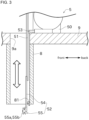
- a yarn guide (yarn path changing member) 81 is installed at the outlet for the yarn Y located at the lower side of the inter-floor tube 8, and on the side near the second yarn holding roller 55b, as shown in FIG. 5 , etc.
- the yarn guide 81 is made of, for example, a hook-shaped member. However, it is not limited to this.
- the yarn guide 81 can be installed at any position on the underside of the inter-floor tube 8, and the yarn guide 81 can also include, for example, a roller.
- the yarn guide 81 is used by the yarn attaching robot 2 to regulate the yarn Y between the yarn sucker 53 and the yarn attaching member 23 after the yarn attaching robot 2 has captured the yarn Y with the yarn attaching member 23.
- the yarn guide 81 regulates the path of the portion in the inter-floor tube 8 in the yarn Y between the yarn sucker 53 and the yarn attaching member 23, thereby changing the yarn path.
- the yarn guide 81 can be configured to regulate the yarn Y between the lubricant guides 11 and the yarn attaching member 23, inside the inter-floor tube 8.
- the yarn attaching robot 2 attaches the plurality of pieces of yarn Y hooked by the yarn attaching member 23 on the yarn guide 81 as shown in FIG. 5 . After hanging the yarn Y on the yarn guide 81, the yarn attaching robot 2 moves the yarn attaching member 23 so as to remove the yarn Y from the two yarn holding rollers 55a, 55b. The yarn attaching robot 2 then pulls the yarn Y out of an opening at the bottom end of the inter-floor tube 8, as shown in FIG. 6 .
- the yarn attaching robot 2 moves the robot arm 22 so that the yarn Y is attached to the yarn regulation guide 12, the take-up part 6 (the upstream godet roller 61 and the downstream godet roller 62), and the plurality of fulcrum guides 13, in that order.
- the yarn attaching robot 2 then moves the robot arm 22 so that the yarn attaching member 23 is positioned at a predetermined position which is below the upper bobbin holder 72, and each of the plurality of pieces of yarn Y is brought into contact with the respective bobbin B.
- the winding device 7 begins its winding operation.
- the traverse guides 73a reciprocate in the direction parallel to an axial direction of the bobbin B in conjunction with the rotation of the bobbin B.
- the yarn Y is hooked on each of the traverse guides 73a.
- each of the pieces of the yarn Y can be wound onto the bobbin B while being traversed by the traverse guide 73a.
- the packages P can be formed.
- the yarn attaching robot 2 After securing the plurality of pieces of yarn Y to the plurality of bobbins B, the yarn attaching robot 2 cuts the yarn Y between the yarn sucker 53 and the bobbin B at a point close to the bobbin B by means of a cutter which is not shown. The plurality of pieces of yarn Y between the cut point and the yarn sucker 53 are sucked by the yarn sucker 53 and discarded to the waste yarn box. The plurality of pieces of yarn Y spun by the spinning device 3 are then wound onto the bobbins B to form the packages P.
- the spinning of the spinning device 3 does not stop, so that the yarn Y is continuously supplied from the upstream side. Since the yarn sucker 53 in the yarn lowering device 5 sucks the yarn Y, the yarn attaching robot 2 of this embodiment can keep the yarn Y captured by the yarn attaching member 23 of the robot arm 22 from becoming slack without providing a suction port on the robot arm 22 that uses negative pressure. Therefore, the weight that the robot arm 22 must support is reduced because a flexible negative pressure piping does not need to be attached to the robot arm 22. As a result, the configuration of the robot arm 22 can be simplified and the cost can be reduced. Since no air noise is generated at the tip of the robot arm 22, the noise during yarn attaching operation can be reduced well at the lower level.
- the yarn attaching robot 2 of this embodiment is used for the spinning and winding unit 1.
- the spinning and winding unit 1 includes the spinning device 3, the take-up part 6 and the winding device 7, and the yarn sucker 53.
- the spinning device 3 spins the yarn Y continuously.
- Each of the take-up part 6 and the winding device 7 takes up or winds the yarn Y continuously spun from the spinning device 3.
- the yarn sucker 53 is used to temporarily suck and receive the yarn being continuously spun from the spinning device 3.
- the yarn attaching robot 2 includes the yarn attaching member 23, the arm drive motor 22a, and the robot controller 20.
- the yarn attaching member 23 is used to catch the yarn Y.
- the arm drive motor 22a moves the yarn attaching member 23.
- the robot controller 20 controls the operation of the arm drive motor 22a.
- the yarn attaching member 23 catches the yarn Y that has been spun from the spinning device 3 and is being sucked into the yarn sucker 53.
- the robot controller 20 controls the operation of the arm drive motor 22a so that the yarn Y is attached to the take-up part 6 and the winding device 7 by the yarn attaching member 23 in the state where the yarn Y is being sucked into the yarn sucker 53 provided by the spinning and winding unit 1.
- the yarn guide 81 is provided in the spinning and winding unit 1 provided by the spinning and winding system 100.
- the yarn guide 81 contacts the yarn portion between the yarn attaching member 23 and the yarn sucker 53, to change the yarn path of the yarn portion, during the operation in which the yarn attaching member 23 is driven by the arm drive motor 22a to attach the yarn to the take-up part 6 and the winding device 7.
- the take-up part 6 and the winding device 7 are provided on the lower level at the first height level.
- the spinning device 3 and the yarn sucker 53 are provided on the upper level at the second height level higher than the first height level.
- the spinning and winding system 100 includes the yarn lowering device 5.
- the yarn lowering device 5 lowers the intermediate point of the yarn Y being spun from the spinning device 3 and being sucked into the yarn sucker 53, from the upper level to the lower level.
- the spinning and winding system 100 of this embodiment includes the spinning and winding unit 1 and the yarn attaching robot 2.
- the spinning and winding unit 1 includes the spinning device 3, the take-up part 6 and the winding device 7, and the yarn sucker 53.
- the spinning device 3 spins the yarn Y continuously.
- Each of the take-up part 6 and the winding device 7 takes up or winds the yarn Y continuously spun from the spinning device 3.
- the yarn sucker 53 is used to temporarily suck and receive the yarn being continuously spun from the spinning device 3.
- the yarn attaching robot 2 includes the yarn attaching member 23, the arm drive motor 22a, and the robot controller 20.
- the yarn attaching member 23 catches the yarn Y.
- the arm drive motor 22a moves the yarn attaching member 23.
- the robot controller 20 controls the operation of the arm drive motor 22a.
- the yarn attaching member 23 catches the yarn Y that has been spun from the spinning device 3 and is being sucked into the yarn sucker 53.
- the robot controller 20 controls the operation of the arm drive motor 22a so that the yarn Y is attached to the take-up part 6 by the yarn attaching member 23 in the state where the yarn Y is being sucked into the yarn sucker 53 provided by the spinning and winding unit 1.
- the spinning and winding system 100 includes the yarn guide 81.
- the yarn guide 81 contacts the yarn portion between the yarn attaching member 23 and the yarn sucker 53 to change the yarn path of the yarn portion, during the operation in which the yarn attaching member 23 is driven by the arm drive motor 22a to attach the yarn Y to the take-up part 6 and the winding device 7.
- the take-up part 6 and the winding device 7 are provided on the lower level at the first height level.
- the spinning device 3 and the yarn sucker 53 are provided on the upper level at the second height level higher than the first height level.
- the spinning and winding system 100 includes the yarn lowering device 5.
- the yarn lowering device 5 lowers the intermediate point of the yarn Y being spun from the spinning device 3 and being sucked into the yarn sucker 53, from the upper level to the lower level.
- the spinning and winding system 100 of this embodiment includes a plurality of spinning and winding units 1.
- the guide rail is provided in the lower level.
- the yarn attaching robot 2 moves between the plurality of spinning and winding units 1 along the guide rail.
- the number of the yarn attaching robots 2 is less than the number of the spinning and winding units 1.
- the plurality of pieces of yarn Y may be sucked and held by the yarn suction device 14a of the yarn holding device 14.
- the guide member 51 guiding the elevator 52 may be installed in each of the spinning and winding units 1.
- the yarn Y between the second yarn holding roller 55b and the first yarn holding roller 55a can be hooked by the yarn attaching member 23.
- the yarn guide 81 can be omitted and the second yarn holding roller 55b can be configured to perform the yarn regulation function that the yarn guide 81 had.
- the yarn Y immediately upstream from the first yarn holding roller 55a can also be hooked by the yarn attaching member 23.
- the cutting of the yarn Y when the yarn attaching operation is completed may be performed by a cutter provided by the yarn lowering device 5 or by a cutter provided by the yarn holding device 14.
- the yarn attaching robot 2 of the above embodiment may also be applied when the winding operation of the yarn Y is temporarily stopped and a plurality of pieces of yarn Y are suctioned and held by an aspirator installed near the yarn regulation guide 12, and the yarn attaching operation is performed by receiving the yarn Y from the aspirator or yarn regulation guide 12.
- the aspirator corresponds to a yarn suction device.
Landscapes
- Engineering & Computer Science (AREA)
- Mechanical Engineering (AREA)
- Textile Engineering (AREA)
- Spinning Methods And Devices For Manufacturing Artificial Fibers (AREA)
Abstract
Description
- The present invention relates to a yarn attaching device and, spinning and processing equipment including the yarn attaching device.
- Conventional spinning and processing equipment for producing synthetic fibers is known.
PTL 1 discloses a yarn attaching method for guiding a spun yarn to a take-up roller in this type of spinning and processing equipment.PTL 2 discloses a melt spinning device, which is this type of spinning and processing equipment. - In the yarn attaching method of
PTL 1, yarn that is being wound onto a waste roll is wound onto a supply roller or the like by means of a yarn attaching tool held by an operator's hand. - The melt spinning device of
PTL 2 includes an automatic operation device. The automatic operation device guides a group of yarn to a godet unit and a winding unit for attaching and insertion of the yarn, while holding the group by means of a suction injector provided at an end of a robot arm. -
- PTL 1:
Japanese Unexamined Patent Publication No. S50(1975)-138116 - PTL 2:
Japanese Unexamined Patent Publication (Translation of PCT Application) No. 2020-526675 - To reduce the burden on the operator and improve production efficiency, the manual work of the operator as in
PTL 1 has been replaced by the operation of the robot such as disclosed inPTL 2. However, in the melt spinning device ofPTL 2, it is necessary for the robot arm to support the weight of the suction injector for holding a group of the yarn and the compressed air pipeline that supplies compressed air, etc., making it difficult to downsize the device. - The present invention was made in view of the above circumstances, and its purpose is to provide a compact yarn attaching device.
- The problem to be solved by the present invention is as described above, and next, means for solving the problem and effects thereof will be described.
- According to the first aspect of the present invention, a yarn attaching device with the following configuration is provided. That is, the yarn attaching device is used for a spinning and winding unit. The spinning and winding unit includes a spinning device, a yarn processing device, and a yarn suction device. The spinning device spins yarn continuously. The yarn processing device takes up or winds the yarn continuously spun from the spinning device. The yarn suction device is used to temporarily suck and receive the yarn being continuously spun from the spinning device. The yarn attaching device includes a yarn catcher, an actuator, and a controller. The yarn catcher is used to catch the yarn. The actuator moves the yarn catcher. The controller controls operation of the actuator. The yarn catcher catches the yarn that has been spun from the spinning device and is being sucked into the yarn suction device. The controller controls the operation of the actuator so that the yarn is attached to the yarn processing device by the yarn catcher in a state where the yarn is being sucked into the yarn suction device provided by the spinning and winding unit.
- This eliminates the need to mount a suction device such as a suction gun, which is heavy, on the yarn attaching device, thereby achieving a smaller size and lower power output of the yarn attaching device.
- It is preferable that the yarn attaching device is configured as follows. That is, the spinning and winding unit includes a yarn path changing member. The yarn path changing member contacts a yarn portion between the yarn catcher and the yarn suction device or between the spinning device and the yarn catcher to change a yarn path of the yarn portion, during operation in which the yarn catcher is driven by the actuator to attach the yarn to the yarn processing device.
- This makes yarn attaching operation to the yarn processing device easy.
- In the yarn attaching device described above, it is preferable to have the following configuration. That is, the yarn processing device is provided in a first floor space at a first height level. The spinning device and the yarn suction device are provided in a second floor space at a second height level higher than the first height level. The spinning and winding unit includes a yarn lowering device which lowers an intermediate point of the yarn being spun from the spinning device and being sucked into the yarn suction device, from the second floor space to the first floor space.
- This reduces noise in the first floor space.
- According to the second aspect of the present invention, spinning and processing equipment with the following configuration is provided. That is, this spinning and processing equipment includes a spinning and winding unit and a yarn attaching device. The spinning and winding unit includes a spinning device, a yarn processing device, and a yarn suction device. The spinning device spins yarn continuously. The yarn processing device takes up or winds the yarn continuously spun from the spinning device. The yarn suction device is used to temporarily suck and receive the yarn being continuously spun from the spinning device. The yarn attaching device includes a yarn catcher, an actuator, and a controller. The yarn catcher is used to catch the yarn. The actuator moves the yarn catcher. The controller controls operation of the actuator. The yarn catcher catches the yarn that has been spun from the spinning device and is being sucked into the yarn suction device. The controller controls the operation of the actuator so that the yarn is attached to the yarn processing device by the yarn catcher in a state where the yarn is being sucked into the yarn suction device provided by the spinning and winding unit.
- This simplifies the spinning and processing equipment.
- It is preferable that the spinning and processing equipment is configured as follows. That is, the spinning and processing equipment includes a yarn path changing member. The yarn path changing member contacts a yarn portion between the yarn catcher and the yarn suction device or between the spinning device and the yarn catcher to change a yarn path of the yarn portion, during operation in which the yarn catcher is driven by the actuator to attach the yarn to the yarn processing device.
- This makes yarn attaching operation to the yarn processing device easy.
- It is preferable that the spinning and processing equipment is configured as follows. That is, the yarn processing device is provided in a first floor space at a first height level. The spinning device and yarn suction device are provided in a second floor space at a second height level higher than the first height level. The spinning and processing equipment includes a yarn lowering device which lowers an intermediate point of the yarn being spun from the spinning device and being sucked into the yarn suction device, from the second floor space to the first floor space.
- This reduces noise in the first floor space.
- It is preferable that the spinning and processing equipment is configured as follows. That is, the spinning and processing equipment includes a plurality of spinning and winding units. A guide rail is provided in the first floor space. The yarn attaching device moves between the plurality of spinning and winding units along the guide rail.
- This allows the yarn attaching device to move between the plurality of spinning and winding units so that the yarn attaching device can operate efficiently.
- In the spinning and processing equipment described above, it is preferred that a number of yarn attaching devices is less than a number of spinning and winding units.
- This allows the yarn attaching devices to be operated efficiently.
-
-
FIG. 1 is a diagonal view showing a schematic configuration of a spinning and winding system according to one embodiment of the present invention. -
FIG. 2 is a schematic view showing a configuration of a spinning and winding unit. -
FIG. 3 is a schematic view showing a configuration of a yarn lowering device. -
FIG. 4 is a partial diagonal view showing a situation where a yarn attaching robot receives yarn from a yarn lowering device. -
FIG. 5 is a view showing a situation where the yarn is attached to a yarn guide by the yarn attaching robot. -
FIG. 6 is a view showing a situation where the yarn attaching robot pulls out the yarn from the yarn lowering device. -
FIG. 7 is a block diagram briefly showing a control structure of the spinning and winding system. - Next, embodiments of the present invention will be described with reference to the drawings.
- A spinning and winding system (spinning and processing equipment) 100 shown in
FIG. 1 is a system for generating synthetic fiber yarn Y and winding it to form a package P. In the spinning and windingsystem 100, the yarn Y of synthetic fibers is produced by extruding molten synthetic fiber material. The spinning and windingsystem 100 is installed in a building having multiple levels in the plant. - The spinning and winding
system 100 has a plurality of spinning and windingunits 1, as shown inFIG. 1 . The plurality of spinning and windingunits 1 are lined up in a left-right direction. Each spinning and windingunit 1 produces yarn Y of synthetic fiber and a package P. The spinning and windingsystem 100 includes acentralized control device 101 for controlling the entire system. As shown inFIG. 7 , thecentralized control device 101 controls operation of each spinning and windingunit 1, ayarn attaching robot 2 which will be described later, and the like, included in the spinning and windingsystem 100. - The yarn attaching robot (yarn attaching device) 2 shown in
FIG. 2 is provided to be shared by multiple spinning and windingunits 1. Theyarn attaching robot 2 can travel along a rail, not shown, between the multiple spinning and windingunits 1 according to a control command from thecentralized control device 101. - Hereinafter, "upstream" and "downstream" mean upstream and downstream in a direction in which the generated yarn Y runs during winding of it. The left-right direction means a direction in which the plurality of spinning and winding
units 1 are lined up. The direction perpendicular to both the left-right direction and the up-down direction is referred to as "front-back direction". - Each of the spinning and winding
units 1 includes aspinning device 3, a spinning take-updevice 4, and a spinning and windingunit controller 102. The spinning and windingunit controller 102 controls operation of actuators including a motor or the like that drive various devices provided by the spinning and windingunit 1 according to a control command from thecentralized control device 101. The spinning take-updevice 4 is located downstream of thespinning device 3. The spinning take-updevice 4 mainly includes ayarn lowering device 5, a take-uppart 6, and a windingdevice 7. Theyarn lowering device 5 is used for yarn lowering work which will be described later. The take-uppart 6 performs a process of sending the yarn Y from thespinning device 3 to the windingdevice 7 along an appropriate path. The windingdevice 7 performs a process of winding the yarn Y to form the package P. The yarn processing device of the present invention mainly includes the take-uppart 6 and the windingdevice 7. - The spinning take-up
device 4 includes, for example, lubricant guides 11 and ayarn holding device 14, in addition to the take-uppart 6 and the windingdevice 7 as the yarn processing device. Details of thelubricant guide 11 and theyarn holding device 14 will be described later. - A building in which the spinning and winding
system 100 is installed is separated into an upper level (second floor space) and a lower level (first floor space) by apartition floor 9. The upper level has a second height that is higher than the first height of the lower level. Thespinning device 3 is installed on the upper level. Theyarn lowering device 5, which is part of the spinning take-updevice 4, is installed on the upper level. The take-uppart 6 and the windingdevice 7, which are part of the spinning take-updevice 4, are installed on the lower level. - Yarn passage holes 9a are formed at the
partition floor 9. Each of theyarn passage holes 9a is provided for each spinning and windingunit 1. A plurality of pieces of yarn Y spun by thespinning device 3 can pass through theyarn passage hole 9a. Theyarn passage holes 9a constitute a passage for sending the plurality of pieces of yarn Y to the lower level. - An
inter-floor tube 8 formed in a duct-like shape is fixed to thepartition floor 9 to connect to theyarn passage hole 9a. Theinter-floor tube 8 prevents yarn sway caused by wind or other external factors in the process of multiple pieces of yarn Y running from the upper level to the lower level. - On the upper level, the
yarn holding device 14 is provided near theyarn passage hole 9a formed at thepartition floor 9. Theyarn holding device 14 includes ayarn suction device 14a and a cutter (not shown). When some abnormality occurs in yarn Y or each device in part of the spinning take-up device 4 (for example, the take-uppart 6 or the winding device 7) or the like in a downstream side, theyarn holding device 14 cuts the plurality of pieces of yarn Y running downstream from thespinning device 3 by the cutter. Furthermore, theyarn holding device 14 temporarily holds an upstream side (thespinning device 3 side) of the plurality of pieces of yarn Y which are cut, by sucking them with theyarn suction device 14a. Thus, the plurality of pieces of yarn Y spun by thespinning device 3 are sucked into theyarn suction device 14a of theyarn holding device 14 and are held without running to the take-uppart 6 and the windingdevice 7. Theyarn holding device 14 continues to hold the yarn until the abnormality is resolved. - The
spinning device 3 includes a plurality (for example, 12) of spinning ports, not shown. Molten polymer in a hot state is supplied to the spinning ports by a polymer supply device (not shown) including a gear pump or the like. Thespinning device 3 continuously extrudes the molten polymer from each of the spinning ports. As a result, the yarn Y is spun continuously from the respective spinning port of thespinning device 3. The number of spinning ports (in other words, the number of pieces of yarn Y spun in the spinning device 3) is not limited to 12. - In the upper level of the spinning and winding
system 100, acooling device 10 and the lubricant guides 11 are installed. - The
cooling device 10 is located immediately below thespinning device 3. Thecooling device 10 includes a plurality of cooling cylinders, not shown. Cooling air is supplied to each of the cooling cylinders through cooling air pipes that are not shown. Yarn Y passing through the cooling cylinders is cooled by the cooling air and solidified. - The lubricant guides 11 is located below the
cooling device 10. The lubricant guides 11 are installed in the same number as the number of pieces of yarn Y spun in thespinning device 3. Each of the plurality of lubricant guides 11 applies lubricant to each of the pieces of yarn Y passing through. The plurality of pieces of yarn Y to which the lubricant is applied pass through theyarn passage hole 9a formed in thepartition floor 9 to the lower level. - The
yarn lowering device 5 is used, in yarn attaching operation, to lower the plurality of pieces of yarn Y from the upper level to the lower level where the windingdevice 7 and other devices are installed. The yarn attaching operation refers to a process of attaching the yarn Y from thespinning device 3 to the bobbin B of the windingdevice 7 after setting the yarn along a predetermined path. This yarn attaching operation makes the spinning take-updevice 4 ready to wind the yarn Y to form the package P. - The
yarn lowering device 5 mainly includes, as shown inFIG. 3 , amain body 50, aguide member 51, anelevator 52, and a yarn sucker (yarn suction device) 53. Theyarn lowering device 5 may be configured to include a cart that can travel between a plurality of spinning and windingunits 1. For example, it can be configured so that a guide rail (not shown) extending along the direction in which the plurality of spinning and windingunits 1 are lined up (along the left-right direction) is provided on the upper level, and the cart can travel along this guide rail. - The
main body 50 carries the various components of theyarn lowering device 5. - The
guide member 51 is used to guide theelevator 52 in the up-down direction when theelevator 52 is raised or lowered. Theguide member 51 is made of, for example, a chain member in which many elemental parts are arranged in a row and each rotatably connected to the other. - When yarn lowering work is not being performed, the
guide member 51 is stored in themain body 50 in a wound-up state. When yarn lowering work is being performed, theguide member 51 passes through theyarn passage hole 9a formed in thepartition floor 9 and is positioned so that it extends in the up-down direction across the upper level and the lower level. Theguide member 51 is not limited to the above configuration as long as it can guide theelevator 52 in the up-down direction. For example, theguide member 51 may be made of an elongated member extending in the up-down direction. - The
elevator 52 is attached so that it can be raised and lowered in the up-down direction along theguide member 51. As shown inFIG. 3 , theelevator 52 includes asupport 54 and aholder 55. Thesupport 54 is formed in a shape of an elongated plate and is installed so as to extend in the up-down direction. Theholder 55 is attached to the lower end of thesupport 54. Anelevation motor 59 is provided in themain body 50 for elevating theelevator 52. Theelevation motor 59 operates according to a control command from thecentralized control device 101 of the spinning and windingsystem 100 shown inFIG. 7 . - The
holder 55 includes twoyarn holding rollers yarn holding rollers system 100. Each of theyarn holding rollers support 54 so that it can rotate. Each of the axes of theyarn holding rollers yarn holding rollers support 54 in the left-right direction with thesupport 54 between them. - A ring-shaped groove formed in a substantial V-shape in cross-section is formed at an outer circumference of each of the
yarn holding rollers yarn holding rollers yarn holding rollers - In the following description, with the plurality of pieces of yarn Y spun by the
spinning device 3 being sucked and held by theyarn sucker 53, the yarn holding roller located upstream in the running direction of the yarn Y is referred to as "firstyarn holding roller 55a" and the yarn holding roller located downstream is referred to as "secondyarn holding roller 55b". - The
yarn sucker 53 is used to temporarily suck and hold a plurality of pieces of yarn Y spun from thespinning device 3 during the yarn lowering work. Theyarn sucker 53 is detachably attached to themain body 50. Theyarn sucker 53 includes, for example, a suction gun. The plurality of pieces of yarn Y suctioned by theyarn sucker 53 are disposed into a waste yarn box or the like which is not shown, via a suction hose (not shown) connected to theyarn sucker 53. - In this configuration, with the intermediate portions of the plurality of pieces of yarn Y held on the two
yarn holding rollers elevator 52 is moved from a standby position in the upper level to a delivery position in the lower level, by driving theelevation motor 59. This allows the portions of the plurality of pieces of yarn Y between the twoyarn holding rollers spinning device 3, and bends substantially perpendicularly at the portion of the firstyarn holding roller 55a, and then extends horizontally toward the secondyarn holding roller 55b. The running path of the yarn Y then bends substantially perpendicularly at the portion of the secondyarn holding roller 55b, and extends upward. The running path of the yarn Y eventually reaches theyarn sucker 53 and terminates. - As shown in
FIG. 2 , ayarn regulation guide 12 is installed upstream of the take-uppart 6. Theyarn regulation guide 12 can be, for example, a comb-shaped member at which 12 guide grooves according to the number of yarn Y are formed. Theyarn regulation guide 12 is located on the lower level and near the take-uppart 6. Theyarn regulation guide 12 is movable in a direction parallel to the direction in which the plurality of spinning and windingunits 1 are lined up. Theyarn regulation guide 12 is driven by a guide actuator (not shown) including, for example, a cylinder. - The take-up
part 6 takes up a plurality of pieces of yarn Y running downward from the upper level and guides them to the windingdevice 7. The take-uppart 6 includes a take-up frame 60 and twogodet rollers upstream godet roller 61, and the godet roller located downstream is referred to asdownstream godet roller 62. - During winding of the yarn Y, the
yarn regulation guide 12 is substantially positioned directly above theupstream godet roller 61. In the following description, this position is referred to as "operating position". - During the yarn attaching operation, the
yarn regulation guide 12 is positioned in a position that is displaced in the left-right direction from a position directly above theupstream godet roller 61. This makes the yarn attaching operation easy. In the following description, the position of theyarn regulation guide 12 during the yarn attaching operation will be referred to as "preparing position". - The
upstream godet roller 61 is positioned on the take-up frame 60 so that it is located almost directly below the operating position of theyarn regulation guide 12. Theupstream godet roller 61 is driven by anupstream godet motor 61a. On the other hand, thedownstream godet roller 62 can move, as shown by a chain line arrow inFIG. 2 , between a yarn attaching position close to theupstream godet roller 61 and a package forming position directly above the windingdevice 7. Thedownstream godet roller 62 is driven by adownstream godet motor 62a. Theupstream godet motor 61a and thedownstream godet motor 62a operate according to a control command from the spinning and windingunit controller 102. - During the yarn attaching operation, the
downstream godet roller 62 is lowered to the yarn attaching position near theupstream godet roller 61. When the yarn attaching operation is completed, thedownstream godet roller 62 rises to the package forming position. - The winding
device 7 winds the plurality of pieces of yarn Y running from the take-uppart 6 to form the packages P. The windingdevice 7 mainly includes aturret 71, twobobbin holders 72, atraverse device 73, and acontact roller 74. - The
turret 71 is installed so that it can rotate. Each of the twobobbin holders 72 is rotatably supported by theturret 71. The twobobbin holders 72 are positioned on opposite sides of each other across an axis of rotation of theturret 71. As theturret 71 rotates, the positions of the twobobbin holders 72 are swapped. - Specifically, one of the two
bobbin holders 72 is at the winding position on the upper side and the other is at the lower standby position on the lower side, respectively. Thebobbin holder 72 at the winding position is close proximity to thecontact roller 74, while thebobbin holder 72 at the standby position is away from thecontact roller 74. A plurality of bobbins B are mounted on each of thebobbin holders 72. The plurality of bobbins B are lined up in the longitudinal direction of thebobbin holder 72. - The
traverse device 73 includes a plurality of traverse guides 73a corresponding to the plurality of bobbins B. Eachtraverse guide 73a is arranged to correspond to each bobbin B. The traverse guides 73a are driven by atraverse motor 73b, which operates according to a control command of the spinning and windingunit controller 102. As each of the traverse guides 73a reciprocate in a direction parallel to the longitudinal direction of thebobbin holder 72, the pieces of yarn Y are wound onto the bobbins B while being traversed. - The
contact roller 74 contacts the outer circumferences of the plurality of packages P formed on the respective bobbins B and applies a contact pressure to each of the plurality of packages P. Thecontact roller 74 is driven by a windingmotor 70, which is operated according to a control command of the spinning and windingunit controller 102. - The
yarn attaching robot 2 is located on the lower level of the building, as shown inFIG. 2 . The number ofyarn attaching robots 2 is arbitrary, but preferably is less than the number of spinning and windingunits 1. Theyarn attaching robot 2 is capable of traveling between the plurality of spinning and windingunits 1 and automatically performs the yarn attaching operation on each spinning and windingunit 1. - The
yarn attaching robot 2 mainly includes a robotmain body 21, arobot arm 22, and a yarn attaching member (yarn catcher) 23. The operation of each part of theyarn attaching robot 2 is controlled by the robot controller (control device) 20 shown inFIG. 7 . Therobot controller 20 mounted on the robotmain body 21 is a known computer including a CPU, a ROM, a RAM, and the like. Therobot controller 20 is connected to thecentralized control device 101 by wired or wireless communication. - A guide rail, not shown, is provided on the lower level. The guide rail extends along the direction in which the plurality of spinning and winding
units 1 are lined up (along the left-right direction). The robotmain body 21 includes a travelingmotor 21a. By driving the travelingmotor 21a, the robotmain body 21 can travel along the guide rail between the plurality of spinning and windingunits 1. - The
robot arm 22 is configured as an articulated type and is attached to the robotmain body 21. Therobot arm 22 is driven by an arm drive motor (actuator) 22a and can perform three-dimensional movements. Theyarn attaching member 23 is mounted to the tip of therobot arm 22. The operation of the travelingmotor 21a and thearm drive motor 22a is controlled by therobot controller 20, as shown inFIG. 7 . That is, the traveling of the robotmain body 21 and the movement of therobot arm 22 is controlled by therobot controller 20. - The
yarn attaching member 23 is formed in a shape that makes hooking a plurality of pieces of yarn Y easy. Theyarn attaching member 23 can, for example, be formed in the shape of a hook. Theyarn attaching member 23 hooks and restrains the plurality of pieces of yarn Y. As theyarn attaching member 23 moves, it can guide the plurality of pieces of yarn Y hooked on it. - Next, the yarn attaching operation by the
yarn attaching robot 2 will now be described with reference toFIGS. 4 to 6. FIGS. 4 to 6 show a situation where theyarn attaching robot 2 receives the yarn Y from theyarn lowering device 5. - In the spinning and winding
unit 1, for example in the case of a preparation stage before starting the forming of the package P, in the case of a yarn breakage for some reason, or the like, it is necessary to perform the yarn attaching operation to attach the plurality of pieces of yarn Y spun from thespinning device 3 to the take-uppart 6 and the like before starting (restarting) winding of yarn Y by the windingdevice 7. - In this embodiment, the yarn lowering work that the plurality of pieces of yarn Y are lowered from the
spinning device 3 from the upper level to the lower level is performed by theyarn lowering device 5 and an operator's operation. The yarn attaching operation at the lower level is automatically performed by theyarn attaching robot 2. - Before starting the yarn lowering work, the operator moves the
yarn lowering device 5 to the target spinning and windingunit 1. The operator then removes theyarn sucker 53 from theyarn lowering device 5, and at the same time or before that, makes theyarn sucker 53 put into operation. The operator uses theyarn sucker 53 to suck and hold a plurality of pieces of yarn Y spun from thespinning device 3 upstream from the lubricant guides 11. - The operator then attaches the plurality of pieces of yarn Y suctioned and held by the
yarn sucker 53 to the lubricant guides 11. After attaching the plurality of pieces of yarn Y on the lubricant guides 11, or after theyarn lowering device 5 has moved to the target spinning and windingunit 1, the operator makes theguide member 51 of theyarn lowering device 5 span across the two levels through theyarn passage hole 9a at appropriate timing. - The operator then takes yarn attaching tool (not shown) in a hook shape for example, from an appropriate place and, between the
yarn sucker 53 and the lubricant guides 11, catches the yarn Y sucked and held by theyarn sucker 53 on the yarn attaching tool. After the plurality of pieces of the yarn Y are caught on the yarn attaching tool, the operator moves the yarn attaching tool so that the plurality of pieces of yarn Y between theyarn sucker 53 and the yarn attaching tool are positioned directly under the twoyarn holding rollers holder 55 of theyarn lowering device 5. - In this state, when the operator removes the yarn attaching tool, the plurality of pieces of yarn Y (i.e., the intermediate portions of pieces of the yarn Y) between the lubricant guides 11 and the
yarn sucker 53 are caught on the twoyarn holding rollers yarn holding rollers - After the yarn lowering preparation work is completed, the operator operates an operation switch or the like which is not shown, to instruct the
yarn lowering device 5 to start the yarn lowering operation. When the yarn lowering operation is started, theelevator 52 of theyarn lowering device 5 moves along theguide member 51 to the delivery position of the lower level. As a result, the plurality of pieces of yarn Y that are held on the twoyarn holding rollers yarn sucker 53 are transported by theyarn lowering device 5 to the vicinity of theyarn regulation guide 12. - During or after the yarn attaching operation described above, the
yarn attaching robot 2 moves to the target spinning and windingunit 1 according to the operation command of thecentralized control device 101. Upon arrival at the target spinning and windingunit 1, theyarn attaching robot 2 makes therobot arm 22 operate. As a result, theyarn attaching member 23 at the tip of therobot arm 22 comes into close proximity to the plurality of pieces of yarn Y that are attached to theyarn holding rollers yarn lowering device 5. - As shown in
FIG. 5 , upstream from theyarn sucker 53 and downstream from the secondyarn holding roller 55b, theyarn attaching robot 2 hooks a bundle of the plurality of pieces of yarn Y converged by the secondyarn holding roller 55b onto theyarn attaching member 23. The location where the yarn Y is hooked is near the secondyarn holding roller 55b. In this way, theyarn attaching robot 2 receives the yarn Y from theyarn lowering device 5. - As an example in the spinning and winding
unit 1 of this embodiment, a yarn guide (yarn path changing member) 81 is installed at the outlet for the yarn Y located at the lower side of theinter-floor tube 8, and on the side near the secondyarn holding roller 55b, as shown inFIG. 5 , etc. Theyarn guide 81 is made of, for example, a hook-shaped member. However, it is not limited to this. Theyarn guide 81 can be installed at any position on the underside of theinter-floor tube 8, and theyarn guide 81 can also include, for example, a roller. - The
yarn guide 81 is used by theyarn attaching robot 2 to regulate the yarn Y between theyarn sucker 53 and theyarn attaching member 23 after theyarn attaching robot 2 has captured the yarn Y with theyarn attaching member 23. Specifically, theyarn guide 81 regulates the path of the portion in theinter-floor tube 8 in the yarn Y between theyarn sucker 53 and theyarn attaching member 23, thereby changing the yarn path. Alternatively, theyarn guide 81 can be configured to regulate the yarn Y between the lubricant guides 11 and theyarn attaching member 23, inside theinter-floor tube 8. - The
yarn attaching robot 2 attaches the plurality of pieces of yarn Y hooked by theyarn attaching member 23 on theyarn guide 81 as shown inFIG. 5 . After hanging the yarn Y on theyarn guide 81, theyarn attaching robot 2 moves theyarn attaching member 23 so as to remove the yarn Y from the twoyarn holding rollers yarn attaching robot 2 then pulls the yarn Y out of an opening at the bottom end of theinter-floor tube 8, as shown inFIG. 6 . With the plurality of pieces of yarn Y hooked by theyarn attaching member 23, theyarn attaching robot 2 moves therobot arm 22 so that the yarn Y is attached to theyarn regulation guide 12, the take-up part 6 (theupstream godet roller 61 and the downstream godet roller 62), and the plurality of fulcrum guides 13, in that order. - The
yarn attaching robot 2 then moves therobot arm 22 so that theyarn attaching member 23 is positioned at a predetermined position which is below theupper bobbin holder 72, and each of the plurality of pieces of yarn Y is brought into contact with the respective bobbin B. - At the same time as or shortly before the
robot arm 22 guides the yarn Y to the bobbin B, the windingdevice 7 begins its winding operation. By winding the yarn Y around an end of the rotating bobbin B, an end of the yarn Y is secured to the bobbin B. When the winding operation is started, the traverse guides 73a reciprocate in the direction parallel to an axial direction of the bobbin B in conjunction with the rotation of the bobbin B. During the reciprocating movement of the traverse guides 73a, the yarn Y is hooked on each of the traverse guides 73a. Thereafter, each of the pieces of the yarn Y can be wound onto the bobbin B while being traversed by thetraverse guide 73a. As a result, the packages P can be formed. - After securing the plurality of pieces of yarn Y to the plurality of bobbins B, the
yarn attaching robot 2 cuts the yarn Y between theyarn sucker 53 and the bobbin B at a point close to the bobbin B by means of a cutter which is not shown. The plurality of pieces of yarn Y between the cut point and theyarn sucker 53 are sucked by theyarn sucker 53 and discarded to the waste yarn box. The plurality of pieces of yarn Y spun by thespinning device 3 are then wound onto the bobbins B to form the packages P. - During the yarn attaching operation, the spinning of the
spinning device 3 does not stop, so that the yarn Y is continuously supplied from the upstream side. Since theyarn sucker 53 in theyarn lowering device 5 sucks the yarn Y, theyarn attaching robot 2 of this embodiment can keep the yarn Y captured by theyarn attaching member 23 of therobot arm 22 from becoming slack without providing a suction port on therobot arm 22 that uses negative pressure. Therefore, the weight that therobot arm 22 must support is reduced because a flexible negative pressure piping does not need to be attached to therobot arm 22. As a result, the configuration of therobot arm 22 can be simplified and the cost can be reduced. Since no air noise is generated at the tip of therobot arm 22, the noise during yarn attaching operation can be reduced well at the lower level. - As described above, the
yarn attaching robot 2 of this embodiment is used for the spinning and windingunit 1. The spinning and windingunit 1 includes thespinning device 3, the take-uppart 6 and the windingdevice 7, and theyarn sucker 53. Thespinning device 3 spins the yarn Y continuously. Each of the take-uppart 6 and the windingdevice 7 takes up or winds the yarn Y continuously spun from thespinning device 3. Theyarn sucker 53 is used to temporarily suck and receive the yarn being continuously spun from thespinning device 3. Theyarn attaching robot 2 includes theyarn attaching member 23, thearm drive motor 22a, and therobot controller 20. Theyarn attaching member 23 is used to catch the yarn Y. Thearm drive motor 22a moves theyarn attaching member 23. Therobot controller 20 controls the operation of thearm drive motor 22a. Theyarn attaching member 23 catches the yarn Y that has been spun from thespinning device 3 and is being sucked into theyarn sucker 53. Therobot controller 20 controls the operation of thearm drive motor 22a so that the yarn Y is attached to the take-uppart 6 and the windingdevice 7 by theyarn attaching member 23 in the state where the yarn Y is being sucked into theyarn sucker 53 provided by the spinning and windingunit 1. - This eliminates the need to mount a suction device such as a suction gun, which is heavy, at the tip of the
robot arm 22, thereby achieving a smaller size and lower power output of therobot arm 22. - In the
yarn attaching robot 2 of this embodiment, theyarn guide 81 is provided in the spinning and windingunit 1 provided by the spinning and windingsystem 100. The yarn guide 81 contacts the yarn portion between theyarn attaching member 23 and theyarn sucker 53, to change the yarn path of the yarn portion, during the operation in which theyarn attaching member 23 is driven by thearm drive motor 22a to attach the yarn to the take-uppart 6 and the windingdevice 7. - This makes yarn attaching operation to the take-up
part 6 and the windingdevice 7 easy. - In the
yarn attaching robot 2 of this embodiment, the take-uppart 6 and the windingdevice 7 are provided on the lower level at the first height level. Thespinning device 3 and theyarn sucker 53 are provided on the upper level at the second height level higher than the first height level. The spinning and windingsystem 100 includes theyarn lowering device 5. Theyarn lowering device 5 lowers the intermediate point of the yarn Y being spun from thespinning device 3 and being sucked into theyarn sucker 53, from the upper level to the lower level. - This reduces noise at the lower level.
- The spinning and winding
system 100 of this embodiment includes the spinning and windingunit 1 and theyarn attaching robot 2. The spinning and windingunit 1 includes thespinning device 3, the take-uppart 6 and the windingdevice 7, and theyarn sucker 53. Thespinning device 3 spins the yarn Y continuously. Each of the take-uppart 6 and the windingdevice 7 takes up or winds the yarn Y continuously spun from thespinning device 3. Theyarn sucker 53 is used to temporarily suck and receive the yarn being continuously spun from thespinning device 3. Theyarn attaching robot 2 includes theyarn attaching member 23, thearm drive motor 22a, and therobot controller 20. Theyarn attaching member 23 catches the yarn Y. Thearm drive motor 22a moves theyarn attaching member 23. Therobot controller 20 controls the operation of thearm drive motor 22a. Theyarn attaching member 23 catches the yarn Y that has been spun from thespinning device 3 and is being sucked into theyarn sucker 53. Therobot controller 20 controls the operation of thearm drive motor 22a so that the yarn Y is attached to the take-uppart 6 by theyarn attaching member 23 in the state where the yarn Y is being sucked into theyarn sucker 53 provided by the spinning and windingunit 1. - This simplifies the spinning and winding
system 100. - In this embodiment, the spinning and winding
system 100 includes theyarn guide 81. The yarn guide 81 contacts the yarn portion between theyarn attaching member 23 and theyarn sucker 53 to change the yarn path of the yarn portion, during the operation in which theyarn attaching member 23 is driven by thearm drive motor 22a to attach the yarn Y to the take-uppart 6 and the windingdevice 7. - This makes yarn attaching operation to the take-up
part 6 and the windingdevice 7 easy. - In the spinning and winding
system 100 of this embodiment, the take-uppart 6 and the windingdevice 7 are provided on the lower level at the first height level. Thespinning device 3 and theyarn sucker 53 are provided on the upper level at the second height level higher than the first height level. The spinning and windingsystem 100 includes theyarn lowering device 5. Theyarn lowering device 5 lowers the intermediate point of the yarn Y being spun from thespinning device 3 and being sucked into theyarn sucker 53, from the upper level to the lower level. - This reduces noise at the lower level.
- The spinning and winding
system 100 of this embodiment includes a plurality of spinning and windingunits 1. The guide rail is provided in the lower level. Theyarn attaching robot 2 moves between the plurality of spinning and windingunits 1 along the guide rail. - This allows the
yarn attaching robot 2 to move between the plurality of spinning and windingunits 1 so that theyarn attaching robot 2 can operate efficiently. - In the spinning and winding
system 100 of this embodiment, the number of theyarn attaching robots 2 is less than the number of the spinning and windingunits 1. - This allows the
yarn attaching robots 2 to be operated efficiently. - While some preferred embodiments of the present invention have been described above, the foregoing configurations may be modified, for example, as follows. The modification can be singly made and any combination of several modifications can be made.
- In the yarn lowering work, instead of the
yarn sucker 53, the plurality of pieces of yarn Y may be sucked and held by theyarn suction device 14a of theyarn holding device 14. - The
guide member 51 guiding theelevator 52 may be installed in each of the spinning and windingunits 1. - Instead of hooking the yarn Y downstream of the second
yarn holding roller 55b by theyarn attaching member 23, the yarn Y between the secondyarn holding roller 55b and the firstyarn holding roller 55a can be hooked by theyarn attaching member 23. In this case, theyarn guide 81 can be omitted and the secondyarn holding roller 55b can be configured to perform the yarn regulation function that theyarn guide 81 had. The yarn Y immediately upstream from the firstyarn holding roller 55a can also be hooked by theyarn attaching member 23. - The cutting of the yarn Y when the yarn attaching operation is completed may be performed by a cutter provided by the
yarn lowering device 5 or by a cutter provided by theyarn holding device 14. - The
yarn attaching robot 2 of the above embodiment may also be applied when the winding operation of the yarn Y is temporarily stopped and a plurality of pieces of yarn Y are suctioned and held by an aspirator installed near theyarn regulation guide 12, and the yarn attaching operation is performed by receiving the yarn Y from the aspirator oryarn regulation guide 12. In this configuration, the aspirator corresponds to a yarn suction device. -
- 2
- Yarn attaching robot (yarn attaching device)
- 3
- Spinning device
- 5
- Yarn lowering device
- 6
- Take-up part (yarn processing device)
- 7
- Winding device (yarn processing device)
- 20
- Robot controller (control device)
- 22a
- Arm drive motor (actuator)
- 23
- Yarn attaching member (yarn catcher)
- 53
- Yarn sucker (yarn suction device)
- 81
- Yarn guide (yarn path changing member)
- 100
- Spinning and winding system (Spinning and processing equipment)
- Y
- Yarn
Claims (8)
- A yarn attaching device (2) used for a spinning and winding unit, the spinning and winding unit comprising a spinning device (3) for continuously spinning yarn (Y); a yarn processing device (6, 7) for taking up or winding the yarn continuously spun from the spinning device (3); and a yarn suction device (14a) for temporarily sucking and receiving the yarn being continuously spun from the spinning device (3), whereinthe yarn attaching device comprises:a yarn catcher (23) for catching the yarn;an actuator (22a) for moving the yarn catcher (23); anda controller (20) for controlling operation of the actuator,the yarn catcher (23) catches the yarn (Y) that has been spun from the spinning device (3) and is being sucked into the yarn suction device (14a), andthe controller (20) controls the operation of the actuator (22a) so that the yarn is attached to the yarn processing device (6, 7) by the yarn catcher (23) in a state where the yarn is being sucked into the yarn suction device provided by the spinning and winding unit.
- The yarn attaching device according to claim 1, wherein
the spinning and winding unit includes a yarn path changing member which contacts a yarn portion between the yarn catcher and the yarn suction device or between the spinning device and the yarn catcher to change a yarn path of the yarn portion, during operation in which the yarn catcher is driven by the actuator to attach the yarn to the yarn processing device. - The yarn attaching device according to claim 1 or 2, whereinthe yarn processing device is provided in a first floor space at a first height level,the spinning device and the yarn suction device are provided in a second floor space at a second height level higher than the first height level, andthe spinning and winding unit includes a yarn lowering device which lowers an intermediate point of the yarn being spun from the spinning device and being sucked into the yarn suction device, from the second floor space to the first floor space.
- Spinning and processing equipment (100) comprising:a spinning and winding unit including a spinning device (3) for continuously spinning yarn (Y), a yarn processing device (6, 7) for taking up or winding the yarn continuously spun from the spinning device (3), and a yarn suction device (14a) for temporarily sucking and receiving the yarn being continuously spun from the spinning device (3); anda yarn attaching device (2) , whereinthe yarn attaching device comprises:a yarn catcher for catching the yarn;an actuator for moving the yarn catcher; anda controller for controlling operation of the actuator,the yarn catcher catches the yarn that has been spun from the spinning device and is being sucked into the yarn suction device, andthe controller controls the operation of the actuator so that the yarn is attached to the yarn processing device by the yarn catcher in a state where the yarn is being sucked into the yarn suction device provided by the spinning and winding unit.
- The spinning and processing equipment according to claim 4, including
a yarn path changing member (81) which contacts a yarn portion between the yarn catcher (23) and the yarn suction device (14a) or between the spinning device (3) and the yarn catcher (23) to change a yarn path of the yarn portion, during operation in which the yarn catcher (23) is driven by the actuator (22a) to attach the yarn to the yarn processing device (6, 7). - The spinning and processing equipment according to claim 4 or 5, whereinthe yarn processing device (6, 7) is provided in a first floor space at a first height level,the spinning device (3) and the yarn suction device (14a) are provided in a second floor space at a second height level higher than the first height level, andthe spinning and processing equipment (100) includes a yarn lowering device (5) which lowers an intermediate point of the yarn being spun from the spinning device and being sucked into the yarn suction device, from the second floor space to the first floor space.
- The spinning and processing equipment according to claim 6, includinga plurality of the spinning and winding units, whereina guide rail is provided in the first floor space, andthe yarn attaching device moves between the plurality of spinning and winding units along the guide rail.
- The spinning and processing equipment according to claim 7, wherein
a number of the yarn attaching devices is less than a number of the spinning and winding units.
Applications Claiming Priority (1)
| Application Number | Priority Date | Filing Date | Title |
|---|---|---|---|
| JP2022171224A JP2024063353A (en) | 2022-10-26 | 2022-10-26 | Yarn threading device and spinning processing equipment |
Publications (1)
| Publication Number | Publication Date |
|---|---|
| EP4361075A1 true EP4361075A1 (en) | 2024-05-01 |
Family
ID=88558206
Family Applications (1)
| Application Number | Title | Priority Date | Filing Date |
|---|---|---|---|
| EP23206006.1A Pending EP4361075A1 (en) | 2022-10-26 | 2023-10-26 | Yarn attaching device and spinning and processing equipment |
Country Status (3)
| Country | Link |
|---|---|
| EP (1) | EP4361075A1 (en) |
| JP (1) | JP2024063353A (en) |
| CN (1) | CN117926439A (en) |
Citations (3)
| Publication number | Priority date | Publication date | Assignee | Title |
|---|---|---|---|---|
| JPS50138116A (en) | 1974-04-27 | 1975-11-04 | ||
| EP3162923A1 (en) * | 2015-10-30 | 2017-05-03 | TMT Machinery, Inc. | Spun yarn take-up apparatus |
| EP3725720A1 (en) * | 2019-04-16 | 2020-10-21 | TMT Machinery, Inc. | Spun yarn take-up system |
Family Cites Families (2)
| Publication number | Priority date | Publication date | Assignee | Title |
|---|---|---|---|---|
| JPS61221056A (en) * | 1985-03-28 | 1986-10-01 | Teijin Ltd | Automatic yarn hooking method |
| JP2008239294A (en) * | 2007-03-27 | 2008-10-09 | Toray Ind Inc | Thermoplastic fiber winder threading device |
-
2022
- 2022-10-26 JP JP2022171224A patent/JP2024063353A/en active Pending
-
2023
- 2023-09-28 CN CN202311270011.7A patent/CN117926439A/en active Pending
- 2023-10-26 EP EP23206006.1A patent/EP4361075A1/en active Pending
Patent Citations (3)
| Publication number | Priority date | Publication date | Assignee | Title |
|---|---|---|---|---|
| JPS50138116A (en) | 1974-04-27 | 1975-11-04 | ||
| EP3162923A1 (en) * | 2015-10-30 | 2017-05-03 | TMT Machinery, Inc. | Spun yarn take-up apparatus |
| EP3725720A1 (en) * | 2019-04-16 | 2020-10-21 | TMT Machinery, Inc. | Spun yarn take-up system |
Also Published As
| Publication number | Publication date |
|---|---|
| CN117926439A (en) | 2024-04-26 |
| JP2024063353A (en) | 2024-05-13 |
Similar Documents
| Publication | Publication Date | Title |
|---|---|---|
| CN106414819B (en) | Spinning drawing device | |
| JP5854720B2 (en) | Yarn cutting suction device and spinning winding device | |
| JP6940931B2 (en) | A textile machine equipped with a work station in which processing elements for thread splicing are arranged and a method of operating the textile machine. | |
| CN106829621B (en) | Spinning traction device | |
| KR101293088B1 (en) | Thread winder | |
| CN111826735B (en) | Spinning traction equipment | |
| CN113939619B (en) | Service robot for ring spinning machine, ring spinning machine and method for operating service robot | |
| EP3357847B1 (en) | Yarn winder, spun yarn take-up apparatus, and a method of yarn threading in yarn winder | |
| JP6841710B2 (en) | Thread unloading equipment and spinning take-up equipment | |
| JP7624463B2 (en) | A threading device for threading melt-spun yarn | |
| JPH06313221A (en) | An open-end spinning machine that produces a bobbin | |
| CN116409677A (en) | Piecing device for piecing melt-spun yarns | |
| EP4361076A1 (en) | Yarn threading robot and spinning and winding system | |
| JP2024063353A (en) | Yarn threading device and spinning processing equipment | |
| CN112553701A (en) | Spinning winding device | |
| JP2005534829A (en) | Textured machine | |
| CN113994033B (en) | Melt spinning equipment | |
| WO1999016944A1 (en) | Takeup apparatus for yarn and method of hooking yarn onto the same | |
| EP4512757A1 (en) | Yarn bring-down apparatus | |
| EP4378869A1 (en) | Yarn threading tool and winding device | |
| JP2023017711A (en) | Textile machine work station operating method and textile machine work station | |
| WO2026003205A1 (en) | Device for handling a guide of a roving or yarn at the spinning station of a ring spinning machine and method for handling a guide of a roving or yarn at the spinning station of a ring spinning machine | |
| CN118343549A (en) | A filament air flow conveying device matched with a winding device | |
| CN113293471A (en) | Automatic yarn splicing unit | |
| CN120006401A (en) | Splicing device and method for collecting and guiding synthetic yarn extruded from a spinning device |
Legal Events
| Date | Code | Title | Description |
|---|---|---|---|
| PUAI | Public reference made under article 153(3) epc to a published international application that has entered the european phase |
Free format text: ORIGINAL CODE: 0009012 |
|
| STAA | Information on the status of an ep patent application or granted ep patent |
Free format text: STATUS: THE APPLICATION HAS BEEN PUBLISHED |
|
| AK | Designated contracting states |
Kind code of ref document: A1 Designated state(s): AL AT BE BG CH CY CZ DE DK EE ES FI FR GB GR HR HU IE IS IT LI LT LU LV MC ME MK MT NL NO PL PT RO RS SE SI SK SM TR |
|
| STAA | Information on the status of an ep patent application or granted ep patent |
Free format text: STATUS: REQUEST FOR EXAMINATION WAS MADE |
|
| 17P | Request for examination filed |
Effective date: 20241029 |
|
| RBV | Designated contracting states (corrected) |
Designated state(s): AL AT BE BG CH CY CZ DE DK EE ES FI FR GB GR HR HU IE IS IT LI LT LU LV MC ME MK MT NL NO PL PT RO RS SE SI SK SM TR |
|
| RIN1 | Information on inventor provided before grant (corrected) |
Inventor name: SUGIYAMA, KENJI Inventor name: INOUE, RYO |
|
| GRAP | Despatch of communication of intention to grant a patent |
Free format text: ORIGINAL CODE: EPIDOSNIGR1 |
|
| STAA | Information on the status of an ep patent application or granted ep patent |
Free format text: STATUS: GRANT OF PATENT IS INTENDED |
|
| RIC1 | Information provided on ipc code assigned before grant |
Ipc: B65H 54/26 20060101AFI20260324BHEP Ipc: B65H 54/88 20060101ALI20260324BHEP Ipc: B65H 57/00 20060101ALI20260324BHEP |
|
| INTG | Intention to grant announced |
Effective date: 20260417 |
|
| GRAS | Grant fee paid |
Free format text: ORIGINAL CODE: EPIDOSNIGR3 |
|
| GRAA | (expected) grant |
Free format text: ORIGINAL CODE: 0009210 |
|
| STAA | Information on the status of an ep patent application or granted ep patent |
Free format text: STATUS: THE PATENT HAS BEEN GRANTED |