EP4360995A1 - Steering column device - Google Patents
Steering column device Download PDFInfo
- Publication number
- EP4360995A1 EP4360995A1 EP21947211.5A EP21947211A EP4360995A1 EP 4360995 A1 EP4360995 A1 EP 4360995A1 EP 21947211 A EP21947211 A EP 21947211A EP 4360995 A1 EP4360995 A1 EP 4360995A1
- Authority
- EP
- European Patent Office
- Prior art keywords
- column
- housing
- tube
- steering column
- contact pad
- Prior art date
- Legal status (The legal status is an assumption and is not a legal conclusion. Google has not performed a legal analysis and makes no representation as to the accuracy of the status listed.)
- Granted
Links
Images


Classifications
-
- B—PERFORMING OPERATIONS; TRANSPORTING
- B62—LAND VEHICLES FOR TRAVELLING OTHERWISE THAN ON RAILS
- B62D—MOTOR VEHICLES; TRAILERS
- B62D1/00—Steering controls, i.e. means for initiating a change of direction of the vehicle
- B62D1/02—Steering controls, i.e. means for initiating a change of direction of the vehicle vehicle-mounted
- B62D1/16—Steering columns
- B62D1/18—Steering columns yieldable or adjustable, e.g. tiltable
- B62D1/181—Steering columns yieldable or adjustable, e.g. tiltable with power actuated adjustment, e.g. with position memory
-
- B—PERFORMING OPERATIONS; TRANSPORTING
- B62—LAND VEHICLES FOR TRAVELLING OTHERWISE THAN ON RAILS
- B62D—MOTOR VEHICLES; TRAILERS
- B62D1/00—Steering controls, i.e. means for initiating a change of direction of the vehicle
- B62D1/02—Steering controls, i.e. means for initiating a change of direction of the vehicle vehicle-mounted
- B62D1/16—Steering columns
- B62D1/18—Steering columns yieldable or adjustable, e.g. tiltable
- B62D1/185—Steering columns yieldable or adjustable, e.g. tiltable adjustable by axial displacement, e.g. telescopically
Definitions
- the present disclosure relates to a steering column device.
- this type of steering column device includes a housing supported by a vehicle body, a column tube accommodated within the housing so as to be movable in an axial direction, and a column shaft rotatably supported within the column tube.
- Patent Document 1 discloses a steering column device including a pressing mechanism that is disposed between a housing and a column tube. In this steering column device, the column tube is pressed inward in the radial direction by the pressing mechanism, thereby suppressing backlash of the column tube within the housing.
- Patent Document 1 Japanese Unexamined Patent Application Publication No. 2018-52208 ( JP 2018-52208 A )
- the pressing mechanism is fixed to the housing. Accordingly, when the column tube moves in the axial direction as the telescopic position is adjusted, the relative position between the pressing mechanism and the column tube changes, and the point of load of pressing force acting on the column tube changes. That is to say, distance between the point of load of the pressing force and the steering wheel changes depending on the telescopic position. As a result, the column tube tends to exhibit backlash depending on the telescopic position. This tendency becomes more pronounced the greater an adjustable range of the telescopic position is.
- a steering column device includes a column shaft to which a steering wheel is fixed, and a steering column that rotatably supports the column shaft.
- the steering column includes a housing that is supported by a vehicle body, a column tube that is accommodated in the housing so as to be movable in an axial direction, and a contact pad that is disposed between the housing and the column tube.
- the contact pad is fixed to the column tube, and also is configured to press against the housing from an inner side.
- the steering column device 1 is installed in a vehicle so as to generally extend in a front-rear direction of the vehicle.
- a left far side in FIG. 1 is a front side of the vehicle
- a right near side in FIG. 1 is a rear side of the vehicle
- orientations expressed in terms such as "front”, “rear”, “up”, “down”, “left”, “right”, and so forth, are defined with respect to the vehicle.
- the steering column device 1 includes a column shaft 2, a steering column 3 that rotatably accommodates the column shaft 2, and a bracket 4 that couples the steering column 3 with a vehicle body S.
- the column shaft 2 and the steering column 3 are disposed on a common axial line L.
- a steering wheel 5 is coupled with a rear-side end portion of the column shaft 2.
- An intermediate shaft omitted from illustration, is coupled with a front-side end portion of the column shaft 2.
- the intermediate shaft is coupled with steered wheels via a rack and pinion mechanism that is omitted from illustration.
- the bracket 4 is coupled with the steering column 3 using a hinge bolt 6.
- the steering column 3 is capable of pivoting about the hinge bolt 6, in a state of being supported by the vehicle body S via the bracket 4.
- the steering column device 1 is configured such that a position of the steering wheel 5 in an up-down direction (hereinafter referred to as tilt position) and position of the steering wheel 5 in the front-rear direction (hereinafter referred to as telescopic position) can be adjusted.
- the tilt position is adjusted by pivoting the steering column 3 about the hinge bolt 6.
- the telescopic position is adjusted by telescoping of the steering column 3.
- the steering column device 1 includes a tilt actuator 11 configured to pivot the steering column 3 about the hinge bolt 6, and a telescopic actuator 12 configured to perform telescoping of the steering column 3.
- the tilt actuator 11 pivots the steering column 3 via a link mechanism 13 to change the tilt position within a tilt adjustment range that is set in advance.
- the telescopic actuator 12 changes the telescopic position by performing telescoping of the steering column 3 within a telescopic adjustment range that is set in advance.
- the telescopic adjustment range is set to a large range, such that the steering wheel 5 can be retracted to a position where it is out of the way of a driver when the vehicle is in an automated driving mode, for example.
- the column shaft 2 includes an upper shaft 21 and a lower shaft 22.
- the upper shaft 21 has an elongated cylindrical shape.
- the steering wheel 5 is coupled with a rear-side end portion of the upper shaft 21.
- the lower shaft 22 has an elongated columnar shape.
- the lower shaft 22 is fitted to an inner peripheral portion of the upper shaft 21 through a spline engagement. Accordingly, the lower shaft 22 is coupled with the upper shaft 21 so as to be rotatable integrally with the upper shaft 21 and to be movable in an axial direction relative to the upper shaft 21.
- cylindrical shape includes a cylindrical shape formed by combining a plurality of parts, and a shape that is formed by partially notching out into a C-shaped part or the like.
- the steering column 3 includes a housing 31, a column tube 32, and a plurality of pressing mechanisms 33.
- the steering column 3 includes two pressing mechanisms 33, but the number of the pressing mechanisms 33 may be one, or three or more. Note that in FIG. 3 , members other than the column shaft 2 and the steering column 3 are omitted from illustration, for convenience of description.
- the housing 31 has a generally square-tube shape.
- the housing 31 is coupled with the vehicle body S via the bracket 4.
- the housing 31 rotatably supports the lower shaft 22 via a bearing 34 provided at a front-side end portion thereof so as to be immovable relative thereto in the axial direction.
- the column tube 32 has a cylindrical shape.
- the column tube 32 rotatably supports the upper shaft 21 via a bearing 35 provided at a rear-side end portion thereof so as to be immovable relative thereto in the axial direction. This enables the column tube 32 to move integrally with the upper shaft 21 in the axial direction.
- the column tube 32 is accommodated in the housing 31 so as to be movable in the axial direction.
- the telescopic actuator 12 is coupled with the column tube 32 so as to be capable of moving the column tube 32 in the axial direction.
- the pressing mechanisms 33 are disposed between the housing 31 and the column tube 32.
- the pressing mechanisms 33 are fixed to the column tube 32, and also are configured to press against the housing 31 from an inner side thereof.
- the housing 31 includes a housing main body 41 and a cover 42.
- the housing main body 41 has a substantially square-tube outer shape.
- the housing main body 41 has a peripheral wall 44, and an end wall 45 provided at a front-side end portion of the peripheral wall 44.
- the peripheral wall 44 has an opening 46 that opens on an upper side.
- the opening 46 is rectangular, and opens generally the entire upper-side portion of the peripheral wall 44.
- the peripheral wall 44 has a lower-side portion, a left-side portion, and a right-side portion, and a cross-section thereof that is orthogonal to the axial direction of the peripheral wall 44 is generally U-shaped.
- the end wall 45 has a through hole 47 extending therethrough in the axial direction.
- the bearing 34 is provided in the through hole 47.
- the cover 42 has a rectangular plate shape.
- the cover 42 covers, generally the entire opening 46.
- the cover 42 is fixed to the housing main body 41 using a plurality of fixing bolts 48.
- the cover 42 has two ribs 49 that extend in the axial direction.
- the ribs 49 extend over the entire region of the cover 42 in the axial direction.
- the two ribs 49 are provided spaced apart from each other in a width direction of the vehicle.
- the ribs 49 are formed by bending a part of the cover 42 so as to protrude downward. Note that the ribs 49 are sometimes referred to as rails.
- the column tube 32 includes an outer tube 51, an inner tube 52 and a sleeve 53.
- the outer tube 51, the inner tube 52 and the sleeve 53 all have cylindrical shapes.
- the outer tube 51 is disposed on a front side from the inner tube 52.
- the outer tube 51 may have a length in the axial direction with which the outer tube 51 does not protrude to the rear side from the housing 31 in a state in which the steering wheel 5 is adjusted to an optional telescopic position.
- a rear-side end portion of the inner tube 52 protrudes from the housing 31.
- the bearing 35 is provided at the rear-side end portion of the inner tube 52.
- a front-side end portion of the inner tube 52 is fitted to an inner periphery of a rear-side end portion of the outer tube 51.
- the sleeve 53 is interposed between the outer tube 51 and the inner tube 52.
- a part of an outer periphery of the outer tube 51 is clinched toward the inner tube 52.
- the outer tube 51, the inner tube 52, and the sleeve 53 move integrally in the axial direction when the telescopic position of the steering wheel 5 is being adjusted.
- the inner tube 52 deforms the sleeve 53 and also moves in the axial direction with respect to the outer tube 51, thereby absorbing the impact load.
- an outer peripheral face of the outer tube 51 has a flat portion 54.
- the flat portion 54 is provided on an upper-side portion of the outer peripheral face of the outer tube 51, and is provided over the entire region of the outer tube 51 in the axial direction.
- the outer tube 51 has a plurality of attaching holes 55 that are opened in the flat portion 54.
- the attaching holes 55 are provided arrayed in the axial direction.
- the pressing mechanisms 33 are disposed on the outer periphery of the outer tube 51 with a spacing therebetween in the axial direction. Specifically, one of the pressing mechanisms 33 is disposed on a rear side from a middle position of the outer tube 51 in the axial direction, and the other is disposed on a front side from the middle position of the outer tube 51 in the axial direction. These pressing mechanisms 33 are configured in the same way, and accordingly the pressing mechanism 33 that is disposed on the rear side will be described, and description of the pressing mechanism 33 disposed on the front side will be omitted.
- the pressing mechanism 33 includes a contact pad 61, an elastic member 62, and a holder 63. Further, the pressing mechanism 33 includes a washer 64 that is ring-shaped.
- the holder 63 is fixed to the outer peripheral face of the outer tube 51, and accommodates the contact pad 61 and the elastic member 62. That is to say, the contact pad 61 and the elastic member 62 are fixed to the outer tube 51, i.e., to the column tube 32, via the holder 63.
- the elastic member 62 biases the contact pad 61 toward the inner face of the housing 31.
- the contact pad 61 presses the housing 31 from the inside thereof using the biasing force of the elastic member 62.
- the holder 63 has a short cylindrical outer shape of which one end is closed off.
- the holder 63 is made of a resin material, as one example.
- the holder 63 has a bottom wall 71 that is disk-shaped, and a peripheral wall 72 that has a cylindrical shape.
- An outside diameter of the peripheral wall 72 is smaller than a spacing between the ribs 49 on the cover 42.
- An outer-side face of the bottom wall 71 has an installation face 73 that is flat.
- the middle of the outer-side face of the bottom wall 71 is recessed, and the installation face 73 has an annular shape.
- the holder 63 also has a plurality of protrusions 74 protruding from the middle of the outer-side face of the bottom wall 71 and a single support base 75 protruding from the middle of an inner-side face of the bottom wall 71.
- Each protrusion 74 protrudes outside of the holder 63 to a greater extent than the installation face 73.
- the protrusions 74 are disposed at equiangular intervals around the axial line of the holder 63.
- the holder 63 is fixed to the outer peripheral face of the outer tube 51 by bringing the installation face 73 into contact with the flat portion 54 of the outer tube 51, and press-fitting the protrusions 74 into the attaching holes 55.
- the holder 63 is disposed between the ribs 49 in a state of being fixed to the outer peripheral face of the outer tube 51.
- the support base 75 has a columnar shape. The height of the support base 75 is lower than that of the peripheral wall 72.
- a bore diameter of the washer 64 is slightly larger than an outside diameter of the support base 75 and smaller than a bore diameter of the peripheral wall 72.
- the washer 64 is disposed on the bottom wall 71 while in a state of being fitted on an outer periphery of the support base 75.
- the elastic member 62 is a ring-shaped member.
- a bore diameter of the elastic member 62 is slightly larger than the outside diameter of the support base 75, and smaller than the bore diameter of the peripheral wall 72.
- a stack of a plurality of disc springs is used as one example, but may be a coil spring or the like.
- the elastic member 62 is disposed upon the washer 64 in a state of being fitted to the outer periphery of the support base 75.
- the contact pad 61 is a member that is thin and disc-shaped.
- the contact pad 61 is made of a resin material that has a low coefficient of friction and excellent sliding properties.
- An outside diameter of the contact pad 61 is smaller than the bore diameter of the peripheral wall 72. That is to say, the washer 64, the elastic member 62, and the contact pad 61 are accommodated in the holder 63 in this order.
- the contact pad 61 is disposed within the peripheral wall 44 in a state of being in contact upon a distal end face of the support base 75.
- a thickness of the contact pad 61 is greater than a difference between an amount of protrusion of the peripheral wall 44 and an amount of protrusion of the support base 75.
- the contact pad 61 protrudes from a distal end face of the peripheral wall 72 in a state of being in contact with the distal end face of the support base 75, and is in contact with a flat portion on the inner face of the cover 42, between the ribs 49.
- the contact pad 61 may be referred to as a slide plate.
- the contact pad 61 presses the inner face of the cover 42 from an inner side thereof in the radial direction toward an outer side thereof, using the biasing force of the elastic member 62.
- the column tube 32 is pressed in the radial direction by a reaction force of the contact pad 61 pressing the cover 42. This suppresses backlash of the column tube 32 within the housing 31.
- the contact pad 61 slides in the axial direction while in a state of being in contact with the inner face of the cover 42.
- the steering column device 1 is configured to adjust the tilt position and the telescopic position by being electrically driven, but this is not restrictive, and a configuration may be made in which at least one of the tilt position and the telescopic position is manually adjusted. Alternatively, the steering column device 1 may be configured such that only the telescopic position can be adjusted.
Landscapes
- Engineering & Computer Science (AREA)
- Chemical & Material Sciences (AREA)
- Combustion & Propulsion (AREA)
- Transportation (AREA)
- Mechanical Engineering (AREA)
- Steering Controls (AREA)
Abstract
Description
- The present disclosure relates to a steering column device.
- Conventionally, there is a steering column device that is capable of adjusting a position of a steering wheel in a front-rear direction of a vehicle (hereinafter referred to as telescopic position). Generally, this type of steering column device includes a housing supported by a vehicle body, a column tube accommodated within the housing so as to be movable in an axial direction, and a column shaft rotatably supported within the column tube.
- In such a steering column device, the column tube is movable in the axial direction, and accordingly there is a slight clearance that is present between the housing and the column tube. Accordingly, when an external force acts on the steering wheel due to driver operations, for example, backlash of the column tube may occur. Therefore, Patent Document 1, for example, discloses a steering column device including a pressing mechanism that is disposed between a housing and a column tube. In this steering column device, the column tube is pressed inward in the radial direction by the pressing mechanism, thereby suppressing backlash of the column tube within the housing.
- Patent Document 1:
Japanese Unexamined Patent Application Publication No. 2018-52208 JP 2018-52208 A - In the steering column device according to Patent Document 1 above, the pressing mechanism is fixed to the housing. Accordingly, when the column tube moves in the axial direction as the telescopic position is adjusted, the relative position between the pressing mechanism and the column tube changes, and the point of load of pressing force acting on the column tube changes. That is to say, distance between the point of load of the pressing force and the steering wheel changes depending on the telescopic position. As a result, the column tube tends to exhibit backlash depending on the telescopic position. This tendency becomes more pronounced the greater an adjustable range of the telescopic position is.
- A steering column device according to an aspect of the present disclosure includes a column shaft to which a steering wheel is fixed, and a steering column that rotatably supports the column shaft. The steering column includes a housing that is supported by a vehicle body, a column tube that is accommodated in the housing so as to be movable in an axial direction, and a contact pad that is disposed between the housing and the column tube. The contact pad is fixed to the column tube, and also is configured to press against the housing from an inner side.
-
- [
FIG. 1] FIG. 1 is a perspective view of a steering column device according to an embodiment. - [
FIG. 2] FIG. 2 is a sectional view of the steering column device inFIG. 1 , taken along an axial direction. - [
FIG. 3] FIG. 3 is a cross-section of the steering column device inFIG. 1 orthogonal to the axial direction, and is a cross-sectional view taken along line III-III inFIG. 2 . - [
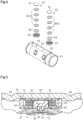
FIG. 4] FIG. 4 is a disassembled perspective view of an outer tube and a pressing mechanism included in the steering column device inFIG. 1 . - [
FIG. 5] FIG. 5 is an enlarged cross-sectional view of a vicinity of the pressing mechanism inFIG. 3 . - An embodiment of a steering column device will be described below with reference to the drawings.
- The steering column device 1 is installed in a vehicle so as to generally extend in a front-rear direction of the vehicle. In the following description, a left far side in
FIG. 1 is a front side of the vehicle, a right near side inFIG. 1 is a rear side of the vehicle, and orientations expressed in terms such as "front", "rear", "up", "down", "left", "right", and so forth, are defined with respect to the vehicle. - As illustrated in
FIG. 1 andFIG. 2 , the steering column device 1 includes acolumn shaft 2, asteering column 3 that rotatably accommodates thecolumn shaft 2, and abracket 4 that couples thesteering column 3 with a vehicle body S. Thecolumn shaft 2 and thesteering column 3 are disposed on a common axial line L. - A
steering wheel 5 is coupled with a rear-side end portion of thecolumn shaft 2. An intermediate shaft, omitted from illustration, is coupled with a front-side end portion of thecolumn shaft 2. The intermediate shaft is coupled with steered wheels via a rack and pinion mechanism that is omitted from illustration. Thebracket 4 is coupled with thesteering column 3 using a hinge bolt 6. Thesteering column 3 is capable of pivoting about the hinge bolt 6, in a state of being supported by the vehicle body S via thebracket 4. - The steering column device 1 is configured such that a position of the
steering wheel 5 in an up-down direction (hereinafter referred to as tilt position) and position of thesteering wheel 5 in the front-rear direction (hereinafter referred to as telescopic position) can be adjusted. The tilt position is adjusted by pivoting thesteering column 3 about the hinge bolt 6. The telescopic position is adjusted by telescoping of thesteering column 3. - The steering column device 1 includes a
tilt actuator 11 configured to pivot thesteering column 3 about the hinge bolt 6, and atelescopic actuator 12 configured to perform telescoping of thesteering column 3. Thetilt actuator 11 pivots thesteering column 3 via alink mechanism 13 to change the tilt position within a tilt adjustment range that is set in advance. Thetelescopic actuator 12 changes the telescopic position by performing telescoping of thesteering column 3 within a telescopic adjustment range that is set in advance. As an example, the telescopic adjustment range is set to a large range, such that thesteering wheel 5 can be retracted to a position where it is out of the way of a driver when the vehicle is in an automated driving mode, for example. - Next, a structure for enabling adjustment of the telescopic position will be described.
- As illustrated in
FIG. 2 , thecolumn shaft 2 includes anupper shaft 21 and alower shaft 22. Theupper shaft 21 has an elongated cylindrical shape. Thesteering wheel 5 is coupled with a rear-side end portion of theupper shaft 21. Thelower shaft 22 has an elongated columnar shape. Thelower shaft 22 is fitted to an inner peripheral portion of theupper shaft 21 through a spline engagement. Accordingly, thelower shaft 22 is coupled with theupper shaft 21 so as to be rotatable integrally with theupper shaft 21 and to be movable in an axial direction relative to theupper shaft 21. Note that it is sufficient for an arrangement to be capable of being regarded as a cylindrical shape as a whole to fall under the term "cylindrical shape" as used in the present specification, which includes a cylindrical shape formed by combining a plurality of parts, and a shape that is formed by partially notching out into a C-shaped part or the like. - As illustrated in
FIG. 2 andFIG. 3 , thesteering column 3 includes ahousing 31, acolumn tube 32, and a plurality ofpressing mechanisms 33. As an example, thesteering column 3 includes twopressing mechanisms 33, but the number of thepressing mechanisms 33 may be one, or three or more. Note that inFIG. 3 , members other than thecolumn shaft 2 and thesteering column 3 are omitted from illustration, for convenience of description. - The
housing 31 has a generally square-tube shape. Thehousing 31 is coupled with the vehicle body S via thebracket 4. Thehousing 31 rotatably supports thelower shaft 22 via abearing 34 provided at a front-side end portion thereof so as to be immovable relative thereto in the axial direction. Thecolumn tube 32 has a cylindrical shape. Thecolumn tube 32 rotatably supports theupper shaft 21 via abearing 35 provided at a rear-side end portion thereof so as to be immovable relative thereto in the axial direction. This enables thecolumn tube 32 to move integrally with theupper shaft 21 in the axial direction. Thecolumn tube 32 is accommodated in thehousing 31 so as to be movable in the axial direction. Thetelescopic actuator 12 is coupled with thecolumn tube 32 so as to be capable of moving thecolumn tube 32 in the axial direction. Thepressing mechanisms 33 are disposed between thehousing 31 and thecolumn tube 32. Thepressing mechanisms 33 are fixed to thecolumn tube 32, and also are configured to press against thehousing 31 from an inner side thereof. - Movement of the
column tube 32 in thehousing 31 in the axial direction causes thesteering column 3 to telescope. At this time, theupper shaft 21 moves in the axial direction with respect to thelower shaft 22 as thecolumn tube 32 moves, and accordingly thecolumn shaft 2 telescopes, and the telescopic position of thesteering wheel 5 changes. - The configurations of the
housing 31, thecolumn tube 32, and thepressing mechanism 33 will be described in detail below. - The
housing 31 includes a housingmain body 41 and acover 42. In one example, the housingmain body 41 has a substantially square-tube outer shape. The housingmain body 41 has aperipheral wall 44, and anend wall 45 provided at a front-side end portion of theperipheral wall 44. Theperipheral wall 44 has anopening 46 that opens on an upper side. Theopening 46 is rectangular, and opens generally the entire upper-side portion of theperipheral wall 44. Theperipheral wall 44 has a lower-side portion, a left-side portion, and a right-side portion, and a cross-section thereof that is orthogonal to the axial direction of theperipheral wall 44 is generally U-shaped. Theend wall 45 has a throughhole 47 extending therethrough in the axial direction. Thebearing 34 is provided in the throughhole 47. - The
cover 42 has a rectangular plate shape. Thecover 42 covers, generally theentire opening 46. Thecover 42 is fixed to the housingmain body 41 using a plurality of fixingbolts 48. Thecover 42 has tworibs 49 that extend in the axial direction. Theribs 49 extend over the entire region of thecover 42 in the axial direction. The tworibs 49 are provided spaced apart from each other in a width direction of the vehicle. Theribs 49 are formed by bending a part of thecover 42 so as to protrude downward. Note that theribs 49 are sometimes referred to as rails. A portion of an inner face of thecover 42 between theribs 49, i.e., a portion of the inner face of thecover 42 that is in contact with acontact pad 61, which will be described later, is flat and continues uninterrupted over the entire region of thecover 42 in the axial direction. - The
column tube 32 includes anouter tube 51, aninner tube 52 and asleeve 53. Theouter tube 51, theinner tube 52 and thesleeve 53 all have cylindrical shapes. Theouter tube 51 is disposed on a front side from theinner tube 52. As an example, theouter tube 51 may have a length in the axial direction with which theouter tube 51 does not protrude to the rear side from thehousing 31 in a state in which thesteering wheel 5 is adjusted to an optional telescopic position. A rear-side end portion of theinner tube 52 protrudes from thehousing 31. Thebearing 35 is provided at the rear-side end portion of theinner tube 52. A front-side end portion of theinner tube 52 is fitted to an inner periphery of a rear-side end portion of theouter tube 51. Thesleeve 53 is interposed between theouter tube 51 and theinner tube 52. - A part of an outer periphery of the
outer tube 51 is clinched toward theinner tube 52. Thus, theouter tube 51, theinner tube 52, and thesleeve 53 move integrally in the axial direction when the telescopic position of thesteering wheel 5 is being adjusted. On the other hand, when an impact load due to a vehicle collision or the like, for example, acts upon thesteering wheel 5, theinner tube 52 deforms thesleeve 53 and also moves in the axial direction with respect to theouter tube 51, thereby absorbing the impact load. - As illustrated in
FIG. 4 , an outer peripheral face of theouter tube 51 has aflat portion 54. Theflat portion 54 is provided on an upper-side portion of the outer peripheral face of theouter tube 51, and is provided over the entire region of theouter tube 51 in the axial direction. Theouter tube 51 has a plurality of attachingholes 55 that are opened in theflat portion 54. The attachingholes 55 are provided arrayed in the axial direction. - As illustrated in
FIG. 2 , thepressing mechanisms 33 are disposed on the outer periphery of theouter tube 51 with a spacing therebetween in the axial direction. Specifically, one of thepressing mechanisms 33 is disposed on a rear side from a middle position of theouter tube 51 in the axial direction, and the other is disposed on a front side from the middle position of theouter tube 51 in the axial direction. Thesepressing mechanisms 33 are configured in the same way, and accordingly thepressing mechanism 33 that is disposed on the rear side will be described, and description of thepressing mechanism 33 disposed on the front side will be omitted. - As illustrated in
FIG. 3 to FIG. 5 , thepressing mechanism 33 includes acontact pad 61, anelastic member 62, and aholder 63. Further, thepressing mechanism 33 includes awasher 64 that is ring-shaped. Theholder 63 is fixed to the outer peripheral face of theouter tube 51, and accommodates thecontact pad 61 and theelastic member 62. That is to say, thecontact pad 61 and theelastic member 62 are fixed to theouter tube 51, i.e., to thecolumn tube 32, via theholder 63. Theelastic member 62 biases thecontact pad 61 toward the inner face of thehousing 31. Thecontact pad 61 presses thehousing 31 from the inside thereof using the biasing force of theelastic member 62. - Specifically, the
holder 63 has a short cylindrical outer shape of which one end is closed off. Theholder 63 is made of a resin material, as one example. Specifically, theholder 63 has abottom wall 71 that is disk-shaped, and aperipheral wall 72 that has a cylindrical shape. An outside diameter of theperipheral wall 72 is smaller than a spacing between theribs 49 on thecover 42. An outer-side face of thebottom wall 71 has aninstallation face 73 that is flat. The middle of the outer-side face of thebottom wall 71 is recessed, and theinstallation face 73 has an annular shape. Theholder 63 also has a plurality ofprotrusions 74 protruding from the middle of the outer-side face of thebottom wall 71 and asingle support base 75 protruding from the middle of an inner-side face of thebottom wall 71. Eachprotrusion 74 protrudes outside of theholder 63 to a greater extent than theinstallation face 73. Theprotrusions 74 are disposed at equiangular intervals around the axial line of theholder 63. Theholder 63 is fixed to the outer peripheral face of theouter tube 51 by bringing theinstallation face 73 into contact with theflat portion 54 of theouter tube 51, and press-fitting theprotrusions 74 into the attaching holes 55. Theholder 63 is disposed between theribs 49 in a state of being fixed to the outer peripheral face of theouter tube 51. Thesupport base 75 has a columnar shape. The height of thesupport base 75 is lower than that of theperipheral wall 72. - A bore diameter of the
washer 64 is slightly larger than an outside diameter of thesupport base 75 and smaller than a bore diameter of theperipheral wall 72. Thewasher 64 is disposed on thebottom wall 71 while in a state of being fitted on an outer periphery of thesupport base 75. - The
elastic member 62 is a ring-shaped member. A bore diameter of theelastic member 62 is slightly larger than the outside diameter of thesupport base 75, and smaller than the bore diameter of theperipheral wall 72. For theelastic member 62, a stack of a plurality of disc springs is used as one example, but may be a coil spring or the like. Theelastic member 62 is disposed upon thewasher 64 in a state of being fitted to the outer periphery of thesupport base 75. - The
contact pad 61 is a member that is thin and disc-shaped. In one example, thecontact pad 61 is made of a resin material that has a low coefficient of friction and excellent sliding properties. An outside diameter of thecontact pad 61 is smaller than the bore diameter of theperipheral wall 72. That is to say, thewasher 64, theelastic member 62, and thecontact pad 61 are accommodated in theholder 63 in this order. Thecontact pad 61 is disposed within theperipheral wall 44 in a state of being in contact upon a distal end face of thesupport base 75. A thickness of thecontact pad 61 is greater than a difference between an amount of protrusion of theperipheral wall 44 and an amount of protrusion of thesupport base 75. Thus, thecontact pad 61 protrudes from a distal end face of theperipheral wall 72 in a state of being in contact with the distal end face of thesupport base 75, and is in contact with a flat portion on the inner face of thecover 42, between theribs 49. Note that thecontact pad 61 may be referred to as a slide plate. - In the
pressing mechanism 33 configured as described above, thecontact pad 61 presses the inner face of thecover 42 from an inner side thereof in the radial direction toward an outer side thereof, using the biasing force of theelastic member 62. Thecolumn tube 32 is pressed in the radial direction by a reaction force of thecontact pad 61 pressing thecover 42. This suppresses backlash of thecolumn tube 32 within thehousing 31. Also, when adjusting the telescopic position of thesteering wheel 5, thecontact pad 61 slides in the axial direction while in a state of being in contact with the inner face of thecover 42. - Next, the functions and effects of the present embodiment will be described.
- (1) The steering column device 1 includes the
column shaft 2 to which thesteering wheel 5 is fixed, and thesteering column 3 that rotatably supports thecolumn shaft 2. Thesteering column 3 includes thehousing 31 supported by the vehicle body S, thecolumn tube 32 accommodated in thehousing 31 so as to be movable in the axial direction, and thepressing mechanisms 33 disposed between thehousing 31 and thecolumn tube 32. Thepressing mechanisms 33 are fixed to thecolumn tube 32, and also are configured to press against thehousing 31 from the inner side thereof. Thepressing mechanisms 33 have thecontact pads 61 that come into contact with thehousing 31.
In the above configuration, thecontact pads 61 are fixed to thecolumn tube 32, and accordingly the positions of thecontact pads 61 as to thecolumn tube 32 do not change even when the telescopic position of thesteering wheel 5 changes. That is to say, the distance between the point of load of the pressing force acting on thecolumn tube 32 and thesteering wheel 5 does not change in accordance with the telescopic position. Accordingly, when an external force is applied to thesteering wheel 5 by an operation performed by the driver, for example, backlash of thecolumn tube 32 can be stably reduced, regardless of the telescopic position.
Also, the pressing force of thepressing mechanisms 33 can always be applied at an optimum position for reducing backlash of thecolumn tube 32. Accordingly, the pressing force acting on thehousing 31 can be suppressed from becoming excessive, and frictional force acting between thehousing 31 and thecontact pads 61 can be reduced. As a result, the load applied to thetelescopic actuator 12 when adjusting the telescopic position can be reduced. - (2) The
pressing mechanisms 33 further include theelastic members 62 that bias thecontact pads 61 toward thehousing 31. According to the above configuration, thecontact pads 61 press against thehousing 31 from the inner side thereof, using the biasing force of theelastic members 62. Accordingly, the force by which thecontact pads 61 press against thehousing 31, i.e., the magnitude of the pressing force acting upon thecolumn tube 32, can be suppressed from varying due to dimensional deviation of the component members of the steering column device 1. - (3) The
pressing mechanisms 33 further include theholders 63 that are fixed to an outer peripheral face of thecolumn tube 32, and that also accommodate thecontact pads 61 and theelastic members 62. According to the above configuration, thecontact pads 61 and theelastic members 62 can easily be integrally fixed to thecolumn tube 32. - (4) The outer peripheral face of the
column tube 32 includes theflat portion 54. Theholders 63 have installation faces 73 that are flat and that come into contact with theflat portion 54. According to the above configuration, theholders 63 can be stably fixed to the outer peripheral face of thecolumn tube 32. Thus, the force by which thecontact pads 61 press against thehousing 31 can be stabilized. - (5) The
housing 31 has the housingmain body 41 with theperipheral wall 44 that has theopening 46 passing therethrough in the radial direction, and thecover 42 that closes off theopening 46. Thecontact pads 61 are in contact with the inner face of thecover 42.
Regarding procedures for assembling thesteering column 3, in the above configuration, thecolumn tube 32 is first inserted into an inner side of the housingmain body 41, for example, and then thepressing mechanisms 33 are fixed to thecolumn tube 32 through theopening 46. Thereafter, thesteering column 3 is assembled by attaching thecover 42. Accordingly, thesteering column 3 can be assembled more easily than when thecolumn tube 32 with thepressing mechanisms 33 in a state of being fixed thereto, for example, is inserted into thehousing 31 from the rear side in the axial direction. - (6) The
holder 63 has thebottom wall 71, theperipheral wall 72, and thesupport base 75 projecting from thebottom wall 71 in the same direction as theperipheral wall 72. Thecontact pad 61 protrudes from the distal end face of theperipheral wall 72 in a state of being in contact with the distal end face of thesupport base 75. According to the above configuration, members other than thecontact pad 61, such as theperipheral wall 72 of theholder 63 and so forth, can be suppressed from coming into contact with thecover 42, for example, when vibration or the like is applied externally. Further, providing thesupport base 75 enables movement of theelastic member 62 and thewasher 64 in the radial direction due to external vibration to be restricted, and accordingly variance in pressing force can be suppressed. - (7) The
cover 42 has tworibs 49 extending in the axial direction, and theseribs 49 are provided spaced apart from each other in the vehicle width direction. Thecontact pad 61 is in contact with the flat portion between theribs 49 on the inner face of thecover 42. According to the above configuration, strength of thecover 42 can be improved by theribs 49. Further, thecontact pads 61 can be suppressed from sliding in a direction deviating from the axial line L when adjusting the telescopic position. - The present embodiment can be carried out modified as follows. The above embodiment and the following modifications can be combined insofar as no technical contradiction arises.
- In the above-described embodiment, the
entire cover 42 may have a flat shape, without theribs 49 being provided on thecover 42. - In the above-described embodiment, a configuration may be made in which the housing
main body 41 does not have theopening 46 and thehousing 31 does not include thecover 42. - In the above-described embodiment, the shape of the
holder 63 can be changed as appropriate, as long as thecontact pad 61 and theelastic member 62 can be accommodated. For example, theholder 63 may be configured without having thesupport base 75. Also, theholder 63 may be configured having a single protrusion that is press-fitted into the attachinghole 55, instead of themultiple protrusions 74. Further, theholder 63 may be configured without having theprotrusions 74. In this case, theholder 63 may be fixed to theouter tube 51 by an appropriate method, such as screws, adhesive agent, or the like, for example. - In the above embodiment, the
column tube 32 does not have to have theflat portion 54. Also, theholder 63 does not have to have theinstallation face 73 that is flat. - In the above embodiment, the
inner tube 52 may be directly fitted to an inner periphery of theouter tube 51, without thecolumn tube 32 including thesleeve 53. - In the above embodiment, the
pressing mechanism 33 does not have to include thewasher 64. Also, thepressing mechanism 33 does not have to include theelastic member 62. Further, thepressing mechanism 33 may be made up of just thecontact pad 61, without having theelastic member 62, thewasher 64 and theholder 63. In this case, thecontact pad 61 may press against thehousing 31 by, for example, the thickness of thecontact pad 61 being set such that thecontact pad 61 is compressed between thehousing 31 and thecolumn tube 32. - In the above-described embodiment, the steering column device 1 is configured to adjust the tilt position and the telescopic position by being electrically driven, but this is not restrictive, and a configuration may be made in which at least one of the tilt position and the telescopic position is manually adjusted. Alternatively, the steering column device 1 may be configured such that only the telescopic position can be adjusted.
Claims (5)
- A steering column device, comprising:a column shaft to which a steering wheel is fixed; anda steering column that rotatably supports the column shaft, wherein:the steering column includesa housing that is configured to be supported by a vehicle body,a column tube that is accommodated in the housing so as to be movable in an axial direction, anda contact pad that is disposed between the housing and the column tube; andthe contact pad is fixed to the column tube, and is also configured to press against the housing from an inner side.
- The steering column device according to claim 1, further comprising an elastic member that biases the contact pad toward the housing.
- The steering column device according to claim 2, further comprising a holder that is fixed to an outer peripheral face of the column tube, and that accommodates the contact pad and the elastic member.
- The steering column device according to claim 3, wherein:the outer peripheral face of the column tube includes a flat portion; andthe holder includes an installation face that is flat and that comes into contact with the flat portion.
- The steering column device according to any one of claims 1 to 4, wherein:the housing includesa housing main body that includes a peripheral wall with an opening passing through in a radial direction, anda cover that closes off the opening; andthe contact pad comes into contact with an inner face of the cover.
Applications Claiming Priority (1)
| Application Number | Priority Date | Filing Date | Title |
|---|---|---|---|
| PCT/JP2021/024245 WO2022269932A1 (en) | 2021-06-25 | 2021-06-25 | Steering column device |
Publications (3)
| Publication Number | Publication Date |
|---|---|
| EP4360995A1 true EP4360995A1 (en) | 2024-05-01 |
| EP4360995A4 EP4360995A4 (en) | 2024-08-21 |
| EP4360995B1 EP4360995B1 (en) | 2026-03-11 |
Family
ID=84544360
Family Applications (1)
| Application Number | Title | Priority Date | Filing Date |
|---|---|---|---|
| EP21947211.5A Active EP4360995B1 (en) | 2021-06-25 | 2021-06-25 | Steering column device |
Country Status (5)
| Country | Link |
|---|---|
| US (1) | US12195077B2 (en) |
| EP (1) | EP4360995B1 (en) |
| JP (1) | JP7589812B2 (en) |
| CN (1) | CN117396392A (en) |
| WO (1) | WO2022269932A1 (en) |
Families Citing this family (3)
| Publication number | Priority date | Publication date | Assignee | Title |
|---|---|---|---|---|
| BE1029838B1 (en) * | 2022-11-03 | 2024-05-30 | Thyssenkrupp Presta Ag | Steering column for a motor vehicle |
| GB2633410A (en) * | 2023-09-05 | 2025-03-12 | Zf Steering Systems Poland Sp Z O O | A steering column assembly for a vehicle |
| WO2025120735A1 (en) * | 2023-12-05 | 2025-06-12 | 株式会社ジェイテクト | Steering column device |
Family Cites Families (13)
| Publication number | Priority date | Publication date | Assignee | Title |
|---|---|---|---|---|
| JP2001315649A (en) | 2000-05-11 | 2001-11-13 | Nsk Ltd | Steering column support device |
| JP2005280654A (en) * | 2004-03-31 | 2005-10-13 | Fuji Kiko Co Ltd | Shock absorbing steering device |
| JP5465426B2 (en) * | 2008-12-19 | 2014-04-09 | 株式会社山田製作所 | Tilt telescopic steering device |
| JP2011042262A (en) * | 2009-08-21 | 2011-03-03 | Jtekt Corp | Steering column |
| JP2011046309A (en) * | 2009-08-27 | 2011-03-10 | Jtekt Corp | Steering device for vehicle |
| EP2724915B1 (en) * | 2012-05-25 | 2017-12-27 | NSK Ltd. | Position adjustment device for electric steering wheel |
| JP5865805B2 (en) * | 2012-09-05 | 2016-02-17 | Kyb株式会社 | Steering device |
| JP6529114B2 (en) * | 2015-02-27 | 2019-06-12 | 大豊工業株式会社 | Bearing and bearing device |
| JP2017165232A (en) * | 2016-03-16 | 2017-09-21 | 日本精工株式会社 | Steering device |
| JP6738536B2 (en) * | 2016-09-21 | 2020-08-12 | アイシン精機株式会社 | Vehicle steering system |
| JP6801334B2 (en) * | 2016-09-27 | 2020-12-16 | アイシン精機株式会社 | Vehicle steering device |
| CN109501852B (en) * | 2018-12-19 | 2021-07-30 | 芜湖世特瑞转向系统有限公司 | Electric four-way adjustable steering column |
| FR3103446A3 (en) * | 2019-11-22 | 2021-05-28 | Robert Bosch Automotive Steering Vendôme | steering column comprising a system for adjusting a relative position between two tubes |
-
2021
- 2021-06-25 WO PCT/JP2021/024245 patent/WO2022269932A1/en not_active Ceased
- 2021-06-25 US US18/562,540 patent/US12195077B2/en active Active
- 2021-06-25 JP JP2023529433A patent/JP7589812B2/en active Active
- 2021-06-25 CN CN202180098598.0A patent/CN117396392A/en active Pending
- 2021-06-25 EP EP21947211.5A patent/EP4360995B1/en active Active
Also Published As
| Publication number | Publication date |
|---|---|
| WO2022269932A1 (en) | 2022-12-29 |
| US20240239400A1 (en) | 2024-07-18 |
| JPWO2022269932A1 (en) | 2022-12-29 |
| EP4360995A4 (en) | 2024-08-21 |
| CN117396392A (en) | 2024-01-12 |
| WO2022269932A8 (en) | 2023-01-26 |
| EP4360995B1 (en) | 2026-03-11 |
| US12195077B2 (en) | 2025-01-14 |
| JP7589812B2 (en) | 2024-11-26 |
Similar Documents
| Publication | Publication Date | Title |
|---|---|---|
| EP4360995B1 (en) | Steering column device | |
| EP2431257B1 (en) | Steering device | |
| US8485554B2 (en) | Steering device | |
| EP3299253B1 (en) | Steering device of vehicle | |
| EP3173313B1 (en) | Electric power steering device | |
| EP3299254A1 (en) | Steering device of vehicle | |
| US9022426B2 (en) | Steering device | |
| US10967898B2 (en) | Motor-adjustable steering column for a motor vehicle | |
| US9834245B2 (en) | Steering device | |
| US20160355208A1 (en) | Steering device | |
| US20140311274A1 (en) | Steering column | |
| US20060021461A1 (en) | Vehicular steering apparatus | |
| US20210213998A1 (en) | Telescopic structure and steering column | |
| US10894558B2 (en) | Steering system | |
| US20200070869A1 (en) | Steering device | |
| US11524713B2 (en) | Steering column for a motor vehicle | |
| US11459015B2 (en) | Electrically adjustable steering column for a motor vehicle | |
| KR20120042328A (en) | Steering column for vehicle | |
| US11613300B2 (en) | Steering apparatus | |
| KR102076011B1 (en) | Steering structure of a vehicle | |
| US20220379948A1 (en) | Steering device | |
| KR20120134363A (en) | Steering column for vehicle |
Legal Events
| Date | Code | Title | Description |
|---|---|---|---|
| STAA | Information on the status of an ep patent application or granted ep patent |
Free format text: STATUS: THE INTERNATIONAL PUBLICATION HAS BEEN MADE |
|
| PUAI | Public reference made under article 153(3) epc to a published international application that has entered the european phase |
Free format text: ORIGINAL CODE: 0009012 |
|
| STAA | Information on the status of an ep patent application or granted ep patent |
Free format text: STATUS: REQUEST FOR EXAMINATION WAS MADE |
|
| 17P | Request for examination filed |
Effective date: 20231219 |
|
| AK | Designated contracting states |
Kind code of ref document: A1 Designated state(s): AL AT BE BG CH CY CZ DE DK EE ES FI FR GB GR HR HU IE IS IT LI LT LU LV MC MK MT NL NO PL PT RO RS SE SI SK SM TR |
|
| A4 | Supplementary search report drawn up and despatched |
Effective date: 20240718 |
|
| RIC1 | Information provided on ipc code assigned before grant |
Ipc: B62D 1/181 20060101ALI20240712BHEP Ipc: B62D 1/185 20060101AFI20240712BHEP |
|
| DAV | Request for validation of the european patent (deleted) | ||
| DAX | Request for extension of the european patent (deleted) | ||
| GRAP | Despatch of communication of intention to grant a patent |
Free format text: ORIGINAL CODE: EPIDOSNIGR1 |
|
| STAA | Information on the status of an ep patent application or granted ep patent |
Free format text: STATUS: GRANT OF PATENT IS INTENDED |
|
| INTG | Intention to grant announced |
Effective date: 20251009 |
|
| GRAS | Grant fee paid |
Free format text: ORIGINAL CODE: EPIDOSNIGR3 |
|
| GRAA | (expected) grant |
Free format text: ORIGINAL CODE: 0009210 |
|
| STAA | Information on the status of an ep patent application or granted ep patent |
Free format text: STATUS: THE PATENT HAS BEEN GRANTED |
|
| AK | Designated contracting states |
Kind code of ref document: B1 Designated state(s): AL AT BE BG CH CY CZ DE DK EE ES FI FR GB GR HR HU IE IS IT LI LT LU LV MC MK MT NL NO PL PT RO RS SE SI SK SM TR |
|
| REG | Reference to a national code |
Ref country code: CH Ref legal event code: F10 Free format text: ST27 STATUS EVENT CODE: U-0-0-F10-F00 (AS PROVIDED BY THE NATIONAL OFFICE) Effective date: 20260311 Ref country code: GB Ref legal event code: FG4D |
|
| REG | Reference to a national code |
Ref country code: DE Ref legal event code: R096 Ref document number: 602021049981 Country of ref document: DE |
|
| REG | Reference to a national code |
Ref country code: IE Ref legal event code: FG4D |
|
| PG25 | Lapsed in a contracting state [announced via postgrant information from national office to epo] |
Ref country code: RS Free format text: LAPSE BECAUSE OF FAILURE TO SUBMIT A TRANSLATION OF THE DESCRIPTION OR TO PAY THE FEE WITHIN THE PRESCRIBED TIME-LIMIT Effective date: 20260611 |
|
| PG25 | Lapsed in a contracting state [announced via postgrant information from national office to epo] |
Ref country code: ES Free format text: LAPSE BECAUSE OF FAILURE TO SUBMIT A TRANSLATION OF THE DESCRIPTION OR TO PAY THE FEE WITHIN THE PRESCRIBED TIME-LIMIT Effective date: 20260311 |
|
| PG25 | Lapsed in a contracting state [announced via postgrant information from national office to epo] |
Ref country code: GR Free format text: LAPSE BECAUSE OF FAILURE TO SUBMIT A TRANSLATION OF THE DESCRIPTION OR TO PAY THE FEE WITHIN THE PRESCRIBED TIME-LIMIT Effective date: 20260612 |
|
| REG | Reference to a national code |
Ref country code: LT Ref legal event code: MG9D |
|
| PG25 | Lapsed in a contracting state [announced via postgrant information from national office to epo] |
Ref country code: LT Free format text: LAPSE BECAUSE OF FAILURE TO SUBMIT A TRANSLATION OF THE DESCRIPTION OR TO PAY THE FEE WITHIN THE PRESCRIBED TIME-LIMIT Effective date: 20260311 |
|
| PGFP | Annual fee paid to national office [announced via postgrant information from national office to epo] |
Ref country code: DE Payment date: 20260529 Year of fee payment: 6 |
|
| PG25 | Lapsed in a contracting state [announced via postgrant information from national office to epo] |
Ref country code: NO Free format text: LAPSE BECAUSE OF FAILURE TO SUBMIT A TRANSLATION OF THE DESCRIPTION OR TO PAY THE FEE WITHIN THE PRESCRIBED TIME-LIMIT Effective date: 20260611 |
|
| PG25 | Lapsed in a contracting state [announced via postgrant information from national office to epo] |
Ref country code: SE Free format text: LAPSE BECAUSE OF FAILURE TO SUBMIT A TRANSLATION OF THE DESCRIPTION OR TO PAY THE FEE WITHIN THE PRESCRIBED TIME-LIMIT Effective date: 20260311 Ref country code: FI Free format text: LAPSE BECAUSE OF FAILURE TO SUBMIT A TRANSLATION OF THE DESCRIPTION OR TO PAY THE FEE WITHIN THE PRESCRIBED TIME-LIMIT Effective date: 20260311 |
|
| REG | Reference to a national code |
Ref country code: NL Ref legal event code: MP Effective date: 20260311 |
|
| PG25 | Lapsed in a contracting state [announced via postgrant information from national office to epo] |
Ref country code: HR Free format text: LAPSE BECAUSE OF FAILURE TO SUBMIT A TRANSLATION OF THE DESCRIPTION OR TO PAY THE FEE WITHIN THE PRESCRIBED TIME-LIMIT Effective date: 20260311 |
|
| PGFP | Annual fee paid to national office [announced via postgrant information from national office to epo] |
Ref country code: FR Payment date: 20260622 Year of fee payment: 6 |
|
| PG25 | Lapsed in a contracting state [announced via postgrant information from national office to epo] |
Ref country code: LV Free format text: LAPSE BECAUSE OF FAILURE TO SUBMIT A TRANSLATION OF THE DESCRIPTION OR TO PAY THE FEE WITHIN THE PRESCRIBED TIME-LIMIT Effective date: 20260311 |
|
| PG25 | Lapsed in a contracting state [announced via postgrant information from national office to epo] |
Ref country code: BG Free format text: LAPSE BECAUSE OF FAILURE TO SUBMIT A TRANSLATION OF THE DESCRIPTION OR TO PAY THE FEE WITHIN THE PRESCRIBED TIME-LIMIT Effective date: 20260311 |