EP4360959A1 - Vehicle uninterruptible power supply system and control method thereof - Google Patents
Vehicle uninterruptible power supply system and control method thereof Download PDFInfo
- Publication number
- EP4360959A1 EP4360959A1 EP23165005.2A EP23165005A EP4360959A1 EP 4360959 A1 EP4360959 A1 EP 4360959A1 EP 23165005 A EP23165005 A EP 23165005A EP 4360959 A1 EP4360959 A1 EP 4360959A1
- Authority
- EP
- European Patent Office
- Prior art keywords
- vehicle
- power supply
- voltage
- backup battery
- control circuit
- Prior art date
- Legal status (The legal status is an assumption and is not a legal conclusion. Google has not performed a legal analysis and makes no representation as to the accuracy of the status listed.)
- Pending
Links
Images



Classifications
-
- H—ELECTRICITY
- H02—GENERATION; CONVERSION OR DISTRIBUTION OF ELECTRIC POWER
- H02J—ELECTRIC POWER NETWORKS; CIRCUIT ARRANGEMENTS OR SYSTEMS FOR SUPPLYING OR DISTRIBUTING ELECTRIC POWER; SYSTEMS FOR STORING ELECTRIC ENERGY
- H02J7/00—Circuit arrangements for charging or discharging batteries or for supplying loads from batteries
- H02J7/34—Parallel operation in networks using both storage and other DC sources, e.g. providing buffering
- H02J7/342—The other DC source being a battery actively interacting with the first one, i.e. battery to battery charging
-
- B—PERFORMING OPERATIONS; TRANSPORTING
- B60—VEHICLES IN GENERAL
- B60R—VEHICLES, VEHICLE FITTINGS, OR VEHICLE PARTS, NOT OTHERWISE PROVIDED FOR
- B60R16/00—Electric or fluid circuits specially adapted for vehicles and not otherwise provided for; Arrangement of elements of electric or fluid circuits specially adapted for vehicles and not otherwise provided for
- B60R16/02—Electric or fluid circuits specially adapted for vehicles and not otherwise provided for; Arrangement of elements of electric or fluid circuits specially adapted for vehicles and not otherwise provided for electric constitutive elements
- B60R16/03—Electric or fluid circuits specially adapted for vehicles and not otherwise provided for; Arrangement of elements of electric or fluid circuits specially adapted for vehicles and not otherwise provided for electric constitutive elements for supply of electrical power to vehicle subsystems or for
-
- B—PERFORMING OPERATIONS; TRANSPORTING
- B60—VEHICLES IN GENERAL
- B60L—PROPULSION OF ELECTRICALLY-PROPELLED VEHICLES; SUPPLYING ELECTRIC POWER FOR AUXILIARY EQUIPMENT OF ELECTRICALLY-PROPELLED VEHICLES; ELECTRODYNAMIC BRAKE SYSTEMS FOR VEHICLES IN GENERAL; MAGNETIC SUSPENSION OR LEVITATION FOR VEHICLES; MONITORING OPERATING VARIABLES OF ELECTRICALLY-PROPELLED VEHICLES; ELECTRIC SAFETY DEVICES FOR ELECTRICALLY-PROPELLED VEHICLES
- B60L3/00—Electric devices on electrically-propelled vehicles for safety purposes; Monitoring operating variables, e.g. speed, deceleration or energy consumption
- B60L3/0023—Detecting, eliminating, remedying or compensating for drive train abnormalities, e.g. failures within the drive train
- B60L3/0046—Detecting, eliminating, remedying or compensating for drive train abnormalities, e.g. failures within the drive train relating to electric energy storage systems, e.g. batteries or capacitors
-
- B—PERFORMING OPERATIONS; TRANSPORTING
- B60—VEHICLES IN GENERAL
- B60R—VEHICLES, VEHICLE FITTINGS, OR VEHICLE PARTS, NOT OTHERWISE PROVIDED FOR
- B60R16/00—Electric or fluid circuits specially adapted for vehicles and not otherwise provided for; Arrangement of elements of electric or fluid circuits specially adapted for vehicles and not otherwise provided for
- B60R16/02—Electric or fluid circuits specially adapted for vehicles and not otherwise provided for; Arrangement of elements of electric or fluid circuits specially adapted for vehicles and not otherwise provided for electric constitutive elements
- B60R16/03—Electric or fluid circuits specially adapted for vehicles and not otherwise provided for; Arrangement of elements of electric or fluid circuits specially adapted for vehicles and not otherwise provided for electric constitutive elements for supply of electrical power to vehicle subsystems or for
- B60R16/033—Electric or fluid circuits specially adapted for vehicles and not otherwise provided for; Arrangement of elements of electric or fluid circuits specially adapted for vehicles and not otherwise provided for electric constitutive elements for supply of electrical power to vehicle subsystems or for characterised by the use of electrical cells or batteries
-
- H—ELECTRICITY
- H02—GENERATION; CONVERSION OR DISTRIBUTION OF ELECTRIC POWER
- H02J—ELECTRIC POWER NETWORKS; CIRCUIT ARRANGEMENTS OR SYSTEMS FOR SUPPLYING OR DISTRIBUTING ELECTRIC POWER; SYSTEMS FOR STORING ELECTRIC ENERGY
- H02J7/00—Circuit arrangements for charging or discharging batteries or for supplying loads from batteries
- H02J7/80—Circuit arrangements for charging or discharging batteries or for supplying loads from batteries including monitoring or indicating arrangements
-
- H—ELECTRICITY
- H02—GENERATION; CONVERSION OR DISTRIBUTION OF ELECTRIC POWER
- H02J—ELECTRIC POWER NETWORKS; CIRCUIT ARRANGEMENTS OR SYSTEMS FOR SUPPLYING OR DISTRIBUTING ELECTRIC POWER; SYSTEMS FOR STORING ELECTRIC ENERGY
- H02J7/00—Circuit arrangements for charging or discharging batteries or for supplying loads from batteries
- H02J7/90—Regulation of charging or discharging current or voltage
- H02J7/933—Regulation of charging or discharging current or voltage the cycle being controlled or terminated in response to electric parameters
-
- H—ELECTRICITY
- H02—GENERATION; CONVERSION OR DISTRIBUTION OF ELECTRIC POWER
- H02J—ELECTRIC POWER NETWORKS; CIRCUIT ARRANGEMENTS OR SYSTEMS FOR SUPPLYING OR DISTRIBUTING ELECTRIC POWER; SYSTEMS FOR STORING ELECTRIC ENERGY
- H02J9/00—Circuit arrangements for emergency or stand-by power supply, e.g. for emergency lighting
- H02J9/04—Circuit arrangements for emergency or stand-by power supply, e.g. for emergency lighting in which the distribution system is disconnected from the normal source and connected to a standby source
- H02J9/06—Circuit arrangements for emergency or stand-by power supply, e.g. for emergency lighting in which the distribution system is disconnected from the normal source and connected to a standby source with automatic change-over, e.g. UPS systems
- H02J9/061—Circuit arrangements for emergency or stand-by power supply, e.g. for emergency lighting in which the distribution system is disconnected from the normal source and connected to a standby source with automatic change-over, e.g. UPS systems for DC powered loads
-
- H—ELECTRICITY
- H02—GENERATION; CONVERSION OR DISTRIBUTION OF ELECTRIC POWER
- H02J—ELECTRIC POWER NETWORKS; CIRCUIT ARRANGEMENTS OR SYSTEMS FOR SUPPLYING OR DISTRIBUTING ELECTRIC POWER; SYSTEMS FOR STORING ELECTRIC ENERGY
- H02J9/00—Circuit arrangements for emergency or stand-by power supply, e.g. for emergency lighting
- H02J9/04—Circuit arrangements for emergency or stand-by power supply, e.g. for emergency lighting in which the distribution system is disconnected from the normal source and connected to a standby source
- H02J9/06—Circuit arrangements for emergency or stand-by power supply, e.g. for emergency lighting in which the distribution system is disconnected from the normal source and connected to a standby source with automatic change-over, e.g. UPS systems
- H02J9/068—Electronic means for switching from one power supply to another power supply, e.g. to avoid parallel connection
-
- H—ELECTRICITY
- H02—GENERATION; CONVERSION OR DISTRIBUTION OF ELECTRIC POWER
- H02J—ELECTRIC POWER NETWORKS; CIRCUIT ARRANGEMENTS OR SYSTEMS FOR SUPPLYING OR DISTRIBUTING ELECTRIC POWER; SYSTEMS FOR STORING ELECTRIC ENERGY
- H02J7/00—Circuit arrangements for charging or discharging batteries or for supplying loads from batteries
- H02J7/50—Circuit arrangements for charging or discharging batteries or for supplying loads from batteries acting upon multiple batteries simultaneously or sequentially
- H02J7/575—Parallel/serial switching of connection of batteries to charge or load circuit
-
- H—ELECTRICITY
- H02—GENERATION; CONVERSION OR DISTRIBUTION OF ELECTRIC POWER
- H02J—ELECTRIC POWER NETWORKS; CIRCUIT ARRANGEMENTS OR SYSTEMS FOR SUPPLYING OR DISTRIBUTING ELECTRIC POWER; SYSTEMS FOR STORING ELECTRIC ENERGY
- H02J7/00—Circuit arrangements for charging or discharging batteries or for supplying loads from batteries
- H02J7/90—Regulation of charging or discharging current or voltage
Definitions
- the present disclosure relates to a power management system and a power management method thereof, and more particularly to a vehicle uninterruptible power supply system and a control method thereof.
- a vehicle power supply can still provide power to a vehicle load for operation. Conversely, when the engine and the vehicle ignition are turned off, the vehicle power supply will stop supplying the power to the vehicle load.
- the present disclosure provides a vehicle uninterruptible power supply system and a control method thereof.
- the vehicle uninterruptible power supply system is adapted to a vehicle load and a vehicle power supply.
- the vehicle uninterruptible power supply system includes a control circuit, a charging and discharging circuit, and a backup battery.
- the control circuit is connected to the vehicle power supply and the vehicle load.
- the charging and discharging circuit is connected to the control circuit, and the backup battery is connected to the charging and discharging circuit and the control circuit.
- the control circuit receives an ignition-on signal, the control circuit instructs the charging and discharging circuit to use one of the vehicle power supply and the backup battery for charging the vehicle load according to a voltage of the vehicle power supply and a voltage of the backup battery.
- the control method includes: instructing, by a control circuit, a charging and discharging circuit to use one of a vehicle power supply and a backup battery for charging a vehicle load according to a voltage of the vehicle power supply and a voltage of the backup battery when the control circuit receives an ignition-on signal; instructing, by the control circuit, the charging and discharging circuit to use one of the vehicle power supply and the backup battery for charging the vehicle load according to the voltage of the backup battery when the control circuit receives an ignition-off signal; and preventing, by the control circuit, the vehicle power supply and the backup battery from charging the vehicle load when the control circuit receives the ignition-off signal and after the charging and discharging circuit uses one of the vehicle power supply and the backup battery to charge the vehicle load.
- time points at which the vehicle power supply and the backup battery charge and do not charge the vehicle load can be controlled in a programmable manner. Accordingly, power of the vehicle power supply can be prevented from being consumed by the vehicle load, so that the power of the vehicle power supply is sufficient for starting the engine again.
- connection in the context of the present disclosure means that there is a physical connection between two elements, and the two elements are directly or indirectly connected.
- FIG. 1 is a functional block diagram of a vehicle uninterruptible power supply system according to a first embodiment of the present disclosure.
- the vehicle uninterruptible power supply system is adapted to a vehicle power supply P and a vehicle load L.
- the vehicle uninterruptible power supply system includes, for example, a control circuit 1, a charging and discharging circuit 2, a first switch circuit 3, a second switch circuit 4, a backup battery 5, a first voltage detector VD1, and a second voltage detector VD2, but is not limited thereto.
- the control circuit 1 is connected to the vehicle power supply P, the vehicle load L, the charging and discharging circuit 2, the first switch circuit 3, the second switch circuit 4, the first voltage detector VD1, and the second voltage detector VD2.
- the charging and discharging circuit 2 is further connected to the first switch circuit 3, the second switch circuit 4, and the backup battery 5.
- the first switch circuit 3 is further connected to the vehicle power supply P.
- the second switch circuit 4 is further connected to the charging and discharging circuit 2 and the vehicle load L.
- the first voltage detector VD1 is connected to the vehicle power supply P, and the second voltage detector VD2 is connected to the backup battery 5.
- the control circuit 1 When a vehicle ignition that is in an off state is turned on, the control circuit 1 receives an ignition-on signal. Next, the control circuit 1 obtains a voltage of the vehicle power supply P by the first voltage detector VD1, and determines whether or not the voltage of the vehicle power supply P is less than a first voltage threshold (e.g., 12 volts). When the voltage of the vehicle power supply P is not less than the first voltage threshold, the control circuit 1 instructs the charging and discharging circuit 2 to use the vehicle power supply P to charge the vehicle load L. At this time, the charging and discharging circuit 2 does not use the backup battery 5 for charging the vehicle load L. When the voltage of the vehicle power supply P is less than the first voltage threshold, the control circuit 1 controls the first switch circuit 3 to be in the off state, so as to prevent the vehicle power supply P from charging the vehicle load L.
- a first voltage threshold e.g. 12 volts
- the control circuit 1 when the voltage of the vehicle power supply P is less than the first voltage threshold, the control circuit 1 further obtains a voltage of the backup battery 5 by the second voltage detector VD2, and determines whether or not the voltage of the backup battery 5 is less than a second voltage threshold (e.g., 9.8 volts). When the voltage of the backup battery 5 is less than the second voltage threshold, the control circuit 1 controls the second switch circuit 4 to be in the off state, so as to prevent the backup battery 5 from charging the vehicle load L. When the voltage of the backup battery 5 is not less than the second voltage threshold, the control circuit 1 instructs the charging and discharging circuit 2 to use the backup battery 5 for charging the vehicle load L. At this time, the charging and discharging circuit 2 does not use the vehicle power supply P to charge the vehicle load L.
- a second voltage threshold e.g. 9.8 volts
- the control circuit 1 When the vehicle ignition that is in an on state is turned off, the control circuit 1 receives an ignition-off signal. When the vehicle power supply P is used to charge the vehicle load L and the control circuit 1 receives the ignition-off signal, the counter 11 of the control circuit 1 is activated to start counting. Before a counting time of the counter 11 reaches a first time threshold and when the charging and discharging circuit 2 is using the vehicle power supply P to charge the backup battery 5, the control circuit 1 instructs the charging and discharging circuit 2 to stop using the vehicle power supply P for charging the backup battery 5.
- the control circuit 1 determines whether or not the voltage of the backup battery 5 is less than the second voltage threshold. When the voltage of the backup battery 5 is less than the second voltage threshold, the control circuit 1 instructs the charging and discharging circuit 2 to use the vehicle power supply P for charging the vehicle load L. At this time, the charging and discharging circuit 2 does not use the backup battery 5 to charge the vehicle load L. Conversely, when the voltage of the backup battery 5 is not less than the second voltage threshold, the control circuit 1 instructs the charging and discharging circuit 2 to use the backup battery 5 for charging the vehicle load P. At this time, the charging and discharging circuit 2 does not use the vehicle power supply P to charge the vehicle load L.
- the first time threshold e.g., 5 minutes
- the second time threshold e.g. 10 minutes
- the control circuit 1 When the counting time reaches the second time threshold and does not reach a third time threshold (e.g., 15 minutes), the control circuit 1 outputs the ignition-off signal to the vehicle load L. When the counting time reaches the third time threshold, the control circuit 1 controls the first switch circuit 3 and the second switch circuit 4 to be in the off state, so as to prevent the vehicle power supply P and the backup battery 5 from charging the vehicle load L.
- a third time threshold e.g. 15 minutes
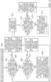
- FIG. 2 is a flowchart illustrating one example of a control method when an ignition-on event occurs to the vehicle uninterruptible power supply system of FIG. 1 .
- the control circuit 1 receives the ignition-on signal. Specifically, when the first switch circuit 3 and the second switch circuit 4 are in the off state and the vehicle ignition that is in the off state is turned on, the control circuit 1 receives the ignition-on signal from the vehicle power supply P.
- step S203 the control circuit 1 determines whether or not the voltage of the vehicle power supply P is less than the first voltage threshold (e.g., 12 volts). If the voltage of the vehicle power supply P is less than the first voltage threshold, step S203 is followed by step S205. If the voltage of the vehicle power supply P is not less than the first voltage threshold, step S203 is followed by step S207.
- step S205 the control circuit 1 determines whether or not the voltage of the backup battery 5 is less than the second voltage threshold (e.g., 9.8 volts).
- step S207 the control circuit 1 controls the first switch circuit 3 and the second switch circuit 4 to be in the on state, and instructs the charging and discharging circuit 2 to use the vehicle power supply P for charging the vehicle load L. At this time, the charging and discharging circuit 2 does not use the backup battery 5 to charge the vehicle load L.
- step S205 when the voltage of the backup battery 5 is less than the second voltage threshold, step S205 is followed by step S209.
- step S209 the control circuit 1 controls the first switch circuit 3 and the second switch circuit 4 to be in the off state, thereby preventing the vehicle power supply P and the backup battery 5 from charging the vehicle load L.
- step S209 the control method returns to step S203.
- step S211 the control circuit 1 instructs the charging and discharging circuit 2 to use the backup battery 5 for charging the vehicle load L. At this time, the charging and discharging circuit 2 does not use the vehicle power supply P to charge the vehicle load L. After step S211, the control method returns to step S203.
- Step S207 is followed by step S213.
- the control circuit 1 monitors the voltage of the backup battery 5.
- Step S213 is followed by step S215.
- step S215 the control circuit 1 determines whether or not the voltage of the backup battery 5 is less than the third voltage threshold (e.g., 14.7 volts). If the voltage of the backup battery 5 is less than the third voltage threshold, step S215 is followed by step S217. If the voltage of the backup battery 5 is not less than the third voltage threshold, step S215 is followed by step S219.
- step S217 the control circuit 1 instructs the charging and discharging circuit 2 to use the vehicle power supply P for charging the backup battery 5. After step S217, the control method returns to step S213.
- step S219 the control circuit 1 instructs the charging and discharging circuit 2 to use the vehicle power supply P for charging the vehicle load L. At this time, the charging and discharging circuit 2 does not use the backup battery 5 to charge the vehicle load L. After step S219, the control method returns to step S203.
- the vehicle uninterruptible power supply system monitors the voltage of the vehicle power supply P and the voltage of the backup battery 5. According to whether or not the voltage of the vehicle power supply P and the voltage of the backup battery 5 reach a preset voltage threshold, the vehicle uninterruptible power supply system uses the vehicle power supply P or the backup battery 5 to charge the vehicle load L. In this way, in addition to protecting the vehicle power supply P and the backup battery 5, the vehicle load L can continuously obtain power required for operation.
- FIG. 3 is a flowchart illustrating one example of the control method when an ignition-off event occurs to the vehicle uninterruptible power supply system of FIG. 1 .
- the control circuit 1 receives the ignition-off signal. Specifically, when the vehicle power supply P is used to charge the vehicle load L and the vehicle ignition that is in the on state is turned off, the control circuit 1 receives the ignition-off signal from the vehicle power supply P.
- step S303 the control circuit 1 determines whether or not the charging and discharging circuit 2 uses the vehicle power supply P to charge the backup battery 5. If the charging and discharging circuit 2 uses the vehicle power supply P to charge the backup battery 5, step S303 is followed by step S305. If the charging and discharging circuit 2 does not use the vehicle power supply P to charge the backup battery 5, step S303 is followed by step S307. In step S305, the control circuit 1 instructs the charging and discharging circuit 2 to stop charging the backup battery 5 by the vehicle power supply P, and activates the counter 11. In step S307, the counter 11 is activated.
- step S309 the counting time of the counter 11 reaches the first time threshold.
- step S311 the control circuit 1 determines whether or not the voltage of the backup battery 5 is less than the second voltage threshold. The second time threshold is greater than the first time threshold. If the voltage of the backup battery 5 is less than the second voltage threshold, step S311 is followed by step S313. If the voltage of the backup battery 5 is not less than the second voltage threshold, step S311 is followed by step S315. In step S313, the control circuit 1 instructs the charging and discharging circuit 2 to use the vehicle power supply P for charging the vehicle load L.
- step S315 the control circuit 1 instructs the charging and discharging circuit 2 to use the backup battery 5 for charging the vehicle load L. At this time, the charging and discharging circuit 2 does not use the vehicle power supply P to charge the vehicle load L.
- step S317 the counting time of the counter 11 reaches the second time threshold.
- step S317 is followed by step S319.
- step S319 the control circuit 1 outputs the ignition-off signal to the vehicle load L.
- step S321 the counting time of the counter 11 reaches the third time threshold.
- the third time threshold is greater than the second time threshold.
- step S323 the control circuit 1 controls the first switch circuit 3 and the second switch circuit 4 to be in the off state, thereby preventing the vehicle power supply P and the backup battery 5 from charging the vehicle load L.
- step S323 the control method returns to step S303.
- the vehicle uninterruptible power supply system does not immediately prevent the vehicle power supply P and the backup battery 5 from charging the vehicle load L. Firstly, charging of the backup battery 5 is stopped. Then, the vehicle load L is notified of the ignition-off event. After the vehicle load L learns that the vehicle ignition is turned off, the vehicle uninterruptible power supply system completely stops the vehicle power supply P and the backup battery 5 from charging the vehicle load L.
- FIG. 4 is a functional block diagram of the vehicle uninterruptible power supply system according to a second embodiment of the present disclosure.
- the vehicle uninterruptible power supply system of FIG. 4 further includes a network connection interface 6 and a cloud host 7.
- the network connection interface 6 can be, for example, a wired network interface or a wireless network interface.
- the network connection interface 6 is connected to the control circuit 1.
- the control circuit 1 is network-connected to the cloud host 7 by the network connection interface 6.
- the cloud host 7 receives input commands to adjust multiple parameters of the vehicle uninterruptible power supply system, and these parameters at least include the first voltage threshold, the second voltage threshold, the third voltage threshold, the first time threshold, the second time threshold, and the third time threshold.
- control circuit 1 periodically reports voltage states and current states of the vehicle power supply P, the backup battery 5, and the vehicle load L to the cloud host 7.
- control circuit 1 reports voltage states and current states of the vehicle power supply P, the backup battery 5, and the vehicle load L to the cloud host 7 every one second.
- FIG. 5 is a flowchart illustrating remote parameter configuration of the vehicle uninterruptible power supply system of FIG. 4 .
- the cloud host 7 receives the input command.
- the cloud host 7 transmits a parameter adjustment command to the control circuit 1.
- the parameter adjustment command includes, for example, adjusting the first voltage threshold, the second voltage threshold, the third voltage threshold, the first time threshold, the second time threshold, and the third time threshold.
- the control circuit 1 adjusts these parameters of the vehicle uninterruptible power supply system.
- time points at which the vehicle power supply and the backup battery charge and do not charge the vehicle load can be controlled in a programmable manner. Accordingly, power of the vehicle power supply can be prevented from being consumed by the vehicle load, so that the power of the vehicle power supply is sufficient for starting the engine again.
Landscapes
- Engineering & Computer Science (AREA)
- Power Engineering (AREA)
- Mechanical Engineering (AREA)
- Business, Economics & Management (AREA)
- Emergency Management (AREA)
- Life Sciences & Earth Sciences (AREA)
- Sustainable Development (AREA)
- Sustainable Energy (AREA)
- Transportation (AREA)
- Charge And Discharge Circuits For Batteries Or The Like (AREA)
- Electric Propulsion And Braking For Vehicles (AREA)
- Secondary Cells (AREA)
Abstract
Description
- The present disclosure relates to a power management system and a power management method thereof, and more particularly to a vehicle uninterruptible power supply system and a control method thereof.
- When an engine of a vehicle is turned off, as long as a vehicle ignition is turned on, a vehicle power supply can still provide power to a vehicle load for operation. Conversely, when the engine and the vehicle ignition are turned off, the vehicle power supply will stop supplying the power to the vehicle load.
- In certain particular situations, e.g., where a police car of an on-duty police officer is parked on a side of a road, in order to keep a digital image recorder installed in the police car running, the police officer usually turns off the engine, but does not turn off the vehicle ignition. However, since power consumption of the digital video recorder is large, if a driver does not pay attention to the remaining power of the vehicle power supply, the power of the vehicle power supply can be easily exhausted to the extent that the engine cannot be started again.
- In response to the above-referenced technical inadequacies, the present disclosure provides a vehicle uninterruptible power supply system and a control method thereof.
- In order to solve the above-mentioned problems, one of the technical aspects adopted by the present disclosure is to provide a vehicle uninterruptible power supply system. The vehicle uninterruptible power supply system is adapted to a vehicle load and a vehicle power supply. The vehicle uninterruptible power supply system includes a control circuit, a charging and discharging circuit, and a backup battery. The control circuit is connected to the vehicle power supply and the vehicle load. The charging and discharging circuit is connected to the control circuit, and the backup battery is connected to the charging and discharging circuit and the control circuit. When the control circuit receives an ignition-on signal, the control circuit instructs the charging and discharging circuit to use one of the vehicle power supply and the backup battery for charging the vehicle load according to a voltage of the vehicle power supply and a voltage of the backup battery.
- In order to solve the above-mentioned problems, another one of the technical aspects adopted by the present disclosure is to provide a control method of a vehicle uninterruptible power supply system. The control method includes: instructing, by a control circuit, a charging and discharging circuit to use one of a vehicle power supply and a backup battery for charging a vehicle load according to a voltage of the vehicle power supply and a voltage of the backup battery when the control circuit receives an ignition-on signal; instructing, by the control circuit, the charging and discharging circuit to use one of the vehicle power supply and the backup battery for charging the vehicle load according to the voltage of the backup battery when the control circuit receives an ignition-off signal; and preventing, by the control circuit, the vehicle power supply and the backup battery from charging the vehicle load when the control circuit receives the ignition-off signal and after the charging and discharging circuit uses one of the vehicle power supply and the backup battery to charge the vehicle load.
- Therefore, in the vehicle uninterruptible power supply system and the control method thereof provided by the present disclosure, time points at which the vehicle power supply and the backup battery charge and do not charge the vehicle load can be controlled in a programmable manner. Accordingly, power of the vehicle power supply can be prevented from being consumed by the vehicle load, so that the power of the vehicle power supply is sufficient for starting the engine again.
- These and other aspects of the present disclosure will become apparent from the following description of the embodiment taken in conjunction with the following drawings and their captions, although variations and modifications therein may be affected without departing from the spirit and scope of the novel concepts of the disclosure.
- The described embodiments may be better understood by reference to the following description and the accompanying drawings, in which:
-
FIG. 1 is a functional block diagram of a vehicle uninterruptible power supply system according to a first embodiment of the present disclosure; -
FIG. 2 is a flowchart illustrating one example of a control method when an ignition-on event occurs to the vehicle uninterruptible power supply system ofFIG. 1 ; -
FIG. 3 is a flowchart illustrating one example of the control method when an ignition-off event occurs to the vehicle uninterruptible power supply system ofFIG. 1 ; -
FIG. 4 is a functional block diagram of the vehicle uninterruptible power supply system according to a second embodiment of the present disclosure; and -
FIG. 5 is a flowchart illustrating remote parameter configuration of the vehicle uninterruptible power supply system ofFIG. 4 . - The present disclosure is more particularly described in the following examples that are intended as illustrative only since numerous modifications and variations therein will be apparent to those skilled in the art. Like numbers in the drawings indicate like components throughout the views. As used in the description herein and throughout the claims that follow, unless the context clearly dictates otherwise, the meaning of "a," "an" and "the" includes plural reference, and the meaning of "in" includes "in" and "on." Titles or subtitles can be used herein for the convenience of a reader, which shall have no influence on the scope of the present disclosure.
- The terms used herein generally have their ordinary meanings in the art. In the case of conflict, the present document, including any definitions given herein, will prevail. The same thing can be expressed in more than one way. Alternative language and synonyms can be used for any term(s) discussed herein, and no special significance is to be placed upon whether a term is elaborated or discussed herein. A recital of one or more synonyms does not exclude the use of other synonyms. The use of examples anywhere in this specification including examples of any terms is illustrative only, and in no way limits the scope and meaning of the present disclosure or of any exemplified term. Likewise, the present disclosure is not limited to various embodiments given herein. Numbering terms such as "first," "second" or "third" can be used to describe various components, signals or the like, which are for distinguishing one component/signal from another one only, and are not intended to, nor should be construed to impose any substantive limitations on the components, signals or the like. In addition, the term "connect" in the context of the present disclosure means that there is a physical connection between two elements, and the two elements are directly or indirectly connected.
-
FIG. 1 is a functional block diagram of a vehicle uninterruptible power supply system according to a first embodiment of the present disclosure. Referring toFIG 1 , the vehicle uninterruptible power supply system is adapted to a vehicle power supply P and a vehicle load L. The vehicle uninterruptible power supply system includes, for example, a control circuit 1, a charging and discharging circuit 2, a first switch circuit 3, asecond switch circuit 4, a backup battery 5, a first voltage detector VD1, and a second voltage detector VD2, but is not limited thereto. - The control circuit 1 is connected to the vehicle power supply P, the vehicle load L, the charging and discharging circuit 2, the first switch circuit 3, the
second switch circuit 4, the first voltage detector VD1, and the second voltage detector VD2. The charging and discharging circuit 2 is further connected to the first switch circuit 3, thesecond switch circuit 4, and the backup battery 5. The first switch circuit 3 is further connected to the vehicle power supply P. Thesecond switch circuit 4 is further connected to the charging and discharging circuit 2 and the vehicle load L. The first voltage detector VD1 is connected to the vehicle power supply P, and the second voltage detector VD2 is connected to the backup battery 5. - When a vehicle ignition that is in an off state is turned on, the control circuit 1 receives an ignition-on signal. Next, the control circuit 1 obtains a voltage of the vehicle power supply P by the first voltage detector VD1, and determines whether or not the voltage of the vehicle power supply P is less than a first voltage threshold (e.g., 12 volts). When the voltage of the vehicle power supply P is not less than the first voltage threshold, the control circuit 1 instructs the charging and discharging circuit 2 to use the vehicle power supply P to charge the vehicle load L. At this time, the charging and discharging circuit 2 does not use the backup battery 5 for charging the vehicle load L. When the voltage of the vehicle power supply P is less than the first voltage threshold, the control circuit 1 controls the first switch circuit 3 to be in the off state, so as to prevent the vehicle power supply P from charging the vehicle load L.
- Moreover, when the voltage of the vehicle power supply P is less than the first voltage threshold, the control circuit 1 further obtains a voltage of the backup battery 5 by the second voltage detector VD2, and determines whether or not the voltage of the backup battery 5 is less than a second voltage threshold (e.g., 9.8 volts). When the voltage of the backup battery 5 is less than the second voltage threshold, the control circuit 1 controls the
second switch circuit 4 to be in the off state, so as to prevent the backup battery 5 from charging the vehicle load L. When the voltage of the backup battery 5 is not less than the second voltage threshold, the control circuit 1 instructs the charging and discharging circuit 2 to use the backup battery 5 for charging the vehicle load L. At this time, the charging and discharging circuit 2 does not use the vehicle power supply P to charge the vehicle load L. - When the vehicle ignition that is in an on state is turned off, the control circuit 1 receives an ignition-off signal. When the vehicle power supply P is used to charge the vehicle load L and the control circuit 1 receives the ignition-off signal, the
counter 11 of the control circuit 1 is activated to start counting. Before a counting time of thecounter 11 reaches a first time threshold and when the charging and discharging circuit 2 is using the vehicle power supply P to charge the backup battery 5, the control circuit 1 instructs the charging and discharging circuit 2 to stop using the vehicle power supply P for charging the backup battery 5. - When the counting time of the
counter 11 reaches the first time threshold (e.g., 5 minutes) and does not reach the second time threshold (e.g., 10 minutes), the control circuit 1 determines whether or not the voltage of the backup battery 5 is less than the second voltage threshold. When the voltage of the backup battery 5 is less than the second voltage threshold, the control circuit 1 instructs the charging and discharging circuit 2 to use the vehicle power supply P for charging the vehicle load L. At this time, the charging and discharging circuit 2 does not use the backup battery 5 to charge the vehicle load L. Conversely, when the voltage of the backup battery 5 is not less than the second voltage threshold, the control circuit 1 instructs the charging and discharging circuit 2 to use the backup battery 5 for charging the vehicle load P. At this time, the charging and discharging circuit 2 does not use the vehicle power supply P to charge the vehicle load L. - When the counting time reaches the second time threshold and does not reach a third time threshold (e.g., 15 minutes), the control circuit 1 outputs the ignition-off signal to the vehicle load L. When the counting time reaches the third time threshold, the control circuit 1 controls the first switch circuit 3 and the
second switch circuit 4 to be in the off state, so as to prevent the vehicle power supply P and the backup battery 5 from charging the vehicle load L. -
FIG. 2 is a flowchart illustrating one example of a control method when an ignition-on event occurs to the vehicle uninterruptible power supply system ofFIG. 1 . Referring toFIG. 2 , in step S201, the control circuit 1 receives the ignition-on signal. Specifically, when the first switch circuit 3 and thesecond switch circuit 4 are in the off state and the vehicle ignition that is in the off state is turned on, the control circuit 1 receives the ignition-on signal from the vehicle power supply P. - In step S203, the control circuit 1 determines whether or not the voltage of the vehicle power supply P is less than the first voltage threshold (e.g., 12 volts). If the voltage of the vehicle power supply P is less than the first voltage threshold, step S203 is followed by step S205. If the voltage of the vehicle power supply P is not less than the first voltage threshold, step S203 is followed by step S207. In step S205, the control circuit 1 determines whether or not the voltage of the backup battery 5 is less than the second voltage threshold (e.g., 9.8 volts). In step S207, the control circuit 1 controls the first switch circuit 3 and the
second switch circuit 4 to be in the on state, and instructs the charging and discharging circuit 2 to use the vehicle power supply P for charging the vehicle load L. At this time, the charging and discharging circuit 2 does not use the backup battery 5 to charge the vehicle load L. - In step S205, when the voltage of the backup battery 5 is less than the second voltage threshold, step S205 is followed by step S209. When the voltage of the backup battery 5 is not less than the second voltage threshold, step S205 is followed by step S211. In step S209, the control circuit 1 controls the first switch circuit 3 and the
second switch circuit 4 to be in the off state, thereby preventing the vehicle power supply P and the backup battery 5 from charging the vehicle load L. After step S209, the control method returns to step S203. - In step S211, the control circuit 1 instructs the charging and discharging circuit 2 to use the backup battery 5 for charging the vehicle load L. At this time, the charging and discharging circuit 2 does not use the vehicle power supply P to charge the vehicle load L. After step S211, the control method returns to step S203.
- Step S207 is followed by step S213. In step S213, the control circuit 1 monitors the voltage of the backup battery 5. Step S213 is followed by step S215. In step S215, the control circuit 1 determines whether or not the voltage of the backup battery 5 is less than the third voltage threshold (e.g., 14.7 volts). If the voltage of the backup battery 5 is less than the third voltage threshold, step S215 is followed by step S217. If the voltage of the backup battery 5 is not less than the third voltage threshold, step S215 is followed by step S219. In step S217, the control circuit 1 instructs the charging and discharging circuit 2 to use the vehicle power supply P for charging the backup battery 5. After step S217, the control method returns to step S213. In step S219, the control circuit 1 instructs the charging and discharging circuit 2 to use the vehicle power supply P for charging the vehicle load L. At this time, the charging and discharging circuit 2 does not use the backup battery 5 to charge the vehicle load L. After step S219, the control method returns to step S203.
- Specifically, when the vehicle ignition is turned on, the vehicle uninterruptible power supply system monitors the voltage of the vehicle power supply P and the voltage of the backup battery 5. According to whether or not the voltage of the vehicle power supply P and the voltage of the backup battery 5 reach a preset voltage threshold, the vehicle uninterruptible power supply system uses the vehicle power supply P or the backup battery 5 to charge the vehicle load L. In this way, in addition to protecting the vehicle power supply P and the backup battery 5, the vehicle load L can continuously obtain power required for operation.
-
FIG. 3 is a flowchart illustrating one example of the control method when an ignition-off event occurs to the vehicle uninterruptible power supply system ofFIG. 1 . Referring toFIG. 3 , in step S301, the control circuit 1 receives the ignition-off signal. Specifically, when the vehicle power supply P is used to charge the vehicle load L and the vehicle ignition that is in the on state is turned off, the control circuit 1 receives the ignition-off signal from the vehicle power supply P. - In step S303, the control circuit 1 determines whether or not the charging and discharging circuit 2 uses the vehicle power supply P to charge the backup battery 5. If the charging and discharging circuit 2 uses the vehicle power supply P to charge the backup battery 5, step S303 is followed by step S305. If the charging and discharging circuit 2 does not use the vehicle power supply P to charge the backup battery 5, step S303 is followed by step S307. In step S305, the control circuit 1 instructs the charging and discharging circuit 2 to stop charging the backup battery 5 by the vehicle power supply P, and activates the
counter 11. In step S307, thecounter 11 is activated. - After step S305 and step S307, the control method proceeds to step S309. In step S309, the counting time of the
counter 11 reaches the first time threshold. In step S311, the control circuit 1 determines whether or not the voltage of the backup battery 5 is less than the second voltage threshold. The second time threshold is greater than the first time threshold. If the voltage of the backup battery 5 is less than the second voltage threshold, step S311 is followed by step S313. If the voltage of the backup battery 5 is not less than the second voltage threshold, step S311 is followed by step S315. In step S313, the control circuit 1 instructs the charging and discharging circuit 2 to use the vehicle power supply P for charging the vehicle load L. At this time, the charging and discharging circuit 2 does not use the backup battery 5 to charge the vehicle load L. In step S315, the control circuit 1 instructs the charging and discharging circuit 2 to use the backup battery 5 for charging the vehicle load L. At this time, the charging and discharging circuit 2 does not use the vehicle power supply P to charge the vehicle load L. - After step S313 and step S315, the control method proceeds to step S317. In step S317, the counting time of the
counter 11 reaches the second time threshold. Step S317 is followed by step S319. In step S319, the control circuit 1 outputs the ignition-off signal to the vehicle load L. In step S321, the counting time of thecounter 11 reaches the third time threshold. The third time threshold is greater than the second time threshold. In step S323, the control circuit 1 controls the first switch circuit 3 and thesecond switch circuit 4 to be in the off state, thereby preventing the vehicle power supply P and the backup battery 5 from charging the vehicle load L. After step S323, the control method returns to step S303. - Specifically, when the vehicle ignition is turned off, the vehicle uninterruptible power supply system does not immediately prevent the vehicle power supply P and the backup battery 5 from charging the vehicle load L. Firstly, charging of the backup battery 5 is stopped. Then, the vehicle load L is notified of the ignition-off event. After the vehicle load L learns that the vehicle ignition is turned off, the vehicle uninterruptible power supply system completely stops the vehicle power supply P and the backup battery 5 from charging the vehicle load L.
-
FIG. 4 is a functional block diagram of the vehicle uninterruptible power supply system according to a second embodiment of the present disclosure. Compared with the vehicle uninterruptible power supply system ofFIG. 1 , the vehicle uninterruptible power supply system ofFIG. 4 further includes a network connection interface 6 and acloud host 7. The network connection interface 6 can be, for example, a wired network interface or a wireless network interface. The network connection interface 6 is connected to the control circuit 1. The control circuit 1 is network-connected to thecloud host 7 by the network connection interface 6. Thecloud host 7 receives input commands to adjust multiple parameters of the vehicle uninterruptible power supply system, and these parameters at least include the first voltage threshold, the second voltage threshold, the third voltage threshold, the first time threshold, the second time threshold, and the third time threshold. Therefore, according to practical requirements, users can remotely adjust the parameters of the vehicle uninterruptible power supply system. In addition, the control circuit 1 periodically reports voltage states and current states of the vehicle power supply P, the backup battery 5, and the vehicle load L to thecloud host 7. For example, the control circuit 1 reports voltage states and current states of the vehicle power supply P, the backup battery 5, and the vehicle load L to thecloud host 7 every one second. -
FIG. 5 is a flowchart illustrating remote parameter configuration of the vehicle uninterruptible power supply system ofFIG. 4 . Referring toFIG. 5 , in step S501, thecloud host 7 receives the input command. In step S503, thecloud host 7 transmits a parameter adjustment command to the control circuit 1. The parameter adjustment command includes, for example, adjusting the first voltage threshold, the second voltage threshold, the third voltage threshold, the first time threshold, the second time threshold, and the third time threshold. However, the present disclosure is not limited thereto. In step S505, according to the parameter adjustment command, the control circuit 1 adjusts these parameters of the vehicle uninterruptible power supply system. - In conclusion, in the vehicle uninterruptible power supply system and the control method thereof provided by the present disclosure, time points at which the vehicle power supply and the backup battery charge and do not charge the vehicle load can be controlled in a programmable manner. Accordingly, power of the vehicle power supply can be prevented from being consumed by the vehicle load, so that the power of the vehicle power supply is sufficient for starting the engine again.
- The foregoing description of the exemplary embodiments of the disclosure has been presented only for the purposes of illustration and description and is not intended to be exhaustive or to limit the disclosure to the precise forms disclosed. Many modifications and variations are possible in light of the above teaching.
- The embodiments were chosen and described in order to explain the principles of the disclosure and their practical application so as to enable others skilled in the art to utilize the disclosure and various embodiments and with various modifications as are suited to the particular use contemplated. Alternative embodiments will become apparent to those skilled in the art to which the present disclosure pertains without departing from its spirit and scope.
Claims (10)
- A vehicle uninterruptible power supply system, which is adapted to a vehicle load (L) and a vehicle power supply (P), the vehicle uninterruptible power supply system characterized by comprising:a control circuit (1) connected to the vehicle power supply (P) and the vehicle load (L);a charging and discharging circuit (2) connected to the control circuit (1); anda backup battery (5) connected to the charging and discharging circuit (2) and the control circuit (1);wherein, when the control circuit (1) receives an ignition-on signal, the control circuit (1) instructs the charging and discharging circuit (2) to use one of the vehicle power supply (P) and the backup battery (5) for charging the vehicle load (L) according to a voltage of the vehicle power supply (P) and a voltage of the backup battery (5).
- The vehicle uninterruptible power supply system according to claim 1, wherein the control circuit (1) includes a counter (11), and the counter (11) is activated when the control circuit (1) receives an ignition-off signal; wherein, when a counting time of the counter (11) reaches a first time threshold, the control circuit (1) determines whether or not the voltage of the backup battery (5) is less a second voltage threshold; wherein, when the voltage of the backup battery (5) is less than the second voltage threshold, the charging and discharging circuit (2) uses the vehicle power supply (P) to charge the vehicle load (L); wherein, when the voltage of the backup battery (5) is not less than the second voltage threshold, the charging and discharging circuit (2) uses the backup battery (5) to charge the vehicle load (L).
- The vehicle uninterruptible power supply system according to claim 2, wherein, when the counting time reaches a second time threshold, the control circuit (1) outputs the ignition-off signal to the vehicle load (L); wherein, when the counting time reaches a third time threshold, the charging and discharging circuit (2) stops using the backup battery (5) to charge the vehicle load (L).
- The vehicle uninterruptible power supply system according to claim 1, wherein, when the vehicle power supply (P) is used to charge the vehicle load (L), the control circuit (1) determines whether or not the voltage of the backup battery (5) is less than a third voltage threshold; wherein, when the voltage of the backup battery (5) is less than the third voltage threshold, the charging and discharging circuit (2) charges the backup battery (5); wherein, when the voltage of the backup battery (5) is not less than the third voltage threshold, the charging and discharging circuit (2) uses the vehicle power supply to charge the vehicle load (L).
- The vehicle uninterruptible power supply system according to claim 3, further comprising a network connection interface (6) and a cloud host (7); wherein the network connection interface (6) is connected to the control circuit (1), the control circuit (1) is connected to the cloud host (7) by the network connection interface (6), and the cloud host (7) is configured to set a first voltage threshold, the second voltage threshold, the first time threshold, the second time threshold, and the third time threshold.
- A control method of a vehicle uninterruptible power supply system, comprising:instructing, by a control circuit (1), a charging and discharging circuit (2) to use one of a vehicle power supply (P) and a backup battery (5) for charging a vehicle load (L) according to a voltage of the vehicle power supply (P) and a voltage of the backup battery (5) when the control circuit (1) receives an ignition-on signal;instructing, by the control circuit (1), the charging and discharging circuit (2) to use one of the vehicle power supply (P) and the backup battery (5) for charging the vehicle load (L) according to the voltage of the backup battery (5) when the control circuit (1) receives an ignition-off signal; andpreventing, by the control circuit (1), the vehicle power supply (P) and the backup battery (5) from charging the vehicle load (L) when the control circuit (1) receives the ignition-off signal and after the charging and discharging circuit (2) uses one of the vehicle power supply (P) and the backup battery (5) to charge the vehicle load (L).
- The control method according to claim 6, wherein, when the control circuit (1) receives the ignition-on signal, the control circuit (1) determines whether or not the voltage of the vehicle power supply (P) is less than a first voltage threshold; wherein, when the voltage of the vehicle power supply (P) is not less than the first voltage threshold, the charging and discharging circuit (2) uses the vehicle power supply (P) to charge the vehicle load (L); wherein, when the voltage of the vehicle power supply (P) is less than the first voltage threshold, the control circuit (1) determines whether or not the voltage of the backup battery (5) is less than a second voltage threshold; wherein, when the voltage of the backup battery (5) is less than the second voltage threshold, the charging and discharging circuit (2) stops using the backup battery (5) to charge the vehicle load (L); wherein, when the voltage of the backup battery (5) is not less than the second voltage threshold, the charging and discharging circuit (2) uses the backup battery (5) to charge the vehicle load (L).
- The control method according to claim 6, wherein, when the control circuit (1) receives the ignition-off signal, a counter (11) of the control circuit (1) is activated; wherein, when a counting time of the counter (11) reaches a first time threshold, the control circuit (1) determines whether or not the voltage of the backup battery (5) is less than a second voltage threshold; wherein, when the voltage of the backup battery (5) is less than the second voltage threshold, the vehicle power supply (P) is used to charge the vehicle load (L); wherein, when the counting time reaches a second time threshold, the control circuit (1) outputs the ignition-off signal to the vehicle load (L); wherein, when the counting time reaches a third time threshold, the control circuit (1) prevents the vehicle power supply (P) and the backup battery (5) from charging the vehicle load (L).
- The control method according to claim 6, further comprising: determining, by the control circuit (1), whether or not the voltage of the backup battery (5) is less than a third voltage threshold when the vehicle power supply (P) is used to charge the vehicle load (L); wherein, when the voltage of the backup battery (5) is less than the third voltage threshold, the backup battery (5) starts to be charged; wherein, when the voltage of the backup battery (5) is not less than the third voltage threshold, the vehicle power supply (P) is used to charge the vehicle load (L).
- The control method according to claim 8, further comprising: network-connecting, by a cloud host (7), to the control circuit (1); wherein at least a first voltage threshold, the second voltage threshold, the first time threshold, the second time threshold, and the third time threshold are set by the cloud host (7).
Applications Claiming Priority (1)
| Application Number | Priority Date | Filing Date | Title |
|---|---|---|---|
| US202263420467P | 2022-10-28 | 2022-10-28 |
Publications (1)
| Publication Number | Publication Date |
|---|---|
| EP4360959A1 true EP4360959A1 (en) | 2024-05-01 |
Family
ID=85505394
Family Applications (3)
| Application Number | Title | Priority Date | Filing Date |
|---|---|---|---|
| EP23160161.8A Pending EP4360958A1 (en) | 2022-10-28 | 2023-03-06 | Vehicle power management system and operation method thereof |
| EP23165005.2A Pending EP4360959A1 (en) | 2022-10-28 | 2023-03-29 | Vehicle uninterruptible power supply system and control method thereof |
| EP23168232.9A Active EP4360960B1 (en) | 2022-10-28 | 2023-04-17 | Vehicle power management system and power management method thereof |
Family Applications Before (1)
| Application Number | Title | Priority Date | Filing Date |
|---|---|---|---|
| EP23160161.8A Pending EP4360958A1 (en) | 2022-10-28 | 2023-03-06 | Vehicle power management system and operation method thereof |
Family Applications After (1)
| Application Number | Title | Priority Date | Filing Date |
|---|---|---|---|
| EP23168232.9A Active EP4360960B1 (en) | 2022-10-28 | 2023-04-17 | Vehicle power management system and power management method thereof |
Country Status (6)
| Country | Link |
|---|---|
| US (4) | US12191704B2 (en) |
| EP (3) | EP4360958A1 (en) |
| CN (3) | CN117944598A (en) |
| AU (3) | AU2023201337B2 (en) |
| PL (1) | PL4360960T3 (en) |
| TW (2) | TWI868606B (en) |
Families Citing this family (1)
| Publication number | Priority date | Publication date | Assignee | Title |
|---|---|---|---|---|
| JP7120041B2 (en) * | 2019-01-22 | 2022-08-17 | 住友電装株式会社 | VEHICLE POWER CONTROL DEVICE AND VEHICLE POWER SUPPLY DEVICE |
Citations (8)
| Publication number | Priority date | Publication date | Assignee | Title |
|---|---|---|---|---|
| US9347414B2 (en) * | 2012-03-28 | 2016-05-24 | Bayerische Motoren Werke Aktiengesellschaft | Vehicle with an electric system architecture, and method for operating same |
| US20200259363A1 (en) * | 2016-10-14 | 2020-08-13 | Autonetworks Technologies, Ltd. | Vehicle-mounted backup device |
| US10910875B2 (en) * | 2016-10-19 | 2021-02-02 | Autonetworks Technologies, Ltd. | Vehicle backup device |
| US11059371B2 (en) * | 2017-03-27 | 2021-07-13 | Panasonic Intellectual Property Management Co., Ltd. | On-vehicle power supply device and vehicle having on-vehicle power supply device mounted thereon |
| US20210237670A1 (en) * | 2020-02-03 | 2021-08-05 | Toyota Jidosha Kabushiki Kaisha | Vehicle control device, method, program, and vehicle |
| US20220089111A1 (en) * | 2019-01-22 | 2022-03-24 | Sumitomo Wiring Systems, Ltd. | Vehicle power control apparatus and vehicle power apparatus |
| US20220103007A1 (en) * | 2020-02-14 | 2022-03-31 | Autonetworks Technologies, Ltd. | In-vehicle backup control apparatus and in-vehicle backup apparatus |
| US20220200311A1 (en) * | 2020-12-21 | 2022-06-23 | Yazaki Corporation | Backup Battery Control Module and Backup Battery Control System |
Family Cites Families (40)
| Publication number | Priority date | Publication date | Assignee | Title |
|---|---|---|---|---|
| US5899082A (en) * | 1997-09-18 | 1999-05-04 | Stein; Myron | Method and apparatus for odor elimination in vehicle air conditioning systems |
| CN1277748A (en) | 1997-10-27 | 2000-12-20 | 约翰逊控制技术公司 | Dual-battery electrical system charging control method and circuit |
| JP2001352687A (en) * | 2000-05-08 | 2001-12-21 | Sun-Lite Trading Ltd | Intelligent switch for battery |
| JP3981882B2 (en) * | 2003-03-05 | 2007-09-26 | 株式会社デンソー | Circuit protection device and airbag system |
| TWM313374U (en) | 2006-12-08 | 2007-06-01 | Aaeon Technology Inc | Monitoring/controlling system for vehicle-carried power source |
| JP2008290513A (en) * | 2007-05-23 | 2008-12-04 | Sanyo Electric Co Ltd | Power control device and on-vehicle electronic equipment system |
| US8125181B2 (en) | 2008-09-17 | 2012-02-28 | Toyota Motor Engineering & Manufacturing North America, Inc. | Method and apparatus for hybrid vehicle auxiliary battery state of charge control |
| TWM394254U (en) | 2010-06-01 | 2010-12-11 | Green Battery Technology Corp | Automobile battery module |
| WO2012125963A2 (en) * | 2011-03-16 | 2012-09-20 | Johnson Controls Technology Company | Energy source devices and systems having a battery and an ultracapacitor |
| JP2014512625A (en) * | 2011-04-22 | 2014-05-22 | エクスパナージー,エルエルシー | System and method for analyzing energy usage |
| US20150336468A1 (en) * | 2012-12-25 | 2015-11-26 | Toyota Jidosha Kabushiki Kaisha | Power supply system for vehicle, vehicle comprising the same, and method for controlling power supply system for vehicle |
| KR101315645B1 (en) * | 2013-04-17 | 2013-10-08 | 세방전지(주) | Dual battery control system and method thereof |
| GB2520556B (en) * | 2013-11-26 | 2016-05-25 | Ford Global Tech Llc | A method of controlling a mild hybrid electric vehicle |
| CN105703023A (en) | 2014-11-28 | 2016-06-22 | 奇点新源国际技术开发(北京)有限公司 | Charging-discharging method and apparatus for standby battery of vehicle-mounted terminal |
| CN104615037B (en) | 2014-12-22 | 2019-08-13 | 厦门雅迅网络股份有限公司 | Device and method for waking up vehicle-mounted equipment based on CAN bus |
| JP6308225B2 (en) * | 2016-01-13 | 2018-04-11 | トヨタ自動車株式会社 | In-vehicle power supply system |
| US10581259B2 (en) * | 2017-01-05 | 2020-03-03 | Denso International America, Inc. | Battery switching system |
| JP6875911B2 (en) * | 2017-03-31 | 2021-05-26 | 株式会社Subaru | Vehicle battery controller |
| CN107139774B (en) | 2017-04-18 | 2020-06-30 | 上海蔚来汽车有限公司 | Electric vehicle and its active discharge module, drive device, electric drive system |
| JP7017138B2 (en) * | 2018-12-03 | 2022-02-08 | 株式会社オートネットワーク技術研究所 | In-vehicle backup power supply control device and in-vehicle backup power supply |
| JP7108962B2 (en) * | 2018-12-03 | 2022-07-29 | 株式会社オートネットワーク技術研究所 | In-vehicle backup power supply control device and in-vehicle backup power supply device |
| GB201820073D0 (en) | 2018-12-10 | 2019-01-23 | Tomtom Telematics Bv | Vehicle battery monitoring |
| US11345253B2 (en) * | 2019-09-19 | 2022-05-31 | Nio Usa, Inc. | Vehicle power devices, systems, and methods for fail operational electronic control unit power management |
| TWI719690B (en) | 2019-10-28 | 2021-02-21 | 林裕舜 | Charging system for electric vehicles |
| CN110979221A (en) * | 2019-12-26 | 2020-04-10 | 长城汽车股份有限公司 | Power supply control method and device for vehicle and vehicle |
| KR20210120394A (en) * | 2020-03-26 | 2021-10-07 | 현대자동차주식회사 | Apparatus and method for controlling battery of vehicle |
| TW202142426A (en) | 2020-04-23 | 2021-11-16 | 泰茂實業股份有限公司 | Auxiliary power supply device for vehicle battery comprising a supercapacitor, a battery module, a switch module and a controller |
| CN111674346A (en) * | 2020-05-26 | 2020-09-18 | 长城汽车股份有限公司 | Battery charging method and system, vehicle |
| JP7327296B2 (en) * | 2020-06-30 | 2023-08-16 | トヨタ自動車株式会社 | VEHICLE CONTROL DEVICE, METHOD, PROGRAM, AND VEHICLE |
| JP7371580B2 (en) * | 2020-07-07 | 2023-10-31 | トヨタ自動車株式会社 | Vehicle control device, method, program, and vehicle |
| US12030437B2 (en) | 2020-07-30 | 2024-07-09 | Revivermx Inc. | Power and battery systems for a digital license plate |
| CN214590746U (en) | 2020-11-04 | 2021-11-02 | 山东东映出行科技有限公司 | Vehicle-mounted auxiliary battery charging controller |
| JP7453897B2 (en) | 2020-11-13 | 2024-03-21 | 本田技研工業株式会社 | Vehicle power supply device and control method for vehicle power supply device |
| US11760227B2 (en) * | 2021-02-15 | 2023-09-19 | Raymond Anthony Joao | Battery power management apparatus and method |
| US20240123839A1 (en) * | 2021-02-22 | 2024-04-18 | Vanmoof B.V. | Secondary Bicycle Drive Battery and Method |
| CN113852168B (en) | 2021-10-25 | 2024-11-08 | 奇瑞汽车股份有限公司 | Automobile power management method and device |
| TWM624892U (en) * | 2021-12-02 | 2022-03-21 | 廖元魁 | vehicle power supply system |
| US12370923B2 (en) * | 2022-06-27 | 2025-07-29 | Toyota Motor North America, Inc. | Electric vehicle auxiliary battery usage for energy consumption events |
| CN115230525B (en) * | 2022-06-29 | 2025-06-17 | 郑州森鹏电子技术股份有限公司 | Vehicle power management method, system and vehicle |
| CN115133620A (en) * | 2022-07-18 | 2022-09-30 | 珠海冠宇动力电源有限公司 | Power supply circuit, control method and device thereof, and medium |
-
2022
- 2022-12-06 CN CN202211577838.8A patent/CN117944598A/en active Pending
-
2023
- 2023-03-03 AU AU2023201337A patent/AU2023201337B2/en active Active
- 2023-03-03 TW TW112107716A patent/TWI868606B/en active
- 2023-03-03 TW TW112107695A patent/TWI813529B/en active
- 2023-03-03 CN CN202310199963.8A patent/CN117955224A/en active Pending
- 2023-03-03 CN CN202310200003.9A patent/CN117944599A/en active Pending
- 2023-03-06 EP EP23160161.8A patent/EP4360958A1/en active Pending
- 2023-03-08 US US18/180,808 patent/US12191704B2/en active Active
- 2023-03-28 AU AU2023201891A patent/AU2023201891B2/en active Active
- 2023-03-29 EP EP23165005.2A patent/EP4360959A1/en active Pending
- 2023-04-06 US US18/296,969 patent/US12206277B2/en active Active
- 2023-04-12 AU AU2023202261A patent/AU2023202261B1/en active Active
- 2023-04-17 US US18/301,972 patent/US12051938B2/en active Active
- 2023-04-17 PL PL23168232.9T patent/PL4360960T3/en unknown
- 2023-04-17 EP EP23168232.9A patent/EP4360960B1/en active Active
-
2024
- 2024-08-14 US US18/805,492 patent/US20240405594A1/en active Pending
Patent Citations (8)
| Publication number | Priority date | Publication date | Assignee | Title |
|---|---|---|---|---|
| US9347414B2 (en) * | 2012-03-28 | 2016-05-24 | Bayerische Motoren Werke Aktiengesellschaft | Vehicle with an electric system architecture, and method for operating same |
| US20200259363A1 (en) * | 2016-10-14 | 2020-08-13 | Autonetworks Technologies, Ltd. | Vehicle-mounted backup device |
| US10910875B2 (en) * | 2016-10-19 | 2021-02-02 | Autonetworks Technologies, Ltd. | Vehicle backup device |
| US11059371B2 (en) * | 2017-03-27 | 2021-07-13 | Panasonic Intellectual Property Management Co., Ltd. | On-vehicle power supply device and vehicle having on-vehicle power supply device mounted thereon |
| US20220089111A1 (en) * | 2019-01-22 | 2022-03-24 | Sumitomo Wiring Systems, Ltd. | Vehicle power control apparatus and vehicle power apparatus |
| US20210237670A1 (en) * | 2020-02-03 | 2021-08-05 | Toyota Jidosha Kabushiki Kaisha | Vehicle control device, method, program, and vehicle |
| US20220103007A1 (en) * | 2020-02-14 | 2022-03-31 | Autonetworks Technologies, Ltd. | In-vehicle backup control apparatus and in-vehicle backup apparatus |
| US20220200311A1 (en) * | 2020-12-21 | 2022-06-23 | Yazaki Corporation | Backup Battery Control Module and Backup Battery Control System |
Also Published As
| Publication number | Publication date |
|---|---|
| US12051938B2 (en) | 2024-07-30 |
| AU2023201337B2 (en) | 2024-11-07 |
| PL4360960T3 (en) | 2025-03-31 |
| TW202418207A (en) | 2024-05-01 |
| CN117944599A (en) | 2024-04-30 |
| US12191704B2 (en) | 2025-01-07 |
| EP4360960B1 (en) | 2024-11-27 |
| US12206277B2 (en) | 2025-01-21 |
| CN117955224A (en) | 2024-04-30 |
| AU2023201337A1 (en) | 2024-05-16 |
| CN117944598A (en) | 2024-04-30 |
| AU2023201891B2 (en) | 2024-10-24 |
| US20240146091A1 (en) | 2024-05-02 |
| TWI868606B (en) | 2025-01-01 |
| US20240405594A1 (en) | 2024-12-05 |
| TWI813529B (en) | 2023-08-21 |
| AU2023202261B1 (en) | 2024-02-01 |
| US20240146097A1 (en) | 2024-05-02 |
| EP4360960A1 (en) | 2024-05-01 |
| AU2023201891A1 (en) | 2024-05-16 |
| EP4360958A1 (en) | 2024-05-01 |
| US20240146098A1 (en) | 2024-05-02 |
| TW202417290A (en) | 2024-05-01 |
Similar Documents
| Publication | Publication Date | Title |
|---|---|---|
| JP4577274B2 (en) | Vehicle power supply system | |
| EP4365015A1 (en) | Vehicle control method and apparatus, and vehicle | |
| EP3581431A1 (en) | Charging control device for charging electric vehicle | |
| US20070032915A1 (en) | Engine control apparatus, control method and control system | |
| EP4360959A1 (en) | Vehicle uninterruptible power supply system and control method thereof | |
| US20020169991A1 (en) | Mobile data system having automated shutdown | |
| CN112977064A (en) | Low-power charging control system and control method for low-voltage storage battery | |
| US5764031A (en) | Method and apparatus for supplying a power source to an electronic apparatus | |
| CN118358397B (en) | Vehicle charging methods, devices, vehicles and storage media | |
| EP2635799A1 (en) | Activation device and activation method for a dual-battery system | |
| US7620486B2 (en) | Systems for providing an automobile electronic transmission control monitoring unit with a latchdown mechanism | |
| CN112706712A (en) | Standby control method and device for vehicle-mounted host and vehicle | |
| CN107128179A (en) | DC transformer starting control device of electric automobile | |
| EP4159518B1 (en) | Dcdc output voltage control method and control system for hybrid vehicle | |
| KR102730540B1 (en) | System and method for reserved charging battery of vehicle | |
| JP2002247777A (en) | Battery charging control device | |
| CN109802461B (en) | Multi-mode output power supply circuit for engineering machinery, power supply control system and control method thereof | |
| US20250325778A1 (en) | Method for Operating a Sleep Assistant During a Charging Process of a Vehicle, Computer-Readable Medium, System, and Vehicle | |
| CN118124508A (en) | Whole vehicle power-on and power-off time sequence control method | |
| CN109383425B (en) | Power supply system, method and device of fuel intelligent automobile and storage medium | |
| CN119858448B (en) | Methods and devices for managing low-voltage batteries | |
| JP2500592B2 (en) | Uninterruptible power system | |
| CN114256946B (en) | Power supply management system and power supply management method | |
| KR102634236B1 (en) | Charging system including charge restart function of electric vehicle | |
| US20260042351A1 (en) | Method for maintaining operation of ldc converter in communication failure state |
Legal Events
| Date | Code | Title | Description |
|---|---|---|---|
| PUAI | Public reference made under article 153(3) epc to a published international application that has entered the european phase |
Free format text: ORIGINAL CODE: 0009012 |
|
| STAA | Information on the status of an ep patent application or granted ep patent |
Free format text: STATUS: THE APPLICATION HAS BEEN PUBLISHED |
|
| AK | Designated contracting states |
Kind code of ref document: A1 Designated state(s): AL AT BE BG CH CY CZ DE DK EE ES FI FR GB GR HR HU IE IS IT LI LT LU LV MC ME MK MT NL NO PL PT RO RS SE SI SK SM TR |
|
| STAA | Information on the status of an ep patent application or granted ep patent |
Free format text: STATUS: REQUEST FOR EXAMINATION WAS MADE |
|
| 17P | Request for examination filed |
Effective date: 20240923 |
|
| RBV | Designated contracting states (corrected) |
Designated state(s): AL AT BE BG CH CY CZ DE DK EE ES FI FR GB GR HR HU IE IS IT LI LT LU LV MC ME MK MT NL NO PL PT RO RS SE SI SK SM TR |