EP4360931A1 - Vehicle panel component - Google Patents
Vehicle panel component Download PDFInfo
- Publication number
- EP4360931A1 EP4360931A1 EP23186038.8A EP23186038A EP4360931A1 EP 4360931 A1 EP4360931 A1 EP 4360931A1 EP 23186038 A EP23186038 A EP 23186038A EP 4360931 A1 EP4360931 A1 EP 4360931A1
- Authority
- EP
- European Patent Office
- Prior art keywords
- sections
- parallel lines
- plural
- section
- equal
- Prior art date
- Legal status (The legal status is an assumption and is not a legal conclusion. Google has not performed a legal analysis and makes no representation as to the accuracy of the status listed.)
- Granted
Links
Images


Classifications
-
- B—PERFORMING OPERATIONS; TRANSPORTING
- B60—VEHICLES IN GENERAL
- B60K—ARRANGEMENT OR MOUNTING OF PROPULSION UNITS OR OF TRANSMISSIONS IN VEHICLES; ARRANGEMENT OR MOUNTING OF PLURAL DIVERSE PRIME-MOVERS IN VEHICLES; AUXILIARY DRIVES FOR VEHICLES; INSTRUMENTATION OR DASHBOARDS FOR VEHICLES; ARRANGEMENTS IN CONNECTION WITH COOLING, AIR INTAKE, GAS EXHAUST OR FUEL SUPPLY OF PROPULSION UNITS IN VEHICLES
- B60K37/00—Dashboards
- B60K37/20—Dashboard panels
-
- B—PERFORMING OPERATIONS; TRANSPORTING
- B60—VEHICLES IN GENERAL
- B60K—ARRANGEMENT OR MOUNTING OF PROPULSION UNITS OR OF TRANSMISSIONS IN VEHICLES; ARRANGEMENT OR MOUNTING OF PLURAL DIVERSE PRIME-MOVERS IN VEHICLES; AUXILIARY DRIVES FOR VEHICLES; INSTRUMENTATION OR DASHBOARDS FOR VEHICLES; ARRANGEMENTS IN CONNECTION WITH COOLING, AIR INTAKE, GAS EXHAUST OR FUEL SUPPLY OF PROPULSION UNITS IN VEHICLES
- B60K35/00—Instruments specially adapted for vehicles; Arrangement of instruments in or on vehicles
- B60K35/20—Output arrangements, i.e. from vehicle to user, associated with vehicle functions or specially adapted therefor
- B60K35/21—Output arrangements, i.e. from vehicle to user, associated with vehicle functions or specially adapted therefor using visual output, e.g. blinking lights or matrix displays
- B60K35/215—Output arrangements, i.e. from vehicle to user, associated with vehicle functions or specially adapted therefor using visual output, e.g. blinking lights or matrix displays characterised by the combination of multiple visual outputs, e.g. combined instruments with analogue meters and additional displays
-
- B—PERFORMING OPERATIONS; TRANSPORTING
- B60—VEHICLES IN GENERAL
- B60K—ARRANGEMENT OR MOUNTING OF PROPULSION UNITS OR OF TRANSMISSIONS IN VEHICLES; ARRANGEMENT OR MOUNTING OF PLURAL DIVERSE PRIME-MOVERS IN VEHICLES; AUXILIARY DRIVES FOR VEHICLES; INSTRUMENTATION OR DASHBOARDS FOR VEHICLES; ARRANGEMENTS IN CONNECTION WITH COOLING, AIR INTAKE, GAS EXHAUST OR FUEL SUPPLY OF PROPULSION UNITS IN VEHICLES
- B60K35/00—Instruments specially adapted for vehicles; Arrangement of instruments in or on vehicles
- B60K35/40—Instruments specially adapted for improving the visibility thereof to the user, e.g. fogging prevention or anti-reflection arrangements
- B60K35/425—Anti-reflection arrangements
-
- B—PERFORMING OPERATIONS; TRANSPORTING
- B62—LAND VEHICLES FOR TRAVELLING OTHERWISE THAN ON RAILS
- B62J—CYCLE SADDLES OR SEATS; AUXILIARY DEVICES OR ACCESSORIES SPECIALLY ADAPTED TO CYCLES AND NOT OTHERWISE PROVIDED FOR, e.g. ARTICLE CARRIERS OR CYCLE PROTECTORS
- B62J50/00—Arrangements specially adapted for use on cycles not provided for in main groups B62J1/00 - B62J45/00
- B62J50/20—Information-providing devices
- B62J50/21—Information-providing devices intended to provide information to rider or passenger
- B62J50/22—Information-providing devices intended to provide information to rider or passenger electronic, e.g. displays
-
- B—PERFORMING OPERATIONS; TRANSPORTING
- B60—VEHICLES IN GENERAL
- B60K—ARRANGEMENT OR MOUNTING OF PROPULSION UNITS OR OF TRANSMISSIONS IN VEHICLES; ARRANGEMENT OR MOUNTING OF PLURAL DIVERSE PRIME-MOVERS IN VEHICLES; AUXILIARY DRIVES FOR VEHICLES; INSTRUMENTATION OR DASHBOARDS FOR VEHICLES; ARRANGEMENTS IN CONNECTION WITH COOLING, AIR INTAKE, GAS EXHAUST OR FUEL SUPPLY OF PROPULSION UNITS IN VEHICLES
- B60K2360/00—Indexing scheme associated with groups B60K35/00 or B60K37/00 relating to details of instruments or dashboards
- B60K2360/60—Structural details of dashboards or instruments
- B60K2360/68—Features of instruments
- B60K2360/688—Frames or decorative parts
-
- B—PERFORMING OPERATIONS; TRANSPORTING
- B60—VEHICLES IN GENERAL
- B60K—ARRANGEMENT OR MOUNTING OF PROPULSION UNITS OR OF TRANSMISSIONS IN VEHICLES; ARRANGEMENT OR MOUNTING OF PLURAL DIVERSE PRIME-MOVERS IN VEHICLES; AUXILIARY DRIVES FOR VEHICLES; INSTRUMENTATION OR DASHBOARDS FOR VEHICLES; ARRANGEMENTS IN CONNECTION WITH COOLING, AIR INTAKE, GAS EXHAUST OR FUEL SUPPLY OF PROPULSION UNITS IN VEHICLES
- B60K2360/00—Indexing scheme associated with groups B60K35/00 or B60K37/00 relating to details of instruments or dashboards
- B60K2360/60—Structural details of dashboards or instruments
- B60K2360/68—Features of instruments
- B60K2360/693—Cover plate features
-
- B—PERFORMING OPERATIONS; TRANSPORTING
- B60—VEHICLES IN GENERAL
- B60K—ARRANGEMENT OR MOUNTING OF PROPULSION UNITS OR OF TRANSMISSIONS IN VEHICLES; ARRANGEMENT OR MOUNTING OF PLURAL DIVERSE PRIME-MOVERS IN VEHICLES; AUXILIARY DRIVES FOR VEHICLES; INSTRUMENTATION OR DASHBOARDS FOR VEHICLES; ARRANGEMENTS IN CONNECTION WITH COOLING, AIR INTAKE, GAS EXHAUST OR FUEL SUPPLY OF PROPULSION UNITS IN VEHICLES
- B60K2360/00—Indexing scheme associated with groups B60K35/00 or B60K37/00 relating to details of instruments or dashboards
- B60K2360/92—Manufacturing of instruments
Definitions
- the present invention relates to a vehicle panel component.
- the panel face of the meter panel or so forth has a decorative function; hence, a vehicle panel component, having such a panel face, is desired to be enhanced in texture of the panel face thereof.
- a vehicle panel component includes a panel face.
- the panel face is divided into a plurality of sections.
- Each of the plurality of sections is made in shape of a polygon.
- the plurality of sections are disposed in adjacent to each other.
- the each of the plurality of sections includes a plurality of parallel lines disposed therewithin.
- the plurality of parallel lines are formed by a plurality of recesses and protrusions. A pattern of the plurality of parallel lines is different between adjacent sections of the plurality of sections.
- the panel face is divided into the plurality of sections, each of which is made in shape of a polygon.
- the plurality of parallel lines, disposed in each of the plurality of sections, are formed by the plurality of recesses and protrusions.
- a pattern of the plurality of parallel lines is different between adjacent sections of the plurality of sections.
- a stereoscopic shape is formed by a plurality of steps formed by the plurality of recesses and protrusions in each of the plurality of sections; hence, reflected light, entering the eyes of a rider, is changed in range and intensity.
- the reflected light stands out in relative movement between the eyes of the rider and the plurality of steps formed by the plurality of recesses and protrusions.
- the pattern of the plurality of parallel lines is different between adjacent sections of the plurality of sections; hence, the reflected light on the adjacent section of the plurality of sections appears to change in a different manner from each other.
- the adjacent section of the plurality of sections appears to change in different manners from each other in accordance with change in angle of reflection of external light or change in point of view of the rider; hence, such a visual effect as a lenticular image or hologram can be obtained on the panel face.
- enhancement in texture of the panel face can be achieved with a simple configuration.
- each of the plurality of sections is made in shape of a polygon; hence, further enhancement in texture of the panel face can be achieved with a simple configuration.
- An angle of the plurality of parallel lines is different between the adjacent sections of the plurality of sections.
- the adjacent sections of the plurality of sections can be made appear to change in different manners from each other in accordance with change in angle of reflection of external light or change in point of view of the rider with a simple configuration.
- the each of the plurality of sections may be made in shape of a triangle. In this case, it is made easy to recognize the shape of the each of the plurality of sections; hence, it is made easier to obtain such a visual effect as a lenticular image or hologram on the panel face.
- the each of the plurality of sections may be made in shape of an acute-angled triangle. In this case, it is made easy to recognize the shape of the each of the plurality of sections; hence, it is made easier to obtain such a visual effect as a lenticular image or hologram on the panel face.
- At least one of the plurality of sections may include a first side, a second side, and a third side.
- the second side is connected to the first side and has a dimension greater than a dimension of the first side.
- the third side is connected to the first side and the second side and has a dimension greater than the dimension of the second side.
- the panel face is made more eye-catching than a configuration that all the plurality of sections are made in shape of an equilateral triangle.
- the dimension of the first side may be greater than or equal to 5 mm.
- the dimension of the third side may be greater than or equal to 7 mm and less than or equal to 9 mm. In this case, it is made easier to obtain such a visual effect as a lenticular image or hologram on the panel face.
- At least one of the plurality of sections may have an area of greater than or equal to 18 mm 2 and less than or equal to 24 mm 2 . In this case, it is made easier to obtain such a visual effect as a lenticular image or hologram on the panel face.
- the plurality of parallel lines may be equal in width to each other. In this case, it is made easy to recognize the plurality of sections; hence, it is made easier to obtain such a visual effect as a lenticular image or hologram on the panel face.
- Each of the plurality of parallel lines may have a width dimension of greater than or equal to 0.2 mm and less than or equal to 0.4 mm.
- Each of the plurality of parallel lines may have a width dimension of greater than or equal to 0.24 mm and less than or equal to 0.36 mm.
- Each of the plurality of parallel lines may have a width dimension of greater than or equal to 0.27 mm and less than or equal to 0.33 mm.
- the plurality of sections may include a first section and a second section.
- the second section is disposed in adjacent to the first section.
- the first section may include a plurality of first parallel lines disposed therewithin.
- the second section may include a plurality of second parallel lines disposed therewithin.
- the plurality of first parallel lines and the plurality of second parallel lines may extend to be directed to intersect with a section line dividing the first and second sections. In this case, it is made easy to recognize a boundary between the plurality of sections by the section line; hence, it is made easier to obtain such a visual effect as a lenticular image or hologram on the panel face.
- the plurality of first parallel lines may be different in extending direction from all section lines forming the first section. In this case, it is made easy to recognize the contour of the first section; hence, it is made easier to obtain such a visual effect as a lenticular image or hologram on the panel face.
- the panel face may be provided as a meter panel of the vehicle.
- the meter panel is not only made eye-catching but also is enhanced in visibility.
- the plurality recesses and protrusions may include a plurality of recesses and a plurality of protrusions.
- the plurality of recesses may be different in surface color from the plurality of protrusions.
- each adjacent pair of the plurality of sections can be made appear to change in different manners from each other responsively in accordance with change in angle of reflection of external light or change in point of view of the rider; hence, further enhancement in texture of the panel face can achieved.
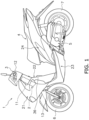
- FIG. 1 is a side view of a straddled vehicle 1 including a vehicle panel component 10 according to the preferred embodiment.
- the vehicle panel component according to the preferred embodiment has a decorative function; hence, the vehicle panel component is a vehicle decorative component.
- the straddled vehicle 1 includes a vehicle body frame 2, a steering device 3, a seat 4, a power unit 5, a front wheel 6, and a rear wheel 7.
- the vehicle body frame 2 includes a head pipe 11.
- the vehicle body frame 2 includes a down frame, a lower frame, and a rear frame, all of which are not illustrated in the drawings.
- the head pipe 11 is disposed in the middle of the vehicle in a vehicle width direction.
- the steering device 3 is supported by the head pipe 11 so as to be turnable.
- the steering device 3 includes a handle member 12 and a front fork 13.
- the handle member 12 is connected to the front fork 13.
- the front fork 13 is connected to the front wheel 6.
- the seat 4 is disposed directly behind the head pipe 11.
- the power unit 5 is disposed directly below the seat 4.
- the power unit 5 is supported by the vehicle body frame 2.
- the front wheel 6 is supported by the front fork 13 so as to be rotatable.
- the rear wheel 7 is rotated by a drive force generated by the power unit 5.
- the straddled vehicle 1 includes a front cover 21, a leg shield 22, a lower cover 23, and a rear cover 24.
- the front cover 21 covers the head pipe 11 from front.
- the leg shield 22 is disposed directly in front of the seat 4.
- the leg shield 22 covers the head pipe 11 from behind.
- the lower cover 23 is disposed between the leg shield 22 and the rear cover 24.
- the rear cover 24 is disposed directly below the seat 4.
- the straddled vehicle 1 includes a meter panel 30.
- the meter panel 30 is disposed in the middle of the vehicle in the vehicle width direction.
- the meter panel 30 is disposed on an upper portion of the handle member 12.
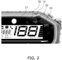
- the meter panel 30 includes a display face 31 and a panel face 32.
- the display face 31 displays vehicle speed and so forth on a liquid crystal screen.
- the panel face 32 is disposed on the circumferential edge of the display face 31.
- the panel face 32 may be integrated with the display face 31.
- the vehicle panel component 10 is provided as the meter panel 30.
- the vehicle panel component 10 includes the panel face 32.
- the panel face 32 of the meter panel 30 composes portion of the vehicle panel component 10.
- the panel face 32 is made of, for instance, a resin material.
- the panel face 32 is divided into a plurality of sections 33, each of which is made in shape of a polygon.
- the plural sections 33 are disposed in adjacent to each other.
- each of the plural sections 33 is made in shape of a triangle.
- each of the plural sections 33 is made in shape of an acute-angled triangle.
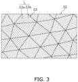
- FIG. 3 is a schematic plan view of portion of the panel face 32.
- each of the plural sections 33 includes a plurality of parallel lines L.
- the plural parallel lines L are disposed within each of the plural sections 33.
- the plural parallel lines L are provided on the surface of the panel face 32.
- the plural parallel lines L are formed by a plurality of recesses and protrusions.
- the plural parallel lines L are formed by alternately disposing a plurality of recesses 33a and a plurality of protrusions 33b.
- the plural recesses 33a and the plural protrusions 33b form a plurality of steps.
- the plural steps, formed by the plural recesses 33a and the plural protrusions 33b, are slight steps formed by, for instance, surface finishing such as painting.
- the plural recesses 33a are different in surface color from the plural protrusions 33b.
- the plural protrusions 33b have been processed by surface finishing.
- the plural protrusions 33b have been colored by painting. It should be noted that the plural recesses 33a may be colored by painting. In this case, the plural protrusions 33b are configured to further protrude from the surface of the panel face 32 than the plural recesses 33a.
- the plural parallel lines L extend straight.
- the plural parallel lines L are equal in width to each other at least when disposed within an identical section.
- the plural recesses 33a and the plural protrusions 33b are equal in width to each other.
- the plural protrusions 33b are drawn as being narrow in width for making the drawing clearly viewable.
- the plural parallel lines L are equal in width to each other in all the sections. It should be noted that the plural recesses 33a may be different in width from the plural protrusions 33b.
- Each of the plural parallel lines L may have a width dimension of greater than or equal to 0.2 mm and less than or equal to 0.4 mm. Each of the plural parallel lines L may have a width dimension of greater than or equal to 0.24 mm and less than or equal to 0.36 mm. Each of the plural parallel lines L may have a width dimension of greater than or equal to 0.27 mm and less than or equal to 0.33 mm. In the present preferred embodiment, each of the plural parallel lines L is set to have a width of 0.3 mm.
- a pattern of the plural parallel lines L is different between adjacent sections of the plural sections 33.
- an angle of the plural parallel lines L is different between the adjacent sections of the plural sections 33.
- the pattern of the plural parallel lines L is different between the adjacent sections of the plural sections 33 by such a positional arrangement that the plural recesses 33a and the plural protrusions 33b of the plural sections 33 are displaced from those in the adjacent sections of the plurality of sections 33.
- the plural parallel lines L may be disposed such that the plural recesses 33a and the plural protrusions 33b are not aligned straight with those in the adjacent sections of the plurality of sections 33.
- FIG. 4 is a closeup view of portion of FIG. 3 .
- the plural protrusions 33b are drawn as being narrow in width.
- the plural sections 33 are composed of a first section 41, a second section 42, a third section 43, and a fourth section 44.
- the second to fourth sections 42 to 44 are disposed in adjacent to the first section 41.
- the first section 41 includes a first side 41a, a second side 41b connected to the first side 41a, and a third side 41c connected to the first and second sides 41a and 41b.
- the first section 41 is formed by the first, second, and third sides 41a, 41b, and 41c.
- the first side 41a is a section line dividing the first and second sections 41 and 42.
- the second side 41b is a section line dividing the first and third sections 41 and 43.
- the third side 41c is a section line dividing the first and fourth sections 41 and 44.
- the first side 41a, the second side 41b, and the third side 41c may be referred to as a first section line 41a, a second section line 41b, and a third section line 41c, respectively, on an as-needed basis.
- the first, second, and third sides 41a, 41b, and 41c are different in dimension from each other.
- the dimension (D2) of the second side 41b is greater than the dimension (D1) of the first side 41a.
- the dimension (D3) of the third side 41c is greater than the dimension (D2) of the second side 41b.
- the dimension D1 of the first side 41a may be greater than or equal to 5 mm.
- the dimension D3 of the third side 41c may be greater than or equal to 7 mm and less than or equal to 9 mm.
- the dimension D1 of the first side 41a, the dimension D2 of the second side 41b, and the dimension D3 of the third side 41c are set to be 6 mm, 7 mm, and 8 mm, respectively.
- the first section 41 may have an area of greater than or equal to 18 mm 2 and less than or equal to 24 mm 2 .
- the area of the first section 41 is set to be 22.3 mm 2 .
- the first section 41 includes a plurality of first parallel lines L1.
- the plural first parallel lines L1 are disposed within the first section 41.
- the plural first parallel lines L1 extend straight.
- the plural first parallel lines L1 are formed by alternately disposing a plurality of recesses 41d and a plurality of protrusions 41e, both of which are provided on the surface of the first section 41.
- the recesses 41d are different in surface color from the protrusions 41e.
- the protrusions 41e are processed by surface finishing.
- the protrusions 41e are colored by painting. Accordingly, the recesses 41d and the protrusions 41e form a plurality of slight steps therebetween.
- the recesses 41d may be colored by painting.
- the protrusions 41e are configured to further protrude from the surface of the panel face 32 than the recesses 41d.
- the plural first parallel lines L1 are equal in width to each other.
- each recess 41d and each protrusion 41e are equal in width to each other.
- Each of the plural first parallel lines L1 may have a width dimension of greater than or equal to 0.2 mm and less than or equal to 0.4 mm.
- Each of the plural first parallel lines L1 may have a width dimension of greater than or equal to 0.24 mm and less than or equal to 0.36 mm.
- Each of the plural first parallel lines L1 may have a width dimension of greater than or equal to 0.27 mm and less than or equal to 0.33 mm.
- the width (W) of each of the plural first parallel lines L1 is set to be 0.3 mm. It should be noted that each recess 41d may be different in width from each protrusion 41e.
- the plural first parallel lines L1 extend to be directed to intersect with the first section line 41a.
- the plural first parallel lines L1 extend to be directed to intersect with the second section line 41b.
- the plural first parallel lines L1 extend to be directed to intersect with the third section line 41c.
- the plural first parallel lines L1 are different in extending direction from all the section lines 41a to 41c forming the first section 41.
- the second section 42 is disposed in adjacent to the first side 41a of the first section 41.
- the second section 42 includes a plurality of second parallel lines L2.
- the plural second parallel lines L2 are disposed within the second section 42.
- the plural second parallel lines L2 are formed by alternately disposing a plurality of recesses and a plurality of protrusions in a comparable manner to the plural first parallel lines L1.
- the plural second parallel lines L2 extend straight.
- the plural second parallel lines L2 are equal in width to each other.
- the width of each of the plural second parallel lines L2 is equal to the width W of each of the plural first parallel lines L1. It should be noted that the width of each of the plural second parallel lines L2 may be different from the width W of each of the plural first parallel lines L1.
- the plural second parallel lines L2 are different in pattern from the plural first parallel lines L1.
- the plural second parallel lines L2 are different in angle from the plural first parallel lines L1.
- the plural second parallel lines L2 extend to be directed to intersect with the plural first parallel lines L1.
- the plural second parallel lines L2 extend to be directed to intersect with the first section line 41a.
- the plural second parallel lines L2 are different in extending direction from all the section lines 41a, 42b, and 42c forming the second section 42.
- the third section 43 is disposed in adjacent to the second side 41b of the first section 41.
- the fourth section 44 is disposed in adjacent to the third side 41c of the first section 41. Not only the relation between the third section 43 and the first section 41 but also that between the fourth section 44 and the first section 41 is approximately identical to that between the second section 42 and the first section 41; hence, the third section 43 and the fourth section 44 will be hereinafter explained briefly.
- the third section 43 includes a plurality of third parallel lines L3.
- the plural third parallel lines L3 are different in pattern from the plural first parallel lines L1.
- the plural third parallel lines L3 are different in extending direction from all the section lines forming the third section 43.
- the fourth section 44 includes a plurality of fourth parallel lines L4.
- the plural fourth parallel lines L4 are different in pattern from the plural first parallel lines L1.
- the plural fourth parallel lines L4 are different in extending direction from all the section lines forming the fourth section 44.
- the panel face 32 of the vehicle panel component 10 is divided into the plural sections 33, each of which is made in shape of a polygon.
- the plural parallel lines L, disposed in each of the plural sections 33, are formed by a plurality of recesses and protrusions.
- One of each adjacent pair of the plural sections 33 is different in pattern of the plural parallel lines L from the other.
- a stereoscopic shape is formed by the plural steps formed by the plural recesses 33a and the plural protrusions 33b in each of the plural sections 33; hence, reflected light, entering the eyes of a rider, is changed in range and intensity.
- the reflected light stands out in relative movement between the eyes of the rider and the plural steps formed by the plural recesses 33a and the plural protrusions 33b.
- one of each adjacent pair of the plural sections 33 is different in pattern of the plural parallel lines L from the other; hence, the reflected light on one of each adjacent pair of the plural sections 33 appears to change in a different manner from that on the other.
- each adjacent pair of the plural sections 33 appears to change in different manners from each other in accordance with change in angle of reflection of external light or change in point of view of the rider; hence, such a visual effect as a lenticular image or hologram can be obtained on the panel face 32.
- enhancement in texture of the panel face 32 can be achieved with a simple configuration.
- each of the plural sections 33 is made in shape of a polygon; hence, further enhancement in texture of the panel face 32 can be achieved with a simple configuration.
- the panel face 32 is provided as the panel face of the meter panel 30; hence, the meter panel 30 is not only made eye-catching but also is enhanced in visibility.
- the teaching related to the straddled vehicle 1 is not limited to a scooter, and alternatively, may be another type of vehicle.
- the meter panel 30 may be disposed further on the front or rear side than the handle member 12.
- the display face 31 may be changed in configuration.
- the display face 31 may be made in form of an analog dial face.
- the vehicle panel component 10 may be disposed on another member viewable from the outside.
- the vehicle panel component 10 may be disposed on at least any one of the handle member 12, the front cover 21, the leg shield 22, the lower cover 23, and the rear cover 24.
- the vehicle panel component 10 may be disposed on a viewable member in another type of vehicle.
- Each of the plural sections 33 may be changed in shape and/or dimension.
- Each of the plural sections 33 may be made in shape of a quadrilateral or pentagon.
- At least one of the plural sections 33 may be made in shape of an obtuse-angled triangle, equilateral triangle, or isosceles triangle.
- the plural steps, formed by the plural recesses 33a and the plural protrusions 33b, may be formed with a different method from surface finishing such as painting.
Landscapes
- Engineering & Computer Science (AREA)
- Mechanical Engineering (AREA)
- Chemical & Material Sciences (AREA)
- Combustion & Propulsion (AREA)
- Transportation (AREA)
- Instrument Panels (AREA)
Abstract
Description
- The present invention relates to a vehicle panel component.
- It has been conventionally disclosed that a minute structure is provided on a panel face of a meter panel or so forth (see
JP 6153550 B2 - The panel face of the meter panel or so forth has a decorative function; hence, a vehicle panel component, having such a panel face, is desired to be enhanced in texture of the panel face thereof.
- It is an object of the present invention to provide a vehicle panel component that enhancement in texture of a panel face thereof can be achieved with a simple configuration. According to the present invention said object is solved by a vehicle panel component having the features of independent claim 1. Preferred embodiments are laid down in the dependent claims.
- A vehicle panel component according to an aspect includes a panel face. The panel face is divided into a plurality of sections. Each of the plurality of sections is made in shape of a polygon. The plurality of sections are disposed in adjacent to each other. The each of the plurality of sections includes a plurality of parallel lines disposed therewithin. The plurality of parallel lines are formed by a plurality of recesses and protrusions. A pattern of the plurality of parallel lines is different between adjacent sections of the plurality of sections.
- In the vehicle panel component according to the present aspect, the panel face is divided into the plurality of sections, each of which is made in shape of a polygon. The plurality of parallel lines, disposed in each of the plurality of sections, are formed by the plurality of recesses and protrusions. A pattern of the plurality of parallel lines is different between adjacent sections of the plurality of sections. In other words, a stereoscopic shape is formed by a plurality of steps formed by the plurality of recesses and protrusions in each of the plurality of sections; hence, reflected light, entering the eyes of a rider, is changed in range and intensity. Consequently, the reflected light stands out in relative movement between the eyes of the rider and the plurality of steps formed by the plurality of recesses and protrusions. Besides, the pattern of the plurality of parallel lines is different between adjacent sections of the plurality of sections; hence, the reflected light on the adjacent section of the plurality of sections appears to change in a different manner from each other. Accordingly, the adjacent section of the plurality of sections appears to change in different manners from each other in accordance with change in angle of reflection of external light or change in point of view of the rider; hence, such a visual effect as a lenticular image or hologram can be obtained on the panel face. As a result, enhancement in texture of the panel face can be achieved with a simple configuration. Besides, each of the plurality of sections is made in shape of a polygon; hence, further enhancement in texture of the panel face can be achieved with a simple configuration.
- An angle of the plurality of parallel lines is different between the adjacent sections of the plurality of sections. In this case, the adjacent sections of the plurality of sections can be made appear to change in different manners from each other in accordance with change in angle of reflection of external light or change in point of view of the rider with a simple configuration.
- The each of the plurality of sections may be made in shape of a triangle. In this case, it is made easy to recognize the shape of the each of the plurality of sections; hence, it is made easier to obtain such a visual effect as a lenticular image or hologram on the panel face.
- The each of the plurality of sections may be made in shape of an acute-angled triangle. In this case, it is made easy to recognize the shape of the each of the plurality of sections; hence, it is made easier to obtain such a visual effect as a lenticular image or hologram on the panel face.
- At least one of the plurality of sections may include a first side, a second side, and a third side. The second side is connected to the first side and has a dimension greater than a dimension of the first side. The third side is connected to the first side and the second side and has a dimension greater than the dimension of the second side. In this case, the panel face is made more eye-catching than a configuration that all the plurality of sections are made in shape of an equilateral triangle.
- The dimension of the first side may be greater than or equal to 5 mm. The dimension of the third side may be greater than or equal to 7 mm and less than or equal to 9 mm. In this case, it is made easier to obtain such a visual effect as a lenticular image or hologram on the panel face.
- At least one of the plurality of sections may have an area of greater than or equal to 18 mm2 and less than or equal to 24 mm2. In this case, it is made easier to obtain such a visual effect as a lenticular image or hologram on the panel face.
- The plurality of parallel lines may be equal in width to each other. In this case, it is made easy to recognize the plurality of sections; hence, it is made easier to obtain such a visual effect as a lenticular image or hologram on the panel face.
- Each of the plurality of parallel lines may have a width dimension of greater than or equal to 0.2 mm and less than or equal to 0.4 mm. Each of the plurality of parallel lines may have a width dimension of greater than or equal to 0.24 mm and less than or equal to 0.36 mm. Each of the plurality of parallel lines may have a width dimension of greater than or equal to 0.27 mm and less than or equal to 0.33 mm. In this case, it is made easy to recognize the plurality of sections in accordance with change in angle of reflection of external light or change in point of view of the rider; hence, it is made easier to obtain such a visual effect as a lenticular image or hologram on the panel face.
- The plurality of sections may include a first section and a second section. The second section is disposed in adjacent to the first section. The first section may include a plurality of first parallel lines disposed therewithin. The second section may include a plurality of second parallel lines disposed therewithin. The plurality of first parallel lines and the plurality of second parallel lines may extend to be directed to intersect with a section line dividing the first and second sections. In this case, it is made easy to recognize a boundary between the plurality of sections by the section line; hence, it is made easier to obtain such a visual effect as a lenticular image or hologram on the panel face.
- The plurality of first parallel lines may be different in extending direction from all section lines forming the first section. In this case, it is made easy to recognize the contour of the first section; hence, it is made easier to obtain such a visual effect as a lenticular image or hologram on the panel face.
- The panel face may be provided as a meter panel of the vehicle. In this case, the meter panel is not only made eye-catching but also is enhanced in visibility.
- The plurality recesses and protrusions may include a plurality of recesses and a plurality of protrusions. The plurality of recesses may be different in surface color from the plurality of protrusions. In this case, each adjacent pair of the plurality of sections can be made appear to change in different manners from each other responsively in accordance with change in angle of reflection of external light or change in point of view of the rider; hence, further enhancement in texture of the panel face can achieved.
- Overall, according to the present invention, it is made possible to provide a vehicle panel component that enhancement in texture of a panel face thereof can be achieved with a simple configuration.
-
-
FIG. 1 is a side view of a straddled vehicle including a vehicle panel component. -
FIG. 2 is a plan view of portion of a meter panel. -
FIG. 3 is a schematic plan view of portion of a panel face. -
FIG. 4 is a closeup view of portion ofFIG. 3 . -
FIG. 5 is a diagram for explaining a first section in detail. - A vehicle panel component according to a preferred embodiment will be hereinafter explained with reference to drawings.
FIG. 1 is a side view of a straddled vehicle 1 including avehicle panel component 10 according to the preferred embodiment. The vehicle panel component according to the preferred embodiment has a decorative function; hence, the vehicle panel component is a vehicle decorative component. - The straddled vehicle 1 includes a
vehicle body frame 2, asteering device 3, aseat 4, a power unit 5, afront wheel 6, and a rear wheel 7. - The
vehicle body frame 2 includes ahead pipe 11. Thevehicle body frame 2 includes a down frame, a lower frame, and a rear frame, all of which are not illustrated in the drawings. Thehead pipe 11 is disposed in the middle of the vehicle in a vehicle width direction. - The
steering device 3 is supported by thehead pipe 11 so as to be turnable. Thesteering device 3 includes ahandle member 12 and afront fork 13. Thehandle member 12 is connected to thefront fork 13. Thefront fork 13 is connected to thefront wheel 6. - The
seat 4 is disposed directly behind thehead pipe 11. The power unit 5 is disposed directly below theseat 4. The power unit 5 is supported by thevehicle body frame 2. Thefront wheel 6 is supported by thefront fork 13 so as to be rotatable. The rear wheel 7 is rotated by a drive force generated by the power unit 5. - The straddled vehicle 1 includes a
front cover 21, aleg shield 22, alower cover 23, and arear cover 24. Thefront cover 21 covers thehead pipe 11 from front. Theleg shield 22 is disposed directly in front of theseat 4. Theleg shield 22 covers thehead pipe 11 from behind. Thelower cover 23 is disposed between theleg shield 22 and therear cover 24. Therear cover 24 is disposed directly below theseat 4. - As shown in
FIG. 2 , the straddled vehicle 1 includes ameter panel 30. Themeter panel 30 is disposed in the middle of the vehicle in the vehicle width direction. Themeter panel 30 is disposed on an upper portion of thehandle member 12. - The
meter panel 30 includes a display face 31 and apanel face 32. The display face 31 displays vehicle speed and so forth on a liquid crystal screen. The panel face 32 is disposed on the circumferential edge of the display face 31. The panel face 32 may be integrated with the display face 31. - The
vehicle panel component 10 is provided as themeter panel 30. In the present preferred embodiment, thevehicle panel component 10 includes thepanel face 32. In other words, thepanel face 32 of themeter panel 30 composes portion of thevehicle panel component 10. The panel face 32 is made of, for instance, a resin material. - The panel face 32 is divided into a plurality of
sections 33, each of which is made in shape of a polygon. Theplural sections 33 are disposed in adjacent to each other. In the present preferred embodiment, each of theplural sections 33 is made in shape of a triangle. In more detail, each of theplural sections 33 is made in shape of an acute-angled triangle. -
FIG. 3 is a schematic plan view of portion of thepanel face 32. As shown inFIG. 3 , each of theplural sections 33 includes a plurality of parallel lines L. The plural parallel lines L are disposed within each of theplural sections 33. The plural parallel lines L are provided on the surface of thepanel face 32. The plural parallel lines L are formed by a plurality of recesses and protrusions. When described in detail, the plural parallel lines L are formed by alternately disposing a plurality ofrecesses 33a and a plurality ofprotrusions 33b. The plural recesses 33a and theplural protrusions 33b form a plurality of steps. The plural steps, formed by theplural recesses 33a and theplural protrusions 33b, are slight steps formed by, for instance, surface finishing such as painting. Theplural recesses 33a are different in surface color from theplural protrusions 33b. Theplural protrusions 33b have been processed by surface finishing. Theplural protrusions 33b have been colored by painting. It should be noted that theplural recesses 33a may be colored by painting. In this case, theplural protrusions 33b are configured to further protrude from the surface of thepanel face 32 than theplural recesses 33a. - The plural parallel lines L extend straight. The plural parallel lines L are equal in width to each other at least when disposed within an identical section. In other words, the
plural recesses 33a and theplural protrusions 33b are equal in width to each other. It should be noted that inFIG. 3 , theplural protrusions 33b are drawn as being narrow in width for making the drawing clearly viewable. In the present preferred embodiment, the plural parallel lines L are equal in width to each other in all the sections. It should be noted that theplural recesses 33a may be different in width from theplural protrusions 33b. - Each of the plural parallel lines L may have a width dimension of greater than or equal to 0.2 mm and less than or equal to 0.4 mm. Each of the plural parallel lines L may have a width dimension of greater than or equal to 0.24 mm and less than or equal to 0.36 mm. Each of the plural parallel lines L may have a width dimension of greater than or equal to 0.27 mm and less than or equal to 0.33 mm. In the present preferred embodiment, each of the plural parallel lines L is set to have a width of 0.3 mm.
- A pattern of the plural parallel lines L is different between adjacent sections of the
plural sections 33. For example, an angle of the plural parallel lines L is different between the adjacent sections of theplural sections 33.
When the angles of plural parallel lines L between the adjacent sections of theplural sections 33 are epual, the pattern of the plural parallel lines L is different between the adjacent sections of theplural sections 33 by such a positional arrangement that theplural recesses 33a and theplural protrusions 33b of theplural sections 33 are displaced from those in the adjacent sections of the plurality ofsections 33. In other words, the plural parallel lines L may be disposed such that theplural recesses 33a and theplural protrusions 33b are not aligned straight with those in the adjacent sections of the plurality ofsections 33. -
FIG. 4 is a closeup view of portion ofFIG. 3 . InFIG. 4 as well, theplural protrusions 33b are drawn as being narrow in width. As shown inFIG. 4 , theplural sections 33 are composed of afirst section 41, asecond section 42, athird section 43, and afourth section 44. The second tofourth sections 42 to 44 are disposed in adjacent to thefirst section 41. - The
first section 41 includes afirst side 41a, asecond side 41b connected to thefirst side 41a, and athird side 41c connected to the first andsecond sides first section 41 is formed by the first, second, andthird sides - The
first side 41a is a section line dividing the first andsecond sections second side 41b is a section line dividing the first andthird sections third side 41c is a section line dividing the first andfourth sections first side 41a, thesecond side 41b, and thethird side 41c may be referred to as afirst section line 41a, asecond section line 41b, and athird section line 41c, respectively, on an as-needed basis. - The first, second, and
third sides second side 41b is greater than the dimension (D1) of thefirst side 41a. The dimension (D3) of thethird side 41c is greater than the dimension (D2) of thesecond side 41b. - The dimension D1 of the
first side 41a may be greater than or equal to 5 mm. The dimension D3 of thethird side 41c may be greater than or equal to 7 mm and less than or equal to 9 mm. In the present preferred embodiment, the dimension D1 of thefirst side 41a, the dimension D2 of thesecond side 41b, and the dimension D3 of thethird side 41c are set to be 6 mm, 7 mm, and 8 mm, respectively. - The
first section 41 may have an area of greater than or equal to 18 mm2 and less than or equal to 24 mm2. In the present preferred embodiment, the area of thefirst section 41 is set to be 22.3 mm2. - The
first section 41 includes a plurality of first parallel lines L1. The plural first parallel lines L1 are disposed within thefirst section 41. The plural first parallel lines L1 extend straight. The plural first parallel lines L1 are formed by alternately disposing a plurality ofrecesses 41d and a plurality ofprotrusions 41e, both of which are provided on the surface of thefirst section 41. Therecesses 41d are different in surface color from theprotrusions 41e. Theprotrusions 41e are processed by surface finishing. Theprotrusions 41e are colored by painting. Accordingly, therecesses 41d and theprotrusions 41e form a plurality of slight steps therebetween. It should be noted that therecesses 41d may be colored by painting. In this case, theprotrusions 41e are configured to further protrude from the surface of thepanel face 32 than therecesses 41d. - The plural first parallel lines L1 are equal in width to each other. In other words, each
recess 41d and eachprotrusion 41e are equal in width to each other. Each of the plural first parallel lines L1 may have a width dimension of greater than or equal to 0.2 mm and less than or equal to 0.4 mm. Each of the plural first parallel lines L1 may have a width dimension of greater than or equal to 0.24 mm and less than or equal to 0.36 mm. Each of the plural first parallel lines L1 may have a width dimension of greater than or equal to 0.27 mm and less than or equal to 0.33 mm. In the present preferred embodiment, the width (W) of each of the plural first parallel lines L1 is set to be 0.3 mm. It should be noted that eachrecess 41d may be different in width from eachprotrusion 41e. - The plural first parallel lines L1 extend to be directed to intersect with the
first section line 41a. The plural first parallel lines L1 extend to be directed to intersect with thesecond section line 41b. The plural first parallel lines L1 extend to be directed to intersect with thethird section line 41c. In other words, the plural first parallel lines L1 are different in extending direction from all thesection lines 41a to 41c forming thefirst section 41. - As shown in
FIG. 4 , thesecond section 42 is disposed in adjacent to thefirst side 41a of thefirst section 41. Thesecond section 42 includes a plurality of second parallel lines L2. The plural second parallel lines L2 are disposed within thesecond section 42. The plural second parallel lines L2 are formed by alternately disposing a plurality of recesses and a plurality of protrusions in a comparable manner to the plural first parallel lines L1. The plural second parallel lines L2 extend straight. The plural second parallel lines L2 are equal in width to each other. The width of each of the plural second parallel lines L2 is equal to the width W of each of the plural first parallel lines L1. It should be noted that the width of each of the plural second parallel lines L2 may be different from the width W of each of the plural first parallel lines L1. - The plural second parallel lines L2 are different in pattern from the plural first parallel lines L1. When described in detail, the plural second parallel lines L2 are different in angle from the plural first parallel lines L1. In other words, the plural second parallel lines L2 extend to be directed to intersect with the plural first parallel lines L1. The plural second parallel lines L2 extend to be directed to intersect with the
first section line 41a. The plural second parallel lines L2 are different in extending direction from all thesection lines second section 42. - The
third section 43 is disposed in adjacent to thesecond side 41b of thefirst section 41. Thefourth section 44 is disposed in adjacent to thethird side 41c of thefirst section 41. Not only the relation between thethird section 43 and thefirst section 41 but also that between thefourth section 44 and thefirst section 41 is approximately identical to that between thesecond section 42 and thefirst section 41; hence, thethird section 43 and thefourth section 44 will be hereinafter explained briefly. - The
third section 43 includes a plurality of third parallel lines L3. The plural third parallel lines L3 are different in pattern from the plural first parallel lines L1. The plural third parallel lines L3 are different in extending direction from all the section lines forming thethird section 43. - The
fourth section 44 includes a plurality of fourth parallel lines L4. The plural fourth parallel lines L4 are different in pattern from the plural first parallel lines L1. The plural fourth parallel lines L4 are different in extending direction from all the section lines forming thefourth section 44. - In the straddled vehicle 1 according to the present aspect, the
panel face 32 of thevehicle panel component 10 is divided into theplural sections 33, each of which is made in shape of a polygon. The plural parallel lines L, disposed in each of theplural sections 33, are formed by a plurality of recesses and protrusions. One of each adjacent pair of theplural sections 33 is different in pattern of the plural parallel lines L from the other. In other words, a stereoscopic shape is formed by the plural steps formed by theplural recesses 33a and theplural protrusions 33b in each of theplural sections 33; hence, reflected light, entering the eyes of a rider, is changed in range and intensity. Consequently, the reflected light stands out in relative movement between the eyes of the rider and the plural steps formed by theplural recesses 33a and theplural protrusions 33b. Besides, one of each adjacent pair of theplural sections 33 is different in pattern of the plural parallel lines L from the other; hence, the reflected light on one of each adjacent pair of theplural sections 33 appears to change in a different manner from that on the other. - Accordingly, each adjacent pair of the
plural sections 33 appears to change in different manners from each other in accordance with change in angle of reflection of external light or change in point of view of the rider; hence, such a visual effect as a lenticular image or hologram can be obtained on thepanel face 32. As a result, enhancement in texture of thepanel face 32 can be achieved with a simple configuration. Besides, each of theplural sections 33 is made in shape of a polygon; hence, further enhancement in texture of thepanel face 32 can be achieved with a simple configuration. Furthermore, thepanel face 32 is provided as the panel face of themeter panel 30; hence, themeter panel 30 is not only made eye-catching but also is enhanced in visibility. - One preferred embodiment has been explained above. The teaching related to the straddled vehicle 1 is not limited to a scooter, and alternatively, may be another type of vehicle. The
meter panel 30 may be disposed further on the front or rear side than thehandle member 12. - The display face 31 may be changed in configuration. The display face 31 may be made in form of an analog dial face.
- The
vehicle panel component 10 may be disposed on another member viewable from the outside. For example, thevehicle panel component 10 may be disposed on at least any one of thehandle member 12, thefront cover 21, theleg shield 22, thelower cover 23, and therear cover 24. Thevehicle panel component 10 may be disposed on a viewable member in another type of vehicle. - Each of the
plural sections 33 may be changed in shape and/or dimension. Each of theplural sections 33 may be made in shape of a quadrilateral or pentagon. At least one of theplural sections 33 may be made in shape of an obtuse-angled triangle, equilateral triangle, or isosceles triangle. - The plural steps, formed by the
plural recesses 33a and theplural protrusions 33b, may be formed with a different method from surface finishing such as painting. -
- 10
- Vehicle panel component
- 32
- Panel face
- 33
- Plural sections
- 33a
- Plural recesses
- 33b
- Plural protrusions
- 41
- First section
- 41a
- First side
- 41b
- Second side
- 41c
- Third side
- 42
- Second section
- L
- Plural parallel lines
- L1
- Plural first parallel lines
- L2
- Plural second parallel lines
Claims (15)
- A vehicle panel component (10) comprising:a panel face (32) divided into a plurality of sections (33), each of the plurality of sections (33) made in shape of a polygon, the plurality of sections (33) disposed in adjacent to each other, whereinthe each of the plurality of sections (33) including a plurality of parallel lines disposed therewithin, the plurality of parallel lines (L) formed by a plurality of recesses (33a) and protrusions (33b), anda pattern of the plurality of parallel lines (L) is different between adjacent sections of the plurality of sections (33).
- The vehicle panel component (10) according to claim 1, wherein one of each adjacent pair of an angle of the plurality of parallel lines (L) is different between the adjacent sections of the plurality of sections (33).
- The vehicle panel component (10) according to claim 1 or 2, wherein the each of the plurality of sections (33) is made in shape of a triangle.
- The vehicle panel component (10) according to claim 1 or 2, wherein the each of the plurality of sections (33) is made in shape of an acute-angled triangle.
- The vehicle panel component (10) according to claim 3 or 4, wherein at least one of the plurality of sections (33) includes a first side (41a), a second side (41b), and a third side (41c), the second side (41b) connected to the first side (41a), the second side (41b) having a dimension greater than a dimension of the first side (41a), the third side (41c) connected to the first side (41a) and the second side (41b), the third side (41c) having a dimension greater than the dimension of the second side (41b).
- The vehicle panel component (10) according to claim 5, wherein the dimension of the first side (41a) is greater than or equal to 5 mm, and
the dimension of the third side (41c) is greater than or equal to 7 mm and less than or equal to 9 mm. - The vehicle panel component (10) according to any one of claims 1 to 6, wherein at least one of the plurality of sections (33) has an area of greater than or equal to 18 mm2 and less than or equal to 24 mm2.
- The vehicle panel component (10) according to any one of claims 1 to 7, wherein the plurality of parallel lines (L) are equal in width (W) to each other.
- The vehicle panel component (10) according to claim 8, wherein each of the plurality of parallel lines (L) has a width (W) dimension of greater than or equal to 0.2 mm and less than or equal to 0.4 mm.
- The vehicle panel component (10) according to claim 8, wherein each of the plurality of parallel lines (L) has a width (W) dimension of greater than or equal to 0.24 mm and less than or equal to 0.36 mm.
- The vehicle panel component (10) according to claim 8, wherein each of the plurality of parallel lines (L) has a width (W) dimension of greater than or equal to 0.27 mm and less than or equal to 0.33 mm.
- The vehicle panel component (10) according to any one of claims 1 to 11, wherein the plurality of sections (33) include a first section (41) and a second section (42), the second section (42) disposed in adjacent to the first section (41),the first section (41) includes a plurality of first parallel lines (L1) disposed therewithin, the second section (42) includes a plurality of second parallel lines (L2) disposed therewithin, andthe plurality of first parallel lines (L1) and the plurality of second parallel lines (L2) extend to be directed to intersect with a section line (41a) dividing the first and second sections (41, 42).
- The vehicle panel component (10) according to claim 12, wherein the plurality of first parallel lines (L1) are different in extending direction from all section lines (41a to 41c) forming the first section (41).
- The vehicle panel component (10) according to any one of claims 1 to 13, wherein the panel face (32) is provided as a meter panel (30) of the vehicle (1).
- The vehicle panel component (10) according to any one of claims 1 to 14, wherein the plurality of recesses (33a) and protrusions (33b) include a plurality of recesses (33a) and a plurality of protrusions (33b), and
the plurality of recesses (33a) are different in surface color from the plurality of protrusions (33b).
Applications Claiming Priority (1)
| Application Number | Priority Date | Filing Date | Title |
|---|---|---|---|
| JP2022172148A JP2024063944A (en) | 2022-10-27 | 2022-10-27 | Vehicle Decoration Parts |
Publications (2)
| Publication Number | Publication Date |
|---|---|
| EP4360931A1 true EP4360931A1 (en) | 2024-05-01 |
| EP4360931B1 EP4360931B1 (en) | 2025-01-01 |
Family
ID=87419214
Family Applications (1)
| Application Number | Title | Priority Date | Filing Date |
|---|---|---|---|
| EP23186038.8A Active EP4360931B1 (en) | 2022-10-27 | 2023-07-18 | Vehicle panel component |
Country Status (2)
| Country | Link |
|---|---|
| EP (1) | EP4360931B1 (en) |
| JP (1) | JP2024063944A (en) |
Citations (4)
| Publication number | Priority date | Publication date | Assignee | Title |
|---|---|---|---|---|
| US20050186396A1 (en) * | 2004-02-19 | 2005-08-25 | Toyoda Gosei Co., Ltd. | Extruded product |
| US20120052262A1 (en) * | 2009-05-07 | 2012-03-01 | Honda Motor Co., Ltd. | Vehicle upholstery member |
| JP6153550B2 (en) | 2014-02-03 | 2017-06-28 | ジョンソン コントロールズ オートモーティブ エレクトロニクス ゲーエムベーハー | Method for manufacturing a cover panel for at least one display instrument in a vehicle |
| EP3730333A1 (en) * | 2019-04-23 | 2020-10-28 | Bayerische Motoren Werke Aktiengesellschaft | Display assembly for vehicle |
-
2022
- 2022-10-27 JP JP2022172148A patent/JP2024063944A/en active Pending
-
2023
- 2023-07-18 EP EP23186038.8A patent/EP4360931B1/en active Active
Patent Citations (4)
| Publication number | Priority date | Publication date | Assignee | Title |
|---|---|---|---|---|
| US20050186396A1 (en) * | 2004-02-19 | 2005-08-25 | Toyoda Gosei Co., Ltd. | Extruded product |
| US20120052262A1 (en) * | 2009-05-07 | 2012-03-01 | Honda Motor Co., Ltd. | Vehicle upholstery member |
| JP6153550B2 (en) | 2014-02-03 | 2017-06-28 | ジョンソン コントロールズ オートモーティブ エレクトロニクス ゲーエムベーハー | Method for manufacturing a cover panel for at least one display instrument in a vehicle |
| EP3730333A1 (en) * | 2019-04-23 | 2020-10-28 | Bayerische Motoren Werke Aktiengesellschaft | Display assembly for vehicle |
Also Published As
| Publication number | Publication date |
|---|---|
| EP4360931B1 (en) | 2025-01-01 |
| JP2024063944A (en) | 2024-05-14 |
Similar Documents
| Publication | Publication Date | Title |
|---|---|---|
| JP4711007B2 (en) | Paralaskus barrier, autostereoscopic display | |
| US4999012A (en) | Display apparatus for a vehicle | |
| CN102472898A (en) | Parallax barrier for autostereoscopic display, autostereoscopic display, and method for designing parallax barrier for autostereoscopic display | |
| KR101945428B1 (en) | Substrate, grating and display panel | |
| DE102016209086B4 (en) | display device | |
| KR20030030365A (en) | Three dimensional image displaying apparatus | |
| CN102402011A (en) | Three-dimensional image display apparatus and image display device | |
| DE112018003715B4 (en) | VEHICLE DISPLAY DEVICE | |
| JP2001516899A (en) | Image display device by illusion of depth | |
| EP4360931B1 (en) | Vehicle panel component | |
| CN102123875B (en) | Ornamental display | |
| US6046710A (en) | Apparatus forming a border for an image | |
| JP5131599B2 (en) | Stereoscopic prints | |
| EP3680707B1 (en) | Display panel and preparation method therefor and display device thereof | |
| JP6304581B2 (en) | Blind spot assist device | |
| US12337610B2 (en) | Manufacturing of synthetic images with continuous animation | |
| JP6569097B2 (en) | Three-dimensional display formed body and method for producing the same | |
| JP4498629B2 (en) | Optical diffraction structure and manufacturing method thereof | |
| JP5635141B2 (en) | Decorative display | |
| JP2002012056A (en) | Instrument for vehicle | |
| AU2021402665A1 (en) | Methods for designing and producing a security feature | |
| CN119788832B (en) | Image three-dimensional method | |
| JPH0325490A (en) | Display device | |
| JP3009929U (en) | Lenticular printed matter | |
| JP3018898B2 (en) | Stereogram display |
Legal Events
| Date | Code | Title | Description |
|---|---|---|---|
| PUAI | Public reference made under article 153(3) epc to a published international application that has entered the european phase |
Free format text: ORIGINAL CODE: 0009012 |
|
| STAA | Information on the status of an ep patent application or granted ep patent |
Free format text: STATUS: REQUEST FOR EXAMINATION WAS MADE |
|
| 17P | Request for examination filed |
Effective date: 20230718 |
|
| AK | Designated contracting states |
Kind code of ref document: A1 Designated state(s): AL AT BE BG CH CY CZ DE DK EE ES FI FR GB GR HR HU IE IS IT LI LT LU LV MC ME MK MT NL NO PL PT RO RS SE SI SK SM TR |
|
| P01 | Opt-out of the competence of the unified patent court (upc) registered |
Free format text: CASE NUMBER: APP_37595/2024 Effective date: 20240624 |
|
| GRAP | Despatch of communication of intention to grant a patent |
Free format text: ORIGINAL CODE: EPIDOSNIGR1 |
|
| STAA | Information on the status of an ep patent application or granted ep patent |
Free format text: STATUS: GRANT OF PATENT IS INTENDED |
|
| RIC1 | Information provided on ipc code assigned before grant |
Ipc: B62J 50/22 20200101ALI20240823BHEP Ipc: B60K 35/40 20240101ALI20240823BHEP Ipc: B60K 35/215 20240101ALI20240823BHEP Ipc: B60K 37/20 20240101AFI20240823BHEP |
|
| INTG | Intention to grant announced |
Effective date: 20240910 |
|
| GRAS | Grant fee paid |
Free format text: ORIGINAL CODE: EPIDOSNIGR3 |
|
| GRAA | (expected) grant |
Free format text: ORIGINAL CODE: 0009210 |
|
| STAA | Information on the status of an ep patent application or granted ep patent |
Free format text: STATUS: THE PATENT HAS BEEN GRANTED |
|
| AK | Designated contracting states |
Kind code of ref document: B1 Designated state(s): AL AT BE BG CH CY CZ DE DK EE ES FI FR GB GR HR HU IE IS IT LI LT LU LV MC ME MK MT NL NO PL PT RO RS SE SI SK SM TR |
|
| REG | Reference to a national code |
Ref country code: GB Ref legal event code: FG4D |
|
| REG | Reference to a national code |
Ref country code: DE Ref legal event code: R096 Ref document number: 602023001576 Country of ref document: DE |
|
| REG | Reference to a national code |
Ref country code: CH Ref legal event code: EP |
|
| REG | Reference to a national code |
Ref country code: IE Ref legal event code: FG4D |
|
| REG | Reference to a national code |
Ref country code: LT Ref legal event code: MG9D |
|
| REG | Reference to a national code |
Ref country code: NL Ref legal event code: MP Effective date: 20250101 |
|
| REG | Reference to a national code |
Ref country code: AT Ref legal event code: MK05 Ref document number: 1755916 Country of ref document: AT Kind code of ref document: T Effective date: 20250101 |
|
| PG25 | Lapsed in a contracting state [announced via postgrant information from national office to epo] |
Ref country code: NL Free format text: LAPSE BECAUSE OF FAILURE TO SUBMIT A TRANSLATION OF THE DESCRIPTION OR TO PAY THE FEE WITHIN THE PRESCRIBED TIME-LIMIT Effective date: 20250101 |
|
| PG25 | Lapsed in a contracting state [announced via postgrant information from national office to epo] |
Ref country code: FI Free format text: LAPSE BECAUSE OF FAILURE TO SUBMIT A TRANSLATION OF THE DESCRIPTION OR TO PAY THE FEE WITHIN THE PRESCRIBED TIME-LIMIT Effective date: 20250101 |
|
| PG25 | Lapsed in a contracting state [announced via postgrant information from national office to epo] |
Ref country code: PL Free format text: LAPSE BECAUSE OF FAILURE TO SUBMIT A TRANSLATION OF THE DESCRIPTION OR TO PAY THE FEE WITHIN THE PRESCRIBED TIME-LIMIT Effective date: 20250101 |
|
| PG25 | Lapsed in a contracting state [announced via postgrant information from national office to epo] |
Ref country code: ES Free format text: LAPSE BECAUSE OF FAILURE TO SUBMIT A TRANSLATION OF THE DESCRIPTION OR TO PAY THE FEE WITHIN THE PRESCRIBED TIME-LIMIT Effective date: 20250101 |
|
| PG25 | Lapsed in a contracting state [announced via postgrant information from national office to epo] |
Ref country code: IS Free format text: LAPSE BECAUSE OF FAILURE TO SUBMIT A TRANSLATION OF THE DESCRIPTION OR TO PAY THE FEE WITHIN THE PRESCRIBED TIME-LIMIT Effective date: 20250501 Ref country code: NO Free format text: LAPSE BECAUSE OF FAILURE TO SUBMIT A TRANSLATION OF THE DESCRIPTION OR TO PAY THE FEE WITHIN THE PRESCRIBED TIME-LIMIT Effective date: 20250401 |
|
| PG25 | Lapsed in a contracting state [announced via postgrant information from national office to epo] |
Ref country code: HR Free format text: LAPSE BECAUSE OF FAILURE TO SUBMIT A TRANSLATION OF THE DESCRIPTION OR TO PAY THE FEE WITHIN THE PRESCRIBED TIME-LIMIT Effective date: 20250101 |
|
| PG25 | Lapsed in a contracting state [announced via postgrant information from national office to epo] |
Ref country code: LV Free format text: LAPSE BECAUSE OF FAILURE TO SUBMIT A TRANSLATION OF THE DESCRIPTION OR TO PAY THE FEE WITHIN THE PRESCRIBED TIME-LIMIT Effective date: 20250101 Ref country code: PT Free format text: LAPSE BECAUSE OF FAILURE TO SUBMIT A TRANSLATION OF THE DESCRIPTION OR TO PAY THE FEE WITHIN THE PRESCRIBED TIME-LIMIT Effective date: 20250502 |
|
| PG25 | Lapsed in a contracting state [announced via postgrant information from national office to epo] |
Ref country code: BG Free format text: LAPSE BECAUSE OF FAILURE TO SUBMIT A TRANSLATION OF THE DESCRIPTION OR TO PAY THE FEE WITHIN THE PRESCRIBED TIME-LIMIT Effective date: 20250101 Ref country code: GR Free format text: LAPSE BECAUSE OF FAILURE TO SUBMIT A TRANSLATION OF THE DESCRIPTION OR TO PAY THE FEE WITHIN THE PRESCRIBED TIME-LIMIT Effective date: 20250402 |
|
| PG25 | Lapsed in a contracting state [announced via postgrant information from national office to epo] |
Ref country code: AT Free format text: LAPSE BECAUSE OF FAILURE TO SUBMIT A TRANSLATION OF THE DESCRIPTION OR TO PAY THE FEE WITHIN THE PRESCRIBED TIME-LIMIT Effective date: 20250101 |
|
| PG25 | Lapsed in a contracting state [announced via postgrant information from national office to epo] |
Ref country code: CZ Free format text: LAPSE BECAUSE OF FAILURE TO SUBMIT A TRANSLATION OF THE DESCRIPTION OR TO PAY THE FEE WITHIN THE PRESCRIBED TIME-LIMIT Effective date: 20250101 |
|
| PG25 | Lapsed in a contracting state [announced via postgrant information from national office to epo] |
Ref country code: SE Free format text: LAPSE BECAUSE OF FAILURE TO SUBMIT A TRANSLATION OF THE DESCRIPTION OR TO PAY THE FEE WITHIN THE PRESCRIBED TIME-LIMIT Effective date: 20250101 |
|
| REG | Reference to a national code |
Ref country code: DE Ref legal event code: R097 Ref document number: 602023001576 Country of ref document: DE |
|
| PG25 | Lapsed in a contracting state [announced via postgrant information from national office to epo] |
Ref country code: SM Free format text: LAPSE BECAUSE OF FAILURE TO SUBMIT A TRANSLATION OF THE DESCRIPTION OR TO PAY THE FEE WITHIN THE PRESCRIBED TIME-LIMIT Effective date: 20250101 |
|
| PG25 | Lapsed in a contracting state [announced via postgrant information from national office to epo] |
Ref country code: DK Free format text: LAPSE BECAUSE OF FAILURE TO SUBMIT A TRANSLATION OF THE DESCRIPTION OR TO PAY THE FEE WITHIN THE PRESCRIBED TIME-LIMIT Effective date: 20250101 |
|
| PGFP | Annual fee paid to national office [announced via postgrant information from national office to epo] |
Ref country code: DE Payment date: 20250722 Year of fee payment: 3 |
|
| PGFP | Annual fee paid to national office [announced via postgrant information from national office to epo] |
Ref country code: IT Payment date: 20250731 Year of fee payment: 3 |
|
| PGFP | Annual fee paid to national office [announced via postgrant information from national office to epo] |
Ref country code: FR Payment date: 20250725 Year of fee payment: 3 |
|
| PG25 | Lapsed in a contracting state [announced via postgrant information from national office to epo] |
Ref country code: EE Free format text: LAPSE BECAUSE OF FAILURE TO SUBMIT A TRANSLATION OF THE DESCRIPTION OR TO PAY THE FEE WITHIN THE PRESCRIBED TIME-LIMIT Effective date: 20250101 |
|
| PG25 | Lapsed in a contracting state [announced via postgrant information from national office to epo] |
Ref country code: RO Free format text: LAPSE BECAUSE OF FAILURE TO SUBMIT A TRANSLATION OF THE DESCRIPTION OR TO PAY THE FEE WITHIN THE PRESCRIBED TIME-LIMIT Effective date: 20250101 |
|
| PG25 | Lapsed in a contracting state [announced via postgrant information from national office to epo] |
Ref country code: SK Free format text: LAPSE BECAUSE OF FAILURE TO SUBMIT A TRANSLATION OF THE DESCRIPTION OR TO PAY THE FEE WITHIN THE PRESCRIBED TIME-LIMIT Effective date: 20250101 |
|
| PLBE | No opposition filed within time limit |
Free format text: ORIGINAL CODE: 0009261 |
|
| STAA | Information on the status of an ep patent application or granted ep patent |
Free format text: STATUS: NO OPPOSITION FILED WITHIN TIME LIMIT |
|
| 26N | No opposition filed |
Effective date: 20251002 |
|
| PG25 | Lapsed in a contracting state [announced via postgrant information from national office to epo] |
Ref country code: LU Free format text: LAPSE BECAUSE OF NON-PAYMENT OF DUE FEES Effective date: 20250718 |
|
| REG | Reference to a national code |
Ref country code: BE Ref legal event code: MM Effective date: 20250731 |
|
| PG25 | Lapsed in a contracting state [announced via postgrant information from national office to epo] |
Ref country code: BE Free format text: LAPSE BECAUSE OF NON-PAYMENT OF DUE FEES Effective date: 20250731 |