EP4360458A1 - Platform for a trolley and rotary oven comprising such a platform - Google Patents
Platform for a trolley and rotary oven comprising such a platform Download PDFInfo
- Publication number
- EP4360458A1 EP4360458A1 EP22210342.6A EP22210342A EP4360458A1 EP 4360458 A1 EP4360458 A1 EP 4360458A1 EP 22210342 A EP22210342 A EP 22210342A EP 4360458 A1 EP4360458 A1 EP 4360458A1
- Authority
- EP
- European Patent Office
- Prior art keywords
- arm
- platform
- guide
- trolley
- cross member
- Prior art date
- Legal status (The legal status is an assumption and is not a legal conclusion. Google has not performed a legal analysis and makes no representation as to the accuracy of the status listed.)
- Granted
Links
Images

Classifications
-
- A—HUMAN NECESSITIES
- A21—BAKING; EDIBLE DOUGHS
- A21B—BAKERS' OVENS; MACHINES OR EQUIPMENT FOR BAKING
- A21B3/00—Parts or accessories of ovens
- A21B3/07—Charging or discharging ovens
-
- A—HUMAN NECESSITIES
- A21—BAKING; EDIBLE DOUGHS
- A21B—BAKERS' OVENS; MACHINES OR EQUIPMENT FOR BAKING
- A21B1/00—Bakers' ovens
- A21B1/42—Bakers' ovens characterised by the baking surfaces moving during the baking
- A21B1/44—Bakers' ovens characterised by the baking surfaces moving during the baking with surfaces rotating in a horizontal plane
Definitions
- the present invention relates to a platform for a trolley and a rotary oven comprising such a platform.
- the present invention is applied in particular to baking bread, pastry and similar products by means of hot air.
- convection ovens also known as fixed tray ovens
- the product is baked on baking trays by circulating hot air by means of fans, often with the presence of a system which generates the inversion of the rotation direction of the impeller, to improve the baking uniformity.
- the air is heated through electrical resistors or through a heat exchanger fed by a burner (typically "custom" burners).
- the product In rotary trolley ovens, the product is placed on baking trays which are in turn inserted in a trolley, usually in stainless steel, provided with wheels. The trolley is then placed in the oven and mounted on a rotation system which rotates it on itself by means of a motor for the entire duration of the baking.
- the oven bakes the product with hot air, where the air is circulated by means of fans and the air is heated through electrical resistors or through a heat exchanger fed by a burner (typically blown air burners).
- Rotary trolley ovens are used almost exclusively for baking bread, pastry and similar products since the rotation of the trolley offers a clear improvement in baking uniformity relative to the fixed tray convection ovens.
- the first solution includes a lifting hook inside the oven. It is a metal hook connected to the rotation motor.
- the hook has an inclined surface. When the trolley is pushed into the oven, it "rises” along the surface of the hook and detaches from the ground until it reaches a small hollow which prevents the trolley from sliding backwards. Once the trolley is in position, the hook begins to turn and the trolley therewith.
- the second solution includes a rotating platform placed inside the oven and connected to the rotation motor.
- the trolley is placed above the platform base, which is then rotated.
- the main drawback is related to the size and shape of the platform itself.
- the solutions currently on the market do not allow an adequate cleaning of the oven in the normal bread production cycles.
- residues remain below the platform base, which has the shape of a flat disc.
- Such a flat disc covers the bottom of the oven baking chamber, making the cleaning thereof difficult.
- Another drawback is related to the difficulty of adapting the platform to the multitude of trolleys available on the market.
- Each manufacturer uses different coupling systems, and over time several hybrid solutions have been created.
- the sale of new ovens is linked to the compatibility thereof with the trolleys already in the customers' possession.
- the technical task underlying the present invention is to propose a platform for a trolley and a rotary oven comprising such a platform which overcome the drawbacks of the cited prior art.
- Another object of the present invention is to provide a platform for a trolley, which is universal, i.e., easily employable for different trolley models.
- a platform for a trolley with wheels in particular insertable in an oven, said platform comprising a base for the trolley and a body mounted on the base, said body comprising a coupling portion for the trolley.
- the base comprises at least a first arm and a second arm respectively defining a first track and a second track for accommodating the wheels of the trolley.
- the base comprises at least one cross member connecting between the first arm and the second arm.
- the first arm and the second arm respectively extend prevalently along a first direction and a second direction that are parallel to each other.
- the first track and the second track are parallel to each other.
- the cross member extends prevalently along a third direction which is orthogonal to the first direction and to the second direction.
- the cross member extends between a central portion of the first arm and a central portion of the second arm.
- the cross member comprises a rest surface.
- the first arm and the second arm are mounted on the cross member at a greater height than the rest surface of the cross member.
- the platform further comprises a first guide and a second guide mounted on the base so as to guide the wheels of the trolley, respectively on the first arm and on the second arm.
- first guide and the second guide respectively extend in an elongated manner along the first arm and the second arm.
- the first guide is slidably mounted on the first arm so as to be able to translate transversely relative to the first direction and the second guide is slidably mounted on the second arm so as to be able to translate transversely relative to the second direction.
- the platform comprises a coupling means between the first guide and the second guide.
- the coupling means comprises a telescopic device having a first end to which the first guide is fixed and a second end to which the second guide is fixed.
- the platform comprises an elastic means interposed between the first and the second arm.
- a rotary oven comprising:
- reference numeral 1 indicates a platform for a trolley 100 provided with wheels.
- the platform 1 comprises a base 2 for the trolley 100 and a body 15 mounted on the base 2.
- the base 2 comprises at least a first arm 3, a second arm 4 and a cross member 5 connecting between the first arm 3 and the second arm 4.
- the first arm 3 defines a first track and the second arm 4 defines a second track for accommodating the wheels of the trolley 100.
- the first arm 3 has an elongated extension along a first direction A
- the second arm 4 has an elongated extension along a second direction B.
- the first direction A and the second direction B are substantially parallel.
- the first track and the second track are likewise preferably parallel to each other.
- the first arm 3 extends along the first direction A between a first end 3a and a second end 3b.
- the second arm 4 extends along the second direction B between a first end 4a and a second end 4b.
- the cross member 5 extends in an elongated manner along a third direction C which is orthogonal to the first direction A and to the second direction B.
- the cross member 5 extends between a central portion of the first arm 3 and a central portion of the second arm 4.
- the cross member 5 is arranged substantially halfway between the first arm 3 and the second arm 4.
- the base 2 substantially has an "H" shape.
- the two arms 3, 4 constitute the long sides of the "H", while the cross member 5 constitutes the short side of the "H”.
- the cross member 5 is inclined relative to the two arms 3, 4 forming an angle different from 90°.
- the cross member 5 is arranged diagonally relative to the two arms 3,4.
- the cross member 5 has a rest surface (not visible in the figures), intended to be rested on the bottom of a baking chamber 202 of an oven 200.
- the first arm 3 and the second arm 4 are mounted on the cross member 5 at a greater height than the rest surface of the cross member 5. Thereby, the first arm 3 and the second arm 4 do not rest on the bottom of the baking chamber 202 of the oven 200, but are raised relative thereto.
- the cross member 5 is the only part of the platform 2 which rests on the bottom of the baking chamber 202 of the oven 200.
- the cross member 5 comprises one or more bearings (not illustrated).
- the cross member 5 comprises a greasing system (not illustrated).
- the greasing system is of the automatic type.
- the greasing system is of the manual type.
- the platform 1 comprises a first guide 6 and a second guide 7 mounted on the base 2 so as to be positioned respectively at the first arm 3 and the second arm 4.
- the first guide 6 extends elongated along the first arm 3.
- the first guide 6 extends elongated along at least partially according to a direction substantially parallel to the first direction A.
- the second guide 7 extends elongated along the second arm 4.
- the second guide 7 extends elongated at least partially according to a direction substantially parallel to the second direction B.
- the first guide 6 is slidably mounted on the first arm 3 so as to be able to translate transversely relative to the first direction A and the second guide 7 is slidably mounted on the second arm 4 so as to be able to translate transversely relative to the second direction B.
- the first guide 6 is slidably mounted on the first arm 3 so as to be able to translate orthogonally relative to the first direction A and the second guide 7 is slidably mounted on the second arm 4 so as to be able to translate orthogonally relative to the second direction B.
- the first guide 6 and the second guide 7 are preferably coupled, i.e., joined, by a coupling means 8.
- the coupling means 8 comprises a telescopic device (always indicated with 8) having a first end 9 to which the first guide 6 is fixed and a second end 11 to which the second guide 7 is fixed.
- first guide 6 and the second guide 7 are fixed to the cross member 5.
- the telescopic device 8 comprises two perforated end portions 10, 12 of the cross member 5: a first perforated end portion 10 and a second perforated end portion 12, which are located on opposite sides of the cross member 5.
- the first end 9 and the second end 11 of the telescopic device 8 are slidably mounted relative to the perforated end portions 10, 12 of the cross member 5.
- the first end 9 is slidably mounted within a first perforated end portion 10 so as to elongate telescopically in a direction transverse to the first arm 3 and move the first guide 6.
- the second end 11 is slidably mounted within a second perforated end portion 12 so as to elongate telescopically in a direction transverse to the second arm 4 and move the second guide 7.
- the first guide 6 is movable (i.e., sliding) between a first position and a second position relative to the first arm 3. In at least one intermediate position between the first and the second position, the first guide 6 is located above and facing relative to the first arm 3.
- the second guide 7 is movable (i.e., sliding) between a first position and a second position relative to the second arm 4. In at least one intermediate position between the first and the second position, the second guide 7 is located above and facing relative to the second arm 4.
- the mobility of the two guides 6, 7 allows the position thereof to be adjusted as a function of the width of the trolley. Thereby, different trolleys can be accommodated by the same platform.
- the first arm 3 comprises a first support surface 13 intended to support a pair of wheels of the trolley.
- the second arm 4 comprises a second support surface 14 intended to support the other pair of wheels of the trolley.
- the first support surface 13 has a substantially planar extension defined by a length (i.e., dimension along the first direction A) and by a width (i.e., dimension along a direction orthogonal to the first direction A).
- the first track is defined and comprised in the first support surface 13.
- the second support surface 14 has a substantially planar extension defined by a length (i.e., dimension along the second direction B) and a width (i.e., dimension along a direction orthogonal to the second direction B).
- the second track is defined and comprised in the second support surface 14.
- the sliding direction of the first end 9 of the telescopic device 8 is substantially parallel to the width of the first support surface 13.
- the sliding direction of the second end 11 of the telescopic device 8 is substantially parallel to the width of the second support surface 14.
- the position of the two guides 6, 7 is adjustable relative to the width of the respective arm 3, 4.
- first end 3a of the first arm 3 and the first end 4a of the second arm 4 are curved towards the inside of the base 2. That is, such first ends 3a, 4a are converging.
- the first guide 6 comprises a first curved section 6a arranged at the first end 3a of the first arm 3 and a first straight section 6b.
- the second guide 7 comprises a second curved section 7a arranged at the first end 4a of the second arm 4 and a second straight section 7b.
- the body 15 comprises at least one upright (illustrated with the same number 15) extending away from the base 2 between a first end 15a and a second end 15b.
- the first end 15a of the upright 15 originates laterally from the base 2.
- the second end 15b is raised relative to the base 2 and thus at the first end 15a.
- the upright 15 comprises a coupling portion 16 intended to couple with a driving means 203 of a rotary oven 200.
- the coupling portion 16 comprises a through opening 17 for coupling with such a driving means 203.
- the first ends 15a of the two uprights 15 originate from the outer sides of the first and the second arm 3, 4, respectively.
- the second ends 15b of the two uprights 15 are approached above the base 2.
- the second ends 15b are joined together. That is, the two uprights 15 have arched extension above the base 2.
- the coupling portion 16 is shared between the two uprights 15 and acts as a joining section between the two second ends 15b.
- the platform 1 comprises an elastic means 18 interposed between the first and the second arm 3, 4.
- the elastic means 18 is connected to the second ends 3b, 4b of the first and the second arm 3, 4.
- the elastic means 18 comprises at least one spring in harmonic material.
- the base 2 comprises two arms 3, 4 and a plurality of cross members 5.
- the cross members 5 are parallel to each other and are arranged orthogonally to the arms 3, 4.
- the base 2 comprises two arms 3, 4 and two cross members 5 constituting sides of a rectangle or a square, i.e., the base 2 has a closed shape.
- a rotary oven indicated with the number 200 and described below, is further an object of the present invention.
- the rotary oven 200 comprises a box-like casing 201 internally defining a baking chamber 202.
- the rotary oven 200 comprises a driving means 203 operatively active on the platform 1 to rotate it around a predefined rotation axis D-D, preferably vertical.
- the driving means 203 is coupled with the coupling portion 16 of the upright 15.
- the driving means 203 comprises a pin 205 and a motorised means 204 operatively connected to the pin 205 to rotate it around a longitudinal axis thereof.
- the coupling portion 16 is coupled with the pin 205 by means of the through opening 17.
- the upright 15 receives the rotation from the pin 205 and transmits it to the base 2.
- the rotation of the base 2 involves the rotation of the trolley 100 which lies above it.
- the rotary oven 200 comprises a heating means (not illustrated) of a baking fluid.
- the rotary oven 200 comprises a means for recirculating (not shown) the baking fluid from the baking chamber 202 to the heating means, and vice versa.
- the baking fluid is air.
- the rotary oven 200 comprises a ramp 206 placed in front of the base 2 of the platform 1 to facilitate the positioning of the trolley on the base 2.
- the shape proposed for the base of the platform allows to significantly reduce the overall dimensions of the platform in the baking chamber, allowing an easier and more reliable cleaning of the bottom of the chamber.
- the platform proposed here allows to have a base with a footprint smaller by 60 ⁇ 70%, depending on the size of the oven.
- adjustable guides allows to use the same platform for different types of trolleys.
- the guides which are adjustable according to the width of the arms allow extreme versatility, avoiding guide format changes.
Landscapes
- Life Sciences & Earth Sciences (AREA)
- Engineering & Computer Science (AREA)
- Food Science & Technology (AREA)
- Baking, Grill, Roasting (AREA)
- Handcart (AREA)
Abstract
- at least a first arm (3) and a second arm (4) respectively defining a first track and a second track for accommodating the wheels of the trolley (100);
- at least one cross member (5) connecting between the first arm (3) and the second arm (4).
Description
- The present invention relates to a platform for a trolley and a rotary oven comprising such a platform.
- The present invention is applied in particular to baking bread, pastry and similar products by means of hot air.
- As is known, baking bread, pastry and similar products by means of hot air occurs using two technologies: convection ovens and rotary trolley ovens. In convection ovens (otherwise known as fixed tray ovens), the product is baked on baking trays by circulating hot air by means of fans, often with the presence of a system which generates the inversion of the rotation direction of the impeller, to improve the baking uniformity. The air is heated through electrical resistors or through a heat exchanger fed by a burner (typically "custom" burners).
- Fixed baking ovens have been greatly developed in the world of gastronomy, but have had a limited impact in the world of baking bread, pastry and similar products. This is due to the fact that such products require as uniform baking as possible, which the fixed tray ovens cannot ensure.
- In rotary trolley ovens, the product is placed on baking trays which are in turn inserted in a trolley, usually in stainless steel, provided with wheels. The trolley is then placed in the oven and mounted on a rotation system which rotates it on itself by means of a motor for the entire duration of the baking.
- The oven bakes the product with hot air, where the air is circulated by means of fans and the air is heated through electrical resistors or through a heat exchanger fed by a burner (typically blown air burners).
- Rotary trolley ovens are used almost exclusively for baking bread, pastry and similar products since the rotation of the trolley offers a clear improvement in baking uniformity relative to the fixed tray convection ovens.
- Currently, two alternative solutions are used for the rotation of the trolley.
- The first solution includes a lifting hook inside the oven. It is a metal hook connected to the rotation motor. The hook has an inclined surface. When the trolley is pushed into the oven, it "rises" along the surface of the hook and detaches from the ground until it reaches a small hollow which prevents the trolley from sliding backwards. Once the trolley is in position, the hook begins to turn and the trolley therewith.
- The second solution includes a rotating platform placed inside the oven and connected to the rotation motor. The trolley is placed above the platform base, which is then rotated.
- In the context of rotary ovens with rotating platform, the main drawback is related to the size and shape of the platform itself. The solutions currently on the market do not allow an adequate cleaning of the oven in the normal bread production cycles. In particular, residues remain below the platform base, which has the shape of a flat disc. Such a flat disc covers the bottom of the oven baking chamber, making the cleaning thereof difficult. Another drawback is related to the difficulty of adapting the platform to the multitude of trolleys available on the market. Each manufacturer uses different coupling systems, and over time several hybrid solutions have been created. In fact, in a market strongly oriented to replacement, the sale of new ovens is linked to the compatibility thereof with the trolleys already in the customers' possession.
- In this context, the technical task underlying the present invention is to propose a platform for a trolley and a rotary oven comprising such a platform which overcome the drawbacks of the cited prior art.
- In particular, it is an object of the present invention to propose a platform for a trolley and a rotary oven comprising such a platform, which allow a better cleaning relative to the known solutions.
- Another object of the present invention is to provide a platform for a trolley, which is universal, i.e., easily employable for different trolley models.
- The technical aims listed above are substantially achieved by a platform for a trolley with wheels, in particular insertable in an oven, said platform comprising a base for the trolley and a body mounted on the base, said body comprising a coupling portion for the trolley. The base comprises at least a first arm and a second arm respectively defining a first track and a second track for accommodating the wheels of the trolley. The base comprises at least one cross member connecting between the first arm and the second arm.
- In accordance with an embodiment, the first arm and the second arm respectively extend prevalently along a first direction and a second direction that are parallel to each other.
- In accordance with an embodiment, the first track and the second track are parallel to each other.
- In accordance with an embodiment, the cross member extends prevalently along a third direction which is orthogonal to the first direction and to the second direction.
- In accordance with an embodiment, the cross member extends between a central portion of the first arm and a central portion of the second arm.
- In accordance with an embodiment, the cross member comprises a rest surface. In accordance with an embodiment, the first arm and the second arm are mounted on the cross member at a greater height than the rest surface of the cross member.
- In accordance with an embodiment, the platform further comprises a first guide and a second guide mounted on the base so as to guide the wheels of the trolley, respectively on the first arm and on the second arm.
- In accordance with an embodiment, the first guide and the second guide respectively extend in an elongated manner along the first arm and the second arm.
- In accordance with an embodiment, the first guide is slidably mounted on the first arm so as to be able to translate transversely relative to the first direction and the second guide is slidably mounted on the second arm so as to be able to translate transversely relative to the second direction.
- In accordance with an embodiment, the platform comprises a coupling means between the first guide and the second guide.
- Preferably, the coupling means comprises a telescopic device having a first end to which the first guide is fixed and a second end to which the second guide is fixed.
- In accordance with an embodiment, the platform comprises an elastic means interposed between the first and the second arm.
- The technical aims listed above are substantially achieved by a rotary oven, comprising:
- a box-like casing internally defining a baking chamber;
- a platform according to what has been described, said platform being positioned inside the baking chamber;
- a driving means configured to rotate said platform around a predefined rotation axis.
- Further features and advantages of the present invention will become more apparent from the indicative and thus non-limiting description of a preferred, but not exclusive, embodiment of a platform for a trolley and a rotary oven comprising such a platform, as illustrated in the appended drawings, in which:
-
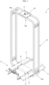
figure 1 illustrates a platform for a trolley, object of the present invention, in perspective view from behind; -
figures 2 and 3 illustrate a top view of a detail (base) of the platform offigure 1 , in which the guides are respectively positioned in two different configurations; -
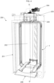
figure 4 illustrates a rotary oven, subject-matter of the present invention, in perspective view; -
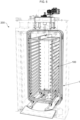
figure 5 illustrates the rotary oven offigure 4 , in which a trolley has been inserted. - With reference to the figures,
reference numeral 1 indicates a platform for atrolley 100 provided with wheels. - The
platform 1 comprises abase 2 for thetrolley 100 and abody 15 mounted on thebase 2. - Originally, the
base 2 comprises at least a first arm 3, asecond arm 4 and across member 5 connecting between the first arm 3 and thesecond arm 4. - The first arm 3 defines a first track and the
second arm 4 defines a second track for accommodating the wheels of thetrolley 100. - In accordance with the embodiment described and shown herein, the first arm 3 has an elongated extension along a first direction A, while the
second arm 4 has an elongated extension along a second direction B. In the embodiment illustrated in the figures, the first direction A and the second direction B are substantially parallel. - The first track and the second track are likewise preferably parallel to each other.
- Preferably, the first arm 3 extends along the first direction A between a
first end 3a and asecond end 3b. - Preferably, the
second arm 4 extends along the second direction B between afirst end 4a and asecond end 4b. - Preferably, the
cross member 5 extends in an elongated manner along a third direction C which is orthogonal to the first direction A and to the second direction B. - Preferably, the
cross member 5 extends between a central portion of the first arm 3 and a central portion of thesecond arm 4. - In particular, the
cross member 5 is arranged substantially halfway between the first arm 3 and thesecond arm 4. In such a case, thebase 2 substantially has an "H" shape. In particular, the twoarms 3, 4 constitute the long sides of the "H", while thecross member 5 constitutes the short side of the "H". - In accordance with an alternative embodiment, not illustrated, the
cross member 5 is inclined relative to the twoarms 3, 4 forming an angle different from 90°. For example, thecross member 5 is arranged diagonally relative to the twoarms 3,4. - The
cross member 5 has a rest surface (not visible in the figures), intended to be rested on the bottom of abaking chamber 202 of anoven 200. - Preferably, the first arm 3 and the
second arm 4 are mounted on thecross member 5 at a greater height than the rest surface of thecross member 5. Thereby, the first arm 3 and thesecond arm 4 do not rest on the bottom of thebaking chamber 202 of theoven 200, but are raised relative thereto. Preferably, thecross member 5 is the only part of theplatform 2 which rests on the bottom of thebaking chamber 202 of theoven 200. - Preferably, the
cross member 5 comprises one or more bearings (not illustrated). - Preferably, the
cross member 5 comprises a greasing system (not illustrated). In an embodiment, the greasing system is of the automatic type. In an alternative embodiment, the greasing system is of the manual type. - The
platform 1 comprises afirst guide 6 and asecond guide 7 mounted on thebase 2 so as to be positioned respectively at the first arm 3 and thesecond arm 4. - Preferably, the
first guide 6 extends elongated along the first arm 3. Preferably, thefirst guide 6 extends elongated along at least partially according to a direction substantially parallel to the first direction A. Preferably, thesecond guide 7 extends elongated along thesecond arm 4. Preferably, thesecond guide 7 extends elongated at least partially according to a direction substantially parallel to the second direction B. - In accordance with an aspect of the invention, the
first guide 6 is slidably mounted on the first arm 3 so as to be able to translate transversely relative to the first direction A and thesecond guide 7 is slidably mounted on thesecond arm 4 so as to be able to translate transversely relative to the second direction B. - Preferably, the
first guide 6 is slidably mounted on the first arm 3 so as to be able to translate orthogonally relative to the first direction A and thesecond guide 7 is slidably mounted on thesecond arm 4 so as to be able to translate orthogonally relative to the second direction B. - The
first guide 6 and thesecond guide 7 are preferably coupled, i.e., joined, by a coupling means 8. - In accordance with an embodiment described and illustrated herein, the coupling means 8 comprises a telescopic device (always indicated with 8) having a
first end 9 to which thefirst guide 6 is fixed and asecond end 11 to which thesecond guide 7 is fixed. - In the preferred embodiment, the
first guide 6 and thesecond guide 7 are fixed to thecross member 5. - Preferably, the
telescopic device 8 comprises twoperforated end portions perforated end portion 10 and a secondperforated end portion 12, which are located on opposite sides of thecross member 5. - The
first end 9 and thesecond end 11 of thetelescopic device 8 are slidably mounted relative to theperforated end portions cross member 5. - The
first end 9 is slidably mounted within a firstperforated end portion 10 so as to elongate telescopically in a direction transverse to the first arm 3 and move thefirst guide 6. - The
second end 11 is slidably mounted within a secondperforated end portion 12 so as to elongate telescopically in a direction transverse to thesecond arm 4 and move thesecond guide 7. - Preferably, the
first guide 6 is movable (i.e., sliding) between a first position and a second position relative to the first arm 3. In at least one intermediate position between the first and the second position, thefirst guide 6 is located above and facing relative to the first arm 3. - Preferably, the
second guide 7 is movable (i.e., sliding) between a first position and a second position relative to thesecond arm 4. In at least one intermediate position between the first and the second position, thesecond guide 7 is located above and facing relative to thesecond arm 4. - The mobility of the two
guides - In particular, the first arm 3 comprises a
first support surface 13 intended to support a pair of wheels of the trolley. Thesecond arm 4 comprises asecond support surface 14 intended to support the other pair of wheels of the trolley. - The
first support surface 13 has a substantially planar extension defined by a length (i.e., dimension along the first direction A) and by a width (i.e., dimension along a direction orthogonal to the first direction A). - In practice, the first track is defined and comprised in the
first support surface 13. - The
second support surface 14 has a substantially planar extension defined by a length (i.e., dimension along the second direction B) and a width (i.e., dimension along a direction orthogonal to the second direction B). - In practice, the second track is defined and comprised in the
second support surface 14. - The sliding direction of the
first end 9 of thetelescopic device 8 is substantially parallel to the width of thefirst support surface 13. - The sliding direction of the
second end 11 of thetelescopic device 8 is substantially parallel to the width of thesecond support surface 14. - That is, the position of the two
guides respective arm 3, 4. - In the preferred embodiment, the
first end 3a of the first arm 3 and thefirst end 4a of thesecond arm 4 are curved towards the inside of thebase 2. That is, suchfirst ends - Similarly, the
first guide 6 comprises a firstcurved section 6a arranged at thefirst end 3a of the first arm 3 and a firststraight section 6b. - The
second guide 7 comprises a secondcurved section 7a arranged at thefirst end 4a of thesecond arm 4 and a secondstraight section 7b. - The
body 15 comprises at least one upright (illustrated with the same number 15) extending away from thebase 2 between afirst end 15a and asecond end 15b. Thefirst end 15a of theupright 15 originates laterally from thebase 2. Thesecond end 15b is raised relative to thebase 2 and thus at thefirst end 15a. - Preferably, the
upright 15 comprises acoupling portion 16 intended to couple with a driving means 203 of arotary oven 200. Preferably, thecoupling portion 16 comprises a throughopening 17 for coupling with such a driving means 203. - In the preferred embodiment, there are two
uprights 15 which originate from two opposite sides of thebase 2. Preferably, the first ends 15a of the twouprights 15 originate from the outer sides of the first and thesecond arm 3, 4, respectively. - Preferably, the second ends 15b of the two
uprights 15 are approached above thebase 2. Preferably, the second ends 15b are joined together. That is, the twouprights 15 have arched extension above thebase 2. In this case, thecoupling portion 16 is shared between the twouprights 15 and acts as a joining section between the twosecond ends 15b. - Preferably, the
platform 1 comprises anelastic means 18 interposed between the first and thesecond arm 3, 4. - Preferably, the elastic means 18 is connected to the second ends 3b, 4b of the first and the
second arm 3, 4. - Preferably, the elastic means 18 comprises at least one spring in harmonic material.
- In an alternative embodiment, the
base 2 comprises twoarms 3, 4 and a plurality ofcross members 5. For example, thecross members 5 are parallel to each other and are arranged orthogonally to thearms 3, 4. - In a variant, there are two
cross members 5 arranged to form an "X" connecting thearms 3, 4. - In an alternative embodiment, the
base 2 comprises twoarms 3, 4 and twocross members 5 constituting sides of a rectangle or a square, i.e., thebase 2 has a closed shape. - A rotary oven, indicated with the
number 200 and described below, is further an object of the present invention. - The
rotary oven 200 comprises a box-like casing 201 internally defining abaking chamber 202. - The
rotary oven 200 comprises a driving means 203 operatively active on theplatform 1 to rotate it around a predefined rotation axis D-D, preferably vertical. - In particular, the driving means 203 is coupled with the
coupling portion 16 of theupright 15. - Preferably, the driving means 203 comprises a
pin 205 and a motorised means 204 operatively connected to thepin 205 to rotate it around a longitudinal axis thereof. - The
coupling portion 16 is coupled with thepin 205 by means of the throughopening 17. Theupright 15 receives the rotation from thepin 205 and transmits it to thebase 2. The rotation of thebase 2 involves the rotation of thetrolley 100 which lies above it. - The
rotary oven 200 comprises a heating means (not illustrated) of a baking fluid. - The
rotary oven 200 comprises a means for recirculating (not shown) the baking fluid from thebaking chamber 202 to the heating means, and vice versa. - Preferably, the baking fluid is air.
- Preferably, the
rotary oven 200 comprises aramp 206 placed in front of thebase 2 of theplatform 1 to facilitate the positioning of the trolley on thebase 2. - The features of the platform for a trolley and the rotary oven comprising such a platform emerge clearly from the above description, as do the advantages.
- In particular, the shape proposed for the base of the platform (two arms joined transversely by the cross member) allows to significantly reduce the overall dimensions of the platform in the baking chamber, allowing an easier and more reliable cleaning of the bottom of the chamber.
- Relative to a traditional platform, the platform proposed here allows to have a base with a footprint smaller by 60÷70%, depending on the size of the oven.
- Furthermore, the presence of adjustable guides allows to use the same platform for different types of trolleys. In fact, the guides which are adjustable according to the width of the arms allow extreme versatility, avoiding guide format changes.
Claims (12)
- A platform (1) for a trolley (100) with wheels, in particular insertable in an oven (200), said platform (1) comprising a base (2) for the trolley (100) and a body (15) mounted on the base (2), said body (15) comprising a coupling portion (16) for the trolley (100),
characterised in that said base (2) comprises:- at least a first arm (3) and a second arm (4) respectively defining a first track and a second track for accommodating the wheels of the trolley (100);- at least one cross member (5) connecting between the first arm (3) and the second arm (4). - The platform (1) according to claim 1, wherein the first arm (3) and the second arm (4) respectively extend prevalently along a first direction (A) and a second direction (B) that are parallel to each other, said first track and said second track likewise being parallel to each other.
- The platform (1) according to claim 2, wherein the cross member (5) extends prevalently along a third direction (C) which is orthogonal to the first direction (A) and to the second direction (B).
- The platform (1) according to any one of the preceding claims, wherein the cross member (5) extends between a central portion of the first arm (3) and a central portion of the second arm (4).
- The platform (1) according to any one of the preceding claims, wherein said cross member (5) comprises a rest surface, the first arm (3) and the second arm (4) being mounted on the cross member (5) at a greater height than the rest surface of the cross member (5).
- The platform (1) according to any one of the preceding claims, further comprising a first guide (6) and a second guide (7) mounted on the base (2) so as to guide the wheels of the trolley (100) respectively on the first arm (3) and the second arm (4).
- The platform (1) according to claim 6, wherein the first guide (6) and the second guide (7) respectively extend in an elongated manner along the first arm (3) and the second arm (4).
- The platform (1) according to claim 6 or 7, wherein the first guide (6) is slidably mounted on the first arm (3) so as to be able to translate transversely relative to the first direction (A) and the second guide (7) is slidably mounted on the second arm (4) so as to be able to translate transversely relative to the second direction (B).
- The platform (1) according to claim 8, comprising a coupling means (8) between the first guide (6) and the second guide (7).
- The platform (1) according to claim 9, wherein the coupling means (8) comprises a telescopic device having a first end (9) to which the first guide (6) is fixed and a second end (11) to which the second guide (7) is fixed.
- The platform (1) according to any one of the preceding claims, comprising an elastic means (18) interposed between the first and the second arm (3, 4).
- A rotary oven (200) comprising:- a box-like casing (201) internally defining a baking chamber (202);- a platform (1) according to any one of the preceding claims, said platform (1) being positioned inside the baking chamber (202);- a driving means (203) configured to rotate said platform (1) around a predefined rotation axis (D-D).
Applications Claiming Priority (1)
| Application Number | Priority Date | Filing Date | Title |
|---|---|---|---|
| IT102022000021897A IT202200021897A1 (en) | 2022-10-24 | 2022-10-24 | PLATFORM FOR A TROLLEY AND ROTARY OVEN INCLUDING SUCH PLATFORM |
Publications (3)
| Publication Number | Publication Date |
|---|---|
| EP4360458A1 true EP4360458A1 (en) | 2024-05-01 |
| EP4360458C0 EP4360458C0 (en) | 2026-02-25 |
| EP4360458B1 EP4360458B1 (en) | 2026-02-25 |
Family
ID=84943561
Family Applications (1)
| Application Number | Title | Priority Date | Filing Date |
|---|---|---|---|
| EP22210342.6A Active EP4360458B1 (en) | 2022-10-24 | 2022-11-29 | Platform for a trolley and rotary oven comprising such a platform |
Country Status (2)
| Country | Link |
|---|---|
| EP (1) | EP4360458B1 (en) |
| IT (1) | IT202200021897A1 (en) |
Citations (4)
| Publication number | Priority date | Publication date | Assignee | Title |
|---|---|---|---|---|
| EP0413901A1 (en) * | 1989-08-25 | 1991-02-27 | Werner & Pfleiderer GmbH | Bakers' oven with heating air circulation |
| FR2868058A1 (en) * | 2004-03-26 | 2005-09-30 | Rational Ag | Positioning device for rack trolley inside cooking oven, comprises height adjustable guide for receiving trolley wheels |
| CN207158384U (en) * | 2017-06-07 | 2018-03-30 | 浙江凯尔奇电器有限公司 | A kind of refrigerator-freezer loads and unloads guide rail |
| CN208972409U (en) * | 2018-07-05 | 2019-06-14 | 安徽好婆婆食品有限公司 | A kind of bakery heating device |
-
2022
- 2022-10-24 IT IT102022000021897A patent/IT202200021897A1/en unknown
- 2022-11-29 EP EP22210342.6A patent/EP4360458B1/en active Active
Patent Citations (4)
| Publication number | Priority date | Publication date | Assignee | Title |
|---|---|---|---|---|
| EP0413901A1 (en) * | 1989-08-25 | 1991-02-27 | Werner & Pfleiderer GmbH | Bakers' oven with heating air circulation |
| FR2868058A1 (en) * | 2004-03-26 | 2005-09-30 | Rational Ag | Positioning device for rack trolley inside cooking oven, comprises height adjustable guide for receiving trolley wheels |
| CN207158384U (en) * | 2017-06-07 | 2018-03-30 | 浙江凯尔奇电器有限公司 | A kind of refrigerator-freezer loads and unloads guide rail |
| CN208972409U (en) * | 2018-07-05 | 2019-06-14 | 安徽好婆婆食品有限公司 | A kind of bakery heating device |
Also Published As
| Publication number | Publication date |
|---|---|
| IT202200021897A1 (en) | 2024-04-24 |
| EP4360458C0 (en) | 2026-02-25 |
| EP4360458B1 (en) | 2026-02-25 |
Similar Documents
| Publication | Publication Date | Title |
|---|---|---|
| JP5850504B2 (en) | Apparatus for baking dough-based foods, nets and methods for baking such products | |
| US5579681A (en) | Basket guide for a hot air oven | |
| US20080267750A1 (en) | Methods for moving ovens, and ovens having means for releasably attaching to a plurality of casters | |
| US9204757B2 (en) | Adjustable pitch cooking grate | |
| US7850035B2 (en) | Baking sheet | |
| US3100435A (en) | Rotisserie rack having means for disengaging the drive motor | |
| CN102802479A (en) | Toasting apparatus with a handle having predetermined locking positions | |
| CN105764391A (en) | Apparatus for two sided grilling in an oven | |
| EP4360458A1 (en) | Platform for a trolley and rotary oven comprising such a platform | |
| KR20200062028A (en) | Automatic grill equipment | |
| US3678844A (en) | Food cooking grill | |
| US2234596A (en) | Cooking appliance | |
| CN208359471U (en) | Bunch product heat-shrink tube baking production line apparatus for baking | |
| KR102529212B1 (en) | Roasting device | |
| CN216494938U (en) | Drawer type oven | |
| CN113827116A (en) | Drawer type oven | |
| EP0109028A1 (en) | Multi-spit roasting jack | |
| CN209694964U (en) | A kind of converter bracket of locking mechanism | |
| CN100435600C (en) | Tray assembly for microwave oven with oven | |
| US20140366865A1 (en) | Grill riser | |
| US5865489A (en) | Baking utensil | |
| TWI782479B (en) | Baking equipment | |
| KR102807444B1 (en) | Mass cooking robot system using multiple pots | |
| JPH1096520A (en) | Bread-toasting holder for hot air heating oven | |
| JP2007007372A (en) | Skewered food baking apparatus and its skewer holder |
Legal Events
| Date | Code | Title | Description |
|---|---|---|---|
| PUAI | Public reference made under article 153(3) epc to a published international application that has entered the european phase |
Free format text: ORIGINAL CODE: 0009012 |
|
| STAA | Information on the status of an ep patent application or granted ep patent |
Free format text: STATUS: THE APPLICATION HAS BEEN PUBLISHED |
|
| AK | Designated contracting states |
Kind code of ref document: A1 Designated state(s): AL AT BE BG CH CY CZ DE DK EE ES FI FR GB GR HR HU IE IS IT LI LT LU LV MC ME MK MT NL NO PL PT RO RS SE SI SK SM TR |
|
| STAA | Information on the status of an ep patent application or granted ep patent |
Free format text: STATUS: REQUEST FOR EXAMINATION WAS MADE |
|
| 17P | Request for examination filed |
Effective date: 20240725 |
|
| RBV | Designated contracting states (corrected) |
Designated state(s): AL AT BE BG CH CY CZ DE DK EE ES FI FR GB GR HR HU IE IS IT LI LT LU LV MC ME MK MT NL NO PL PT RO RS SE SI SK SM TR |
|
| RIN1 | Information on inventor provided before grant (corrected) |
Inventor name: TRIVELLIN, LEONARDO Inventor name: RONCARI, ALESSIO |
|
| GRAP | Despatch of communication of intention to grant a patent |
Free format text: ORIGINAL CODE: EPIDOSNIGR1 |
|
| STAA | Information on the status of an ep patent application or granted ep patent |
Free format text: STATUS: GRANT OF PATENT IS INTENDED |
|
| RIC1 | Information provided on ipc code assigned before grant |
Ipc: A21B 3/07 20060101AFI20250831BHEP Ipc: A21B 1/44 20060101ALI20250831BHEP |
|
| INTG | Intention to grant announced |
Effective date: 20250930 |
|
| GRAS | Grant fee paid |
Free format text: ORIGINAL CODE: EPIDOSNIGR3 |
|
| GRAA | (expected) grant |
Free format text: ORIGINAL CODE: 0009210 |
|
| STAA | Information on the status of an ep patent application or granted ep patent |
Free format text: STATUS: THE PATENT HAS BEEN GRANTED |
|
| AK | Designated contracting states |
Kind code of ref document: B1 Designated state(s): AL AT BE BG CH CY CZ DE DK EE ES FI FR GB GR HR HU IE IS IT LI LT LU LV MC ME MK MT NL NO PL PT RO RS SE SI SK SM TR |
|
| REG | Reference to a national code |
Ref country code: CH Ref legal event code: F10 Free format text: ST27 STATUS EVENT CODE: U-0-0-F10-F00 (AS PROVIDED BY THE NATIONAL OFFICE) Effective date: 20260225 Ref country code: GB Ref legal event code: FG4D |
|
| REG | Reference to a national code |
Ref country code: DE Ref legal event code: R096 Ref document number: 602022031057 Country of ref document: DE |
|
| REG | Reference to a national code |
Ref country code: IE Ref legal event code: FG4D |
|
| U01 | Request for unitary effect filed |
Effective date: 20260306 |
|
| U07 | Unitary effect registered |
Designated state(s): AT BE BG DE DK EE FI FR IT LT LU LV MT NL PT RO SE SI Effective date: 20260312 |