EP4359712B1 - Luft-wasser-wärmepumpensystem mit abtaueinheit und verfahren zur optimierung des betriebs der luft-wasser-wärmepumpe - Google Patents
Luft-wasser-wärmepumpensystem mit abtaueinheit und verfahren zur optimierung des betriebs der luft-wasser-wärmepumpe Download PDFInfo
- Publication number
- EP4359712B1 EP4359712B1 EP22755318.7A EP22755318A EP4359712B1 EP 4359712 B1 EP4359712 B1 EP 4359712B1 EP 22755318 A EP22755318 A EP 22755318A EP 4359712 B1 EP4359712 B1 EP 4359712B1
- Authority
- EP
- European Patent Office
- Prior art keywords
- evaporator
- shutter
- way valve
- heat pump
- refrigerant
- Prior art date
- Legal status (The legal status is an assumption and is not a legal conclusion. Google has not performed a legal analysis and makes no representation as to the accuracy of the status listed.)
- Active
Links
Images

Classifications
-
- F—MECHANICAL ENGINEERING; LIGHTING; HEATING; WEAPONS; BLASTING
- F25—REFRIGERATION OR COOLING; COMBINED HEATING AND REFRIGERATION SYSTEMS; HEAT PUMP SYSTEMS; MANUFACTURE OR STORAGE OF ICE; LIQUEFACTION SOLIDIFICATION OF GASES
- F25B—REFRIGERATION MACHINES, PLANTS OR SYSTEMS; COMBINED HEATING AND REFRIGERATION SYSTEMS; HEAT PUMP SYSTEMS
- F25B5/00—Compression machines, plants or systems, with several evaporator circuits, e.g. for varying refrigerating capacity
- F25B5/04—Compression machines, plants or systems, with several evaporator circuits, e.g. for varying refrigerating capacity arranged in series
-
- F—MECHANICAL ENGINEERING; LIGHTING; HEATING; WEAPONS; BLASTING
- F24—HEATING; RANGES; VENTILATING
- F24F—AIR-CONDITIONING; AIR-HUMIDIFICATION; VENTILATION; USE OF AIR CURRENTS FOR SCREENING
- F24F11/00—Control or safety arrangements
- F24F11/30—Control or safety arrangements for purposes related to the operation of the system, e.g. for safety or monitoring
- F24F11/41—Defrosting; Preventing freezing
-
- F—MECHANICAL ENGINEERING; LIGHTING; HEATING; WEAPONS; BLASTING
- F25—REFRIGERATION OR COOLING; COMBINED HEATING AND REFRIGERATION SYSTEMS; HEAT PUMP SYSTEMS; MANUFACTURE OR STORAGE OF ICE; LIQUEFACTION SOLIDIFICATION OF GASES
- F25B—REFRIGERATION MACHINES, PLANTS OR SYSTEMS; COMBINED HEATING AND REFRIGERATION SYSTEMS; HEAT PUMP SYSTEMS
- F25B39/00—Evaporators; Condensers
- F25B39/02—Evaporators
- F25B39/028—Evaporators having distributing means
-
- F—MECHANICAL ENGINEERING; LIGHTING; HEATING; WEAPONS; BLASTING
- F25—REFRIGERATION OR COOLING; COMBINED HEATING AND REFRIGERATION SYSTEMS; HEAT PUMP SYSTEMS; MANUFACTURE OR STORAGE OF ICE; LIQUEFACTION SOLIDIFICATION OF GASES
- F25B—REFRIGERATION MACHINES, PLANTS OR SYSTEMS; COMBINED HEATING AND REFRIGERATION SYSTEMS; HEAT PUMP SYSTEMS
- F25B40/00—Subcoolers, desuperheaters or superheaters
- F25B40/02—Subcoolers
-
- F—MECHANICAL ENGINEERING; LIGHTING; HEATING; WEAPONS; BLASTING
- F25—REFRIGERATION OR COOLING; COMBINED HEATING AND REFRIGERATION SYSTEMS; HEAT PUMP SYSTEMS; MANUFACTURE OR STORAGE OF ICE; LIQUEFACTION SOLIDIFICATION OF GASES
- F25B—REFRIGERATION MACHINES, PLANTS OR SYSTEMS; COMBINED HEATING AND REFRIGERATION SYSTEMS; HEAT PUMP SYSTEMS
- F25B41/00—Fluid-circulation arrangements
- F25B41/20—Disposition of valves, e.g. of on-off valves or flow control valves
- F25B41/22—Disposition of valves, e.g. of on-off valves or flow control valves between evaporator and compressor
-
- F—MECHANICAL ENGINEERING; LIGHTING; HEATING; WEAPONS; BLASTING
- F25—REFRIGERATION OR COOLING; COMBINED HEATING AND REFRIGERATION SYSTEMS; HEAT PUMP SYSTEMS; MANUFACTURE OR STORAGE OF ICE; LIQUEFACTION SOLIDIFICATION OF GASES
- F25B—REFRIGERATION MACHINES, PLANTS OR SYSTEMS; COMBINED HEATING AND REFRIGERATION SYSTEMS; HEAT PUMP SYSTEMS
- F25B41/00—Fluid-circulation arrangements
- F25B41/40—Fluid line arrangements
- F25B41/42—Arrangements for diverging or converging flows, e.g. branch lines or junctions
-
- F—MECHANICAL ENGINEERING; LIGHTING; HEATING; WEAPONS; BLASTING
- F25—REFRIGERATION OR COOLING; COMBINED HEATING AND REFRIGERATION SYSTEMS; HEAT PUMP SYSTEMS; MANUFACTURE OR STORAGE OF ICE; LIQUEFACTION SOLIDIFICATION OF GASES
- F25B—REFRIGERATION MACHINES, PLANTS OR SYSTEMS; COMBINED HEATING AND REFRIGERATION SYSTEMS; HEAT PUMP SYSTEMS
- F25B47/00—Arrangements for preventing or removing deposits or corrosion, not provided for in another subclass
- F25B47/02—Defrosting cycles
-
- F—MECHANICAL ENGINEERING; LIGHTING; HEATING; WEAPONS; BLASTING
- F25—REFRIGERATION OR COOLING; COMBINED HEATING AND REFRIGERATION SYSTEMS; HEAT PUMP SYSTEMS; MANUFACTURE OR STORAGE OF ICE; LIQUEFACTION SOLIDIFICATION OF GASES
- F25B—REFRIGERATION MACHINES, PLANTS OR SYSTEMS; COMBINED HEATING AND REFRIGERATION SYSTEMS; HEAT PUMP SYSTEMS
- F25B49/00—Arrangement or mounting of control or safety devices
- F25B49/02—Arrangement or mounting of control or safety devices for compression type machines, plants or systems
-
- F—MECHANICAL ENGINEERING; LIGHTING; HEATING; WEAPONS; BLASTING
- F25—REFRIGERATION OR COOLING; COMBINED HEATING AND REFRIGERATION SYSTEMS; HEAT PUMP SYSTEMS; MANUFACTURE OR STORAGE OF ICE; LIQUEFACTION SOLIDIFICATION OF GASES
- F25B—REFRIGERATION MACHINES, PLANTS OR SYSTEMS; COMBINED HEATING AND REFRIGERATION SYSTEMS; HEAT PUMP SYSTEMS
- F25B2339/00—Details of evaporators; Details of condensers
- F25B2339/04—Details of condensers
- F25B2339/047—Water-cooled condensers
-
- F—MECHANICAL ENGINEERING; LIGHTING; HEATING; WEAPONS; BLASTING
- F25—REFRIGERATION OR COOLING; COMBINED HEATING AND REFRIGERATION SYSTEMS; HEAT PUMP SYSTEMS; MANUFACTURE OR STORAGE OF ICE; LIQUEFACTION SOLIDIFICATION OF GASES
- F25B—REFRIGERATION MACHINES, PLANTS OR SYSTEMS; COMBINED HEATING AND REFRIGERATION SYSTEMS; HEAT PUMP SYSTEMS
- F25B2347/00—Details for preventing or removing deposits or corrosion
- F25B2347/02—Details of defrosting cycles
- F25B2347/021—Alternate defrosting
-
- F—MECHANICAL ENGINEERING; LIGHTING; HEATING; WEAPONS; BLASTING
- F25—REFRIGERATION OR COOLING; COMBINED HEATING AND REFRIGERATION SYSTEMS; HEAT PUMP SYSTEMS; MANUFACTURE OR STORAGE OF ICE; LIQUEFACTION SOLIDIFICATION OF GASES
- F25B—REFRIGERATION MACHINES, PLANTS OR SYSTEMS; COMBINED HEATING AND REFRIGERATION SYSTEMS; HEAT PUMP SYSTEMS
- F25B2600/00—Control issues
- F25B2600/25—Control of valves
- F25B2600/2507—Flow-diverting valves
Definitions
- the present invention relates to an air-to-water heat pump with a defrosting unit and a method of optimizing the operation of the air-to-water heat pump, in particular the defrosting process.
- a heat pump system is known from the prior art which uses an evaporator-condenser reversible operation for defrosting the exchanger.
- the system is provided with a four-way valve installed on the compressor inlet and outlet lines.
- the refrigerant flow in the circuit is reversed in order to defrost the evaporator.
- Changing the position of the four-way valve turns the evaporator into a condenser.
- the refrigerant gives off heat to the evaporator being defrosted, which acts as a condenser. Heat production is interrupted during the defrosting process.
- the heat pump during periods of ice removal from the evaporator surface, works in a cooling mode, using energy taken from the operated system.
- EP 2 516 942 B1 describes a system including a solution for connecting an additional heat exchanger in series between the condenser and the evaporator. The additional exchanger works in a defrost mode reversely as an evaporator or as a condenser, depending on the position of the two-way valves.
- EP 0 128 108 B1 discloses the system comprises a plurality of exchangers connected in parallel to the circuit. The refrigerant flow configuration is changed by means of two-way valves. The system comprises, in order to defrost the exchanger, at least two reversible external exchangers operating alternately as an evaporator or as a condenser, where the circulation of the indoor unit is shut off during the defrost.
- a heat pump system which uses two or more evaporators to be connected in series and to operate alternately for defrosting the exchanger.
- EP 1 598 611 discloses a heat pump system having two rows of evaporator working alternately in a defrost mode, wherein the system carries out the process using one or two four-way valves and two expansion valves.
- EP 2 447 096 A1 discloses a heat pump system provided for carrying out defrosting process with two evaporators operating alternately as subcooler/evaporator and two expansion valves and a four-way valve.
- CN 206 347 790 U discloses a heat pump system with an arrangement of two parallel outdoor heat exchangers and two parallel indoor heat exchangers each of which functions as a condenser or an evaporator according to the setting of the four-way valve.
- the outdoor heat exchangers are each connected to a set of valves comprising two pairs of electromagnetic three-way valves.
- a significant problem that has not been raised in the prior art is the lack of drying of the evaporator after the defrosting process, which causes the evaporator heat exchange surface to freeze again in a short time.
- the object of the solution according to the invention is to carry out the process of defrosting and drying the heat exchange surface of the evaporator, and also to improve the energy efficiency of the heat pump system.
- the air-to-water heat pump system is defined in claim 1. It comprises a lower heat source unit and an upper heat source unit connected in a thermodynamic cycle, wherein the lower heat source unit is supplied with external air, and the lower heat source has at least two working alternately evaporators forming the lower heat source with a fan mounted axially in relation to the unit in its upper part, provided with a defrosting unit.
- the unit has at least two alternately working evaporators connected to a set of valves comprising two pairs of motor-actuated three-way valves A shutter is provided for each evaporator, respectively, of the lower heat source unit.
- the evaporators are connected in series in a closed circuit with the condenser.
- the outlet port of the first evaporator connects via the through hole of the second three-way valve with the suction side of the compressor, connected on the discharge side to the condenser, the outlet port of which connects via the bypass of the third three-way valve with the inlet of the second evaporator, wherein the outlet of the second evaporator is connected via the bypass of the fourth three-way valve with the expansion valve and via the through hole of the first three-way valve it connects with the inlet of the first evaporator.
- the outlet port of the second evaporator connects via the bypass of the second three-way valve with the suction side of the compressor, connected on the discharge side with the condenser, the outlet port of which connects via the through hole of the third three-way valve with the inlet of the first evaporator, wherein the outlet of the first evaporator is connected via the through hole of the fourth three-way valve with the expansion valve and via the bypass of the first three-way valve it connects with the inlet of the second evaporator.
- Said shutter is formed on the lower heat source unit to shield the frosted evaporator going into a defrosting mode.
- said set of valves is provided with actuators connected to a controller for automatically changing the circuit direction of the refrigerant and changing the functions of the evaporators.
- the shutter is connected with a controller for automatically directing the shutter to the position of shielding the evaporator being defrosted.
- the shutter is automatically directed to the position of shielding the evaporator being defrosted in a rotary or reciprocating motion in the horizontal or vertical direction, or by closing single or multi-blade dampers.
- the evaporators forming the lower heat source are finned bent or segmented exchangers shaped as an open or closed polygon, including a regular or irregular polygon, or as a plane or as a circle or semicircle or as some other irregular shape.
- the shutter is in the form of concentric semi-circles mounted on both sides of the evaporator, coaxially with the fan of the lower heat source.
- the shutter is in the form of a movable element shaped as a shield or a damper, adapted to change position by sliding means, mounted to the frame structure on both sides of the evaporator, the shutter having a configuration corresponding to the shape of the evaporator.
- the shutter consists of an inner and an outer part which are thermally insulated.
- parts of the shutter are provided with a brush element arranged along its height, preventing external air from infiltrating into the space between the evaporator being defrosted and the shutter, while maintaining the free movement of the shutter.
- the heat pump circuit heats the water or glycol solution in the upper heat source.
- the method of optimizing the operation of the air-to-water heat pump according to the invention is defined in claim 11. It uses the alternating operation of at least two evaporators, whereby the defrosting process of the second evaporator is carried out by directing the refrigerant from the first evaporator via the through hole of the second three-way valve to the compressor, then the refrigerant is directed to the condenser, then the liquefied refrigerant is directed via the bypass of the third three-way valve to the evaporator, then the subcooled refrigerant is directed via the bypass of the fourth three-way valve to the expansion valve, then the expanded refrigerant is directed via the through hole of the first three-way valve to the first evaporator, at the same time the shutter is directed to the position of shielding the second evaporator.
- the defrosting process of the first evaporator is carried out by directing the refrigerant from the second evaporator via the bypass of the second three-way valve to the compressor, then the refrigerant is directed to the condenser, then the liquefied refrigerant is directed via the through hole of the third three-way valve to the first evaporator, then the subcooled refrigerant is directed via the through hole of the fourth three-way valve to the expansion valve, then the expanded refrigerant is directed via the bypass of the first three-way valve to the second evaporator, at the same time, the shutter is directed to the position of shielding the first evaporator to limit heat exchange between the outside air and the shielded first evaporator.
- a continuously operating fan forces the external air to flow around the exposed evaporator.
- the defrosting process of one of said evaporators is carried out until the end of the exchanger defrosting cycle, wherein the controller, by switching the three-way valves operation mode, generates another change of the refrigerant circulation direction, thus changing the functions of the evaporators and changing the position of the shutter to the position of shielding the evaporator being defrosted.
- the solution according to the invention it is possible to implement the defrosting process of the air heat pump evaporator while maintaining high energy efficiency of the system.
- the reduction of power consumption to carry out the defrosting process results from the interaction of the system elements and the optimalization of its operation.
- the solution according to the invention makes it possible to carry out the defrosting process with absolute drying of the heat exchange surface of the evaporator.
- the use of a shutter ensures sublimation or melting ice process, heating the condensate and its subsequent evaporation. Thanks to the solution according to the invention, the number of defrosting cycles is reduced and the time interval between them is extended.
- the frost formation occurs again in a shorter time due to the presence of crystallization nuclei in the form of moisture droplets and impurities suspended in it.
- the solution according to the invention provides drying of the heat exchange surface, what, especially in sub-zero temperature conditions, is extremely important to extend the time of the exchanger operation in active mode.
- the present invention provide continuous operation of the heat pump in external conditions in which there is the phenomenon of an ice layer formation on the exchanger surface.
- the alternate operation of the lower heat source exchangers, provided by the automatically controlled set of valves and shutter according to the invention, guarantees the continuous operation of the heat pump system and a constant supply of heat energy to the upper heat source.
- High stability and reliability of the system allows to maintain the output temperature parameters required by the receiving system. No additional electric power is required to defrost the evaporator.
- the defrosting unit according to the invention allows recovery of energy from the process of defrosting the exchanger for subcooling the liquid refrigerant.
- the result of the above-mentioned set of technical features of the invention is a high year-round balance of thermal energy given off by the condenser, with a simultaneous lower power consumption, and therefore high energy efficiency of the system.
- the present invention comprises an optimized lower heat source defrosting unit with a simplified structure.
- the use of a shutter reduces the number of fans, so that the heat source system comprises one common fan for operating two heat exchangers.
- no additional expansion valves or heating circuits are used to carry out the defrosting process according to the invention.
- the cylindrical shape of the lower source unit according to the invention makes it possible to scale its size by increasing the diameter of the cylinder made of the set of evaporators and the fan, allowing the proportional adjustment of the system components to obtain the desired efficiency while maintaining the optimization of its structure.
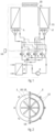
- Fig. 1 shows a schematic diagram of a heat pump system according to the embodiment of the present invention for a configuration in which evaporator 2 is being defrosted and evaporator 1 is active;
- Fig. 2 shows a schematic plan view of the heat pump system;
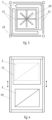
- Fig. 3 is a schematic cross section of the top of the heat pump system;
- Fig. 4 is a schematic side view of the heat pump;
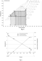
- Fig. 5 shows a temperature-entropy diagram of a cooling circuit provided by the heat pump for a preferred embodiment of the system and method according to example 4;
- Fig. 1 shows a schematic diagram of a heat pump system according to the embodiment of the present invention for a configuration in which evaporator 2 is being defrosted and evaporator 1 is active;
- Fig. 2 shows a schematic plan view of the heat pump system;
- Fig. 3 is a schematic cross section of the top of the heat pump system;
- Fig. 4 is a schematic side view of the heat pump;
- Fig. 6 shows the curve of the temperature change of the liquid refrigerant in the defrosting process, the temperature of the heat transfer surface and the amount of exchanged heat as a function of temperature and time, carried out the heat pump, for a preferred embodiment of the system and method according to example 4;
- Fig. 7 shows a diagram of the heating power of the device over 1 hour for the alternating system without a shutter, the reversing system and the system with a shutter according to the invention.
- the air-to-water heat pump system comprises a lower heat source unit and un upper heat source unit connected in a thermodynamic cycle, wherein the lower heat source unit is supplied with external air and the lower heat source has at least two alternately working evaporators 1, 2 forming the lower heat source with the fan 10 mounted axially in relation to the lower heat source unit in its upper part, provided with a defrosting unit.
- the alternately operating evaporators 1, 2 are connected to a set of valves comprising two pairs of motor-actuated three-way valves 3, 4 and 5, 6 for each evaporator 1 and 2, respectively, of the lower heat source provided with a shutter 11.
- the evaporators 1, 2 are connected in series in a closed circuit with the condenser 9.
- the outlet port of the first active evaporator 1 connects via the through hole of the second three-way valve 4 with the suction side of the compressor 8, connected on the discharge side to the condenser 9, the outlet port of which connects via the bypass of the third three-way valve 5 with the inlet of the second evaporator being defrosted 2, wherein the outlet of the second evaporator being defrosted 2 is connected via the bypass of the fourth three-way valve 6 with the expansion valve 7 and via the through hole of the first three-way valve 3 it connects with the inlet of the first active evaporator 1.
- the outlet port of the second active evaporator 2 connects via the bypass of the second three-way valve 4 with the suction side of the compressor 8, connected on the discharge side with the condenser 9, the outlet port of which connects via the through hole of the third three-way valve 5 with the inlet of the first evaporator being defrosted 1, wherein the outlet from the first evaporator being defrosted 1 connected via the through hole of the fourth three-way valve 6 with the expansion valve 7 and via the bypass of the first three-way valve 3 it connects with the inlet of the second active evaporator 2.
- the shutter 11 is formed on the lower heat source unit to shield the frosted evaporator 1 or 2 going into defrosting mode.
- the set of valves is provided with actuators connected to the controller 12 for automatically changing the circuit direction of the refrigerant and change the functions of the evaporators 1 and 2.
- the shutter 11 is connected with the controller 12 for automatically directing the shutter to a position shielding the evaporator being defrosted 1 or 2.
- the evaporators 1 and 2 forming the lower heat source are finned bent or segmented exchangers.
- the shutter 11 consists of an inner and an outer part which are thermally insulated.
- the heat pump circuit heats the water or glycol solution in the upper heat source.
- a method of optimizing the operation of an air-to-water heat pump which uses the alternating operation of at least two evaporators and the defrosting process of the second evaporator 2 is carried out by directing the refrigerant from the first active evaporator 1 via the through hole of the second three-way valve 4 to the compressor 8, then the refrigerant is directed to the condenser 9, then the liquefied refrigerant is directed via the bypass of the third three-way valve 5 to the second evaporator being defrosted 2, then the subcooled refrigerant is directed via the bypass of the fourth three-way valve 6 to the expansion valve 7, then the expanded refrigerant is directed via the through hole of the first three-way valve 3 to the first active evaporator, at the same time the rotary shutter 11 is directed to the position of shielding the second evaporator being defrosted 2.
- the defrosting process of the first evaporator 1 is carried out by directing the refrigerant from the second active evaporator 2 via the bypass of the second three-way valve 4 to the compressor 8, then the refrigerant is directed to the condenser 9, then the liquefied refrigerant is directed via the through hole of the third three-way valve 5 to the first evaporator being defrosted 1, then the subcooled refrigerant is directed via the through hole of the fourth three-way valve 6 to the expansion valve 7, then the expanded refrigerant is directed via the bypass of the first three-way valve 3 to the second active evaporator 2, at the same time the rotary shutter 11 is directed to the position of shielding the first evaporator being defrosted 1 to limit the heat exchange between the outside air and the shielded first evaporator being defrosted 1.
- the continuously operating fan 10 forces the external air flow around the exposed active evaporator 1 or 2.
- the defrosting process of evaporator 1 or 2 is carried out until the end of exchanger defrosting cycle, wherein the controller 12, by switching the three-way valves operation mode, generates another change of the refrigerant circulation direction, thus changing the functions of the evaporators 1, 2 and changing the position of the shutter 11 to the position of shielding the evaporator being defrosted 1 or 2.
- the alternately working evaporators 1, 2 are shaped as semi-circles forming a lower heat source of a cylindrical unit shape with a fan 10 mounted axially in relation to the lower heat source unit in its upper part.
- the shutter 11 is in the form of concentric semi-circles mounted on both sides of the evaporator, coaxially with the fan 10 of the lower heat source unit.
- the parts of shutter 11 are provided with a brush element 13 arranged along its height, preventing external air from infiltrating into the space between the evaporator being defrosted and the shutter, while maintaining the free movement of the shutter 11.
- the shutter 11 is automatically directed to the position of shielding the evaporator being defrosted 1 or 2 in a rotary motion ( fig. 2 ).
- the alternately working evaporators 1, 2 are shaped as closed polygons forming a lower heat source of a cuboidal unit shape with a fan 10 mounted axially in relation to the lower heat source assembly in its upper part.
- the evaporator 1 is located at the top of the lower heat source assembly and evaporator 2 is located at its bottom.
- the shutter 11 is in the form of a movable element in the form of a shield, adapted to change position via sliding means, mounted to a frame structure 14 on both sides of the evaporator 1, 2, wherein the shutter 11 has a shape corresponding to the shape of the evaporator 1, 2.
- the automatic orientation of the shutter 11 at position of shielding the defrosted evaporator 1 or 2 takes place in a reciprocating movement in the vertical direction ( fig. 3 and fig. 4 ).
- the heat pump circuit uses the natural refrigerant propane R290, wherein it was assumed that evaporator 2 is being defrosted and evaporator 1 is active.
- the compressor 8 compress the refrigerant (process 1-2 in Fig.5 ) in the amount of 300 kg/h which in the condenser 9 being the upper heat source transfers to the heating system a power of 37.9 kW (process 2-3 in Fig. 5 ).
- the liquefied refrigerant with a temperature of 47°C is directed to the evaporator being defrosted 2, where it is subcooled to 5°C (process 3-4), which increases the specific cooling capacity by 115 kJ/kg, while providing, at the same time, a heating power of 9.5 kW to the evaporator being defrosted 2, which ensures the sublimation of the ice layer.
- the refrigerant is throttled in the expansion valve (process 4-5) and then directed to the evaporator where it evaporates, recovering heat from the environment (process 5-1).
- a liquid refrigerant having a temperature of 47°C is directed to the evaporator 2 covered by the shutter 11.
- said evaporator 1, 2 of the system according to the invention has a finned part mass of 48 kg, of which copper is 22 kg and aluminium is 26 kg.
- the amount of heat needed to heat the heat exchanger to the defrosting end temperature is 290 kJ.
- the amount of heat needed to melt the entire frost layer taking into account the heat of fusion at the level of 333 kJ/kg, will be 5700 kJ.
- the mass of melted frost equal to 57%, flows from the surface of the heat exchanger and flows out of the system.
- the residual, of 43%, mass of the melted frost in the form of a moisture layer thick about 100 ⁇ m remains on the surface of the evaporator 1, 2.
- the partial pressure of the saturated water vapor at the temperature 0°C, and thus the frost melting temperature, is 612 Pa.
- the moisture exchange takes place according to the partial pressure difference between the water layer wetting the heat exchange surface and the surrounding air. Effective drying of the heat exchange surface requires that the partial pressure of water vapor on the heat exchanger surface is higher than the water vapor pressure in the surrounding air. Accordingly, the surface of the evaporator being defrosted 2 is heated to a temperature of at least 5°C, at which the water vapor pressure at the surface of said exchanger is 873 Pa.
- the obtained partial pressure difference of at least 260 Pa allows the surface of the evaporator 2 to be dried by evaporating the remaining moisture on its surface.
- the curve of the temperature change of the liquid refrigerant in the defrosting process of the evaporator 2, according to Fig. 6 is as follows:
- the liquid refrigerant having a temperature of 47°C flowing from the condenser 9 heats the heat exchanger, transferring during 115 s an amount of heat equal to 130 kJ, which causes heating of the heat exchanger from -4°C to 0°C, which allows to start the process of melting the frost layer, while reducing the refrigerant temperature 42°C.
- the process of melting the frost layer is completed after 780 s after the refrigerant transfers 5700 kJ of heat, which reduces the temperature of the refrigerant to 34°C.
- the defrosting cycle ends after the refrigerant supplies another 160 kJ of heat, during 230 s, which heats the heat exchange surface to 5°C, which ensures the drying of the heat exchanger surface and at the same time prevents deposition of moisture.
- the total defrost time is 3600 s.
- Fig. 5 shows the advantageous effect of the invention in the form of increasing the heat pump heating power.
- the heat flux transferred by the device to the heating system in relation to the time unit is equal to the surface area under the curve marked with diagonal hatching, i.e. the area defined by points 2-3-a-5-b-d. This area is significantly larger than the area marked with vertical hatching, defined by points 2-3-a-3*-c-d, which is a graphical representation of the heat pump heating power without defrosting in favour of subcooling the liquid refrigerant, i.e. heat pumps with a defrosting system known in the prior art.
- the increase of the heat pump heating power according to the invention achieved by the use of the shutter takes place without increasing the work required for the implementation of the circuit, described as the surface area determined by points 1-2-3-a.
- Fig.7 shows a further advantageous effect of the invention.
- the heat pump according to the invention transmits a constant heating power to the receiving system. Unlike in the reversible system and the system without a shutter, in which there is a periodic reduction or even a negative heat flux transferred to the heating system.
- An analysis of the technical parameters of the exemplary variant 4 shows that the air-to-water heat pump system according to the invention with a defrosting unit enables an energy-efficient implementation of the defrosting process.
- the shutter according to the invention enhances the defrosting effect, reducing the amount of energy and time required to complete the process.
- the use of the shutter according to the invention allows for an absolute drying of the exchanger being defrosted due to the maintenance of a higher temperature of the exchanger surface, and thus ensures a longer time of its operation in active mode.
Landscapes
- Engineering & Computer Science (AREA)
- Mechanical Engineering (AREA)
- General Engineering & Computer Science (AREA)
- Physics & Mathematics (AREA)
- Thermal Sciences (AREA)
- Chemical & Material Sciences (AREA)
- Combustion & Propulsion (AREA)
- Defrosting Systems (AREA)
- Heat-Pump Type And Storage Water Heaters (AREA)
Claims (11)
- Luft-Wasser-Wärmepumpensystem, das aufweist einen Kompressor (8), einen Kondensator (9), ein Expansionsventil (7), eine untere Wärmequelleneinheit und eine obere Wärmequelleneinheit, die in einem thermodynamischen Kreisprozess verbunden sind, wobei die untere Wärmequelleneinheit so ausgebildet ist, das sie mit Außenluft versorgt wird, und wobei die untere Wärmequelle mindestens zwei abwechselnd arbeitende Verdampfer (1, 2) aufweist, welche die untere Wärmequelle der Einheit bilden, wobei ein Ventilator axial in Bezug auf die untere Wärmequelleneinheit in ihrem oberen Teil montiert ist, und das mit einer Abtaueinheit versehen ist,wobei das Luft-Wasser-Wärmepumpensystem ferner ein Ventil-Set, das zwei Paare von motorbetriebenen Dreiwegeventilen (3, 4) und (5, 6) aufweist, die mit den mindestens zwei Verdampfern (1, 2) verbunden sind, und eine Blende (9) aufweist, die für jeden Verdampfer (1) und (2) der unteren Wärmequelleneinheit vorgesehen ist, wobei die Verdampfer (1, 2) in einem geschlossenen Kreis mit dem Kondensator (9) in Reihe geschaltet sind;wobei sich eine Auslassöffnung des ersten Verdampfers (1) über das Durchgangsloch des zweiten Dreiwegeventils (4) mit einer Ansaugseite des Kompressors (8) verbindet, der auf einer Auslassseite mit dem Kondensator (9) verbunden ist, dessen Auslassöffnung sich über den Bypass des dritten Dreiwegeventils (5) mit dem Einlass des zweiten Verdampfers (2) verbindet, wobei der Auslass des zweiten Verdampfers (2) über den Bypass des vierten Dreiwegeventils (6) mit dem Expansionsventil (7) verbunden ist, und wobei sich das Expansionsventil (7) über das Durchgangsloch des ersten Dreiwegeventils (3) mit dem Einlass des ersten Verdampfers (1) verbindet;wobei sich die Auslassöffnung des zweiten Verdampfers (2) über den Bypass des zweiten Dreiwegeventils (4) mit der Ansaugseite des Kompressors (8) verbindet, der auf der Auslassseite mit dem Kondensator (9) verbunden ist, dessen Auslassöffnung sich über das Durchgangsloch des dritten Dreiwegeventils (5) mit dem Einlass des ersten Verdampfers (1) verbindet, wobei der Auslass des ersten Verdampfers (1) über das Durchgangsloch des vierten Dreiwegeventils (6) mit dem Expansionsventil (7) verbunden ist, und wobei sich das Expansionsventil (7) über den Bypass des ersten Dreiwegeventils (3) mit dem Einlass des zweiten Verdampfers (2) verbindet;wobei die Blende (11) an der unteren Wärmequelleneinheit ausgebildet ist, um den vereisten Verdampfer (1, 2) durch Eintreten in einen Abtaumodus abzuschirmen.
- Wärmepumpensystem nach Anspruch 1, das ferner eine Steuerung (12) aufweist, wobei das Ventil-Set mit Aktuatoren versehen ist, die mit der Steuerung (12) verbunden sind, um die Kreislaufrichtung des Kältemittels automatisch zu ändern und die Funktionen der Verdampfer (1) und (2) zu ändern.
- Wärmepumpensystem nach Anspruch 1, wobei die Blende (11) mit der Steuerung (12) verbunden ist, um die Blende automatisch in die Position zur Abschirmung des abzutauenden Verdampfers (1) oder (2) zu bringen.
- Wärmepumpensystem nach Anspruch 1, wobei die Blende (11) automatisch in die Position zur Abschirmung des abzutauenden Verdampfers (1) oder (2) durch eine rotierende oder alternierende Bewegung in einer horizontalen oder vertikalen Richtung oder durch Schließen von Einzel- oder Mehrlamellenklappen gebracht wird.
- Wärmepumpensystem nach Anspruch 1, wobei die Verdampfer (1) und (2), welche die untere Wärmequelle bilden, gerippt gebogene oder segmentierte Wärmetauscher in Form eines offenen oder geschlossenen Vielecks, einschließlich eines regelmäßigen oder unregelmäßigen Vielecks, oder in Form einer Ebene oder eines Kreises, Halbkreises oder einer anderen unregelmäßigen Form sind.
- Wärmepumpensystem nach Anspruch 1, wobei die Blende (11) die Form von konzentrischen Halbkreisen aufweist, die auf beiden Seiten des Verdampfers (1, 2) koaxial zum Ventilator (10) der unteren Wärmequelle montiert sind.
- Wärmepumpensystem nach Anspruch 1, wobei die Blende (11) die Form eines bewegbaren Elements in Form einer Abschirmung oder einer Klappe hat, das seine Position durch Schiebemittel verändern kann, die an der Rahmenstruktur (14) auf beiden Seiten des Verdampfers (1, 2) montiert sind, wobei die Blende (11) eine Ausgestaltung aufweist, die der Form des Verdampfers (1, 2) entspricht.
- Wärmepumpensystem nach Anspruch 1, wobei die Blende (11) aus einem inneren und einem äußeren Teil besteht, die thermisch isoliert sind.
- Wärmepumpensystem nach Anspruch 1, wobei die Teile der Blende (11) mit einem Bürstenelement (13) versehen sind, das entlang seiner Höhe angeordnet ist, wodurch verhindert wird, dass Außenluft in den Raum zwischen dem abzutauenden Verdampfer und der Blende eindringt, während eine freie Bewegung der Blende (11) beibehalten wird.
- Wärmepumpensystem nach Anspruch 1, wobei der Wärmepumpenkreislauf dazu ausgebildet ist, das Wasser oder die Glykollösung in der oberen Wärmequelle zu erhitzen.
- Verfahren zur Optimierung des Betriebs der Luft-Wasser-Wärmepumpe, welches den Wechselbetrieb von mindestens zwei Verdampfern verwendet, wobei der Abtauvorgang des zweiten Verdampfers (2) ausgeführt wird, indem das Kältemittel aus dem ersten Verdampfer (1) über das Durchgangsloch des zweiten Dreiwegeventils (4) zum Kompressor (8) geleitet wird, das Kältemittel dann zum Kondensator (9) geleitet wird, das verflüssigte Kältemittel dann über den Bypass des dritten Dreiwegeventils (5) zum zweiten Verdampfer (2) geleitet wird, das unterkühlte Kältemittel dann über den Bypass des vierten Dreiwegeventils (6) zum Expansionsventil (7) geleitet wird, das expandierte Kältemittel dann über das Durchgangsloch des ersten Dreiwegeventils (3) zum ersten Verdampfer (1) geleitet wird, während gleichzeitig die Blende (11) in die Position zur Abschirmung des zweiten Verdampfers (2) gebracht wird;wobei der Abtauvorgang des ersten Verdampfers (1) ausgeführt wird, indem das Kältemittel aus dem zweiten Verdampfer (2) über den Bypass des zweiten Dreiwegeventils (4) zum Kompressor (8) geleitet wird, das Kältemittel dann zum Kondensator (9) geleitet wird, das verflüssigte Kältemittel dann über das Durchgangsloch des dritten Dreiwegeventils (5) zum ersten Verdampfer (1) geleitet wird, das unterkühlte Kältemittel dann über das Durchgangsloch des vierten Dreiwegeventils (6) zum Expansionsventil (7) geleitet wird, das expandierte Kältemittel dann über den Bypass des ersten Dreiwegeventils (3) zum zweiten Verdampfer (2) geleitet wird, während gleichzeitig die Blende (11) in die Position zur Abschirmung des ersten Verdampfers (1) gebracht wird, um den Wärmeaustausch zwischen der Außenluft und dem abgeschirmten ersten Verdampfer (1) zu begrenzen;wobei der kontinuierlich arbeitende Ventilator (10) die Außenluft dazu zwingt, um den freigelegten Verdampfer (1) oder (2) zu strömen;wobei der Abtauvorgang des Verdampfers (1) oder (2) bis zum Ende des Wärmetauscher-Abtauzyklus ausgeführt wird, wobei die Steuerung (12) durch Schalten des Dreiwegeventil-Betriebsmodus eine weitere Änderung der Kältemittel-Zirkulationsrichtung erzeugt, wodurch die Funktionen der Verdampfer (1, 2) geändert werden und die Position der Blende (11) in die Position zur Abschirmung des abzutauenden Verdampfers (1) oder (2) geändert wird.
Applications Claiming Priority (3)
| Application Number | Priority Date | Filing Date | Title |
|---|---|---|---|
| PL438230A PL243376B1 (pl) | 2021-06-22 | 2021-06-22 | Układ pompy ciepła powietrze-woda z rotacyjnym zespołem odtajania i sposób optymalizacji pracy pompy ciepła powietrze-woda |
| PL441486A PL242845B1 (pl) | 2021-06-22 | 2022-06-14 | Układ pompy ciepła powietrze-woda z zespołem odtajania i sposób optymalizacji pracy pompy ciepła powietrze-woda |
| PCT/PL2022/050040 WO2022271045A1 (en) | 2021-06-22 | 2022-06-22 | Air-to-water heat pump system with defrosting unit and method of optimizing the operation of the air-to-water heat pump |
Publications (3)
| Publication Number | Publication Date |
|---|---|
| EP4359712A1 EP4359712A1 (de) | 2024-05-01 |
| EP4359712C0 EP4359712C0 (de) | 2025-05-07 |
| EP4359712B1 true EP4359712B1 (de) | 2025-05-07 |
Family
ID=82939754
Family Applications (1)
| Application Number | Title | Priority Date | Filing Date |
|---|---|---|---|
| EP22755318.7A Active EP4359712B1 (de) | 2021-06-22 | 2022-06-22 | Luft-wasser-wärmepumpensystem mit abtaueinheit und verfahren zur optimierung des betriebs der luft-wasser-wärmepumpe |
Country Status (5)
| Country | Link |
|---|---|
| US (1) | US12607393B2 (de) |
| EP (1) | EP4359712B1 (de) |
| CA (1) | CA3223974A1 (de) |
| MD (1) | MD4359712T2 (de) |
| WO (1) | WO2022271045A1 (de) |
Families Citing this family (2)
| Publication number | Priority date | Publication date | Assignee | Title |
|---|---|---|---|---|
| CN118856447B (zh) * | 2024-07-15 | 2025-12-19 | 青岛海尔空调器有限总公司 | 空调系统及其控制方法 |
| CN119958144B (zh) * | 2025-03-20 | 2025-09-19 | 江苏纳奇机电设备工程有限公司 | 一种空气源热泵控制方法和系统 |
Family Cites Families (5)
| Publication number | Priority date | Publication date | Assignee | Title |
|---|---|---|---|---|
| US5685162A (en) * | 1991-04-26 | 1997-11-11 | Nippondenso Co., Ltd. | Automotive air conditioner having condenser and evaporator provided within air duct |
| US5680898A (en) * | 1994-08-02 | 1997-10-28 | Store Heat And Produce Energy, Inc. | Heat pump and air conditioning system incorporating thermal storage |
| GB9500160D0 (en) | 1995-01-05 | 1995-03-01 | British United Shoe Machinery | Chillers |
| CN206347790U (zh) | 2016-11-23 | 2017-07-21 | 珠海格力电器股份有限公司 | 一种空调系统 |
| CN207963222U (zh) | 2018-03-22 | 2018-10-12 | 罗良宜 | 一种热气旁通自动回流连续除霜装置 |
-
2022
- 2022-06-22 WO PCT/PL2022/050040 patent/WO2022271045A1/en not_active Ceased
- 2022-06-22 MD MDE20240469T patent/MD4359712T2/ro unknown
- 2022-06-22 EP EP22755318.7A patent/EP4359712B1/de active Active
- 2022-06-22 CA CA3223974A patent/CA3223974A1/en active Pending
- 2022-06-22 US US18/573,455 patent/US12607393B2/en active Active
Also Published As
| Publication number | Publication date |
|---|---|
| CA3223974A1 (en) | 2022-12-29 |
| MD4359712T2 (ro) | 2025-09-30 |
| US12607393B2 (en) | 2026-04-21 |
| US20240288208A1 (en) | 2024-08-29 |
| EP4359712C0 (de) | 2025-05-07 |
| WO2022271045A1 (en) | 2022-12-29 |
| EP4359712A1 (de) | 2024-05-01 |
Similar Documents
| Publication | Publication Date | Title |
|---|---|---|
| US7743621B2 (en) | Multi-range composite-evaporator type cross-defrosting system | |
| US9772124B2 (en) | Heat pump defrosting system and method | |
| US5269151A (en) | Passive defrost system using waste heat | |
| CN103759456B (zh) | 一种空调或热泵的换热系统及其除霜方法 | |
| US12607393B2 (en) | Air-to-water heat pump system with defrosting unit and method of optimizing the operation of the air-to-water heat pump | |
| CA2615689A1 (en) | An air conditioning heat pump with secondary compressor | |
| CA2636085A1 (en) | Thermal superconductor refrigeration system | |
| KR20120054321A (ko) | 히트 펌프 | |
| CN102759193B (zh) | 一种空气源热泵系统 | |
| CN104075486A (zh) | 二元热泵装置 | |
| KR100675900B1 (ko) | 냉동 공조 시스템 | |
| CN104344619A (zh) | 双系统热泵除霜方法及装置 | |
| LU500777B1 (en) | Air-water heat pump system with rotary defrosting unit and method for optimalization of the air-to-water heat pump operation | |
| CN114234503A (zh) | 除霜组件及其控制方法和空调系统 | |
| CN109073290A (zh) | 室外单元及具备该室外单元的制冷循环装置 | |
| JP2011237162A (ja) | 空気熱源ヒートポンプエアコンおよびその運転方法 | |
| JP6771302B2 (ja) | 空気調和機 | |
| CN203489560U (zh) | 双系统热泵除霜装置 | |
| KR20190023011A (ko) | 시설원예용 연속난방 공기조화 시스템 | |
| PL242845B1 (pl) | Układ pompy ciepła powietrze-woda z zespołem odtajania i sposób optymalizacji pracy pompy ciepła powietrze-woda | |
| HK40108999A (en) | Air-to-water heat pump system with defrosting unit and method of optimizing the operation of the air-to-water heat pump | |
| CN117881936A (zh) | 具有除霜单元的空气-水热泵系统和优化空气-水热泵操作的方法 | |
| CN102853601A (zh) | 热泵的除霜装置 | |
| CN215490427U (zh) | 一种无霜热泵装置 | |
| CN211876411U (zh) | 连续制热的空调机组 |
Legal Events
| Date | Code | Title | Description |
|---|---|---|---|
| STAA | Information on the status of an ep patent application or granted ep patent |
Free format text: STATUS: UNKNOWN |
|
| STAA | Information on the status of an ep patent application or granted ep patent |
Free format text: STATUS: THE INTERNATIONAL PUBLICATION HAS BEEN MADE |
|
| PUAI | Public reference made under article 153(3) epc to a published international application that has entered the european phase |
Free format text: ORIGINAL CODE: 0009012 |
|
| STAA | Information on the status of an ep patent application or granted ep patent |
Free format text: STATUS: REQUEST FOR EXAMINATION WAS MADE |
|
| 17P | Request for examination filed |
Effective date: 20240122 |
|
| AK | Designated contracting states |
Kind code of ref document: A1 Designated state(s): AL AT BE BG CH CY CZ DE DK EE ES FI FR GB GR HR HU IE IS IT LI LT LU LV MC MK MT NL NO PL PT RO RS SE SI SK SM TR |
|
| DAX | Request for extension of the european patent (deleted) | ||
| RAV | Requested validation state of the european patent: fee paid |
Extension state: MD Effective date: 20240122 |
|
| GRAP | Despatch of communication of intention to grant a patent |
Free format text: ORIGINAL CODE: EPIDOSNIGR1 |
|
| STAA | Information on the status of an ep patent application or granted ep patent |
Free format text: STATUS: GRANT OF PATENT IS INTENDED |
|
| INTG | Intention to grant announced |
Effective date: 20241218 |
|
| GRAS | Grant fee paid |
Free format text: ORIGINAL CODE: EPIDOSNIGR3 |
|
| GRAA | (expected) grant |
Free format text: ORIGINAL CODE: 0009210 |
|
| STAA | Information on the status of an ep patent application or granted ep patent |
Free format text: STATUS: THE PATENT HAS BEEN GRANTED |
|
| AK | Designated contracting states |
Kind code of ref document: B1 Designated state(s): AL AT BE BG CH CY CZ DE DK EE ES FI FR GB GR HR HU IE IS IT LI LT LU LV MC MK MT NL NO PL PT RO RS SE SI SK SM TR |
|
| REG | Reference to a national code |
Ref country code: GB Ref legal event code: FG4D |
|
| REG | Reference to a national code |
Ref country code: CH Ref legal event code: EP |
|
| REG | Reference to a national code |
Ref country code: DE Ref legal event code: R096 Ref document number: 602022014408 Country of ref document: DE |
|
| REG | Reference to a national code |
Ref country code: IE Ref legal event code: FG4D |
|
| VSFP | Annual fee paid to validation state [announced via postgrant information from national office to epo] |
Ref country code: MD Payment date: 20250613 Year of fee payment: 4 |
|
| U01 | Request for unitary effect filed |
Effective date: 20250606 |
|
| U07 | Unitary effect registered |
Designated state(s): AT BE BG DE DK EE FI FR IT LT LU LV MT NL PT RO SE SI Effective date: 20250616 |
|
| PGFP | Annual fee paid to national office [announced via postgrant information from national office to epo] |
Ref country code: AT Payment date: 20250721 Year of fee payment: 4 |
|
| REG | Reference to a national code |
Ref country code: MD Ref legal event code: VAGR Ref document number: 4359712 Country of ref document: MD Date of ref document: 20250930 Kind code of ref document: T2 |
|
| PG25 | Lapsed in a contracting state [announced via postgrant information from national office to epo] |
Ref country code: ES Free format text: LAPSE BECAUSE OF FAILURE TO SUBMIT A TRANSLATION OF THE DESCRIPTION OR TO PAY THE FEE WITHIN THE PRESCRIBED TIME-LIMIT Effective date: 20250507 |
|
| PG25 | Lapsed in a contracting state [announced via postgrant information from national office to epo] |
Ref country code: GR Free format text: LAPSE BECAUSE OF FAILURE TO SUBMIT A TRANSLATION OF THE DESCRIPTION OR TO PAY THE FEE WITHIN THE PRESCRIBED TIME-LIMIT Effective date: 20250808 |
|
| PG25 | Lapsed in a contracting state [announced via postgrant information from national office to epo] |
Ref country code: PL Free format text: LAPSE BECAUSE OF FAILURE TO SUBMIT A TRANSLATION OF THE DESCRIPTION OR TO PAY THE FEE WITHIN THE PRESCRIBED TIME-LIMIT Effective date: 20250507 |
|
| PG25 | Lapsed in a contracting state [announced via postgrant information from national office to epo] |
Ref country code: HR Free format text: LAPSE BECAUSE OF FAILURE TO SUBMIT A TRANSLATION OF THE DESCRIPTION OR TO PAY THE FEE WITHIN THE PRESCRIBED TIME-LIMIT Effective date: 20250507 |
|
| PGFP | Annual fee paid to national office [announced via postgrant information from national office to epo] |
Ref country code: CH Payment date: 20250714 Year of fee payment: 4 |
|
| PG25 | Lapsed in a contracting state [announced via postgrant information from national office to epo] |
Ref country code: RS Free format text: LAPSE BECAUSE OF FAILURE TO SUBMIT A TRANSLATION OF THE DESCRIPTION OR TO PAY THE FEE WITHIN THE PRESCRIBED TIME-LIMIT Effective date: 20250807 |
|
| PGFP | Annual fee paid to national office [announced via postgrant information from national office to epo] |
Ref country code: IE Payment date: 20250914 Year of fee payment: 4 |
|
| U20 | Renewal fee for the european patent with unitary effect paid |
Year of fee payment: 4 Effective date: 20250916 |
|
| PG25 | Lapsed in a contracting state [announced via postgrant information from national office to epo] |
Ref country code: IS Free format text: LAPSE BECAUSE OF FAILURE TO SUBMIT A TRANSLATION OF THE DESCRIPTION OR TO PAY THE FEE WITHIN THE PRESCRIBED TIME-LIMIT Effective date: 20250907 |
|
| PG25 | Lapsed in a contracting state [announced via postgrant information from national office to epo] |
Ref country code: SM Free format text: LAPSE BECAUSE OF FAILURE TO SUBMIT A TRANSLATION OF THE DESCRIPTION OR TO PAY THE FEE WITHIN THE PRESCRIBED TIME-LIMIT Effective date: 20250507 |
|
| PG25 | Lapsed in a contracting state [announced via postgrant information from national office to epo] |
Ref country code: CZ Free format text: LAPSE BECAUSE OF FAILURE TO SUBMIT A TRANSLATION OF THE DESCRIPTION OR TO PAY THE FEE WITHIN THE PRESCRIBED TIME-LIMIT Effective date: 20250507 |
|
| PG25 | Lapsed in a contracting state [announced via postgrant information from national office to epo] |
Ref country code: SK Free format text: LAPSE BECAUSE OF FAILURE TO SUBMIT A TRANSLATION OF THE DESCRIPTION OR TO PAY THE FEE WITHIN THE PRESCRIBED TIME-LIMIT Effective date: 20250507 |
|
| PG25 | Lapsed in a contracting state [announced via postgrant information from national office to epo] |
Ref country code: MC Free format text: LAPSE BECAUSE OF FAILURE TO SUBMIT A TRANSLATION OF THE DESCRIPTION OR TO PAY THE FEE WITHIN THE PRESCRIBED TIME-LIMIT Effective date: 20250507 |
|
| PLBE | No opposition filed within time limit |
Free format text: ORIGINAL CODE: 0009261 |
|
| STAA | Information on the status of an ep patent application or granted ep patent |
Free format text: STATUS: NO OPPOSITION FILED WITHIN TIME LIMIT |
|
| REG | Reference to a national code |
Ref country code: CH Ref legal event code: L10 Free format text: ST27 STATUS EVENT CODE: U-0-0-L10-L00 (AS PROVIDED BY THE NATIONAL OFFICE) Effective date: 20260318 |
|
| 26N | No opposition filed |
Effective date: 20260210 |
|
| REG | Reference to a national code |
Ref country code: CH Ref legal event code: U11 Free format text: ST27 STATUS EVENT CODE: U-0-0-U10-U11 (AS PROVIDED BY THE NATIONAL OFFICE) Effective date: 20260701 |
|
| PGFP | Annual fee paid to national office [announced via postgrant information from national office to epo] |
Ref country code: NO Payment date: 20260520 Year of fee payment: 5 |
|
| VSFP | Annual fee paid to validation state [announced via postgrant information from national office to epo] |
Ref country code: MD Payment date: 20260512 Year of fee payment: 5 |
|
| U20 | Renewal fee for the european patent with unitary effect paid |
Year of fee payment: 5 Effective date: 20260630 |
|
| PG25 | Lapsed in a contracting state [announced via postgrant information from national office to epo] |
Ref country code: CY Free format text: LAPSE BECAUSE OF FAILURE TO SUBMIT A TRANSLATION OF THE DESCRIPTION OR TO PAY THE FEE WITHIN THE PRESCRIBED TIME-LIMIT Effective date: 20250507 |