EP4359289B1 - Fahrzeugkarosserie mit verstärktem untergestell - Google Patents
Fahrzeugkarosserie mit verstärktem untergestell Download PDFInfo
- Publication number
- EP4359289B1 EP4359289B1 EP22727964.3A EP22727964A EP4359289B1 EP 4359289 B1 EP4359289 B1 EP 4359289B1 EP 22727964 A EP22727964 A EP 22727964A EP 4359289 B1 EP4359289 B1 EP 4359289B1
- Authority
- EP
- European Patent Office
- Prior art keywords
- floor
- supports
- box
- reinforcement
- seat
- Prior art date
- Legal status (The legal status is an assumption and is not a legal conclusion. Google has not performed a legal analysis and makes no representation as to the accuracy of the status listed.)
- Active
Links
Images
Classifications
-
- B—PERFORMING OPERATIONS; TRANSPORTING
- B62—LAND VEHICLES FOR TRAVELLING OTHERWISE THAN ON RAILS
- B62D—MOTOR VEHICLES; TRAILERS
- B62D25/00—Superstructure or monocoque structure sub-units; Parts or details thereof not otherwise provided for
- B62D25/20—Floors or bottom sub-units
-
- B—PERFORMING OPERATIONS; TRANSPORTING
- B60—VEHICLES IN GENERAL
- B60K—ARRANGEMENT OR MOUNTING OF PROPULSION UNITS OR OF TRANSMISSIONS IN VEHICLES; ARRANGEMENT OR MOUNTING OF PLURAL DIVERSE PRIME-MOVERS IN VEHICLES; AUXILIARY DRIVES FOR VEHICLES; INSTRUMENTATION OR DASHBOARDS FOR VEHICLES; ARRANGEMENTS IN CONNECTION WITH COOLING, AIR INTAKE, GAS EXHAUST OR FUEL SUPPLY OF PROPULSION UNITS IN VEHICLES
- B60K1/00—Arrangement or mounting of electrical propulsion units
- B60K1/04—Arrangement or mounting of electrical propulsion units of the electric storage means for propulsion
- B60K2001/0405—Arrangement or mounting of electrical propulsion units of the electric storage means for propulsion characterised by their position
- B60K2001/0438—Arrangement under the floor
Definitions
- the invention relates to a vehicle body with a reinforced underbody at a floor and seat supports, as well as to a vehicle comprising such a body.
- the document DE102019203045 describes a vehicle comprising a floor extending between a central tunnel and a side member, both oriented longitudinally to the vehicle.
- the central tunnel extends along the centerline of the vehicle and the side member along a lateral edge.
- Two parallel cross members extend across the floor, from the side member to the tunnel, and have attachment areas on which a seat is attached.
- the seat extends above the space between the two cross members.
- a battery is installed in this space between the two cross members, carried by a support fixed to said cross members, and more particularly on the face of the cross members opposite the seat.
- the document WO2013053433 describes a vehicle body according to the preamble of independent claim 1, with an underbody, the underbody comprising with a central tunnel and a side member both extending in a direction longitudinal to the vehicle body, and seat supports extending longitudinally, one along the tunnel and the other along the side member.
- one of the aims of the invention is to propose a vehicle with a battery under a seat, of reduced mass, of simple design to produce, while ensuring effective protection of the battery and of the passage seated on the seat in the event of a side impact.
- a vehicle body comprising a base which comprises a central tunnel, a lateral side member both extending in a longitudinal direction to the body, and a floor comprising an inner face oriented towards the inside of the body, the floor extending between the central tunnel and the side member, the base further comprising a first seat support extending longitudinally along the tunnel and the inner face of the floor, fixed to said tunnel and to said floor, a second seat support extending longitudinally along the side member and the inner face of the floor, fixed to said side member and to said floor, opposite the first support, said first and second supports each comprising an upper face distant from the inner face of the floor, so that the first and second supports project relative to the inner face of the floor, the upper faces comprising fixing interfaces for fixing a seat, remarkable in that a reinforcing cross member extends between the two supports, at a distance from the floor, fixed by each of its ends to each of the supports.
- the body provides effective protection for a system such as a battery tray comprising a battery, installed at least partly between the two supports, under the reinforcing cross member, while maintaining space between the supports.
- a system such as a battery tray comprising a battery
- the reinforcing cross member reduces the proximity between the two supports, and reduces the risk of crushing the system.
- This solution is also simple to implement, in particular by reducing the number and mass of parts to be fixed to the vehicle body. It also reduces the modifications required to an existing vehicle body, which already includes supports, to accommodate such a system between the seat supports. Another advantage is that the system remains accessible when a seat is fixed to the supports.
- the seat attachment interfaces are located on each of the ends of the upper faces of the supports oriented on the same side of the body, and the reinforcing crossmember is fixed to the supports by said attachment interfaces located on each of the ends of the supports oriented on the same side of the body.
- the reinforcing crossmember is fixed on the attachment interfaces located on the ends of the supports located towards the front of the body, the front of the body corresponding to the front of a vehicle comprising such a body.
- the reinforcing crossmember is arranged so as to flex in the opposite direction of the floor in the event of a transverse force oriented from one end towards the other of the reinforcing crossmember.
- the reinforcing crossmember deforms and flexes in the opposite direction to the floor, so as not to press on a system, such as for example a battery, installed between said reinforcing crossmember and the floor, reducing the risks of damaging the system.
- the reinforcing crossmember comprises a substantially rectilinear body and fixing means at each end of the body, the fixing means being offset towards the floor relative to the body of the reinforcing crossmember.
- the force injected into the body of the reinforcement crossmember by the fixing means promotes the bending of the reinforcement crossmember.
- the base comprises a seat crosspiece extending from the first support to the second support, connected at one of its ends to the first support between the fixing interfaces located on the first support, in the longitudinal direction, and at its other end to the second support between the fixing interfaces located on the second support, in the longitudinal direction, the seat crosspiece being fixed to the floor.
- the seat crossmember limits the approach of the second support towards the first support, reducing the risks of damage to the system installed under the reinforcement crossmember and improving the safety of a passage installed on a seat fixed to the supports.
- the base comprises a reinforcing plate on the inner face of the floor, fixed to said floor, extending at least partly between the supports and opposite the reinforcing crossmember.
- the reinforcing plate comprises one or more fixing zones for a battery tray so as to hold said battery tray on the reinforcing plate.
- the reinforcement plate reinforces the floor between the supports, and reduces the risks of deformation of the latter in the event of a side impact, so as to limit the rimpedement between the two supports, and in fact reducing the risks of damage to a system installed between said supports.
- the reinforcement plate comprises a relief projecting from the opposite side of the floor, along the front edge of said reinforcement plate facing the front of the body.
- the relief extends in a direction transverse to the body.
- the relief makes it possible to create a border on which a system, such as a battery tray placed on the reinforcement plate, can be blocked in the event of a front impact.
- the base comprises a protective plate arranged opposite the outer face of the floor and fixed to the base, the outer face being the face of the floor opposite the inner face.
- the base comprises, on the outside of the body, a stretcher extension extending longitudinally on the outside face of the floor, and a tunnel reinforcement arranged at the junction between the tunnel and the floor so as to reinforce this junction, the protective plate being fixed by one of these edges to the stretcher extension and by an edge opposite the tunnel reinforcement, at least partly opposite the reinforcement plate.
- the protective plate forms a screen under the floor preventing an object from passing through the floor and damaging a system installed on the reinforcement plate, such as a battery.
- a system installed on the reinforcement plate such as a battery.
- it stiffens the floor against forces in the transverse direction, reducing the risks of the second support moving towards the first support in the event of a side impact.
- the invention also relates to a vehicle comprising a body as described above, and a battery tray arranged at least partly between the supports and under the reinforcement crossmember.
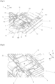
- FIG. 1 shows a base 1 of a motor vehicle body, on the inside of the vehicle, which comprises a central tunnel 2 and a lateral side member 3 both extending in a longitudinal direction X to the body, and a floor 4 extending between the central tunnel 2 and the side member 3.
- the X axis represents the longitudinal direction of the vehicle
- the Y axis the transverse direction
- the Z axis the vertical direction.
- the front, rear, top, bottom directions are taken in the reference frame of the vehicle comprising the body.
- the floor 4 extends substantially parallel to the longitudinal X and transverse Y axes.
- the base 1 comprises a first seat support 51 extending longitudinally along the tunnel 2 and the floor 4, fixed to said tunnel 2 and to said floor 4, as well as a second seat support 52 extending longitudinally along the side member 3 and the floor 4, fixed to said side member 3 and to said floor 4, opposite the first support 51 along the transverse axis Y.
- the two supports 51 are distant from each other along this transverse axis Y of the vehicle.
- the first 51 and second 52 supports each comprise an upper face distant from an inner face of the floor 4, the inner face being the face of the floor facing the inner side of the body. In other words, the first 51 and second 52 supports project relative to the inner face of the floor 4, in height relative to the floor.
- the upper faces comprise fixing interfaces 61, 62 for a seat.
- the seat fixing interfaces 61, 62 are located on each of the ends of the upper faces of the supports 51, 52 oriented on the same side of the body 1. That is to say that the first support 51 comprises two fixing interfaces 61, each arranged at each end of said first support 51, on the upper face of said first support 51, and the second support 52 comprises two fixing interfaces 62, also each arranged at each end of the second support 52, on the upper face of said support 52.
- the reinforcing crossmember 7 is fixed to the supports 51, 52 with said fixing interfaces 61, 62 located on each of the ends of the supports 51, 52 oriented towards the front of the body, the front of the body corresponding to the front of the vehicle. That is to say that the reinforcing crossmember 7 extends between the two ends of the first and second reinforcements 51 and 52 which are oriented towards the front of the vehicle.
- These fixing interfaces 61, 62 arranged at these front ends of said supports 51, 52 are therefore used to fix both the seat and the reinforcing crossmember 7.
- the reinforcing crosspiece 7 is for example arranged so as to flex in the opposite direction to the floor 4 in the event of a transverse force, that is to say in the transverse direction Y, oriented from one end towards the other of the reinforcing crosspiece 7. It has for example a lower mechanical resistance on the side of its face oriented towards the floor 4 than on that oriented away from the floor 4.
- the reinforcing crosspiece 7 is for example made of a flattened tubular profile, comprising a first wall and a second wall parallel to each other, extending substantially along the X and Y axes, the first wall extending above and opposite the second wall, with the second wall opposite the floor 4; the thickness of the second wall is for example chosen to be less than the thickness of the first wall to obtain the desired deflection, opposite the floor 4 when a force is applied to the reinforcing crosspiece 7, oriented from one end to the other of said reinforcing crosspiece 7.
- the reinforcing crossmember 7 comprises a substantially rectilinear body 70 and fixing means 71, 72 at each of the ends of the body 70; the fixing means 71, 72 are offset towards the floor 4 relative to the body 70 of the reinforcing crossmember 7, i.e. in the vertical direction Z. This offset promotes the bending of the reinforcing crossmember 7 when a force oriented from one end to the other of said reinforcing crossmember 7 is applied to said reinforcing crossmember 7, for example in the event of a side impact.
- a seat crosspiece 53 extends from the first support 51 to the second support 52. It is connected at one of its ends to the first support 51, between the fixing interfaces 61 located on said first support 51 in the longitudinal direction X, and at its other end to the second support 52 between the fixing interfaces 62 located on said second support 52 in the longitudinal direction X.
- the seat crosspiece 53 is for example fixed to the floor 4, and extends over the entire height of the supports 51, 52, the height being the dimension in the vertical direction Z, that is to say that the seat crosspiece 53 has an upper face which is substantially aligned with the upper faces of the supports 51, 52. Other heights for the seat crosspiece 53 can be chosen.
- the seat crosspiece 53 rests on side walls of the supports 51, 52, the respective side walls of the supports 51, 52 being the walls extending between the upper face of each of the supports 51, 52 and the floor 4, delimiting the space between the two supports 51, 52.
- the side wall of the first support 51 is therefore opposite the side wall of the second support 52.
- the junction between the seat crosspiece 53 and each of the two supports 51, 52 is substantially in the middle of the length of said supports 51, 52, the length being the dimension taken in the longitudinal direction X.
- a reinforcing plate 8 is arranged on the inner face of the floor 4. It extends at least partly between the supports 51, 52 and opposite the reinforcing crossmember 7. It is fixed to the floor 4 and comprises one or more fixing zones 81 for fixing a battery tray 10.
- the battery tray 10 is positioned on the reinforcing plate 8.
- the reinforcing plate 8 may extend outside the space between the supports 51, 52. For example, as illustrated in Figure 1 , the reinforcing plate 8 extends towards the front of the vehicle along the longitudinal axis X, from the seat cross member 53 and beyond the front ends of the supports 51, 52. It therefore comprises a part facing the reinforcing cross member 7.
- the surface of the reinforcing plate 10 covers at least the footprint of the battery tray in the plane parallel to the axes X and Y, so as to receive the entire battery tray 10, the reinforcing plate 4 extending substantially parallel to the axes X and Y.
- the reinforcing plate 8 comprises a relief 80 projecting from the opposite side of the floor 4, along the front edge of said reinforcing plate 8 oriented towards the front of the body.
- the relief 80 extends parallel to the transverse direction Y, along the front edge of said reinforcing plate 8, over more than half the width of the reinforcing plate 8 at its front edge, the width corresponding to the dimension along the transverse axis Y.
- the battery tray 10 installed on the reinforcing plate 8 is placed in abutment or close to the relief 80, for example less than 1 centimeter from the relief, behind the relief 80 in the longitudinal direction X, so as to restrain a forward movement of the vehicle of said battery tray 10 in the event of a front impact.
- the reinforcing plate 8 is for example made from a stamped sheet metal, and the relief 80 obtained by deformation of the sheet metal forms a hollow on the face of said reinforcing plate 8 facing the floor 4.
- a reinforcing piece is installed in the hollow forming the relief 80, for example fixed by gluing or welding to said reinforcing plate 8.
- the relief 80 can be produced directly by a piece fixed to the reinforcing plate 8, on the side of the reinforcing plate 8 opposite the floor 4 and arranged so as to create the relief 8.
- the reinforcement plate 8 may comprise several reliefs 80 arranged along its front edge.
- the reinforcing plate 8 may include stiffening ribs extending parallel to the transverse axis Y.
- the reinforcing plate 8 comprises one or more fixing zones 81.
- it may comprise a front fixing zone 81 on a front part of the reinforcing plate 8, behind the relief 80, and a rear fixing zone arranged in the rear part of the reinforcing plate 8.
- the front part corresponds to the part of the reinforcing plate 8 arranged in front of the reinforcing crosspiece 7 and the rear part to the part behind said reinforcing crosspiece 7, along the longitudinal axis X.
- the base 1 comprises a protective plate 9 arranged opposite the outer face of the floor 4 and fixed to the base 1, the outer face being the face of the floor 4 opposite the inner face.
- the outer face of the floor 4 is therefore located on the outside of the body.
- the protective plate 9 is therefore on the side of the outer face of the floor 4, outside the body.
- the base 1 comprises on the outside, that is to say on the side of the outer face of the floor 4, a stretcher extension 11, extending longitudinally on the outer face of the floor 4, and a tunnel reinforcement 12 arranged at the junction between the tunnel 2 and the floor 4.
- the tunnel reinforcement 12 makes it possible to reinforce the junction between the tunnel 2 and the floor 4.
- the stretcher extension 11 is for example a structural element of the base 1 arranged in the extension of a front stretcher, projecting relative to the outer face of the floor 4.
- the protective plate 9 is fixed by one of these edges to the stretcher extension 11 and by an edge opposite the tunnel reinforcement 12, at least partly opposite the reinforcement plate 8.
- the stretcher extension 11 comprises two lateral faces extending along the vertical axis Z and longitudinal axis X, and a lower face connecting the lateral faces, extending along the longitudinal axis X and the transverse axis Y, and distant from the floor 4, the protective plate 9 being fixed on this lower face.
- the floor 4 is for example a front floor 4 of a vehicle, and the supports 51, 52 are front seat supports, such as the driver's seat or the passenger seat.
Landscapes
- Engineering & Computer Science (AREA)
- Chemical & Material Sciences (AREA)
- Combustion & Propulsion (AREA)
- Transportation (AREA)
- Mechanical Engineering (AREA)
- Body Structure For Vehicles (AREA)
Claims (10)
- Fahrzeugkarosserie mit einem Untergestell (1), das einen Mitteltunnel (2), einen sich beide in Längsrichtung (X) zum Untergestell erstreckenden Seitenholm (3) und einen Untergestell (4) mit einer nach innen gerichteten Innenseite des Untergestells umfasst, wobei sich der Unterboden (4) zwischen dem Mitteltunnel (2) und dem Längsträger (3) erstreckt 1) ferner mit einem ersten Sitzträger (51), der sich in Längsrichtung entlang des Tunnels (2) und der Innenseite des Bodens (4) erstreckt und an dem Tunnel (2) und dem Boden (4) befestigt ist, einem zweiten Sitzträger (52), der sich in Längsrichtung entlang des Längsträgers (3) und der Innenseite des Bodens (4) erstreckt, der an dem Boden (4) befestigt ist, Gegenüber dem ersten Träger (51) weisen die ersten und zweiten Träger (51, 52) jeweils eine von der Innenseite des Bodens (4) beabstandete Oberseite auf, sodass die ersten und zweiten Träger (51, 52) von der Innenseite des Bodens (4) vorstehen, wobei die Oberseite Befestigungsflächen (61, 62) zur Befestigung eines Sitz, wobei der Kasten dadurch gekennzeichnet ist, dass sich zwischen den beiden Trägern (51, 52) im Abstand zum Boden (4) ein Verstärkungssteg (7) erstreckt, der mit jedem seiner Enden an jedem der Träger (51, 52) befestigt ist.
- Kasten nach Anspruch 1, dessen Sitzbefestigungsschnittstellen (61, 62) an jedem der Enden der Oberseiten der Träger (51, 52) angeordnet sind, die auf der gleichen Seite des Kastens ausgerichtet sind, und der Verstärkungssteg (7) an den Trägern (51, 52) an ihrer jeweiligen Oberseite mit den Befestigungsschnittstellen (61, 62) befestigt ist An jedem der Enden der Träger (51, 52), die auf derselben Seite des Aufbaus, vorzugsweise nach vorn, ausgerichtet sind, entspricht die Vorderseite des Aufbaus der Vorderseite eines Fahrzeugs mit einem solchen Kasten.
- Kasten nach einem der vorhergehenden Ansprüche, dessen Verstärkungssteg (7) so angeordnet ist, dass er bei einer von einem Ende des Verstärkungsstegs (7) zum anderen gerichteten Querkraft in entgegengesetzter Richtung zum Boden (4) abbiegt.
- Kasten nach Anspruch 3, dessen Verstärkungssteg (7) einen im Wesentlichen geradlinigen Körper (70) und Befestigungsmittel (71, 72) an jedem Ende des Körpers (70) aufweist, wobei die Befestigungsmittel (71, 72) gegenüber dem Körper (70) des Verstärkungssteges (7) versetzt sind.
- Kasten nach einem der vorhergehenden Ansprüche, bei dem der Unterbau (1) einen Sitzträger (53) umfasst, der sich von dem ersten Träger (51) zum zweiten Träger (52) erstreckt und mit einem dieser Enden mit dem ersten Träger (51) zwischen den Befestigungsschnittstellen (61) auf dem ersten Träger (51) in Längsrichtung (X) verbunden ist, und Das andere Ende des zweiten Trägers (52) zwischen den Befestigungsschnittstellen (62) auf dem zweiten Träger (52) in Längsrichtung (X), wobei der Sitzsteg (53) am Boden (4) befestigt ist.
- Kasten nach einem der vorhergehenden Ansprüche mit einer Verstärkungsplatte (8) auf der Innenseite des Bodens (4), die an dem Boden (4) befestigt ist und sich zumindest teilweise zwischen den Trägern (51, 52) und der Verstärkungstraverse (7) erstreckt, vorzugsweise mit einem Befestigungsbereich (81) für einen Batteriebehälter (10).
- Kasten nach Anspruch 6, dessen Verstärkungsplatte (8) eine Erhebung (80) aufweist, die auf der gegenüberliegenden Seite des Bodens (4) entlang des vorderen Randes der Verstärkungsplatte (8), der nach vorne gerichtet ist, vorsteht, vorzugsweise die Erhebung (80), die sich in einer Querrichtung (Y) zum Kasten erstreckt.
- Kasten nach einem der vorhergehenden Ansprüche, bei dem der Unterbau (1) eine Schutzplatte (9) aufweist, die gegenüber der Außenseite des Bodens (4) angeordnet und am Unterbau (1) befestigt ist, wobei die Außenseite die der Innenseite gegenüberliegende Seite des Bodens ist.
- Kasten nach Anspruch 8 und einem der Ansprüche 6 oder 7, dessen Unterbau (1) an der Außenseite des Kastens eine sich längs erstreckende Schenkelverlängerung (11) auf der Außenseite des Bodens (4) und eine Tunnelverstärkung (12) aufweist, die an der Verbindung zwischen dem Tunnel (2) und dem Boden (4) angeordnet ist, um diese Verbindung zu verstärken 9) mit einem dieser Ränder an der Trägerverlängerung (11) und mit einem der Tunnelverstärkung (12) gegenüberliegenden Rand zumindest teilweise gegenüber der Verstärkungsplatte (8) befestigt ist.
- Fahrzeug mit einem Kasten nach einem der vorhergehenden Ansprüche und einem Batteriebehälter, der zumindest teilweise zwischen den Trägern (51, 52) und unter dem Verstärkungsträger (7) angeordnet ist.
Applications Claiming Priority (2)
| Application Number | Priority Date | Filing Date | Title |
|---|---|---|---|
| FR2106547A FR3124152B1 (fr) | 2021-06-21 | 2021-06-21 | Caisse de véhicule comportant un soubassement renforcé. |
| PCT/FR2022/050850 WO2022269148A1 (fr) | 2021-06-21 | 2022-05-03 | Caisse de véhicule comportant un soubassement renforcé |
Publications (2)
| Publication Number | Publication Date |
|---|---|
| EP4359289A1 EP4359289A1 (de) | 2024-05-01 |
| EP4359289B1 true EP4359289B1 (de) | 2025-06-25 |
Family
ID=77226906
Family Applications (1)
| Application Number | Title | Priority Date | Filing Date |
|---|---|---|---|
| EP22727964.3A Active EP4359289B1 (de) | 2021-06-21 | 2022-05-03 | Fahrzeugkarosserie mit verstärktem untergestell |
Country Status (4)
| Country | Link |
|---|---|
| EP (1) | EP4359289B1 (de) |
| CN (1) | CN117615958A (de) |
| FR (1) | FR3124152B1 (de) |
| WO (1) | WO2022269148A1 (de) |
Family Cites Families (3)
| Publication number | Priority date | Publication date | Assignee | Title |
|---|---|---|---|---|
| FR2106547B1 (de) | 1970-09-16 | 1975-02-21 | Werkzeugmasch Heckert Veb | |
| DE102011115763A1 (de) * | 2011-10-12 | 2013-04-18 | Volkswagen Aktiengesellschaft | Aufbaustruktur für ein elektrisch angetriebenes Personen-Kraftfahrzeug |
| DE102019203045A1 (de) | 2019-03-06 | 2020-09-10 | Ford Global Technologies, Llc | Batterieanordnung für ein Hybridkraftfahrzeug |
-
2021
- 2021-06-21 FR FR2106547A patent/FR3124152B1/fr active Active
-
2022
- 2022-05-03 EP EP22727964.3A patent/EP4359289B1/de active Active
- 2022-05-03 CN CN202280044203.3A patent/CN117615958A/zh active Pending
- 2022-05-03 WO PCT/FR2022/050850 patent/WO2022269148A1/fr not_active Ceased
Also Published As
| Publication number | Publication date |
|---|---|
| CN117615958A (zh) | 2024-02-27 |
| FR3124152B1 (fr) | 2023-05-05 |
| FR3124152A1 (fr) | 2022-12-23 |
| WO2022269148A1 (fr) | 2022-12-29 |
| EP4359289A1 (de) | 2024-05-01 |
Similar Documents
| Publication | Publication Date | Title |
|---|---|---|
| EP3177507B1 (de) | Fahrzeugstruktur mit verstärkung zwischen aluminiumschwelle und vorderer scharniersäule | |
| EP1759959B1 (de) | Verstärkungsteil für ein Kraftfahrzeug-Chassis | |
| WO2012168612A1 (fr) | Carrosserie de vehicule automobile, comprenant un pied milieu et un arceau central encastre dans le pied milieu | |
| EP2539209B1 (de) | Fahrzeugstruktur mit einem radgehäuse von erhöhter steifigkeit | |
| EP2900498B1 (de) | Strukturelles verkleidungsteil einer kraftfahrzeugseitentür und seitentür damit | |
| WO2012175662A1 (fr) | Element transversal comprenant une traverse de planche de bord de vehicule et un element support | |
| EP4359289B1 (de) | Fahrzeugkarosserie mit verstärktem untergestell | |
| FR2926056A1 (fr) | Pied avant renforce de vehicule. | |
| WO2022258898A1 (fr) | Élément absorbeur de chocs pour véhicule automobile | |
| EP2262675B1 (de) | Verstärkte säule für ein motorfahrzeug | |
| EP3097000B1 (de) | Karosserieaufbau eines kraftfahrzeugs mit verstärkungen zur verteilung der kräfte in verbindung mit einem hinteren stossdämpfer des fahrzeugs | |
| EP1567405B1 (de) | Fahrzeugkarosserieanordnung und insbesondere verbindung der dach- und seitenrahmenstruktur | |
| FR3120046A1 (fr) | Ensemble absorbeur de chocs pour véhicule automobile | |
| FR3111615A1 (fr) | Renfort de liaison entre un pied avant de véhicule automobile et une ligne de brancard dudit véhicule automobile | |
| FR3037011A1 (fr) | Dispositif d’anti sous marinage pour vehicule automobile | |
| FR3094331A1 (fr) | Pièce de jonction entre un longeron intérieur, un longeronnet avant et le rebord supérieur arrière d’une planche à talon. | |
| EP1819543A1 (de) | Türplattenversteifer | |
| EP4507929B1 (de) | Haubeninnenverkleidung für ein kraftfahrzeug | |
| FR3139783A1 (fr) | extension de longeronnet arrière pour véhicule automobile | |
| FR2832110A1 (fr) | Poutre de pare-chocs a structure d'entretoise amelioree, module d'extremite longitudinale et vehicule automobile correspondants | |
| FR3160378A1 (fr) | ensemble de plancher pour véhicule automobile | |
| WO2022243615A1 (fr) | Système de reprise d'effort sur une partie basse arrière d'un véhicule automobile | |
| FR3141433A1 (fr) | Caisse de véhicule à support de suspension à faible encombrement latéral dans un passage de roue | |
| FR3154066A1 (fr) | Déflecteur aéraulique de parechocs pour véhicule automobile | |
| EP1637442B1 (de) | Frontendmodul und dessen Montageverfahren |
Legal Events
| Date | Code | Title | Description |
|---|---|---|---|
| STAA | Information on the status of an ep patent application or granted ep patent |
Free format text: STATUS: UNKNOWN |
|
| STAA | Information on the status of an ep patent application or granted ep patent |
Free format text: STATUS: THE INTERNATIONAL PUBLICATION HAS BEEN MADE |
|
| PUAI | Public reference made under article 153(3) epc to a published international application that has entered the european phase |
Free format text: ORIGINAL CODE: 0009012 |
|
| STAA | Information on the status of an ep patent application or granted ep patent |
Free format text: STATUS: REQUEST FOR EXAMINATION WAS MADE |
|
| 17P | Request for examination filed |
Effective date: 20231219 |
|
| AK | Designated contracting states |
Kind code of ref document: A1 Designated state(s): AL AT BE BG CH CY CZ DE DK EE ES FI FR GB GR HR HU IE IS IT LI LT LU LV MC MK MT NL NO PL PT RO RS SE SI SK SM TR |
|
| DAV | Request for validation of the european patent (deleted) | ||
| DAX | Request for extension of the european patent (deleted) | ||
| GRAP | Despatch of communication of intention to grant a patent |
Free format text: ORIGINAL CODE: EPIDOSNIGR1 |
|
| STAA | Information on the status of an ep patent application or granted ep patent |
Free format text: STATUS: GRANT OF PATENT IS INTENDED |
|
| INTG | Intention to grant announced |
Effective date: 20250127 |
|
| GRAS | Grant fee paid |
Free format text: ORIGINAL CODE: EPIDOSNIGR3 |
|
| GRAA | (expected) grant |
Free format text: ORIGINAL CODE: 0009210 |
|
| STAA | Information on the status of an ep patent application or granted ep patent |
Free format text: STATUS: THE PATENT HAS BEEN GRANTED |
|
| AK | Designated contracting states |
Kind code of ref document: B1 Designated state(s): AL AT BE BG CH CY CZ DE DK EE ES FI FR GB GR HR HU IE IS IT LI LT LU LV MC MK MT NL NO PL PT RO RS SE SI SK SM TR |
|
| REG | Reference to a national code |
Ref country code: GB Ref legal event code: FG4D Free format text: NOT ENGLISH |
|
| REG | Reference to a national code |
Ref country code: CH Ref legal event code: EP |
|
| REG | Reference to a national code |
Ref country code: DE Ref legal event code: R084 Ref document number: 602022016476 Country of ref document: DE |
|
| REG | Reference to a national code |
Ref country code: DE Ref legal event code: R096 Ref document number: 602022016476 Country of ref document: DE |
|
| REG | Reference to a national code |
Ref country code: CH Ref legal event code: EP |
|
| REG | Reference to a national code |
Ref country code: IE Ref legal event code: FG4D Free format text: LANGUAGE OF EP DOCUMENT: FRENCH |
|
| PG25 | Lapsed in a contracting state [announced via postgrant information from national office to epo] |
Ref country code: FI Free format text: LAPSE BECAUSE OF FAILURE TO SUBMIT A TRANSLATION OF THE DESCRIPTION OR TO PAY THE FEE WITHIN THE PRESCRIBED TIME-LIMIT Effective date: 20250625 |
|
| REG | Reference to a national code |
Ref country code: LT Ref legal event code: MG9D |
|
| PG25 | Lapsed in a contracting state [announced via postgrant information from national office to epo] |
Ref country code: NO Free format text: LAPSE BECAUSE OF FAILURE TO SUBMIT A TRANSLATION OF THE DESCRIPTION OR TO PAY THE FEE WITHIN THE PRESCRIBED TIME-LIMIT Effective date: 20250925 Ref country code: GR Free format text: LAPSE BECAUSE OF FAILURE TO SUBMIT A TRANSLATION OF THE DESCRIPTION OR TO PAY THE FEE WITHIN THE PRESCRIBED TIME-LIMIT Effective date: 20250926 |
|
| PG25 | Lapsed in a contracting state [announced via postgrant information from national office to epo] |
Ref country code: BG Free format text: LAPSE BECAUSE OF FAILURE TO SUBMIT A TRANSLATION OF THE DESCRIPTION OR TO PAY THE FEE WITHIN THE PRESCRIBED TIME-LIMIT Effective date: 20250625 |
|
| PG25 | Lapsed in a contracting state [announced via postgrant information from national office to epo] |
Ref country code: HR Free format text: LAPSE BECAUSE OF FAILURE TO SUBMIT A TRANSLATION OF THE DESCRIPTION OR TO PAY THE FEE WITHIN THE PRESCRIBED TIME-LIMIT Effective date: 20250625 |
|
| PG25 | Lapsed in a contracting state [announced via postgrant information from national office to epo] |
Ref country code: RS Free format text: LAPSE BECAUSE OF FAILURE TO SUBMIT A TRANSLATION OF THE DESCRIPTION OR TO PAY THE FEE WITHIN THE PRESCRIBED TIME-LIMIT Effective date: 20250925 |
|
| PG25 | Lapsed in a contracting state [announced via postgrant information from national office to epo] |
Ref country code: LV Free format text: LAPSE BECAUSE OF FAILURE TO SUBMIT A TRANSLATION OF THE DESCRIPTION OR TO PAY THE FEE WITHIN THE PRESCRIBED TIME-LIMIT Effective date: 20250625 |
|
| REG | Reference to a national code |
Ref country code: NL Ref legal event code: MP Effective date: 20250625 |
|
| PG25 | Lapsed in a contracting state [announced via postgrant information from national office to epo] |
Ref country code: NL Free format text: LAPSE BECAUSE OF FAILURE TO SUBMIT A TRANSLATION OF THE DESCRIPTION OR TO PAY THE FEE WITHIN THE PRESCRIBED TIME-LIMIT Effective date: 20250625 |