EP4358453A2 - Verfahren und vorrichtung zur unterdrückung der übertragung auf der basis überlappender übertragungsgelegenheiten - Google Patents
Verfahren und vorrichtung zur unterdrückung der übertragung auf der basis überlappender übertragungsgelegenheiten Download PDFInfo
- Publication number
- EP4358453A2 EP4358453A2 EP24160098.0A EP24160098A EP4358453A2 EP 4358453 A2 EP4358453 A2 EP 4358453A2 EP 24160098 A EP24160098 A EP 24160098A EP 4358453 A2 EP4358453 A2 EP 4358453A2
- Authority
- EP
- European Patent Office
- Prior art keywords
- transmission
- uplink channel
- pucch
- pusch
- channel transmission
- Prior art date
- Legal status (The legal status is an assumption and is not a legal conclusion. Google has not performed a legal analysis and makes no representation as to the accuracy of the status listed.)
- Pending
Links
Images


Classifications
-
- H—ELECTRICITY
- H04—ELECTRIC COMMUNICATION TECHNIQUE
- H04L—TRANSMISSION OF DIGITAL INFORMATION, e.g. TELEGRAPHIC COMMUNICATION
- H04L1/00—Arrangements for detecting or preventing errors in the information received
- H04L1/12—Arrangements for detecting or preventing errors in the information received by using return channel
- H04L1/16—Arrangements for detecting or preventing errors in the information received by using return channel in which the return channel carries supervisory signals, e.g. repetition request signals
- H04L1/18—Automatic repetition systems, e.g. Van Duuren systems
- H04L1/1829—Arrangements specially adapted for the receiver end
- H04L1/1854—Scheduling and prioritising arrangements
-
- H—ELECTRICITY
- H04—ELECTRIC COMMUNICATION TECHNIQUE
- H04L—TRANSMISSION OF DIGITAL INFORMATION, e.g. TELEGRAPHIC COMMUNICATION
- H04L1/00—Arrangements for detecting or preventing errors in the information received
- H04L1/12—Arrangements for detecting or preventing errors in the information received by using return channel
- H04L1/16—Arrangements for detecting or preventing errors in the information received by using return channel in which the return channel carries supervisory signals, e.g. repetition request signals
- H04L1/18—Automatic repetition systems, e.g. Van Duuren systems
- H04L1/1829—Arrangements specially adapted for the receiver end
- H04L1/1864—ARQ related signaling
-
- H—ELECTRICITY
- H04—ELECTRIC COMMUNICATION TECHNIQUE
- H04L—TRANSMISSION OF DIGITAL INFORMATION, e.g. TELEGRAPHIC COMMUNICATION
- H04L5/00—Arrangements affording multiple use of the transmission path
- H04L5/003—Arrangements for allocating sub-channels of the transmission path
-
- H—ELECTRICITY
- H04—ELECTRIC COMMUNICATION TECHNIQUE
- H04L—TRANSMISSION OF DIGITAL INFORMATION, e.g. TELEGRAPHIC COMMUNICATION
- H04L5/00—Arrangements affording multiple use of the transmission path
- H04L5/003—Arrangements for allocating sub-channels of the transmission path
- H04L5/0053—Allocation of signalling, i.e. of overhead other than pilot signals
- H04L5/0055—Physical resource allocation for ACK/NACK
-
- H—ELECTRICITY
- H04—ELECTRIC COMMUNICATION TECHNIQUE
- H04L—TRANSMISSION OF DIGITAL INFORMATION, e.g. TELEGRAPHIC COMMUNICATION
- H04L5/00—Arrangements affording multiple use of the transmission path
- H04L5/003—Arrangements for allocating sub-channels of the transmission path
- H04L5/0058—Allocation criteria
- H04L5/0064—Rate requirement of the data, e.g. scalable bandwidth, data priority
-
- H—ELECTRICITY
- H04—ELECTRIC COMMUNICATION TECHNIQUE
- H04W—WIRELESS COMMUNICATION NETWORKS
- H04W72/00—Local resource management
- H04W72/12—Wireless traffic scheduling
- H04W72/1263—Mapping of traffic onto schedule, e.g. scheduled allocation or multiplexing of flows
- H04W72/1268—Mapping of traffic onto schedule, e.g. scheduled allocation or multiplexing of flows of uplink data flows
-
- H—ELECTRICITY
- H04—ELECTRIC COMMUNICATION TECHNIQUE
- H04W—WIRELESS COMMUNICATION NETWORKS
- H04W72/00—Local resource management
- H04W72/20—Control channels or signalling for resource management
- H04W72/21—Control channels or signalling for resource management in the uplink direction of a wireless link, i.e. towards the network
-
- H—ELECTRICITY
- H04—ELECTRIC COMMUNICATION TECHNIQUE
- H04W—WIRELESS COMMUNICATION NETWORKS
- H04W72/00—Local resource management
- H04W72/20—Control channels or signalling for resource management
- H04W72/23—Control channels or signalling for resource management in the downlink direction of a wireless link, i.e. towards a terminal
-
- H—ELECTRICITY
- H04—ELECTRIC COMMUNICATION TECHNIQUE
- H04W—WIRELESS COMMUNICATION NETWORKS
- H04W72/00—Local resource management
- H04W72/50—Allocation or scheduling criteria for wireless resources
- H04W72/56—Allocation or scheduling criteria for wireless resources based on priority criteria
- H04W72/566—Allocation or scheduling criteria for wireless resources based on priority criteria of the information or information source or recipient
- H04W72/569—Allocation or scheduling criteria for wireless resources based on priority criteria of the information or information source or recipient of the traffic information
Definitions
- the present disclosure is directed to a method and apparatus for communicating on a wireless network. More particularly, the present disclosure is directed to cancelling transmission based on overlapping transmission occasions.
- wireless communication devices such as User Equipment (UE) communicate with other communication devices using wireless signals.
- 3GPP Third Generation Partnership Project Release 15 New Radio
- URLLC Ultra-Reliable and Low-Latency Communication
- NR Third Generation Partnership Project
- URLLC transmission time interval
- non-slot i.e. mini-slot, e.g. 2, 4, or 7 symbols whose duration is shorter than a slot duration of 14 symbols
- PDSCH Physical Downlink Shared Channel
- PUSCH Physical Uplink Shared Channel
- PDSCH/PUSCH slot aggregation i.e. repetition of PDSCH/PUSCH over multiple slots
- Release 15 enabled use case improvements including Augmented Reality (AR) and Virtual Reality (VR).
- Other future use case can include new Release 16 use cases with higher requirements for factory automation, transport industry, and electrical power distribution.
- Embodiments provide a method and apparatus for communicating on a wireless network. At least some embodiments can provide methods to transmit uplink control information in ultra-reliable low-latency communication. At least some embodiments can cancel transmission based on overlapping transmission occasions.
- a first transmission occasion and a first priority of a first uplink channel can be determined.
- a second transmission occasion and a second priority of a second uplink channel can be determined.
- the first priority can be higher than the second priority.
- the first transmission occasion can overlap in time with the second transmission occasion.
- a particular symbol of the second uplink channel to cancel a transmission of the second uplink channel can be determined based on the first transmission occasion overlapping in time with the second transmission occasion. The transmission of the second uplink channel from the particular symbol can be cancelled.
- FIG. 1 is an example block diagram of a system 100 according to a possible embodiment.
- the system 100 can include a UE 110, at least one network entity 120 and 125, and a network 130.
- the UE 110 can be a wireless wide area network device, a user device, a wireless terminal, a portable wireless communication device, a smartphone, a cellular telephone, a flip phone, a personal digital assistant, a smartwatch, a personal computer, a tablet computer, a laptop computer, a selective call receiver, an Internet of Things (IoT) device, or any other user device that is capable of sending and receiving communication signals on a wireless network.
- IoT Internet of Things
- the at least one network entity 120 and 125 can be a wireless wide area network base station, can be a NodeB, can be an enhanced NodeB (eNB), can be a New Radio (NR) NodeB (gNB), such as a Fifth Generation (5G) NodeB, can be an unlicensed network base station, can be an access point, can be a base station controller, can be a network controller, can be a Transmission and Reception Point (TRP), can be a different type of network entity from the other network entity, and/or can be any other network entity that can provide wireless access between a UE and a network.
- eNB enhanced NodeB
- gNB New Radio
- 5G NodeB Fifth Generation
- TRP Transmission and Reception Point
- TRP Transmission and Reception Point
- the network 130 can include any type of network that is capable of sending and receiving wireless communication signals.
- the network 130 can include a wireless communication network, a cellular telephone network, a Time Division Multiple Access (TDMA)-based network, a Code Division Multiple Access (CDMA)-based network, an Orthogonal Frequency Division Multiple Access (OFDMA)-based network, a Long Term Evolution (LTE) network, a NR network, a 3rd Generation Partnership Project (3GPP)-based network, a 5G network, a satellite communications network, a high altitude platform network, the Internet, and/or other communications networks.
- TDMA Time Division Multiple Access
- CDMA Code Division Multiple Access
- OFDMA Orthogonal Frequency Division Multiple Access
- LTE Long Term Evolution
- NR NR
- 3GPP 3rd Generation Partnership Project
- the UE 110 can communicate with the network 130 via at least one network entity 120.
- the UE 110 can send and receive control signals on a control channel and user data signals on a data channel.
- One of potential physical layer operations for URLLC can be to support more than one Physical Uplink Control Channel (PUCCH) transmission from a UE for Hybrid Automatic Repeat Request (HARQ)-Acknowledgement (ACK) feedback within a slot.
- PUCCH Physical Uplink Control Channel
- HARQ Hybrid Automatic Repeat Request
- ACK Acknowledgement
- Non-slot based scheduling and multiple HARQ-ACK feedback opportunities within a slot can reduce HARQ-ACK round trip time (RTT) for URLLC.
- RTT HARQ-ACK round trip time
- At least some embodiments can provide methods to support more than one PUCCH for HARQ-ACK transmission within a slot. At least some embodiments can also provide methods to support at least two HARQ-ACK codebooks simultaneously constructed, intended for supporting different service types for a UE. At least some embodiments can also provide methods to support handling of Uplink (UL) data/control and control/control resource collision, such as a method to address resource collision between a Scheduling Request (SR) associating to high-priority traffic and uplink data of lower-priority traffic for the cases where Medium Access Control (MAC) determines the prioritization.
- UL Uplink
- SR Scheduling Request
- MAC Medium Access Control
- the methods to support handling of UL data/control and control/control resource collision can also include prioritization and/or multiplexing behavior among HARQ-ACK/SR/Channel State Information (CSI) and PUSCH for traffic with different priorities, including the cases with Uplink Control Information (UCI) on PUCCH and UCI on PUSCH.
- CSI HARQ-ACK/SR/Channel State Information
- UCI Uplink Control Information
- a UE can be higher-layer configured with a list of up to M Transmission Configuration Index (TCI)-State configurations to decode PDSCH intended for the UE in a serving cell, where M can depend on the UE capability.
- TCI Transmission Configuration Index
- Each TCI-State can contain parameters for configuring a quasi-co-location relationship between one or two downlink reference signals and the DM-RS ports of the PDSCH.
- the quasi co-location relationship can be configured by the higher layer parameter qcl-Type1 for the first DL RS, and qcl-Type2 for the second DL RS, if configured.
- the QCL types may not be the same, regardless of whether the references are to the same DL RS or different DL RSs.
- the quasi co-location types corresponding to each DL RS are given by the higher layer parameter qcl-Type in QCL-Info and may take one of the following values:
- Rules can be specified to transmit different UCI in PUCCH and/or PUSCH.
- One rule to transmit different UCI in PUCCH and/or PUSCH can include multiple PUCCH based CSI reports in a slot with dropping and multiplexing rules for multiple CSI reports. For example, if a UE is not provided multi-CSI PUCCH ResourceList or if PUCCH resources for transmissions of CSI reports do not overlap in a slot, a long PUCCH carrying a CSI report (i.e. PUCCH format 3 & 4) can be time-domain multiplexed with a short PUCCH carrying a CSI report (i.e. PUCCH format 2) in the slot. If the UE is provided multi-CSI-PUCCH-ResourceList and if any of the multiple PUCCH resources overlap, the UE can multiplex all CSI reports in a resource from the resources provided by multi-CSI-PUCCH-ResourceList.
- Another rule to transmit different UCI in PUCCH and/or PUSCH can include PUCCH and/or PUSCH overlapping with PUCCH and/or PUSCH resources that do not meet timing conditions. For example, a UE may not expect a PUCCH or a PUSCH that is in response to a DCI format detection to overlap with any other PUCCH or PUSCH that does not satisfy specified timing conditions.
- Another rule to transmit different UCI in PUCCH and/or PUSCH can include transmission of HARQ-ACK and CSI in multiple PUCCHs. For example, if a UE is not provided simultaneousHARQ-ACK-CSI and if the UE would transmit HARQ-ACK information in a long PUCCH (PUCCH format 1, 3, or 4) in a given slot, the UE may not transmit a long PUCCH for CSI reports (PUCCH format 3 or 4) and the UE may not transmit overlapping short PUCCH for CSI report (PUCCH format 2) in the slot.
- the UE may not transmit any PUCCH with PUCCH format 2, PUCCH format 3, or PUCCH format 4 for transmission of CSI reports, if they overlap with any resource from the resources for transmission of HARQ-ACK information.
- Another rule to transmit different UCI in PUCCH and/or PUSCH can include UCI multiplexing on a PUSCH with Uplink-Shared Channel (UL-SCH).
- a UE can multiplex HARQ-ACK information and/or CSI reports in a PUSCH if the PUCCH resource overlaps in time with a PUSCH transmission, and may not transmit SR.
- the PUSCH for multiplexing HARQ-ACK information and/or CSI is selected based on given criteria. If the PUSCH transmission by the UE is not in response to a DCI format detection and the UE multiplexes only CSI reports, the timing conditions may not be applicable.
- the UE may not expect the resource to overlap with a second resource of a PUCCH transmission over multiple slots if the resource is obtained from a group of resources that do not overlap with the second resource.
- Another rule to transmit different UCI in PUCCH and/or PUSCH can include conditions on when PUSCH without UL-SCH overlaps with a PUCCH incuding positive SR on a serving cell, that can be based on Table 1, where the symbol "*" in SR means SR is positive.
- Table 1 SP-CSI on PUSCH without UL-SCH A-CSI-only on PUSCH without UL-SCH HARQ-ACK SR UE behaviour ⁇ ⁇ Drop A-CSI-only on PUSCH, transmit SR on PUCCH. ⁇ ⁇ ⁇ Drop A-CSI-only on PUSCH, transmit SR and HARQ-ACK on PUCCH. ⁇ ⁇ Drop SP-CSI on PUSCH, transmit SR on PUCCH ⁇ ⁇ ⁇ Drop SP-CSI on PUSCH, transmit HARQ-ACK and SR on PUCCH
- a UE For timing conditions, if a UE would transmit multiple overlapping PUCCHs in a slot or overlapping PUCCH(s) and PUSCH(s) in a slot, and when the UE can be configured to multiplex different UCI types in one PUCCH, and at least one of the multiple overlapping PUCCHs or PUSCHs can be in response to a DCI format detection by the UE, the UE can multiplex all corresponding UCI types if the following conditions are met.
- the UE can expect that the first symbol S 0 of the earliest PUCCH or PUSCH, among a group overlapping PUCCHs and PUSCHs in the slot, satisfies the following timeline conditions, where different variables can be defined in TS 38.213.
- CP Cyclic Prefix
- Another timeline condition can be N 1 , N 2 , d 1,1 , d 2,1 , d 2,2 , and Z are defined in TS 38.214, and ⁇ and T C are defined in TS 38.211.
- a UE would transmit multiple overlapping PUCCHs in a slot or overlapping PUCCH(s) and PUSCH(s) in a slot, one of the PUCCHs includes HARQ-ACK information in response to an SPS PDSCH reception, and any PUSCH is not in response to a DCI format detection, the UE can expect that the first symbol S 0 of the earliest PUCCH or PUSCH satisfies the first of the previous timeline conditions with the exception that components associated to a SCS configuration for a PDCCH scheduling a PDSCH or a PUSCH are absent from the timeline conditions.
- At least some embodiments can provide a URLLC PUCCH/PUSCH overlapping with a PUSCH/PUCCH.
- a URLLC PUCCH resource for URLLC HARQ-ACK information, a URLLC CSI report, and/or a URLLC SR or a URLLC PUSCH/PUCCH resource overlaps in time with a non-URLLC PUSCH (with or without UL-SCH) or a non-URLLC PUCCH transmission, wherein the non-URLLC PUSCH/PUCCH starts earlier than the URLLC PUCCH/PUSCH and does not satisfy the timing conditions described in Subclause 9.2.5 of 3GPP TS38.213 while the first symbol S 0 of the URLLC PUCCH/PUSCH satisfies the timing condition described in Subclause 9.2.5 of TS38.213, a UE can transmit the URLLC PUCCH/PUSCH and may not transmit the non-URLLC PUSCH/PUCCH.
- the UE may not expect to cancel the non-URLLC PUSCH/PUCCH transmission in symbols, relative to a last symbol of a CORESET where the UE detects a DCI format requesting the URLLC PUCCH/PUSCH transmission (e.g. URLLC HARQ-ACK feedback, URLLC CSI reporting), after a number of symbols that is smaller than a first number of symbols.
- a duration for the first number of symbols can correspond to the PUSCH preparation time T proc,2 , defined in 3GPP Rel-15 TS 38.214, for the most stringent PUSCH processing capability that the UE supports in a given cell.
- the duration for the first number of symbols can correspond to the PUSCH preparation time T proc ,2 for the PUSCH processing capability that the UE is configured to use in a given cell.
- the UE can cancel, such as may not transmit, the non-URLLC PUSCH/PUCCH transmission, starting from a symbol that is a number of symbols equal to the PUSCH preparation time T proc,2 for the corresponding PUSCH timing capability after a last symbol of a CORESET where the UE detects the DCI format requesting the URLLC PUCCH/PUSCH transmission.
- This implementation can be combined with other conditions. For example, the UE can perform this implementation if a duration between the start of the URLLC PUCCH/PUSCH and the end of the non-URLLC PUSCH/PUCCH transmission is longer than a certain threshold value, e.g.
- the threshold value can be RRC-configured or dynamically selected from a set of configured values and can be indicated by a network entity or derived by the UE based on the duration of the non-URLLC PUSCH/PUCCH.
- the UE can cancel, such as may not transmit, the non-URLLC PUSCH/PUCCH transmission, starting from a symbol where the URLLC PUCCH resource transmission starts.
- This implementation can be combined with other conditions. For example, the UE can perform this implementation if a duration between the start of the URLLC PUCCH and the end of the non-URLLC PUSCH/PUCCH transmission is shorter than a certain threshold value, e.g. x percentage of the non-URLLC PUSCH/PUCCH duration ory number of symbols.
- the non-URLLC PUSCH/PUCCH can be transmitted as much as possible to minimize the impact on the demodulation performance of the non-URLLC PUSCH/PUCCH.
- the UE can transmit a hop of the non-URLLC PUSCH/PUCCH that does not overlap with the URLLC PUCCH/PUSCH.
- At least some embodiments can provide multiple HARQ-ACK transmissions within a slot.
- a UE detects a first DCI format, where the first DCI format schedules a URLLC PDSCH reception or a URLLC SPS PDSCH release and where the first DCI format indicates a first resource for a first PUCCH transmission with corresponding first HARQ-ACK information in a slot, where the UE previously detected a second DCI format scheduling a PUSCH transmission in the slot and the UE multiplexes second HARQ-ACK information in the PUSCH transmission, at least one of the following cases can be used.
- the UE can transmit a HARQ-ACK in response to receiving a DCI format indicating SPS PDSCH release.
- the PUSCH can be a URLLC PUSCH and the first PUCCH can overlap in time with the PUSCH in the slot.
- the UE may not expect to detect a DCI format scheduling a URLLC PDSCH reception or a URLLC SPS PDSCH release and indicating a resource for a PUCCH transmission with corresponding URLLC HARQ-ACK information overlapping with a URLLC PUSCH in a slot if the UE previously detected a DCI format scheduling the URLLC PUSCH transmission in the slot and if the UE multiplexes HARQ-ACK information in the URLLC PUSCH transmission.
- the PUSCH can be a URLLC PUSCH or a non-URLLC PUSCH and the first PUCCH may not overlap in time with the PUSCH in the slot.
- the UE can transmit both the first PUCCH including the first HARQ-ACK information and the PUSCH including the second HARQ-ACK information in the slot.
- the PUSCH can be a non-URLLC PUSCH and the first PUCCH can overlap in time with the PUSCH in the slot.
- the UE can include the first and second HARQ-ACK information in the first PUCCH and can transmit the first PUCCH.
- the UE may not transmit, or can cancel, the PUSCH transmission.
- the UE can perform this implementation if the UE is not in power-limited condition and accordingly, can transmit the first PUCCH with increased number of resource blocks.
- the UE can transmit the first PUCCH with the first HARQ-ACK information, but without including the second HARQ-ACK information.
- the UE may not transmit, or can cancels, the PUSCH transmission.
- the UE can perform this implementation if the UE is in power-limited condition. To avoid the ambiguity between a network entity and the UE, the UE can determine whether to include the second HARQ-ACK information or not in the first PUCCH based on the latest reported power headroom report. In other implementation, the network entity can indicate to the UE whether to multiplex second HARQ-ACK information in the first PUCCH.
- At least some embodiments can provide HARQ-ACK mapping on PUSCH for a UE supporting URLLC PUCCH/PUSCH.
- a UE supporting URLLC PUCCH/PUSCH transmission (carrying URLLC HARQ-ACK information, a URLLC CSI report, and/or a URLLC SR) multiplexes HARQ-ACK information on a PUSCH and if frequency hopping is enabled for the PUSCH, the coded HARQ-ACK bits can be partitioned in a self-decodable manner and each set of the self-decodable HARQ-ACK channel bits can be transmitted in each frequency hop of the PUSCH.
- At least some embodiments can provide HARQ-ACK feedback for a PDSCH with multi-Transmission and Reception Point (TRP) based Transport Block (TB) repetition.
- TRP Transmission and Reception Point
- TB Transport Block
- a UE if a UE receives more than one codeword (e.g. 2 codewords) in a PDSCH, where the more than one codeword are transmitted from different TRPs with multiple TCI states and are encoded from a same TB, the UE can generate extended HARQ-ACK feedback information by including a preferred TCI state in addition to indication of (un)-successful decoding of the TB and can transmit the extended HARQ-ACK feedback information.
- 2bit HARQ-ACK information indicates one of the following:
- the above extended HARQ-ACK feedback information can be used to indicate short-term channel blocking of a certain TRP to a network entity immediately.
- the UE can implicitly indicate temporarily poor channel condition of one TCI state.
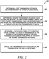
- FIG. 2 is an example flowchart 200 illustrating the operation of a wireless communication device, such as the UE 110, according to a possible embodiment.
- a first transmission occasion and a first priority of a first uplink channel can be determined.
- the first uplink channel can be a first physical uplink channel.
- the first uplink channel can include URLLC data and/or URLLC UCI.
- the UE can transmit/communicate URLLC data/UCI on/via the first uplink channel.
- the first uplink channel can carry URLLC data/UCI.
- a second transmission occasion and a second priority of a second uplink channel can be determined.
- the second uplink channel can be a second physical uplink channel.
- the first priority can be higher than the second priority.
- the first transmission occasion can at least partially overlap in time with the second transmission occasion.
- the second transmission occasion can start earlier than the first transmission occasion.
- a URLLC PUSCH/PUCCH can be equivalent to a high priority uplink channel carrying high priority traffic.
- a non-URLLC PUSCH/PUCCH can be equivalent to a low priority uplink channel carrying low priority traffic.
- a particular symbol of the second uplink channel to cancel the transmission of the second uplink channel can be determined.
- a DCI format including scheduling information for the first uplink channel can be detected and the particular symbol can be determined at least based on timing related to detecting the DCI format.
- the transmission of the second uplink channel from the particular symbol can be cancelled.
- Cancelling the transmission of the second uplink channel from the particular symbol can include stopping the transmission of the second uplink channel from the particular symbol.
- the particular symbol may not be a beginning symbol of the second uplink channel.
- the transmission of the second uplink channel can be stopped after it has already started.
- a start time of the particular symbol can be not later than a start time of the first transmission occasion.
- the particular symbol may not be a beginning symbol of the second uplink channel.
- the UE may not be able to perform simultaneous transmissions of the first and second uplink channels.
- cancellation of the second uplink channel may not be later than the start time of the first transmission occasion.
- the particular symbol can be determined based on a PUSCH timing capability. If the first uplink channel is dynamically scheduled via a PDCCH carrying the DCI format, the start time of cancellation can be determined based on the timing of DCI detection and the PUSCH timing capability.
- the first uplink channel can be a PUCCH carrying first HARQ-ACK information.
- the second uplink channel can be a PUSCH carrying at least second HARQ-ACK information.
- the second HARQ-ACK information can be multiplexed with the first HARQ-ACK information in the first uplink channel.
- embodiments can provide for multiple HARQ-ACK transmissions within a slot.
- a number of resource blocks used for transmitting the PUCCH transmission comprising the first HARQ-ACK information and the second HARQ-ACK information can be larger than a number of resource blocks used for transmitting the PUCCH transmission comprising only the first HARQ-ACK information.
- the number of resource blocks for the PUCCH transmission can be determined based on UCI payload size. For example, the number of resource blocks for the PUCCH transmission can increase with a larger payload size.
- the first HARQ-ACK information can have higher priority than the second HARQ-ACK information.
- the first HARQ-ACK can be a URLLC HARQ-ACK and the second HARQ-ACK can be a non-URLLC HARQ-ACK.
- an indication can be received.
- the indication can indicate to multiplex the second HARQ-ACK information with the first HARQ-ACK information in the first uplink channel.
- the network entity can indicate to the UE whether to multiplex second HARQ-ACK information in the first PUCCH.
- a determination can be made as to whether the UE is in a power-limited condition.
- the second HARQ-ACK information can be multiplexed by multiplexing the second HARQ-ACK information with the first HARQ-ACK information in the first uplink channel in response to determining that the UE is not in the power-limited condition.
- the number of RBs for the first uplink channel may increase if the second HARQ-ACK is multiplexed in the first uplink channel.
- the larger number of RBs for an uplink transmission can require higher transmit power than the smaller number of RBs for the uplink transmission. If the UE is in a power-limited condition, such as when the required transmit power is higher than the max configured power, increasing the number of RBs may degrade demodulation performance. If the UE is not in power-limited condition, such as when the required transmit power is lower than the max configured power, increasing the number of RBs may not degrade demodulation performance.
- the UE can include the first and second HARQ-ACK information in the first PUCCH and can transmit the first PUCCH.
- the UE may not transmit or can cancel the PUSCH transmission.
- the UE can perform this implementation if the UE is not in power-limited condition and accordingly, can transmit the first PUCCH with increased number of resource blocks.
- the particular symbol can be determined based on a number of symbols during a time duration between a start time of the first transmission occasion and an end time of the second transmission occasion.
- the UE can cancel, such as not transmit, the non-URLLC PUSCH/PUCCH transmission, starting from a symbol where the URLLC PUCCH resource transmission starts.
- the UE can perform this implementation if a duration between the start of the URLLC PUCCH and the end of the non-URLLC PUSCH/PUCCH transmission is shorter than a certain threshold value, such as x, percentage of the non-URLLC PUSCH/PUCCH duration or y number of symbols.
- a time interval of the particular symbol can include a start time of the first transmission occasion if the number of symbols is less than a threshold value.
- the second uplink channel can include a plurality of frequency hops.
- Each of the plurality of frequency hops can include a set of self-decodable coded HARQ-ACK bits. For example, if frequency hopping for the non-URLLC PUSCH/PUCCH is enabled and if the time-domain overlapping URLLC PUCCH/PUSCH is within one or a couple of hops of the non-URLLC PUSCH/PUCCH, the UE can transmit a hop of the non-URLLC PUSCH/PUCCH that does not overlap with the URLLC PUCCH/PUSCH.
- cancelling the transmission of the second uplink channel can include cancelling a transmission of a first at least one frequency hop of the second uplink channel.
- a third transmission occasion of the first at least one frequency hop can overlap in time with the first transmission occasion.
- a second at least one frequency hop of the second uplink channel can be transmitted.
- a fourth transmission occasion of the second at least one frequency hop may not overlap in time with the first transmission occasion.
- FIG. 3 is an example block diagram of an apparatus 300, such as the UE 110, the network entity 120, or any other wireless communication device disclosed herein, according to a possible embodiment.
- the apparatus 300 can include a housing 310, a controller 320 coupled to the housing 310, audio input and output circuitry 330 coupled to the controller 320, a display 340 coupled to the controller 320, a memory 350 coupled to the controller 320, a user interface 360 coupled to the controller 320, a transceiver 370 coupled to the controller 320, at least one antenna 375 coupled to the transceiver 370, and a network interface 380 coupled to the controller 320.
- the apparatus 300 may not necessarily include all of the illustrated elements for different embodiments of the present disclosure.
- the apparatus 300 can perform the methods described in all the embodiments.
- the display 340 can be a viewfinder, a Liquid Crystal Display (LCD), a Light Emitting Diode (LED) display, an Organic Light Emitting Diode (OLED) display, a plasma display, a projection display, a touch screen, or any other device that displays information.
- the transceiver 370 can be one or more transceivers that can include a transmitter and/or a receiver.
- the audio input and output circuitry 330 can include a microphone, a speaker, a transducer, or any other audio input and output circuitry.
- the user interface 360 can include a keypad, a keyboard, buttons, a touch pad, a joystick, a touch screen display, another additional display, or any other device useful for providing an interface between a user and an electronic device.
- the network interface 380 can be a Universal Serial Bus (USB) port, an Ethernet port, an infrared transmitter/receiver, an IEEE 1394 port, a wireless transceiver, a WLAN transceiver, or any other interface that can connect an apparatus to a network, device, and/or computer and that can transmit and receive data communication signals.
- USB Universal Serial Bus
- the memory 350 can include a Random-Access Memory (RAM), a Read Only Memory (ROM), an optical memory, a solid-state memory, a flash memory, a removable memory, a hard drive, a cache, or any other memory that can be coupled to an apparatus.
- RAM Random-Access Memory
- ROM Read Only Memory
- optical memory a solid-state memory
- flash memory a flash memory
- removable memory a removable memory
- hard drive a hard drive
- cache or any other memory that can be coupled to an apparatus.
- the apparatus 300 or the controller 320 may implement any operating system, such as Microsoft Windows ® , UNIX ® , LINUX ® , Android TM , or any other operating system.
- Apparatus operation software may be written in any programming language, such as C, C++, Java, or Visual Basic, for example.
- Apparatus software may also run on an application framework, such as, for example, a Java ® framework, a .NET ® framework, or any other application framework.
- the software and/or the operating system may be stored in the memory 350, elsewhere on the apparatus 300, in cloud storage, and/or anywhere else that can store software and/or an operating system.
- the apparatus 300 or the controller 320 may also use hardware to implement disclosed operations.
- the controller 320 may be any programmable processor.
- the controller 320 may perform some or all of the disclosed operations. For example, at least some operations can be performed using cloud computing and the controller 320 may perform other operations. At least some operations can also be performed computer executable instructions executed by at least one computer processor. Disclosed embodiments may also be implemented on a general-purpose or a special purpose computer, a programmed microprocessor or microprocessor, peripheral integrated circuit elements, an application-specific integrated circuit or other integrated circuits, hardware/electronic logic circuits, such as a discrete element circuit, a programmable logic device, such as a programmable logic array, field programmable gate-array, or the like. In general, the controller 320 may be any controller or processor device or devices capable of operating an apparatus and implementing the disclosed embodiments. Some or all of the additional elements of the apparatus 300 can also perform some or all of the operations of the disclosed embodiments.
- the apparatus 300 can perform the methods and operations of the disclosed embodiments.
- the transceiver 370 can transmit and receive signals, including data signals and control signals that can include respective data and control information.
- the controller 320 can generate and process the transmitted and received signals and information.
- the transceiver 370 can communicate on a wireless communication network.
- the controller 320 can determine a first transmission occasion and a first priority of a first uplink channel.
- the first uplink channel can include URLLC data and/or URLLC uplink control information.
- the controller 320 can determine a second transmission occasion and a second priority of a second uplink channel.
- the first priority can be higher than the second priority.
- the first transmission occasion can at least partially overlap in time with the second transmission occasion.
- the second transmission occasion can start earlier than the first transmission occasion.
- the controller 320 can determine a particular symbol of the second uplink channel to cancel a transmission of the second uplink channel.
- the controller 320 can cancel the transmission of the second uplink channel from the particular symbol.
- cancelling the transmission of the second uplink channel from the particular symbol can include stopping the transmission of the second uplink channel from the particular symbol.
- the particular symbol can be not a beginning symbol of the second uplink channel.
- a start time of the particular symbol can be no later than a start time of the first transmission occasion.
- the particular symbol may not be a beginning symbol of the second uplink channel.
- the controller 320 can detect a downlink control information format including scheduling information for the first uplink channel, and the particular symbol can be determined at least based on timing related to detecting the downlink control information format. According to a possible embodiment, the particular symbol is determined based on a physical uplink shared channel timing capability.
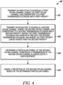
- FIG. 4 is an example flowchart 400 illustrating the operation of a wireless communication device, such as the network entity 120, according to a possible embodiment.
- an indication to schedule a first uplink channel can be transmitted.
- the first uplink channel can correspond to a first transmission occasion and a first priority.
- an indication to schedule a second uplink channel can be transmitted.
- the second uplink channel can correspond to a second transmission occasion and a second priority.
- the first transmission occasion can overlap in time with the second transmission occasion.
- the first priority can be higher than the second priority.
- a particular symbol of the second uplink channel from which a transmission of the second uplink channel is cancelled by a user equipment can be determined based on the first transmission occasion overlapping in time with the second transmission occasion.
- a reception of the second uplink channel can be cancelled based on the determined particular symbol.
- it can be up to network entity implementation when the network entity exactly cancels reception of the second uplink channel.
- the network entity can cease the reception of the second uplink channel from the particular symbol.
- the network entity can cease the reception of the second uplink channel before the particular symbol.
- the first uplink channel can include at least one of URLLC data and URLLC uplink control information.
- the first transmission occasion can partially overlap in time with the second transmission occasion and the second transmission occasion can start earlier than the first transmission occasion.
- the user equipment can stop transmission of the second uplink channel from the particular symbol, where the particular symbol may not be a beginning symbol of the second uplink channel.
- a start time of the particular symbol can be no later than a start time of the first transmission occasion.
- the indication to schedule the first uplink channel can be a DCI format including scheduling information for the first uplink channel, where the particular symbol can be determined at least based on timing related to transmitting the DCI format.
- the particular symbol can be determined based on a PUSCH timing capability for the UE.
- the first uplink channel can be a PUCCH carrying first HARQ-ACK information
- the second uplink channel can be a PUSCH carrying at least second HARQ-ACK information
- the first and second HARQ-ACK information can be received in the first uplink channel.
- the first HARQ-ACK information can have higher priority than the second HARQ-ACK information.
- an indication can be transmitted.
- the indication can indicate to multiplex the second HARQ-ACK information with the first HARQ-ACK information in the first uplink channel.
- a determination can be made as to whether the UE is in a power-limited condition.
- Receiving the first and second HARQ-ACK information can include receiving the first and second HARQ-ACK information in the first uplink channel in response to determining that the UE is not in the power-limited condition.
- the particular symbol can be determined based on a number of symbols during a time duration between a start time of the first transmission occasion and an end time of the second transmission occasion.
- a time interval of the particular symbol can include a start time of the first transmission occasion if the number of symbols is less than a threshold value.
- the second uplink channel can include a plurality of frequency hops, where each of the plurality of frequency hops can include a set of self-decodable coded HARQ-ACK bits.
- cancelling the reception of the second uplink channel can include cancelling a reception of a first at least one frequency hop of the second uplink channel, where a third transmission occasion of the first at least one frequency hop can overlap in time with the first transmission occasion.
- a second at least one frequency hop of the second uplink channel can be received, where a fourth transmission occasion of the second at least one frequency hop may not overlap in time with the first transmission occasion.
- the non-power limited UE can include the first and second HARQ-ACK information in the first PUCCH and transmits the first PUCCH. The UE may not transmit, or can cancel, the non-URLLC PUSCH transmission.
- the UE may not be in power-limited condition and accordingly, can transmit the first PUCCH with an increased number of resource blocks. If the UE is in power-limited condition, the UE can transmit the first PUCCH with the first HARQ-ACK information but without including the second HARQ-ACK information. To avoid the ambiguity between a network entity and the UE, the UE can determine whether to include the second HARQ-ACK information or not in the first PUCCH based on the latest reported power headroom report.
- the coded HARQ-ACK bits can be partitioned in a self-decodable manner and each set of the self-decodable HARQ-ACK channel bits can be transmitted in each frequency hop of the PUSCH.
- the part of PUSCH transmission e.g. a first hop or a second hop
- a part of HARQ-ACK information can still be transmitted.
- a method can be performed in a UE.
- the method can include receiving downlink shared channel data that comprises URLLC data.
- the method can include determining a first transmission occasion to transmit a PUCCH transmission comprising at least first HARQ-ACK information in response to receiving the downlink shared channel data.
- the method can include receiving scheduling information for an uplink shared channel transmission that does not comprise URLLC data at a second transmission occasion, where the uplink shared channel can include a second HARQ-ACK information, and where the first transmission occasion can overlap with the second transmission occasion.
- the method can include determining to not transmit or to cancel the uplink shared channel transmission in response to the first transmission occasion overlapping with the second transmission occasion.
- the method can include determining whether the UE is in power-limited condition.
- the method can include, in response to determining the UE is not power-limited, transmitting the first PUCCH transmission including the first HARQ-ACK information and the second HARQ-ACK information.
- the method can include, in response to determining the UE is in power-limited condition, transmitting the first PUCCH transmission including only the first HARQ-ACK information.
- the number of resources used for transmitting the first PUCCH transmission can include the first HARQ-ACK information and the second HARQ-ACK information can be larger than the number of resources used for transmitting the first PUCCH transmission including only the first HARQ-ACK information.
- a method can be performed in a UE.
- the method can include receiving a first codeword including a transport block associated with a first TCI state in a first transmission occasion.
- the method can include receiving a second codeword including the transport block associated with a second TCI state in a second transmission occasion, where the second transmission occasion can overlap with the first transmission occasion.
- the method can include determining HARQ-ACK feedback information in response to receiving the first codeword and the second codeword.
- the method can include transmitting at least one preferred TCI state for retransmission of the transport block in the HARQ-ACK feedback information in response to determining a NACK for the transport block.
- the first codeword can be transmitted from a first TRP and the second codeword can be transmitted for a second TRP.
- the method can include determining the preferred TCI state among the first TCI state and second TCI state based on link quality on the received first codeword and second codeword, respectively.
- the link quality can be based on one or more of a Signal to Interference plus Noise Ratio (SINR), a reference signal received power, a channel quality metric, a Log-Likelihood Ratio (LLR), and/or Mean Mutual Information (MMIB) associated with the codeword.
- SINR Signal to Interference plus Noise Ratio
- LLR Log-Likelihood Ratio
- MMIB Mean Mutual Information
- controllers, flowcharts, and modules may also be implemented on a general purpose or special purpose computer, a programmed microprocessor or microcontroller and peripheral integrated circuit elements, an integrated circuit, a hardware electronic or logic circuit such as a discrete element circuit, a programmable logic device, or the like.
- any device on which resides a finite state machine capable of implementing the flowcharts shown in the figures may be used to implement the processor functions of this disclosure.
Landscapes
- Engineering & Computer Science (AREA)
- Signal Processing (AREA)
- Computer Networks & Wireless Communication (AREA)
- Mobile Radio Communication Systems (AREA)
- Time-Division Multiplex Systems (AREA)
Applications Claiming Priority (3)
| Application Number | Priority Date | Filing Date | Title |
|---|---|---|---|
| US201962828463P | 2019-04-02 | 2019-04-02 | |
| PCT/IB2020/053036 WO2020202000A1 (en) | 2019-04-02 | 2020-03-31 | Method and apparatus for cancelling transmission based on overlapping transmission occasions |
| EP20718786.5A EP3949189B1 (de) | 2019-04-02 | 2020-03-31 | Verfahren und vorrichtung zur unterdrückung der übertragung auf der grundlage von überlappenden übertragungsgelegenheiten |
Related Parent Applications (2)
| Application Number | Title | Priority Date | Filing Date |
|---|---|---|---|
| EP20718786.5A Division-Into EP3949189B1 (de) | 2019-04-02 | 2020-03-31 | Verfahren und vorrichtung zur unterdrückung der übertragung auf der grundlage von überlappenden übertragungsgelegenheiten |
| EP20718786.5A Division EP3949189B1 (de) | 2019-04-02 | 2020-03-31 | Verfahren und vorrichtung zur unterdrückung der übertragung auf der grundlage von überlappenden übertragungsgelegenheiten |
Publications (2)
| Publication Number | Publication Date |
|---|---|
| EP4358453A2 true EP4358453A2 (de) | 2024-04-24 |
| EP4358453A3 EP4358453A3 (de) | 2024-06-26 |
Family
ID=70285741
Family Applications (2)
| Application Number | Title | Priority Date | Filing Date |
|---|---|---|---|
| EP20718786.5A Active EP3949189B1 (de) | 2019-04-02 | 2020-03-31 | Verfahren und vorrichtung zur unterdrückung der übertragung auf der grundlage von überlappenden übertragungsgelegenheiten |
| EP24160098.0A Pending EP4358453A3 (de) | 2019-04-02 | 2020-03-31 | Verfahren und vorrichtung zur unterdrückung der übertragung auf der basis überlappender übertragungsgelegenheiten |
Family Applications Before (1)
| Application Number | Title | Priority Date | Filing Date |
|---|---|---|---|
| EP20718786.5A Active EP3949189B1 (de) | 2019-04-02 | 2020-03-31 | Verfahren und vorrichtung zur unterdrückung der übertragung auf der grundlage von überlappenden übertragungsgelegenheiten |
Country Status (6)
| Country | Link |
|---|---|
| US (3) | US11212821B2 (de) |
| EP (2) | EP3949189B1 (de) |
| KR (1) | KR20210147025A (de) |
| CN (2) | CN113661668B (de) |
| BR (1) | BR112021019822A2 (de) |
| WO (1) | WO2020202000A1 (de) |
Cited By (1)
| Publication number | Priority date | Publication date | Assignee | Title |
|---|---|---|---|---|
| US12273911B2 (en) | 2019-04-02 | 2025-04-08 | Lenovo (Singapore) Pte. Ltd. | Method and apparatus for cancelling transmission based on overlapping transmission occasions |
Families Citing this family (28)
| Publication number | Priority date | Publication date | Assignee | Title |
|---|---|---|---|---|
| CN111865539B (zh) * | 2019-04-30 | 2022-12-06 | 大唐移动通信设备有限公司 | 一种上行信道传输方法、终端及基站 |
| EP4011011B1 (de) * | 2019-08-05 | 2025-07-09 | ZTE Corporation | Systeme und verfahren zur bestimmung eines rückkopplungscodebuchs |
| EP4014592B1 (de) * | 2019-08-15 | 2025-07-16 | ZTE Corporation | Systeme und verfahren zur übertragung eines signals |
| US11576228B2 (en) * | 2019-08-27 | 2023-02-07 | Qualcomm Incorporated | Uplink preemption indication on multiplexed uplink channels |
| US12207252B2 (en) * | 2019-10-04 | 2025-01-21 | Lg Electronics Inc. | Method for monitoring uplink cancellation instruction, user equipment, apparatus, computer-readable storage medium, method for transmitting uplink cancellation instruction, and base station |
| US11510085B2 (en) * | 2019-10-18 | 2022-11-22 | Qualcomm Incorporated | Channel state information configuration and reporting for ultra reliable low latency communication |
| US11611981B2 (en) | 2019-10-18 | 2023-03-21 | Qualcomm Incorporated | UE feedback of content processing time for bi-directional traffic |
| WO2021093124A1 (en) | 2019-12-31 | 2021-05-20 | Zte Corporation | Systems and methods for determining information indicative of cancelation |
| CN111901882B (zh) * | 2020-01-17 | 2025-05-30 | 中兴通讯股份有限公司 | 信道冲突处理方法、装置、设备和存储介质 |
| CN115039361A (zh) * | 2020-02-10 | 2022-09-09 | 索尼集团公司 | 电信装置和方法 |
| EP4104565A4 (de) * | 2020-02-13 | 2023-11-08 | Qualcomm Incorporated | Überlappung einer dynamischen uplink-berechtigung mit konfigurierter uplink-übertragung |
| US11849434B2 (en) * | 2020-03-18 | 2023-12-19 | Qualcomm Incorporated | Preempting, overwriting, or canceling symbols in a slot format indicator allocation |
| US11601977B2 (en) * | 2020-04-03 | 2023-03-07 | Qualcomm Incorporated | Techniques for collision prioritization based on physical layer priority |
| JP7516549B2 (ja) * | 2020-04-10 | 2024-07-16 | 華為技術有限公司 | 情報送信方法、情報受信方法並びに関連する装置及びデバイス |
| EP4133860B1 (de) * | 2020-04-17 | 2025-04-02 | Guangdong Oppo Mobile Telecommunications Corp., Ltd. | Vorrichtung und verfahren zur übertragung davon |
| US11758551B2 (en) * | 2020-04-24 | 2023-09-12 | Qualcomm Incorporated | Cancellation of transmission occasions |
| US11723023B2 (en) | 2020-05-07 | 2023-08-08 | Samsung Electronics Co., Ltd. | System and method for managing collisions in multiple-transmission-and-reception-points communications |
| WO2021226885A1 (zh) * | 2020-05-13 | 2021-11-18 | 北京小米移动软件有限公司 | 上行控制信息发送方法和装置 |
| CN116210307B (zh) * | 2020-08-07 | 2025-09-30 | 中兴通讯股份有限公司 | 用于下行链路控制信息传输的方法和系统 |
| CN114126049A (zh) * | 2020-08-25 | 2022-03-01 | Oppo广东移动通信有限公司 | 无线通信方法和设备 |
| WO2022082803A1 (zh) * | 2020-10-23 | 2022-04-28 | 华为技术有限公司 | 上行控制信息传输方法及装置 |
| CN114765865A (zh) * | 2021-01-14 | 2022-07-19 | 索尼公司 | 用于无线通信的电子设备和方法、计算机可读存储介质 |
| CN115190599B (zh) * | 2021-04-02 | 2025-09-19 | 大唐移动通信设备有限公司 | 一种上行信道的传输方法及装置 |
| WO2023011290A1 (zh) * | 2021-08-06 | 2023-02-09 | 华为技术有限公司 | 信道处理方法及装置 |
| US20250133592A1 (en) * | 2022-02-11 | 2025-04-24 | Apple Inc. | Management Prioritization for Subsequent Small Data Transmission in Inactive Mode |
| CN117296418A (zh) * | 2022-02-21 | 2023-12-26 | 中兴通讯股份有限公司 | 用于在子带全双工系统中解决方向冲突的方法、设备和系统 |
| CN120153731A (zh) * | 2022-11-04 | 2025-06-13 | 苹果公司 | 用于解决与不同网络相关的操作的时间窗口之间的冲突的方法和设备 |
| WO2025071182A1 (ko) * | 2023-09-25 | 2025-04-03 | 엘지전자 주식회사 | 무선 통신 시스템에서 신호를 송수신하는 방법 및 장치 |
Family Cites Families (28)
| Publication number | Priority date | Publication date | Assignee | Title |
|---|---|---|---|---|
| US20170223695A1 (en) * | 2016-02-03 | 2017-08-03 | Lg Electronics Inc. | Method and apparatus for transmitting an uplink channel in a wireless communication system |
| WO2017171398A1 (en) * | 2016-03-29 | 2017-10-05 | Lg Electronics Inc. | Method and apparatus for configuring frame structure for new radio access technology in wireless communication system |
| US11252717B2 (en) * | 2016-09-02 | 2022-02-15 | Huawei Technologies Co., Ltd. | Co-existence of latency tolerant and low latency communications |
| US20180176937A1 (en) * | 2016-12-16 | 2018-06-21 | Asustek Computer Inc. | Method and apparatus of handling multiple uplink resource collisions in a wireless communication system |
| US11166262B2 (en) * | 2017-01-05 | 2021-11-02 | FG Innovation Company Limited | Long physical uplink control channel (PUCCH) design for 5th generation (5G) new radio (NR) |
| CA3049107A1 (en) | 2017-01-05 | 2018-07-12 | FG Innovation Company Limited | Long physical uplink control channel (pucch) design for 5th generation (5g) new radio (nr) |
| US11044739B2 (en) * | 2017-01-06 | 2021-06-22 | Convida Wireless | Mechanisms for efficient access and transmission in NR |
| KR102248077B1 (ko) * | 2017-01-15 | 2021-05-04 | 엘지전자 주식회사 | 무선 통신 시스템에서, harq-ack 신호를 전송하는 방법 및 이를 위한 장치 |
| US10225826B2 (en) * | 2017-03-24 | 2019-03-05 | Nokia Technologies Oy | Transmission of uplink control information for multiple control channel format lengths |
| US11974364B2 (en) * | 2017-05-03 | 2024-04-30 | Apple Inc. | Handling collision for mini-slot-based and slot-based transmission |
| CN116032447A (zh) * | 2017-06-14 | 2023-04-28 | Idac控股公司 | 可靠控制信令 |
| US10582454B2 (en) * | 2017-09-27 | 2020-03-03 | Ofinno, Llc | Power control for uplink control channel |
| US11297503B2 (en) * | 2017-11-29 | 2022-04-05 | Telefonaktiebolaget Lm Ericsson (Publ) | Security for positioning without ciphering |
| US10873966B2 (en) * | 2018-01-02 | 2020-12-22 | Samsung Electronics Co., Ltd. | Signaling of control information in a communication system |
| KR102616557B1 (ko) * | 2018-02-13 | 2023-12-26 | 삼성전자 주식회사 | 무선 통신 시스템에서 데이터 및 제어 정보 송수신 방법 및 장치 |
| JP7100694B2 (ja) * | 2018-04-05 | 2022-07-13 | エルジー エレクトロニクス インコーポレイティド | 無線通信システムにおいて無線信号の送受信方法及び装置 |
| JP7121796B2 (ja) * | 2018-05-10 | 2022-08-18 | エルジー エレクトロニクス インコーポレイティド | 無線通信システムにおいて無線信号の送受信方法及び装置 |
| US10880895B2 (en) * | 2018-05-27 | 2020-12-29 | Brian Gordaychik | Variable length downlink control information formats for next generation radio technologies |
| US11432369B2 (en) * | 2018-06-19 | 2022-08-30 | Apple Inc. | Reference signal and control information processing in 5G-NR wireless systems |
| EP3694134B1 (de) * | 2018-08-09 | 2022-02-16 | LG Electronics Inc. | Verfahren und vorrichtung zum senden und empfangen eines drahtlossignals in einem drahtloskommunikationssystem |
| US11357017B2 (en) * | 2019-01-11 | 2022-06-07 | Lenovo (Singapore) Pte. Ltd. | Method and apparatus for transmitting a high priority uplink transmission |
| CA3071723A1 (en) * | 2019-02-07 | 2020-08-07 | Comcast Cable Communications, Llc | Pre-emption of signal transmission |
| WO2020167033A1 (ko) * | 2019-02-14 | 2020-08-20 | 엘지전자 주식회사 | Nr v2x의 사이드링크 동기 신호 블록의 전송 |
| WO2020165881A1 (en) * | 2019-02-15 | 2020-08-20 | Lenovo (Singapore) Pte. Ltd. | Method and apparatus for selectively applying the power adjustment of a transmit power control command |
| EP3925365B1 (de) * | 2019-03-15 | 2025-12-10 | Samsung Electronics Co., Ltd. | Verfahren und vorrichtung zur prioritätsbasierten steuerung und dateninformationsübertragung in einem drahtlosen kommunikationssystem |
| US11381346B2 (en) * | 2019-04-02 | 2022-07-05 | Intel Corporation | Prioritization of services for control and data transmission for new radio systems |
| US11212821B2 (en) | 2019-04-02 | 2021-12-28 | Lenovo (Singapore) Pte. Ltd. | Method and apparatus for cancelling transmission based on overlapping transmission occasions |
| US11838083B2 (en) * | 2020-07-15 | 2023-12-05 | Qualcomm Incorporated | Sequence based uplink control channel coexistence |
-
2020
- 2020-03-30 US US16/833,674 patent/US11212821B2/en active Active
- 2020-03-31 WO PCT/IB2020/053036 patent/WO2020202000A1/en not_active Ceased
- 2020-03-31 EP EP20718786.5A patent/EP3949189B1/de active Active
- 2020-03-31 KR KR1020217035824A patent/KR20210147025A/ko active Pending
- 2020-03-31 BR BR112021019822A patent/BR112021019822A2/pt unknown
- 2020-03-31 EP EP24160098.0A patent/EP4358453A3/de active Pending
- 2020-03-31 CN CN202080027184.4A patent/CN113661668B/zh active Active
- 2020-03-31 CN CN202410406555.XA patent/CN118199820B/zh active Active
-
2021
- 2021-11-18 US US17/529,291 patent/US11690095B2/en active Active
-
2023
- 2023-05-12 US US18/197,015 patent/US12273911B2/en active Active
Cited By (1)
| Publication number | Priority date | Publication date | Assignee | Title |
|---|---|---|---|---|
| US12273911B2 (en) | 2019-04-02 | 2025-04-08 | Lenovo (Singapore) Pte. Ltd. | Method and apparatus for cancelling transmission based on overlapping transmission occasions |
Also Published As
| Publication number | Publication date |
|---|---|
| EP3949189B1 (de) | 2024-05-01 |
| US20220078814A1 (en) | 2022-03-10 |
| CN118199820B (zh) | 2025-04-08 |
| BR112021019822A2 (pt) | 2021-12-07 |
| WO2020202000A1 (en) | 2020-10-08 |
| US20230284260A1 (en) | 2023-09-07 |
| EP3949189C0 (de) | 2024-05-01 |
| CN113661668B (zh) | 2024-04-26 |
| US11212821B2 (en) | 2021-12-28 |
| US12273911B2 (en) | 2025-04-08 |
| EP3949189A1 (de) | 2022-02-09 |
| CN118199820A (zh) | 2024-06-14 |
| CN113661668A (zh) | 2021-11-16 |
| US11690095B2 (en) | 2023-06-27 |
| EP4358453A3 (de) | 2024-06-26 |
| KR20210147025A (ko) | 2021-12-06 |
| US20200322971A1 (en) | 2020-10-08 |
Similar Documents
| Publication | Publication Date | Title |
|---|---|---|
| US12273911B2 (en) | Method and apparatus for cancelling transmission based on overlapping transmission occasions | |
| US20250317936A1 (en) | Method and apparatus for transmitting information on an uplink channel | |
| US10574421B2 (en) | Method and apparatus for scheduling uplink transmissions with reduced latency | |
| EP3412095B1 (de) | Verfahren und vorrichtung zum senden von planungsanforderungen mit reduzierter latenzzeit | |
| US10813150B2 (en) | Method and apparatus for scheduling uplink transmissions with reduced latency | |
| KR102216025B1 (ko) | 감소된 레이턴시로 버퍼 상태 보고들을 송신하기 위한 방법 및 장치 | |
| EP3412077B1 (de) | Verfahren und vorrichtung zur übertragung unterschiedlicher leistungsreserveberichte, basierend auf unterschiedlichen sendezeitintervalllängen | |
| KR102431721B1 (ko) | 업링크 전송들이 적어도 하나의 심벌 지속기간 동안 시간상 오버랩할 때 업링크 전력 제어를 위한 방법 및 장치 | |
| EP3411996B1 (de) | Verfahren und vorrichtung zur zeitplanung von uplink-übertragungen mit reduzierter latenz |
Legal Events
| Date | Code | Title | Description |
|---|---|---|---|
| PUAI | Public reference made under article 153(3) epc to a published international application that has entered the european phase |
Free format text: ORIGINAL CODE: 0009012 |
|
| STAA | Information on the status of an ep patent application or granted ep patent |
Free format text: STATUS: THE APPLICATION HAS BEEN PUBLISHED |
|
| AC | Divisional application: reference to earlier application |
Ref document number: 3949189 Country of ref document: EP Kind code of ref document: P |
|
| AK | Designated contracting states |
Kind code of ref document: A2 Designated state(s): AL AT BE BG CH CY CZ DE DK EE ES FI FR GB GR HR HU IE IS IT LI LT LU LV MC MK MT NL NO PL PT RO RS SE SI SK SM TR |
|
| REG | Reference to a national code |
Ref country code: DE Ref legal event code: R079 Free format text: PREVIOUS MAIN CLASS: H04L0001182900 Ipc: H04L0001000000 |
|
| PUAL | Search report despatched |
Free format text: ORIGINAL CODE: 0009013 |
|
| AK | Designated contracting states |
Kind code of ref document: A3 Designated state(s): AL AT BE BG CH CY CZ DE DK EE ES FI FR GB GR HR HU IE IS IT LI LT LU LV MC MK MT NL NO PL PT RO RS SE SI SK SM TR |
|
| RIC1 | Information provided on ipc code assigned before grant |
Ipc: H04L 1/1829 20230101ALI20240521BHEP Ipc: H04L 5/00 20060101ALI20240521BHEP Ipc: H04W 72/00 20230101ALI20240521BHEP Ipc: H04L 1/00 20060101AFI20240521BHEP |
|
| STAA | Information on the status of an ep patent application or granted ep patent |
Free format text: STATUS: REQUEST FOR EXAMINATION WAS MADE |
|
| 17P | Request for examination filed |
Effective date: 20241212 |