EP4357524B1 - Flammenschutzvorrichtung für einen brenner und trockentrommel mit einer derartigen flammenschutzvorrichtung - Google Patents
Flammenschutzvorrichtung für einen brenner und trockentrommel mit einer derartigen flammenschutzvorrichtung Download PDFInfo
- Publication number
- EP4357524B1 EP4357524B1 EP23202571.8A EP23202571A EP4357524B1 EP 4357524 B1 EP4357524 B1 EP 4357524B1 EP 23202571 A EP23202571 A EP 23202571A EP 4357524 B1 EP4357524 B1 EP 4357524B1
- Authority
- EP
- European Patent Office
- Prior art keywords
- protection device
- drying drum
- flame protection
- slats
- longitudinal axis
- Prior art date
- Legal status (The legal status is an assumption and is not a legal conclusion. Google has not performed a legal analysis and makes no representation as to the accuracy of the status listed.)
- Active
Links
Images


Classifications
-
- F—MECHANICAL ENGINEERING; LIGHTING; HEATING; WEAPONS; BLASTING
- F26—DRYING
- F26B—DRYING SOLID MATERIALS OR OBJECTS BY REMOVING LIQUID THEREFROM
- F26B11/00—Machines or apparatus for drying solid materials or objects with movement which is non-progressive
- F26B11/02—Machines or apparatus for drying solid materials or objects with movement which is non-progressive in moving drums or other mainly-closed receptacles
- F26B11/028—Arrangements for the supply or exhaust of gaseous drying medium for direct heat transfer, e.g. perforated tubes, annular passages, burner arrangements, dust separation, combined direct and indirect heating
-
- F—MECHANICAL ENGINEERING; LIGHTING; HEATING; WEAPONS; BLASTING
- F26—DRYING
- F26B—DRYING SOLID MATERIALS OR OBJECTS BY REMOVING LIQUID THEREFROM
- F26B25/00—Details of general application not covered by group F26B21/00 or F26B23/00
- F26B25/06—Chambers, containers, or receptacles
- F26B25/14—Chambers, containers, receptacles of simple construction
- F26B25/16—Chambers, containers, receptacles of simple construction mainly closed, e.g. drum
-
- E—FIXED CONSTRUCTIONS
- E01—CONSTRUCTION OF ROADS, RAILWAYS, OR BRIDGES
- E01C—CONSTRUCTION OF, OR SURFACES FOR, ROADS, SPORTS GROUNDS, OR THE LIKE; MACHINES OR AUXILIARY TOOLS FOR CONSTRUCTION OR REPAIR
- E01C19/00—Machines, tools or auxiliary devices for preparing or distributing paving materials, for working the placed materials, or for forming, consolidating, or finishing the paving
- E01C19/02—Machines, tools or auxiliary devices for preparing or distributing paving materials, for working the placed materials, or for forming, consolidating, or finishing the paving for preparing the materials
- E01C19/05—Crushing, pulverising or disintegrating apparatus; Aggregate screening, cleaning, drying or heating apparatus; Dust-collecting arrangements specially adapted therefor
-
- E—FIXED CONSTRUCTIONS
- E01—CONSTRUCTION OF ROADS, RAILWAYS, OR BRIDGES
- E01C—CONSTRUCTION OF, OR SURFACES FOR, ROADS, SPORTS GROUNDS, OR THE LIKE; MACHINES OR AUXILIARY TOOLS FOR CONSTRUCTION OR REPAIR
- E01C19/00—Machines, tools or auxiliary devices for preparing or distributing paving materials, for working the placed materials, or for forming, consolidating, or finishing the paving
- E01C19/02—Machines, tools or auxiliary devices for preparing or distributing paving materials, for working the placed materials, or for forming, consolidating, or finishing the paving for preparing the materials
- E01C19/10—Apparatus or plants for premixing or precoating aggregate or fillers with non-hydraulic binders, e.g. with bitumen, with resins, i.e. producing mixtures or coating aggregates otherwise than by penetrating or surface dressing; Apparatus for premixing non-hydraulic mixtures prior to placing or for reconditioning salvaged non-hydraulic compositions
- E01C19/1013—Plant characterised by the mode of operation or the construction of the mixing apparatus; Mixing apparatus
-
- F—MECHANICAL ENGINEERING; LIGHTING; HEATING; WEAPONS; BLASTING
- F23—COMBUSTION APPARATUS; COMBUSTION PROCESSES
- F23M—CASINGS, LININGS, WALLS OR DOORS SPECIALLY ADAPTED FOR COMBUSTION CHAMBERS, e.g. FIREBRIDGES; DEVICES FOR DEFLECTING AIR, FLAMES OR COMBUSTION PRODUCTS IN COMBUSTION CHAMBERS; SAFETY ARRANGEMENTS SPECIALLY ADAPTED FOR COMBUSTION APPARATUS; DETAILS OF COMBUSTION CHAMBERS, NOT OTHERWISE PROVIDED FOR
- F23M9/00—Baffles or deflectors for air or combustion products; Flame shields
-
- F—MECHANICAL ENGINEERING; LIGHTING; HEATING; WEAPONS; BLASTING
- F26—DRYING
- F26B—DRYING SOLID MATERIALS OR OBJECTS BY REMOVING LIQUID THEREFROM
- F26B23/00—Heating arrangements
- F26B23/02—Heating arrangements using combustion heating
-
- F—MECHANICAL ENGINEERING; LIGHTING; HEATING; WEAPONS; BLASTING
- F26—DRYING
- F26B—DRYING SOLID MATERIALS OR OBJECTS BY REMOVING LIQUID THEREFROM
- F26B25/00—Details of general application not covered by group F26B21/00 or F26B23/00
- F26B25/06—Chambers, containers, or receptacles
- F26B25/08—Parts thereof
-
- F—MECHANICAL ENGINEERING; LIGHTING; HEATING; WEAPONS; BLASTING
- F26—DRYING
- F26B—DRYING SOLID MATERIALS OR OBJECTS BY REMOVING LIQUID THEREFROM
- F26B3/00—Drying solid materials or objects by processes involving the application of heat
- F26B3/02—Drying solid materials or objects by processes involving the application of heat by convection, i.e. heat being conveyed from a heat source to the materials or objects to be dried by a gas or vapour, e.g. air
- F26B3/04—Drying solid materials or objects by processes involving the application of heat by convection, i.e. heat being conveyed from a heat source to the materials or objects to be dried by a gas or vapour, e.g. air the gas or vapour circulating over or surrounding the materials or objects to be dried
Definitions
- the invention relates to a flame protection device for a burner and a drying drum with such a flame protection device.
- DE 10 2017 212 046 A1 discloses a plant for producing asphalt.
- a flame tube is arranged in a drying drum to protect the burner flame.
- a lamella recuperator is arranged in the drying drum as part of a flow control unit, which serves for the targeted combustion of pollutant components in the exhaust gas and/or in secondary exhaust gases.
- the invention is based on the object of improving a combustion process in a drying drum and, in particular, of carrying it out undisturbed.
- the object is achieved by a flame protection device having the features of claim 1 and by a drying drum according to claim 8.
- the essence of the invention is that in a flame protection device several throwing plates are arranged in the circumferential direction with respect to a central longitudinal axis the flame protection device.
- the throwing plates guarantee advantageous conveyance of the material to be dried in the drying drum.
- the flame protection device with the throwing plates is arranged in particular in an area of the drying drum in which a burner flame of the burner is arranged.
- the throwing plates guarantee reliable transport of the material. Undesirable contact of the material to be dried with the burner flame is avoided in particular. This can prevent disruption of the combustion process and undesirable cooling as a result of disruption of the flame.
- the efficiency of the combustion process is improved.
- the emission of undesirable exhaust gases in particular the proportion of unburned hydrocarbons (C total ), in particular carbon monoxide (CO) and/or carbon dioxide (CO 2 ) is reduced.
- the process is ecologically and economically improved.
- the combustion process is more sustainable.
- the flame protection device in particular the throwing plates, and/or the drying drum are thermally protected from the burner flame and in particular from thermal radiation from the burner flame.
- the material cools the flame protection device.
- the throwing plates are arranged in particular at a distance from one another in the circumferential direction with respect to the central longitudinal axis.
- the throwing plates are in particular attached to an inner wall of the drying drum.
- a separate holding element is used in particular to attach the throwing plates to the inner wall of the drying drum, which is in particular directly attached, in particular welded, to the inner wall of the drying drum.
- the inner wall of the drying drum is partially exposed between two throwing plates arranged adjacent to each other in the circumferential direction.
- the throwing plates are oriented in particular parallel to the central longitudinal axis.
- At least one lamella holder and in particular two lamella holders are detachably attached to the throwing plates.
- Slats can be attached to the lamella holders as part of the flame protection device.
- the lamellas enable an additional improvement in the combustion process.
- the fact that the lamella holders and thus the lamellas are detachably attached to the throwing plates makes it easier to retrofit the lamellas in the drying drum.
- the lamellas are wearing parts with an average service life of less than a year due to the high thermal load.
- the detachable attachment makes replacing the lamellas easier. Maintenance times are reduced. The overall efficiency of the system is therefore increased.
- the material used to replace worn lamellas is reduced.
- the throwing plates are made of a heat-resistant material, in particular of a heat-resistant structural steel, which is designated according to DIN EN 10028-2 with the material number 1.5415 or with the material abbreviation 16Mo3.
- the throwing plates are in particular each designed as sheet metal components and in particular each made from a flat sheet metal cut, in particular by bending.
- the sheet thickness s of the throwing plate is in particular between 5 mm and 10 mm, in particular between 7 mm and 9 mm and in particular 8 mm.
- the lamella holders are made of a heat-resistant material, in particular of a tenitic chromium-nickel steel, in particular with the material number 1.4841 according to DIN EN 10095.
- This material has a thermal expansion coefficient ⁇ between 15 ⁇ 10- 6 and 20 ⁇ 10- 6 , in particular 17 ⁇ 10- 6 and 18 ⁇ 10- 6 , in a relevant temperature range of 300°C to 700°C and in particular in a range of 350°C to 650°C, in particular in a range of 380°C to 620° C and in particular in a range of 400° C to 600° C .
- Other chromium-nickel steels are also possible, in particular with the material number 1.4828 or 1.4742, which is known under the trade name Sicromal 10.
- the flame protection device is used for a burner, which in particular generates an open burner flame.
- the burner can be operated with fossil fuels, in particular fossil energy sources such as natural gas, liquid gas, heating oil and/or coal dust. Additionally or alternatively, the burner can be operated with renewable fuels such as wood pellets, wood dust, methane generated from biogas and/or hydrogen gas.
- the burner is used in particular to heat a drying drum, which is used in particular to heat material in an asphalt plant.
- the flame protection device in such a drying drum enables an increased addition of recycled material, in particular old asphalt granulate.
- the production of asphalt is therefore more sustainable because the use of raw materials is reduced.
- the drying drum ensures uncomplicated and robust installation in the drying drum.
- a flame protection device ensures improved material transport.
- the shovel-like throwing plates have an L-shaped contour, in particular in a plane perpendicular to the central longitudinal axis.
- the throwing plates are arranged on the inner wall of the drying drum in such a way that a material receiving chamber is formed between the throwing plates and the inner wall of the drying drum, which enables reliable material entrainment. In particular, the risk of an undesirable material veil forming in the area of the burner flame is reduced. In particular, such a material veil is reliably prevented.
- the throwing plate is arranged on the inner wall of the drying drum with a, in particular short, web. This web forms a rear wall of the throwing plate and forms a rear end of the throwing plate in relation to the direction of rotation of the drying drum.
- the throwing plate is open opposite the rear wall. This opening is used in particular to receive and/or discharge material to be dried, which is conveyed along the material conveying direction.
- the opening extends in particular along the full width of the throwing plate. This means that the throwing plate is designed without a front wall opposite the rear wall. It is conceivable to design the throwing plate with a front wall that extends at least partially along the width of the throwing plate.
- the material intake channel is designed to be open, particularly along the central longitudinal axis.
- a flame protection device enables flexible and reliable fastening of the throwing plates.
- Fastening strips in particular each have an insertion slot.
- the insertion slot has a slot width that essentially corresponds to the sheet thickness of the throwing plate.
- the slot width can be slightly smaller than the sheet thickness of the throwing plate in order to improve fastening by clamping.
- the throwing plate is held in the fastening strips in particular in a form-fitting and/or force-fitting manner.
- the insertion slot extends in particular essentially along the circumferential direction.
- the throwing plates are each pushed into at least one and in particular into several fastening strips.
- the fastening strips are in particular fastened to the inner wall of the drying drum in such a way that the insertion slots are arranged in alignment along the central longitudinal axis.
- the fastening strips make it possible to fasten the throwing plates, in particular detachably and variably adjustable with regard to the angle of attack relative to the inner wall of the drying drum.
- a flame protection device simplifies a robust fastening of the slat holder to the throwing plate.
- the slat holder can advantageously be securely fastened to a rear wall of the throwing plate using a screw connection.
- the slat holder extends in particular in a transverse direction and in particular radially with respect to the central longitudinal axis. The radially spaced attachment of the slats with respect to the throwing plates is thereby simplified.
- a flame protection device enables the flexible and advantageous orientation of the slat holder with respect to the slat.
- the slat holder which is designed in particular as a flat sheet metal cut, can be oriented transversely and in particular perpendicularly to the central longitudinal axis and can be detachably attached to the throwing plate in this orientation.
- a bracket is particularly L-shaped, in particular as an angle profile with holes for a screw connection.
- a flame protection device enables an uncomplicated formation of a material receiving channel which extends in particular along several throwing plates, in particular arranged one behind the other along the central longitudinal axis.
- the material receiving channel enables reliable material conveyance along the material conveying direction through the drying drum.
- the throwing plates are arranged in particular in alignment with one another with respect to the central longitudinal axis.
- a cover element according to claim 7 prevents the heated material from unintentionally escaping from the material receiving channel, in particular from the front.
- the material is released in particular via the throwing plates to a material outlet from the drying drum.
- a cover element is attached in particular to the front of the throwing plate, in particular oriented perpendicular to the central longitudinal axis.
- the cover element is in particular welded to the throwing plate.
- a drying drum according to claim 8 enables the advantageous implementation of the combustion process with increased efficiency and/or reduced exhaust emissions.
- the drying drum enables the use of increased amounts of old asphalt granulate in asphalt production.
- the replacement of worn lamellae is simplified by means of the lamella holders detachably attached to the throwing plates.
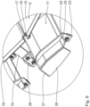
- the arrangement designated as a whole with 1, comprises a drying drum 2, on the front of which a burner 3 is arranged.
- the arrangement 1 is in particular part of an asphalt plant in which asphalt material is produced.
- white mineral in particular is heated in a countercurrent process.
- a material flow direction 4 and a heat propagation direction 5 are oriented opposite to one another.
- the drying drum 2 can also be operated in a cocurrent process.
- other materials in particular rock and/or old asphalt material, can also be heated in the drying drum 2.
- the burner 3 generates a burner flame 6 which extends at least partially into the drying drum 2.
- a flame protection device is arranged in the drying drum 2, in particular in the area of the burner flame 6.
- the flame protection device has a central longitudinal axis 7 which coincides with an axis of rotation 8 of the drying drum 2.
- the flame protection device has several lamellae 9, which are arranged in the circumferential direction 10 with respect to the central longitudinal axis 7.
- the Slats 9 ensure that thermally heated air remains within the peripheral arrangement 10 and does not inadvertently flow outwards, in particular in a radial direction relative to the central longitudinal axis 7.
- the slats 9 prevent material heated in the drying drum 2 from inadvertently falling into the burner flame 6 and thus adversely affecting the burning process.
- the flame protection device has throwing plates 11.
- the throwing plates 11 are arranged concentrically with respect to the central longitudinal axis 7, in particular with respect to the slats 9 in the drying drum 2.
- the throwing plates 11 are arranged in the flame area of the drying drum 2.
- the throwing plates 11 enable the material to be dried to be entrained, i.e. material to be conveyed along the material conveying direction 4.
- the throwing plates 11 are designed in particular in such a way that a material veil in the drying drum 2 is prevented when the material is entrained. This means that when the drying drum 2 rotates about the axis of rotation 8, the material is held in the radial direction in the throwing plates 11 and in particular only an axial material conveyance takes place along the material conveying direction 4.
- the throwing plates 11 reliably prevent the material from trickling down from top to bottom in the drying drum 2 due to gravity and forming a material veil.
- both the throwing plates 11 themselves and the drying drum 2 are thermally protected from the burner flame 6 and/or the heat radiation emitted by the burner flame 6. The material thus cools the internals and the drying drum 2.
- Slat holders 12 are attached to the throwing plates 11 and serve to hold the slats 9.
- the slat holders 12 are attached to the throwing plates 11.
- the slat holders 12 extend in particular perpendicular to the central longitudinal axis 7 and in particular radially.
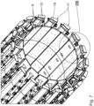
- the flame protection device has a baffle 13.
- the baffle 13 is arranged along the central longitudinal axis 7 at an axial distance from the slats 9.
- the baffle 13 is disk-like and in particular essentially circular and is fastened in the drying drum 2 with at least one baffle fastening element 14.
- the baffle 13 prevents the burner flame 6 from accidentally breaking through into a further throwing plate area of the drying drum 2 arranged behind the baffle 13. A material veil is deliberately created in this further throwing plate area.
- the baffle 13 prevents material damage.
- a circumferential arrangement of the slats 9 comprises eighteen individual slats 9.
- the slats 9 are functionally identical and in particular have identical dimensions. Depending on the size to be formed, i.e. the clear width of the circumferential arrangement, more or fewer than eighteen slats 9 can be used to form a circumferential arrangement.
- circumferential arrangements are arranged one behind the other along the central longitudinal axis 7. More or less than four circumferential orders can be arranged one behind the other.
- the individual circumferential arrangements are in particular designed identically. It is also conceivable that the circumferential arrangements have different diameters and/or are designed conically at least in sections.
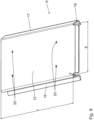
- the slats 9 each have a flame protection section 15 facing inwards, i.e. towards the burner flame 6.
- the flame protection section 15 has a rectangular contour with a length L and a width B.
- the length L of the slat 9 is greater than its width B.
- the slats 9 are arranged next to one another in the circumferential arrangement with respect to their longitudinal direction. In the circumferential arrangement, the slats 9 are oriented with their longitudinal direction parallel to the central longitudinal axis 7.
- a contour formed by the slats 9 in a plane perpendicular to the central longitudinal axis 7 is constant along the central longitudinal axis 7. Because the flame protection sections 15 are flat, the peripheral arrangement has an inner contour in a plane perpendicular to the central longitudinal axis 7 which is essentially polygonal.
- the slats 9 are made from a sheet metal blank made from material number 1.4841.
- the sheet thickness s is in particular in a range from 3 mm to 10 mm and in particular between 5 mm and 7 mm.
- the slat 9 has sealing elements 16, 17 formed in one piece on its longitudinal edges.
- the sealing elements 16, 17 are designed as bevels.
- the sealing elements 16, 17 are designed to correspond to one another.
- the sealing elements 16, 17 form lateral sealing elements on the slats 9.
- the sealing elements 16, 17 form sealing strips.
- the sealing elements 16, 17 are designed such that the slats 9 are arranged alternately with the sealing elements 16, 17 in the circumferential order.
- a first sealing element 16 essentially has an S-contour.
- the S-contour extends in particular from the flame protection section 15 in a direction facing away from the burner flame 6.
- the first sealing element 16 forms a concave receptacle.
- the second sealing element 17 has a contour that corresponds to a rounded arrowhead.
- the second sealing element 17 forms a convex-shaped projection.
- the convex outer contour of the second sealing element 17 corresponds to the concave inner contour of the first sealing element 16.
- the second sealing element 17 of a lamella 9 can be arranged on the first sealing element 16 of an adjacent lamella 9.
- This arrangement of adjacent lamellas 9 with the sealing elements 16, 17 arranged one inside the other is particularly in Fig. 4 and 6
- Corresponding sealing elements 16, 17 of adjacent lamellae 9 engage with one another, so that at most a thin air gap remains, which is in any case smaller than the sheet thickness s of the lamellae 9.
- the maximum gap width is at most 0.5 xs, in particular at most 0.3 xs, in particular at most 0.2 xs and in particular 0.1 x s.
- the circumferential arrangement is designed to be self-supporting. This prevents the lamellae 9 from accidentally separating from one another.
- the sealing elements 16, 17 ensure that the adjacent lamellae 9 engage behind one another in such a way that the circumferential arrangement is designed to be stable in the radial direction relative to the central longitudinal axis 7.
- the slats 9 have a front bevel 18 on a transverse edge that is oriented in the width direction.
- the front bevel 18 is inclined downwards at an angle relative to the plane formed by the flame protection section 15. This angle of inclination is at most 30°, in particular at most 20°, in particular at most 15° and in particular at most 10°.
- the bevel 18 functions as an insertion tab that can be inserted in particular into the respective peripheral arrangement arranged in front of it.
- the slats 9 arranged one behind the other along the central longitudinal axis 7 are aligned.
- Each slat 9 is held by at least one slat holder 19 and, according to the embodiment shown, by two slat holders 19.
- the slat holder 19 is made from a flat sheet metal blank and in particular has a strip-like contour.
- the slat holder 19 is in particular made from the same material as the slat 9.
- the sheet metal thickness of the slat holder is in particular between 8 mm and 15 mm and in particular between 10 mm and 12 mm.
- the slat holder 19 has projections, in particular two retaining pins, which are arranged in particular on the front side.
- the retaining pins can engage in recesses 20 which are arranged on the flame protection section 15.
- the recesses 20 are designed in particular as punched-through holes.
- the slat 9 is in particular supported or placed on the slat holder 19.
- the recesses 20 serve as an assembly aid for the slat holder 19 of the slat 9.
- the slat 9 is detachably attached to the slat holder 19.
- the assembly of the peripheral arrangement is thereby simplified.
- the slat holders 19 can also be permanently attached to the slat 9, in particular welded on.
- At least one lamella 31 per circumferential arrangement is designed differently with respect to the recesses 20.
- This lamella is referred to as the end lamella 31.
- the associated end lamella holders 32 for the end lamella 31 do not have any protruding retaining pins, but rather a bent support tab 21, which is particularly suitable in Fig. 5 is shown.
- the circumferential arrangement is formed by arranging slats 9 in a row adjacent to one another in the circumferential direction 10 and placing them on the respective slat holders 19.
- the slats 19 are stabilized by the interlocking sealing elements 16, 17 on the one hand and by the engagement of the retaining pins in the recesses 20 on the other.
- the final slat 31 is inserted axially as the last slat, i.e. in a direction parallel to the central longitudinal axis 7, and in doing so comes into engagement with the two adjacent slats 9.
- the sealing elements 16, 17 ensure an undercut in the radial direction between adjacent slats 9 and 9, 31.
- the final slat 31, which is mounted last, is attached to the support tabs 21, in particular welded.
- the slats 9 By using the slat holders 19, it is possible for the slats 9 to be arranged in the drying drum 2 at a radial distance from an inner wall 22 of the drying drum 2.
- the slats 9 form an installation that is arranged at a distance from the inner wall 22 and is aligned concentrically to the central longitudinal axis 7.
- the peripheral arrangement is essentially designed in a ring-like manner with the polygonal inner contour.
- the peripheral arrangement is firmly connected to the drying drum 2. When the drying drum 2 rotates, the peripheral arrangement rotates with it.
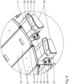
- the throwing plates 11 are arranged offset radially outwards in the radial direction relative to the axis of rotation 8.
- the throwing plates 11 are arranged on the inner wall 22 of the drying drum 2.
- retaining tabs 23 can be attached, in particular welded, directly to the inner wall 22.
- a fastening strip 24 is detachably attached, in particular screwed, to each of the retaining tabs 23.
- each throwing plate 11 is held by several, in particular three, fastening strips 24, wherein the fastening strips 24 are identical and arranged at a distance from one another along the central longitudinal axis 7.
- the fastening strips 24 each have a slot-shaped receptacle 25 into which the throwing plates 11 are inserted.
- the throwing plate 11 is designed like a shovel and has an L-shaped contour in a plane oriented perpendicular to the central longitudinal axis 7.
- the throwing plate 11 is arranged on the inner wall 22 of the drying drum 2 in such a way that the short web of the "L" extends essentially parallel to the inner wall 22 of the drying drum 2. Essentially means that the throwing plate 11 has no curvature on the inner wall 22 of the drying drum 2.
- the throwing plate 11 can be designed with bevels.
- a material receiving chamber is formed between the throwing plate 11 and the inner wall 22 of the drying drum 2, which has an open rectangular contour in a plane perpendicular to the central longitudinal axis 7. The rectangle is open on a side opposite the short web of the "L".
- the material receiving chamber is also open in particular along the central longitudinal axis 7. It is possible, that these front sides of the material receiving chamber are closed by separate cover elements 26. In particular, the front side of the material receiving chamber facing the material outlet of the drying drum 2 is closed by the cover element 26.
- the cover element 26 is attached to the throwing plate 11, in particular welded thereto.
- the throwing plates 11 arranged one behind the other along the central longitudinal axis 7 are arranged in a continuous manner to one another, i.e. they abut one another at the front.
- the throwing plates 11 form the material receiving channel extending over several throwing plates 11.
- the design of the throwing plates 11 ensures that the material to be heated is reliably carried along in the drying drum 2, but no material veil is formed in the area of the slats 9.
- the short web of the "L” forms a rear wall 27 of the throwing plate 11.
- the slat holders 19 of the slats 9 are detachably attached to the rear wall 27.
- a holding bracket 28 is used for this purpose, which is designed in particular as an L-profile and enables sheet metal sections oriented at 90° to one another to be screwed together.
- the slat holders 19 are detachably attached to the throwing plates 11. Retrofitting the slat holders 19 and/or the slats 9 held thereon is simplified. In particular, it is not necessary for the slats 9 to be attached to the inner wall itself using the slat holders 19. The assembly and disassembly effort is reduced.
- each lamella 9 there is at least one throwing plate 11 for each lamella 9.
- Corresponding lamellas 9 and throwing plates 11 are arranged in alignment in the radial direction with respect to the central longitudinal axis 7.
- the baffle wall 13 is arranged axially spaced from the slats 9, which is particularly Fig. 3 is shown.
- the impact wall 13 is made up of several, according to the embodiment shown, three, identical impact wall segments 29.
- the impact wall segments 29 each have a disk section and a one-piece impact wall fastening element 14 attached to it.
- the disk sections are each designed like a third of a circular disk, i.e. with an opening angle of 120° in relation to the central longitudinal axis 7.
- flange strips are bent on the parallel wall segments 29 and screwed together.
- the impact wall segments 29 are attached to corresponding throwing plates 11 by means of the impact wall fastening elements 14 and by means of a retaining tab 30 provided for this purpose.
Landscapes
- Engineering & Computer Science (AREA)
- General Engineering & Computer Science (AREA)
- Mechanical Engineering (AREA)
- Structural Engineering (AREA)
- Civil Engineering (AREA)
- Architecture (AREA)
- Life Sciences & Earth Sciences (AREA)
- Chemical & Material Sciences (AREA)
- Combustion & Propulsion (AREA)
- Microbiology (AREA)
- Sustainable Development (AREA)
- Physics & Mathematics (AREA)
- Thermal Sciences (AREA)
- Drying Of Solid Materials (AREA)
- Road Paving Machines (AREA)
Priority Applications (1)
| Application Number | Priority Date | Filing Date | Title |
|---|---|---|---|
| EP24203920.4A EP4462054A3 (de) | 2022-10-20 | 2023-10-10 | Flammenschutzvorrichtung für einen brenner, wurfblech für eine derartige flammenschutzvorrichtung und trockentrommel mit einer derartigen flammenschutzvorrichtung |
Applications Claiming Priority (1)
| Application Number | Priority Date | Filing Date | Title |
|---|---|---|---|
| DE102022211109.5A DE102022211109B4 (de) | 2022-10-20 | 2022-10-20 | Flammenschutzvorrichtung für einen Brenner, Wurfblech für eine derartige Flammenschutzvorrichtung und Trockentrommel mit einer derartigen Flammenschutzvorrichtung |
Related Child Applications (2)
| Application Number | Title | Priority Date | Filing Date |
|---|---|---|---|
| EP24203920.4A Division EP4462054A3 (de) | 2022-10-20 | 2023-10-10 | Flammenschutzvorrichtung für einen brenner, wurfblech für eine derartige flammenschutzvorrichtung und trockentrommel mit einer derartigen flammenschutzvorrichtung |
| EP24203920.4A Division-Into EP4462054A3 (de) | 2022-10-20 | 2023-10-10 | Flammenschutzvorrichtung für einen brenner, wurfblech für eine derartige flammenschutzvorrichtung und trockentrommel mit einer derartigen flammenschutzvorrichtung |
Publications (2)
| Publication Number | Publication Date |
|---|---|
| EP4357524A1 EP4357524A1 (de) | 2024-04-24 |
| EP4357524B1 true EP4357524B1 (de) | 2025-02-26 |
Family
ID=88316042
Family Applications (2)
| Application Number | Title | Priority Date | Filing Date |
|---|---|---|---|
| EP23202571.8A Active EP4357524B1 (de) | 2022-10-20 | 2023-10-10 | Flammenschutzvorrichtung für einen brenner und trockentrommel mit einer derartigen flammenschutzvorrichtung |
| EP24203920.4A Pending EP4462054A3 (de) | 2022-10-20 | 2023-10-10 | Flammenschutzvorrichtung für einen brenner, wurfblech für eine derartige flammenschutzvorrichtung und trockentrommel mit einer derartigen flammenschutzvorrichtung |
Family Applications After (1)
| Application Number | Title | Priority Date | Filing Date |
|---|---|---|---|
| EP24203920.4A Pending EP4462054A3 (de) | 2022-10-20 | 2023-10-10 | Flammenschutzvorrichtung für einen brenner, wurfblech für eine derartige flammenschutzvorrichtung und trockentrommel mit einer derartigen flammenschutzvorrichtung |
Country Status (8)
| Country | Link |
|---|---|
| US (1) | US20240230230A9 (pl) |
| EP (2) | EP4357524B1 (pl) |
| DE (1) | DE102022211109B4 (pl) |
| DK (1) | DK4357524T3 (pl) |
| ES (1) | ES3031416T3 (pl) |
| FI (1) | FI4357524T3 (pl) |
| PL (1) | PL4357524T3 (pl) |
| PT (1) | PT4357524T (pl) |
Families Citing this family (1)
| Publication number | Priority date | Publication date | Assignee | Title |
|---|---|---|---|---|
| DE102022211109B4 (de) | 2022-10-20 | 2024-06-27 | Benninghoven Zweigniederlassung Der Wirtgen Mineral Technologies Gmbh | Flammenschutzvorrichtung für einen Brenner, Wurfblech für eine derartige Flammenschutzvorrichtung und Trockentrommel mit einer derartigen Flammenschutzvorrichtung |
Family Cites Families (17)
| Publication number | Priority date | Publication date | Assignee | Title |
|---|---|---|---|---|
| US4293228A (en) * | 1979-10-29 | 1981-10-06 | Cmi Corporation | Drum for an asphalt mixing apparatus |
| US4406584A (en) * | 1980-08-07 | 1983-09-27 | Stepp William J | Vertical axis windmill with multistage feathering of blades and safety storm control |
| US6185842B1 (en) * | 1990-10-17 | 2001-02-13 | Gencor Industries, Inc. | Apparatus and methods for controlling the temperature of exhaust gases in a drum mixer |
| US5083382A (en) * | 1990-12-11 | 1992-01-28 | Gencor Industries Inc. | Adjustable flights with dams for rotary dryers |
| DE4243264C2 (de) * | 1992-12-19 | 1997-03-20 | Deutag Ag | Verfahren zum Betreiben eines Drehrohrofens zum Trocknen und Mischen von rieselfähigem Material |
| US5515620A (en) * | 1994-11-10 | 1996-05-14 | Gencor Industries, Inc. | Method and apparatus of rotatable drum dryer with flights releasably secured in different orientations |
| US5638606A (en) * | 1996-03-06 | 1997-06-17 | Gala Industries, Inc. | Spider and lifter assembly for centrifugal pellet dryer |
| US6290152B1 (en) * | 1996-12-02 | 2001-09-18 | Environmental Reprocessing, Inc. | Method for recycling asphalt material |
| US5765293A (en) * | 1997-03-12 | 1998-06-16 | Haden, Inc. | Method for processing paint sludge |
| US8296968B2 (en) * | 2003-06-13 | 2012-10-30 | Charles Hensley | Surface drying apparatus and method |
| US9382672B2 (en) * | 2010-12-06 | 2016-07-05 | Astec, Inc. | Apparatus and method for dryer performance optimization system |
| US8863404B1 (en) * | 2010-12-06 | 2014-10-21 | Astec, Inc. | Apparatus and method for dryer performance optimization system |
| US9301535B1 (en) * | 2014-07-21 | 2016-04-05 | Solar Equipment Corporation | Equipment and methods to dry sugar beet pulp and other products |
| EP3265217B1 (en) * | 2015-03-05 | 2020-04-29 | Gala Industries, Inc. | Tumbler systems and methods |
| DE102017212046B4 (de) | 2016-09-16 | 2025-03-20 | Benninghoven Zweigniederlassung Der Wirtgen Mineral Technologies Gmbh | Weißmineral-Trockentrommel zum Erwärmen von Weißmineral zum Herstellen von Asphalt sowie Anlage mit einer derartigen Weißmineral-Trockentrommel |
| US12134864B2 (en) * | 2021-03-25 | 2024-11-05 | e5 Engineers, LLC | Flight for asphalt rotary dryer |
| DE102022211109B4 (de) | 2022-10-20 | 2024-06-27 | Benninghoven Zweigniederlassung Der Wirtgen Mineral Technologies Gmbh | Flammenschutzvorrichtung für einen Brenner, Wurfblech für eine derartige Flammenschutzvorrichtung und Trockentrommel mit einer derartigen Flammenschutzvorrichtung |
-
2022
- 2022-10-20 DE DE102022211109.5A patent/DE102022211109B4/de active Active
-
2023
- 2023-10-10 ES ES23202571T patent/ES3031416T3/es active Active
- 2023-10-10 EP EP23202571.8A patent/EP4357524B1/de active Active
- 2023-10-10 DK DK23202571.8T patent/DK4357524T3/da active
- 2023-10-10 FI FIEP23202571.8T patent/FI4357524T3/fi active
- 2023-10-10 EP EP24203920.4A patent/EP4462054A3/de active Pending
- 2023-10-10 PL PL23202571.8T patent/PL4357524T3/pl unknown
- 2023-10-10 PT PT232025718T patent/PT4357524T/pt unknown
- 2023-10-18 US US18/489,113 patent/US20240230230A9/en active Pending
Also Published As
| Publication number | Publication date |
|---|---|
| EP4462054A3 (de) | 2024-12-25 |
| EP4357524A1 (de) | 2024-04-24 |
| FI4357524T3 (fi) | 2025-06-03 |
| DE102022211109B4 (de) | 2024-06-27 |
| PT4357524T (pt) | 2025-05-29 |
| DK4357524T3 (da) | 2025-05-19 |
| PL4357524T3 (pl) | 2025-07-07 |
| US20240230230A9 (en) | 2024-07-11 |
| DE102022211109A1 (de) | 2024-04-25 |
| ES3031416T3 (en) | 2025-07-08 |
| US20240133628A1 (en) | 2024-04-25 |
| EP4462054A2 (de) | 2024-11-13 |
Similar Documents
| Publication | Publication Date | Title |
|---|---|---|
| EP4357710B1 (de) | Trockentrommel mit flammenschutzvorrichtung | |
| DE102022202605B4 (de) | Flammschutz-Vorrichtung und Trockentrommel mit einer derartigen Flammschutz-Vorrichtung | |
| EP4357524B1 (de) | Flammenschutzvorrichtung für einen brenner und trockentrommel mit einer derartigen flammenschutzvorrichtung | |
| EP2992270B1 (de) | Hitzeschild | |
| EP3296462B1 (de) | Anlage und verfahren zum herstellen von asphalt | |
| EP2326879B1 (de) | Hinterlüftete feuerfeste wand, insbesondere für einen verbrennungsofen | |
| EP0195360B1 (de) | Atmosphärischer Gasbrenner | |
| EP4717977A1 (de) | Flammenschutzvorrichtung für einen brenner, lamelle für eine derartige flammenschutzvorrichtung und trockentrommel mit einer derartigen flammenschutzvorrichtung | |
| DE102015205975A1 (de) | Umführungs-Hitzeschildelement | |
| DE102022005072A1 (de) | Flammenschutzvorrichtung für einen Brenner, Wurfblech für eine derartige Flammenschutzvorrichtung und Trockentrommel mit einer derartigen Flammenschutzvorrichtung | |
| DE102022005139A1 (de) | Flammenschutzvorrichtung für einen Brenner, Lamelle für eine derartige Flammenschutzvorrichtung und Trockentrommel mit einer derartigen Flammenschutzvorrichtung | |
| DE102022005073A1 (de) | Flammenschutzvorrichtung für einen Brenner, Lamelle für eine derartige Flammenschutzvorrichtung und Trockentrommel mit einer derartigen Flammenschutzvorrichtung | |
| DE102008020424A1 (de) | Ölvormischbrenner | |
| DE3535442C2 (pl) | ||
| DE10148686C1 (de) | Brennvorrichtung | |
| EP0209703B1 (de) | Glüheinsatz für Öfen, insbesondere Heizungskessel, sowie Ofen mit einem derartigen Glüheinsatz | |
| EP0532051B1 (de) | Lamellenwärmetauscher | |
| EP0606551B1 (de) | Walzenrost zum Betrieb eines Verbrennungskessels | |
| WO1982000331A1 (fr) | Generateur de gaz chaud | |
| DE102011109970A1 (de) | Gas/Gas-Wärmetauscher | |
| DE9407914U1 (de) | Gußgliederkessel | |
| WO2020200450A1 (de) | Brennkammer für einen heissgaserzeuger einer asphaltproduktionsanlage mit luftleitblechen und verfahen zur befestigung der luftleitbleche | |
| DE8517157U1 (de) | Ofen, insbesondere Heizungskessel | |
| DE3521043A1 (de) | Ofen, insbesondere heizungskessel | |
| DE1968116U (de) | Allgasbrenner fuer heizgase unterschiedlicher brenntechnischer eigenschaften. |
Legal Events
| Date | Code | Title | Description |
|---|---|---|---|
| PUAI | Public reference made under article 153(3) epc to a published international application that has entered the european phase |
Free format text: ORIGINAL CODE: 0009012 |
|
| STAA | Information on the status of an ep patent application or granted ep patent |
Free format text: STATUS: REQUEST FOR EXAMINATION WAS MADE |
|
| 17P | Request for examination filed |
Effective date: 20240315 |
|
| AK | Designated contracting states |
Kind code of ref document: A1 Designated state(s): AL AT BE BG CH CY CZ DE DK EE ES FI FR GB GR HR HU IE IS IT LI LT LU LV MC ME MK MT NL NO PL PT RO RS SE SI SK SM TR |
|
| STAA | Information on the status of an ep patent application or granted ep patent |
Free format text: STATUS: EXAMINATION IS IN PROGRESS |
|
| 17Q | First examination report despatched |
Effective date: 20240502 |
|
| GRAP | Despatch of communication of intention to grant a patent |
Free format text: ORIGINAL CODE: EPIDOSNIGR1 |
|
| STAA | Information on the status of an ep patent application or granted ep patent |
Free format text: STATUS: GRANT OF PATENT IS INTENDED |
|
| INTG | Intention to grant announced |
Effective date: 20241011 |
|
| GRAS | Grant fee paid |
Free format text: ORIGINAL CODE: EPIDOSNIGR3 |
|
| GRAA | (expected) grant |
Free format text: ORIGINAL CODE: 0009210 |
|
| STAA | Information on the status of an ep patent application or granted ep patent |
Free format text: STATUS: THE PATENT HAS BEEN GRANTED |
|
| AK | Designated contracting states |
Kind code of ref document: B1 Designated state(s): AL AT BE BG CH CY CZ DE DK EE ES FI FR GB GR HR HU IE IS IT LI LT LU LV MC ME MK MT NL NO PL PT RO RS SE SI SK SM TR |
|
| REG | Reference to a national code |
Ref country code: GB Ref legal event code: FG4D Free format text: NOT ENGLISH |
|
| REG | Reference to a national code |
Ref country code: CH Ref legal event code: EP |
|
| REG | Reference to a national code |
Ref country code: DE Ref legal event code: R096 Ref document number: 502023000621 Country of ref document: DE |
|
| REG | Reference to a national code |
Ref country code: IE Ref legal event code: FG4D Free format text: LANGUAGE OF EP DOCUMENT: GERMAN |
|
| P01 | Opt-out of the competence of the unified patent court (upc) registered |
Free format text: CASE NUMBER: APP_8932/2025 Effective date: 20250221 |
|
| REG | Reference to a national code |
Ref country code: DK Ref legal event code: T3 Effective date: 20250515 |
|
| REG | Reference to a national code |
Ref country code: NL Ref legal event code: FP |
|
| REG | Reference to a national code |
Ref country code: PT Ref legal event code: SC4A Ref document number: 4357524 Country of ref document: PT Date of ref document: 20250529 Kind code of ref document: T Free format text: AVAILABILITY OF NATIONAL TRANSLATION Effective date: 20250522 |
|
| REG | Reference to a national code |
Ref country code: FI Ref legal event code: FGE |
|
| PG25 | Lapsed in a contracting state [announced via postgrant information from national office to epo] |
Ref country code: RS Free format text: LAPSE BECAUSE OF FAILURE TO SUBMIT A TRANSLATION OF THE DESCRIPTION OR TO PAY THE FEE WITHIN THE PRESCRIBED TIME-LIMIT Effective date: 20250526 |
|
| REG | Reference to a national code |
Ref country code: ES Ref legal event code: FG2A Ref document number: 3031416 Country of ref document: ES Kind code of ref document: T3 Effective date: 20250708 |
|
| REG | Reference to a national code |
Ref country code: LT Ref legal event code: MG9D |
|
| PG25 | Lapsed in a contracting state [announced via postgrant information from national office to epo] |
Ref country code: NO Free format text: LAPSE BECAUSE OF FAILURE TO SUBMIT A TRANSLATION OF THE DESCRIPTION OR TO PAY THE FEE WITHIN THE PRESCRIBED TIME-LIMIT Effective date: 20250526 Ref country code: IS Free format text: LAPSE BECAUSE OF FAILURE TO SUBMIT A TRANSLATION OF THE DESCRIPTION OR TO PAY THE FEE WITHIN THE PRESCRIBED TIME-LIMIT Effective date: 20250626 |
|
| PG25 | Lapsed in a contracting state [announced via postgrant information from national office to epo] |
Ref country code: HR Free format text: LAPSE BECAUSE OF FAILURE TO SUBMIT A TRANSLATION OF THE DESCRIPTION OR TO PAY THE FEE WITHIN THE PRESCRIBED TIME-LIMIT Effective date: 20250226 |
|
| PG25 | Lapsed in a contracting state [announced via postgrant information from national office to epo] |
Ref country code: LV Free format text: LAPSE BECAUSE OF FAILURE TO SUBMIT A TRANSLATION OF THE DESCRIPTION OR TO PAY THE FEE WITHIN THE PRESCRIBED TIME-LIMIT Effective date: 20250226 |
|
| PG25 | Lapsed in a contracting state [announced via postgrant information from national office to epo] |
Ref country code: BG Free format text: LAPSE BECAUSE OF FAILURE TO SUBMIT A TRANSLATION OF THE DESCRIPTION OR TO PAY THE FEE WITHIN THE PRESCRIBED TIME-LIMIT Effective date: 20250226 Ref country code: GR Free format text: LAPSE BECAUSE OF FAILURE TO SUBMIT A TRANSLATION OF THE DESCRIPTION OR TO PAY THE FEE WITHIN THE PRESCRIBED TIME-LIMIT Effective date: 20250527 |
|
| REG | Reference to a national code |
Ref country code: SK Ref legal event code: T3 Ref document number: E 46479 Country of ref document: SK |
|
| PG25 | Lapsed in a contracting state [announced via postgrant information from national office to epo] |
Ref country code: SE Free format text: LAPSE BECAUSE OF FAILURE TO SUBMIT A TRANSLATION OF THE DESCRIPTION OR TO PAY THE FEE WITHIN THE PRESCRIBED TIME-LIMIT Effective date: 20250226 |
|
| PG25 | Lapsed in a contracting state [announced via postgrant information from national office to epo] |
Ref country code: SM Free format text: LAPSE BECAUSE OF FAILURE TO SUBMIT A TRANSLATION OF THE DESCRIPTION OR TO PAY THE FEE WITHIN THE PRESCRIBED TIME-LIMIT Effective date: 20250226 |
|
| PGFP | Annual fee paid to national office [announced via postgrant information from national office to epo] |
Ref country code: PT Payment date: 20250929 Year of fee payment: 3 |
|
| PG25 | Lapsed in a contracting state [announced via postgrant information from national office to epo] |
Ref country code: EE Free format text: LAPSE BECAUSE OF FAILURE TO SUBMIT A TRANSLATION OF THE DESCRIPTION OR TO PAY THE FEE WITHIN THE PRESCRIBED TIME-LIMIT Effective date: 20250226 |
|
| PGFP | Annual fee paid to national office [announced via postgrant information from national office to epo] |
Ref country code: CZ Payment date: 20250926 Year of fee payment: 3 |
|
| PG25 | Lapsed in a contracting state [announced via postgrant information from national office to epo] |
Ref country code: RO Free format text: LAPSE BECAUSE OF FAILURE TO SUBMIT A TRANSLATION OF THE DESCRIPTION OR TO PAY THE FEE WITHIN THE PRESCRIBED TIME-LIMIT Effective date: 20250226 |
|
| REG | Reference to a national code |
Ref country code: DE Ref legal event code: R097 Ref document number: 502023000621 Country of ref document: DE |
|
| PLBE | No opposition filed within time limit |
Free format text: ORIGINAL CODE: 0009261 |
|
| STAA | Information on the status of an ep patent application or granted ep patent |
Free format text: STATUS: NO OPPOSITION FILED WITHIN TIME LIMIT |
|
| PGFP | Annual fee paid to national office [announced via postgrant information from national office to epo] |
Ref country code: AT Payment date: 20260113 Year of fee payment: 3 |
|
| PGFP | Annual fee paid to national office [announced via postgrant information from national office to epo] |
Ref country code: IT Payment date: 20251031 Year of fee payment: 3 Ref country code: FI Payment date: 20251022 Year of fee payment: 3 Ref country code: DK Payment date: 20251023 Year of fee payment: 3 |
|
| PGFP | Annual fee paid to national office [announced via postgrant information from national office to epo] |
Ref country code: FR Payment date: 20251022 Year of fee payment: 3 |
|
| PGFP | Annual fee paid to national office [announced via postgrant information from national office to epo] |
Ref country code: TR Payment date: 20251002 Year of fee payment: 3 |
|
| PGFP | Annual fee paid to national office [announced via postgrant information from national office to epo] |
Ref country code: SK Payment date: 20251007 Year of fee payment: 3 |
|
| PGFP | Annual fee paid to national office [announced via postgrant information from national office to epo] |
Ref country code: ES Payment date: 20251114 Year of fee payment: 3 |
|
| 26N | No opposition filed |
Effective date: 20251127 |
|
| PGFP | Annual fee paid to national office [announced via postgrant information from national office to epo] |
Ref country code: DE Payment date: 20251217 Year of fee payment: 3 |