EP4357178A1 - Vehicle sunroof device and window plate assembly thereof - Google Patents
Vehicle sunroof device and window plate assembly thereof Download PDFInfo
- Publication number
- EP4357178A1 EP4357178A1 EP23179068.4A EP23179068A EP4357178A1 EP 4357178 A1 EP4357178 A1 EP 4357178A1 EP 23179068 A EP23179068 A EP 23179068A EP 4357178 A1 EP4357178 A1 EP 4357178A1
- Authority
- EP
- European Patent Office
- Prior art keywords
- buckling
- plate assembly
- window plate
- buckling groove
- seal
- Prior art date
- Legal status (The legal status is an assumption and is not a legal conclusion. Google has not performed a legal analysis and makes no representation as to the accuracy of the status listed.)
- Withdrawn
Links
Images


Classifications
-
- B—PERFORMING OPERATIONS; TRANSPORTING
- B60—VEHICLES IN GENERAL
- B60J—WINDOWS, WINDSCREENS, NON-FIXED ROOFS, DOORS, OR SIMILAR DEVICES FOR VEHICLES; REMOVABLE EXTERNAL PROTECTIVE COVERINGS SPECIALLY ADAPTED FOR VEHICLES
- B60J10/00—Sealing arrangements
- B60J10/80—Sealing arrangements specially adapted for opening panels, e.g. doors
- B60J10/82—Sealing arrangements specially adapted for opening panels, e.g. doors for movable panels in roofs
-
- B—PERFORMING OPERATIONS; TRANSPORTING
- B60—VEHICLES IN GENERAL
- B60J—WINDOWS, WINDSCREENS, NON-FIXED ROOFS, DOORS, OR SIMILAR DEVICES FOR VEHICLES; REMOVABLE EXTERNAL PROTECTIVE COVERINGS SPECIALLY ADAPTED FOR VEHICLES
- B60J10/00—Sealing arrangements
- B60J10/70—Sealing arrangements specially adapted for windows or windscreens
- B60J10/74—Sealing arrangements specially adapted for windows or windscreens for sliding window panes, e.g. sash guides
- B60J10/76—Sealing arrangements specially adapted for windows or windscreens for sliding window panes, e.g. sash guides for window sashes; for glass run channels
- B60J10/763—Sealing arrangements specially adapted for windows or windscreens for sliding window panes, e.g. sash guides for window sashes; for glass run channels for preventing outward displacement of windows when at high speed
-
- B—PERFORMING OPERATIONS; TRANSPORTING
- B60—VEHICLES IN GENERAL
- B60J—WINDOWS, WINDSCREENS, NON-FIXED ROOFS, DOORS, OR SIMILAR DEVICES FOR VEHICLES; REMOVABLE EXTERNAL PROTECTIVE COVERINGS SPECIALLY ADAPTED FOR VEHICLES
- B60J10/00—Sealing arrangements
- B60J10/15—Sealing arrangements characterised by the material
-
- B—PERFORMING OPERATIONS; TRANSPORTING
- B60—VEHICLES IN GENERAL
- B60J—WINDOWS, WINDSCREENS, NON-FIXED ROOFS, DOORS, OR SIMILAR DEVICES FOR VEHICLES; REMOVABLE EXTERNAL PROTECTIVE COVERINGS SPECIALLY ADAPTED FOR VEHICLES
- B60J10/00—Sealing arrangements
- B60J10/20—Sealing arrangements characterised by the shape
- B60J10/24—Sealing arrangements characterised by the shape having tubular parts
-
- B—PERFORMING OPERATIONS; TRANSPORTING
- B60—VEHICLES IN GENERAL
- B60J—WINDOWS, WINDSCREENS, NON-FIXED ROOFS, DOORS, OR SIMILAR DEVICES FOR VEHICLES; REMOVABLE EXTERNAL PROTECTIVE COVERINGS SPECIALLY ADAPTED FOR VEHICLES
- B60J10/00—Sealing arrangements
- B60J10/30—Sealing arrangements characterised by the fastening means
-
- B—PERFORMING OPERATIONS; TRANSPORTING
- B60—VEHICLES IN GENERAL
- B60J—WINDOWS, WINDSCREENS, NON-FIXED ROOFS, DOORS, OR SIMILAR DEVICES FOR VEHICLES; REMOVABLE EXTERNAL PROTECTIVE COVERINGS SPECIALLY ADAPTED FOR VEHICLES
- B60J10/00—Sealing arrangements
- B60J10/30—Sealing arrangements characterised by the fastening means
- B60J10/34—Sealing arrangements characterised by the fastening means using adhesives
-
- B—PERFORMING OPERATIONS; TRANSPORTING
- B60—VEHICLES IN GENERAL
- B60J—WINDOWS, WINDSCREENS, NON-FIXED ROOFS, DOORS, OR SIMILAR DEVICES FOR VEHICLES; REMOVABLE EXTERNAL PROTECTIVE COVERINGS SPECIALLY ADAPTED FOR VEHICLES
- B60J10/00—Sealing arrangements
- B60J10/70—Sealing arrangements specially adapted for windows or windscreens
-
- B—PERFORMING OPERATIONS; TRANSPORTING
- B60—VEHICLES IN GENERAL
- B60J—WINDOWS, WINDSCREENS, NON-FIXED ROOFS, DOORS, OR SIMILAR DEVICES FOR VEHICLES; REMOVABLE EXTERNAL PROTECTIVE COVERINGS SPECIALLY ADAPTED FOR VEHICLES
- B60J10/00—Sealing arrangements
- B60J10/90—Sealing arrangements specially adapted for non-fixed roofs, e.g. foldable roofs or removable hard-tops
-
- B—PERFORMING OPERATIONS; TRANSPORTING
- B60—VEHICLES IN GENERAL
- B60J—WINDOWS, WINDSCREENS, NON-FIXED ROOFS, DOORS, OR SIMILAR DEVICES FOR VEHICLES; REMOVABLE EXTERNAL PROTECTIVE COVERINGS SPECIALLY ADAPTED FOR VEHICLES
- B60J7/00—Non-fixed roofs; Roofs with movable panels, e.g. rotary sunroofs
- B60J7/0007—Non-fixed roofs; Roofs with movable panels, e.g. rotary sunroofs moveable head-liners, screens, curtains or blinds for ceilings
-
- B—PERFORMING OPERATIONS; TRANSPORTING
- B60—VEHICLES IN GENERAL
- B60J—WINDOWS, WINDSCREENS, NON-FIXED ROOFS, DOORS, OR SIMILAR DEVICES FOR VEHICLES; REMOVABLE EXTERNAL PROTECTIVE COVERINGS SPECIALLY ADAPTED FOR VEHICLES
- B60J7/00—Non-fixed roofs; Roofs with movable panels, e.g. rotary sunroofs
-
- B—PERFORMING OPERATIONS; TRANSPORTING
- B60—VEHICLES IN GENERAL
- B60J—WINDOWS, WINDSCREENS, NON-FIXED ROOFS, DOORS, OR SIMILAR DEVICES FOR VEHICLES; REMOVABLE EXTERNAL PROTECTIVE COVERINGS SPECIALLY ADAPTED FOR VEHICLES
- B60J7/00—Non-fixed roofs; Roofs with movable panels, e.g. rotary sunroofs
- B60J7/02—Non-fixed roofs; Roofs with movable panels, e.g. rotary sunroofs of sliding type, e.g. comprising guide shoes
- B60J7/04—Non-fixed roofs; Roofs with movable panels, e.g. rotary sunroofs of sliding type, e.g. comprising guide shoes with rigid plate-like element or elements, e.g. open roofs with harmonica-type folding rigid panels
- B60J7/043—Sunroofs e.g. sliding above the roof
Definitions
- the present disclosure relates to a vehicle field, especially to a window plate assembly of a vehicle.
- An adhesive strip is often disposed between the vehicle body and a glass frame for a vehicle window of a vehicle body, thus a sealing effect can be achieved through the adhesive strip abutting against the vehicle body or the glass frame to generate an elastic deformation. As such, rainwater or moisture can be prevented from permeating into the vehicle body.
- An adhering method is used to make the adhesive strip be fastened with a glass frame or the vehicle body to ensure a sealing status, or a buckling method is used to make the adhesive strip be easily detached.
- the adhering method allows the adhesive strip to be tightly adhered with the glass frame or the vehicle body to achieve a good sealing effect, but the assembling procedure is complicated (such as requiring steps of cleaning the location to be adhered, preparing an adhesive agent, adhering the adhesive strip, and placing to be dried), and the deteriorated adhesive strip is not easy to be replaced, and a risk of the adhesive strip being loosened is caused.
- the buckling method allows the adhesive strip to be easily detached relative to the vehicle body or the glass frame, but the adhesive strip may not be ensured to tightly adhere with the vehicle body or the glass frame, thus a problem of poor sealing is concerned.
- the present disclosure is to provide a vehicle sunroof device and a window plate assembly thereof, in which a seal is easy to be detached and forms an excellent sealing effect with a window frame.
- the present disclosure provides a window plate assembly, which includes a glass panel, a window frame, and a seal.
- the window frame is disposed at a periphery of the glass panel.
- An outer periphery of the window frame is disposed with a buckling groove and extended with a block flange.
- a planar surface is formed between the buckling groove and the block flange.
- An abutting part is formed at one side of the seal, and a buckling part is extended from the abutting part.
- the buckling part is buckled in the buckling groove to make the abutting part abut against the planar surface and the block flange.
- a buckling direction of the buckling part and the buckling groove is perpendicular to the planar surface.
- the buckling part includes a main body and a latching hook.
- a reserved hook is formed in the buckling groove.
- a cross section of the seal is in a semi-circular shape.
- the window frame has an installing slot, the glass panel is disposed in the installing slot, and the block flange is extended in a direction away from the glass panel.
- an included angle is defined between the block flange and the planar surface, and the included angle is smaller than or equal to 90°.
- a guiding inclined surface is formed at an opening of the buckling groove.
- the seal and the buckling part are a hollow structure.
- a vehicle sunroof device which includes a vehicle body and a window plate assembly.
- the vehicle body has a sunroof seat.
- the window plate assembly is disposed in the sunroof seat and has a glass panel, a window frame, and a seal.
- the glass panel is disposed on the window frame.
- An outer periphery of the window frame is disposed with a buckling groove and extended with a block flange.
- a planar surface is formed between the buckling groove and the block flange.
- the seal has an abutting part and a buckling part extended from the abutting part.
- the buckling part is buckled in the buckling groove to make the abutting part abut against the planar surface and the block flange.
- a buckling direction of the buckling part and the buckling groove is perpendicular to the planar surface.
- the window plate assembly of the present disclosure makes the seal be easily and rapidly detached, and through the block flange and the planar surface abutting against the abutting part of the seal, a sealing status is formed to effectively increase the watertightness.
- the present disclosure provides a vehicle sunroof device and a window plate assembly thereof.
- the vehicle sunroof device includes a vehicle body and a window plate assembly.
- the vehicle body has a sunroof seat (that is, an opening or a window opening) A1 allowing the window plate assembly to be disposed.
- the vehicle body includes a reinforced frame A and a sheet metal C. A top end and lateral sides of the reinforced frame A are covered by the sheet metal C to increase the structural strength via the reinforced frame A.
- the sunroof seat A1 is formed on the reinforced frame A and the sheet metal C allows the window plate assembly of the present disclosure to be disposed, here is not intended to be limiting.
- the vehicle body may only include the sheet plate C.
- the window plate assembly is a moveable sunroof B1 to make at least a part of the sunroof seat A1 be opened or closed, here is not intended to be limiting.
- the window plate assembly may be a fixed window B2 to fix and close the whole or at least a part of the sunroof seat A1.
- the following illustrations is provided for the movable sunroof B1.
- the window plate assembly includes a glass panel 10, a window frame 20 and a seal 30.
- the glass panel 10 is formed in a rectangular shape.
- Four corners of the glass panel 10 respectively have a round corner to prevent a situations of stress concentration from occurring, and a glass breaking situation may be avoided, here is not intended to be limiting. The designer may adjust the appearance of the glass panel 10 according to actual needs.
- the window frame 20 is corresponding to the appearance of the glass panel 10 and surrounds an outer periphery of the glass panel 10.
- An installing slot 21 is defined at a top end of the window frame 20.
- the glass panel 10 is disposed in the installing slot 21.
- the glass panel 10 is fastened in the installing slot 21 of the window frame 20 with an adhering, a pressing or a buckling method, here is not intended to be limiting as long as the glass panel 10 is fastened in the installing slot 21.
- a buckling groove 22 is defined at an outer periphery of the window frame 20, and a block flange 23 is extended from the outer periphery of the window frame 20.
- a planar surface 24 is formed between the buckling groove 22 and the block flange 23.
- the block flange 23 is located at the top end of the window frame 20 and extended in a direction away from the glass panel 10.
- the buckling groove 22 is located at a bottom end of the window frame 20.
- the window frame 20 and block flange 23 are formed through an injecting forming means utilizing polyurethane to be integrated as one piece (or integrally formed), here is not intended to be limiting.
- the window frame 20 and the block flange 23 can also be formed through an injection forming means utilizing other materials, for example a plastic material, to be integrated as one piece.
- the seal 30 is made of a rubber material, here is not intended to be limiting.
- the seal 30 is disposed on the outer periphery of the window frame 20, thus a sealing status is formed between the seal 30 and the window frame 20.
- An abutting part 31 is formed at one side of the seal 30, and a buckling part 32 is extended from the abutting part 31.
- the buckling part 32 is buckled in the buckling groove 22 of the window frame 20 to make the abutting part 31 tightly abut against the planar surface 24 and the block flange 23 of the window frame 20, thus the seal 30 is fastened on the window frame 20, and a sealing status is formed between the seal 30 and the window frame 20.
- An included angle ⁇ is defined between the block flange 23 and the planar surface 24.
- the included angle ⁇ is smaller than or equal to 90°, thus the block flange 23 tightly abuts against at least one portion of the abutting part 31, and the block flange 23 partially covers a top end of the seal 30.
- the seal 30 is easy to be detached relative to the window frame 20, and the sealing effect between the seal 30 and the window frame 20 may be ensured.
- a guiding inclined surface 25 is respectively formed at a top opening and a bottom opening of the buckling groove 22, thus the buckling part 32 is inserted in the buckling groove 22 along the guiding inclined surface 25, here is not intended to be limiting.
- the buckling part 32 includes a main body 321 and a latching hook 322.
- a reserved hook 221 is formed in the buckling groove 22.
- the latching hook 322 is correspondingly latched with the reversed hook 221.
- the latching hook 322 is respectively located at a top end and a bottom end of the main body 321.
- the reversed 221 is respectively located at a top end and a bottom end of the buckling groove 22, here is not intended to be limiting.
- There is one latching hook 322 and one reversed hook 221 as long as the buckling and fastening effect is achieved.
- the buckling part 32 is a hollow structure as shown in FIG. 4 , thus the weight of the seal 30 is reduced, and the elastic deformation of the buckling part 32 is increased, here is not intended to be limiting. As such, if there is a manufacturing tolerance between the buckling part 32 and the buckling groove 22, the buckling part 32 is elastically deformed to be buckled in the buckling groove 22, thus the buckling match of the buckling part 32 and the buckling groove 22 is increased, and the requirement of the processing dimension is more flexible and the production cost is lowered.
- a buckling direction of the buckling part 32 and the buckling groove 22 is perpendicular to the planar plane 24, thus the abutting part 31 tightly abuts towards the planar plane 24 to form the sealing status when the buckling part 32 is buckled in the buckling groove 22 of the window frame 20.
- a distance defined from a latching surface (not labelled in figures) of the latching hook 322 to the abutting part 31 is slightly shorter than a distance defined from a latching surface (not labelled in figures) of the reversed hook 221 to the planar surface 24, thus the abutting part 31 is ensured to tightly abut against the planar surface 24 to form the sealing status after the seal 30 is latched on the window frame 20.
- a cross section of the seal 30 is in a semi-circular shape, and the seal 30 is a hollow structure, here is not intended to be limiting.
- the window plate assembly closes (or, is engaged with) the sunroof seat A1 defined on the sheet metal C of the vehicle body
- the abutting part 31 tightly abuts against the planar surface 24 to form the sealing status
- the arched side in other words, the side of the seal 30 opposite to the abutting part 31
- the seal 30 is the hollow structure, the weight of the seal 30 is reduced, and the elastic deformation is easily generated due to an internal hollow space in the seal 30, thus the seal 30 is tightly adhered with the planar surface 24 and the inner edge of the sunroof seat A1 of the sheet metal C to achieve the desirable sealing effect.
Landscapes
- Engineering & Computer Science (AREA)
- Mechanical Engineering (AREA)
- Seal Device For Vehicle (AREA)
- Specific Sealing Or Ventilating Devices For Doors And Windows (AREA)
Abstract
Description
- The present disclosure relates to a vehicle field, especially to a window plate assembly of a vehicle.
- An adhesive strip is often disposed between the vehicle body and a glass frame for a vehicle window of a vehicle body, thus a sealing effect can be achieved through the adhesive strip abutting against the vehicle body or the glass frame to generate an elastic deformation. As such, rainwater or moisture can be prevented from permeating into the vehicle body. An adhering method is used to make the adhesive strip be fastened with a glass frame or the vehicle body to ensure a sealing status, or a buckling method is used to make the adhesive strip be easily detached.
- The adhering method allows the adhesive strip to be tightly adhered with the glass frame or the vehicle body to achieve a good sealing effect, but the assembling procedure is complicated (such as requiring steps of cleaning the location to be adhered, preparing an adhesive agent, adhering the adhesive strip, and placing to be dried), and the deteriorated adhesive strip is not easy to be replaced, and a risk of the adhesive strip being loosened is caused. The buckling method allows the adhesive strip to be easily detached relative to the vehicle body or the glass frame, but the adhesive strip may not be ensured to tightly adhere with the vehicle body or the glass frame, thus a problem of poor sealing is concerned.
- Accordingly, the applicant of the present disclosure has devoted himself for improving the mentioned shortages.
- The present disclosure is to provide a vehicle sunroof device and a window plate assembly thereof, in which a seal is easy to be detached and forms an excellent sealing effect with a window frame.
- Accordingly, the present disclosure provides a window plate assembly, which includes a glass panel, a window frame, and a seal. The window frame is disposed at a periphery of the glass panel. An outer periphery of the window frame is disposed with a buckling groove and extended with a block flange. A planar surface is formed between the buckling groove and the block flange. An abutting part is formed at one side of the seal, and a buckling part is extended from the abutting part. The buckling part is buckled in the buckling groove to make the abutting part abut against the planar surface and the block flange. A buckling direction of the buckling part and the buckling groove is perpendicular to the planar surface.
- According to one embodiment of the present disclosure, the buckling part includes a main body and a latching hook. A reserved hook is formed in the buckling groove. When the main body is inserted in the buckling groove, the latching hook is correspondingly latched with the reversed hook.
- According to one embodiment of the present disclosure, a cross section of the seal is in a semi-circular shape.
- According to one embodiment of the present disclosure, the window frame has an installing slot, the glass panel is disposed in the installing slot, and the block flange is extended in a direction away from the glass panel.
- According to one embodiment of the present disclosure, an included angle is defined between the block flange and the planar surface, and the included angle is smaller than or equal to 90°.
- According to one embodiment of the present disclosure, a guiding inclined surface is formed at an opening of the buckling groove.
- According to one embodiment of the present disclosure, the seal and the buckling part are a hollow structure.
- Accordingly, the present disclosure provides a vehicle sunroof device, which includes a vehicle body and a window plate assembly. The vehicle body has a sunroof seat. The window plate assembly is disposed in the sunroof seat and has a glass panel, a window frame, and a seal. The glass panel is disposed on the window frame. An outer periphery of the window frame is disposed with a buckling groove and extended with a block flange. A planar surface is formed between the buckling groove and the block flange. The seal has an abutting part and a buckling part extended from the abutting part. The buckling part is buckled in the buckling groove to make the abutting part abut against the planar surface and the block flange. A buckling direction of the buckling part and the buckling groove is perpendicular to the planar surface. When the window plate assembly tightly is configured to close the sunroof seat, the seal tightly abuts against an inner edge of the sunroof seat relative to one side of the abutting part.
- Advantages achieved by the present disclosure are as follows. Through the buckling part of the seal being buckled in the buckling groove of the window frame, the window plate assembly of the present disclosure makes the seal be easily and rapidly detached, and through the block flange and the planar surface abutting against the abutting part of the seal, a sealing status is formed to effectively increase the watertightness.
- The features of the disclosure believed to be novel are set forth with particularity in the appended claims. The disclosure itself, however, may be best understood by reference to the following detailed description of the disclosure, which describes a number of exemplary embodiments of the disclosure, taken in conjunction with the accompanying drawings, in which:
-
FIG. 1 is a perspective exploded view showing the vehicle sunroof device according to the present disclosure; -
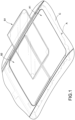
FIG. 2 is a perspective exploded view showing the window plate assembly according to the present disclosure; -
FIG. 3 is a partially enlarged view ofFIG. 2 ; and -
FIG. 4 is a cross-sectional view showing an operating status of the vehicle sunroof device according to the present disclosure. - The technical contents of this disclosure will become apparent with the detailed description of embodiments accompanied with the illustration of related drawings as follows. It is intended that the embodiments and drawings disclosed herein are to be considered illustrative rather than restrictive.
- Please refer from
FIG. 1 to FIG. 4 , the present disclosure provides a vehicle sunroof device and a window plate assembly thereof. The vehicle sunroof device includes a vehicle body and a window plate assembly. The vehicle body has a sunroof seat (that is, an opening or a window opening) A1 allowing the window plate assembly to be disposed. In some embodiments, the vehicle body includes a reinforced frame A and a sheet metal C. A top end and lateral sides of the reinforced frame A are covered by the sheet metal C to increase the structural strength via the reinforced frame A. The sunroof seat A1 is formed on the reinforced frame A and the sheet metal C allows the window plate assembly of the present disclosure to be disposed, here is not intended to be limiting. For example, the vehicle body may only include the sheet plate C. In some embodiments, the window plate assembly is a moveable sunroof B1 to make at least a part of the sunroof seat A1 be opened or closed, here is not intended to be limiting. For example, the window plate assembly may be a fixed window B2 to fix and close the whole or at least a part of the sunroof seat A1. In some embodiments, the following illustrations is provided for the movable sunroof B1. In some embodiments, the window plate assembly includes aglass panel 10, awindow frame 20 and aseal 30. - In some embodiments, the
glass panel 10 is formed in a rectangular shape. Four corners of theglass panel 10 respectively have a round corner to prevent a situations of stress concentration from occurring, and a glass breaking situation may be avoided, here is not intended to be limiting. The designer may adjust the appearance of theglass panel 10 according to actual needs. - The
window frame 20 is corresponding to the appearance of theglass panel 10 and surrounds an outer periphery of theglass panel 10. An installingslot 21 is defined at a top end of thewindow frame 20. Theglass panel 10 is disposed in the installingslot 21. Theglass panel 10 is fastened in the installingslot 21 of thewindow frame 20 with an adhering, a pressing or a buckling method, here is not intended to be limiting as long as theglass panel 10 is fastened in the installingslot 21. Abuckling groove 22 is defined at an outer periphery of thewindow frame 20, and ablock flange 23 is extended from the outer periphery of thewindow frame 20. Aplanar surface 24 is formed between the bucklinggroove 22 and theblock flange 23. Theblock flange 23 is located at the top end of thewindow frame 20 and extended in a direction away from theglass panel 10. The bucklinggroove 22 is located at a bottom end of thewindow frame 20. In some embodiments, thewindow frame 20 andblock flange 23 are formed through an injecting forming means utilizing polyurethane to be integrated as one piece (or integrally formed), here is not intended to be limiting. Thewindow frame 20 and theblock flange 23 can also be formed through an injection forming means utilizing other materials, for example a plastic material, to be integrated as one piece. - In some embodiments, the
seal 30 is made of a rubber material, here is not intended to be limiting. Theseal 30 is disposed on the outer periphery of thewindow frame 20, thus a sealing status is formed between theseal 30 and thewindow frame 20. Anabutting part 31 is formed at one side of theseal 30, and a bucklingpart 32 is extended from the abuttingpart 31. The bucklingpart 32 is buckled in the bucklinggroove 22 of thewindow frame 20 to make theabutting part 31 tightly abut against theplanar surface 24 and theblock flange 23 of thewindow frame 20, thus theseal 30 is fastened on thewindow frame 20, and a sealing status is formed between theseal 30 and thewindow frame 20. An included angle θ is defined between theblock flange 23 and theplanar surface 24. The included angle θ is smaller than or equal to 90°, thus theblock flange 23 tightly abuts against at least one portion of theabutting part 31, and theblock flange 23 partially covers a top end of theseal 30. As such, theseal 30 is easy to be detached relative to thewindow frame 20, and the sealing effect between theseal 30 and thewindow frame 20 may be ensured. In some embodiments, a guidinginclined surface 25 is respectively formed at a top opening and a bottom opening of the bucklinggroove 22, thus the bucklingpart 32 is inserted in the bucklinggroove 22 along the guidinginclined surface 25, here is not intended to be limiting. - Details are provided as follows. The buckling
part 32 includes amain body 321 and alatching hook 322. Areserved hook 221 is formed in the bucklinggroove 22. When themain body 321 is inserted in the bucklinggroove 22, the latchinghook 322 is correspondingly latched with the reversedhook 221. In some embodiments, there are two latchinghooks 322 and two reversed hooks 221. The latchinghook 322 is respectively located at a top end and a bottom end of themain body 321. The reversed 221 is respectively located at a top end and a bottom end of the bucklinggroove 22, here is not intended to be limiting. There is onelatching hook 322 and one reversedhook 221 as long as the buckling and fastening effect is achieved. In some embodiments, the bucklingpart 32 is a hollow structure as shown inFIG. 4 , thus the weight of theseal 30 is reduced, and the elastic deformation of the bucklingpart 32 is increased, here is not intended to be limiting. As such, if there is a manufacturing tolerance between the bucklingpart 32 and the bucklinggroove 22, the bucklingpart 32 is elastically deformed to be buckled in the bucklinggroove 22, thus the buckling match of the bucklingpart 32 and the bucklinggroove 22 is increased, and the requirement of the processing dimension is more flexible and the production cost is lowered. - A buckling direction of the buckling
part 32 and the bucklinggroove 22 is perpendicular to theplanar plane 24, thus theabutting part 31 tightly abuts towards theplanar plane 24 to form the sealing status when the bucklingpart 32 is buckled in the bucklinggroove 22 of thewindow frame 20. In some embodiments, a distance defined from a latching surface (not labelled in figures) of the latchinghook 322 to theabutting part 31 is slightly shorter than a distance defined from a latching surface (not labelled in figures) of the reversedhook 221 to theplanar surface 24, thus theabutting part 31 is ensured to tightly abut against theplanar surface 24 to form the sealing status after theseal 30 is latched on thewindow frame 20. - Please refer to
FIG. 4 , a cross section of theseal 30 is in a semi-circular shape, and theseal 30 is a hollow structure, here is not intended to be limiting. As such, when the window plate assembly closes (or, is engaged with) the sunroof seat A1 defined on the sheet metal C of the vehicle body, the abuttingpart 31 tightly abuts against theplanar surface 24 to form the sealing status, the arched side (in other words, the side of theseal 30 opposite to the abutting part 31) tightly abuts against an inner edge of the sunroof seat A1 of the sheet metal C of the vehicle body to form the sealing status. Because theseal 30 is the hollow structure, the weight of theseal 30 is reduced, and the elastic deformation is easily generated due to an internal hollow space in theseal 30, thus theseal 30 is tightly adhered with theplanar surface 24 and the inner edge of the sunroof seat A1 of the sheet metal C to achieve the desirable sealing effect.
Claims (10)
- A window plate assembly, comprising:a glass panel (10);a window frame (20), disposed at a periphery of the glass panel (10), wherein the window frame (20) comprises a buckling groove (22) defined on an outer periphery thereof and a block flange (23) extended from the outer periphery, and a planar surface (24) is disposed between the buckling groove (22) and the block flange (23); anda seal (30), comprising an abutting part (31) disposed on one side thereof and a buckling part (32) extended from the abutting part (31), wherein the buckling part (32) is buckled in the buckling groove (22) to make the abutting part (31) abut against the planar surface (24) and the block flange (23), and a buckling direction of the buckling part (32) and the buckling groove (22) is perpendicular to the planar surface (24).
- The window plate assembly according to claim 1, wherein the buckling part (32) comprises a main body (321) and a latching hook (322), a reserved hook (221) is disposed in the buckling groove (22), and when the main body (321) is inserted in the buckling groove (22), the latching hook (322) is correspondingly latched with the reversed hook (221).
- The window plate assembly according to claim 1, wherein a cross section of the seal (30) is in a semi-circular shape.
- The window plate assembly according to claim 1, wherein the window frame (20) comprises an installing slot (21), the glass panel (10) is disposed in the installing slot (21), and the block flange (23) is extended in a direction away from the glass panel (10).
- The window plate assembly according to claim 1, wherein an included angle is defined between the block flange (23) and the planar surface (24), and the included angle is smaller than 90°.
- The window plate assembly according to claim 1, wherein an included angle is defined between the block flange (23) and the planar surface (24), and the included angle is equal to 90°.
- The window plate assembly according to claim 1, wherein a guiding inclined surface (25) is disposed at an opening portion of the buckling groove (22).
- The window plate assembly according to claim 1, wherein the seal (30) is a hollow structure.
- The window plate assembly according to claim 1, wherein the buckling part (32) is a hollow structure.
- A vehicle sunroof device, comprising:a vehicle body, comprising a sunroof seat (A1); anda window plate assembly according to any claim from 1 to 9, disposed in the sunroof seat (A1), and when the window plate assembly is configured to close the sunroof seat (A1), the seal (30) abuts against an inner edge of the sunroof seat relative to one side of the abutting part (31).
Applications Claiming Priority (1)
| Application Number | Priority Date | Filing Date | Title |
|---|---|---|---|
| US202263415065P | 2022-10-11 | 2022-10-11 |
Publications (1)
| Publication Number | Publication Date |
|---|---|
| EP4357178A1 true EP4357178A1 (en) | 2024-04-24 |
Family
ID=86497409
Family Applications (6)
| Application Number | Title | Priority Date | Filing Date |
|---|---|---|---|
| EP23174481.4A Active EP4353507B1 (en) | 2022-10-11 | 2023-05-22 | Sunroof device |
| EP23175189.2A Withdrawn EP4353504A1 (en) | 2022-10-11 | 2023-05-24 | Anti-lift sunroof structure |
| EP23175265.0A Active EP4375101B1 (en) | 2022-10-11 | 2023-05-25 | Waterproof structure of vehicle sunroof |
| EP23177270.8A Pending EP4357177A1 (en) | 2022-10-11 | 2023-06-05 | Automotive sunroof apparatus and window panel assembly thereof |
| EP23179068.4A Withdrawn EP4357178A1 (en) | 2022-10-11 | 2023-06-13 | Vehicle sunroof device and window plate assembly thereof |
| EP23196420.6A Withdrawn EP4353506A1 (en) | 2022-10-11 | 2023-09-09 | Sunroof device |
Family Applications Before (4)
| Application Number | Title | Priority Date | Filing Date |
|---|---|---|---|
| EP23174481.4A Active EP4353507B1 (en) | 2022-10-11 | 2023-05-22 | Sunroof device |
| EP23175189.2A Withdrawn EP4353504A1 (en) | 2022-10-11 | 2023-05-24 | Anti-lift sunroof structure |
| EP23175265.0A Active EP4375101B1 (en) | 2022-10-11 | 2023-05-25 | Waterproof structure of vehicle sunroof |
| EP23177270.8A Pending EP4357177A1 (en) | 2022-10-11 | 2023-06-05 | Automotive sunroof apparatus and window panel assembly thereof |
Family Applications After (1)
| Application Number | Title | Priority Date | Filing Date |
|---|---|---|---|
| EP23196420.6A Withdrawn EP4353506A1 (en) | 2022-10-11 | 2023-09-09 | Sunroof device |
Country Status (4)
| Country | Link |
|---|---|
| US (6) | US12415409B2 (en) |
| EP (6) | EP4353507B1 (en) |
| JP (6) | JP2024056633A (en) |
| CN (6) | CN219467506U (en) |
Families Citing this family (2)
| Publication number | Priority date | Publication date | Assignee | Title |
|---|---|---|---|---|
| DE102021117708B3 (en) * | 2021-07-08 | 2022-08-25 | Webasto SE | Openable vehicle roof with roof cut-out and sealing arrangement |
| CN219467506U (en) | 2022-10-11 | 2023-08-04 | 福州明芳汽车部件工业有限公司 | sunroof device |
Citations (4)
| Publication number | Priority date | Publication date | Assignee | Title |
|---|---|---|---|---|
| US20100276969A1 (en) * | 2009-04-29 | 2010-11-04 | Inalfa Roof Systems Group B.V. | Method of producing a panel assembly |
| US20130193720A1 (en) * | 2010-12-06 | 2013-08-01 | Webasto SE | Sunroof apparatus |
| CN203623338U (en) * | 2013-12-02 | 2014-06-04 | 上海尚宏汽车天窗有限公司 | Semi-edge-cladding automobile skylight glass assembly |
| US10076952B2 (en) * | 2016-10-26 | 2018-09-18 | Yachiyo Industry Co., Ltd. | Sunroof unit |
Family Cites Families (40)
| Publication number | Priority date | Publication date | Assignee | Title |
|---|---|---|---|---|
| DE3323396A1 (en) * | 1983-06-29 | 1985-01-10 | Webasto-Werk W. Baier GmbH & Co, 8035 Gauting | SUNROOF WITH SLIDING SKY |
| FR2684050B1 (en) * | 1991-11-25 | 1995-06-16 | Standart Products Atlantic | SEALED CONNECTION DEVICE BETWEEN A MOBILE PANEL AND A FIXED FRAME OF A VEHICLE BODY. |
| DE4238889C2 (en) * | 1992-11-19 | 1995-04-13 | Webasto Schade Gmbh | Method for producing a lid of an openable vehicle roof |
| DE4308214C2 (en) * | 1993-03-15 | 1996-12-12 | Metzeler Automotive Profiles | Sealing arrangement for a lid on a vehicle roof |
| DE29606586U1 (en) * | 1996-04-11 | 1996-06-20 | Magna Zippex Autotechnik GmbH, 74374 Zaberfeld | Edge gap sealing profile |
| US5819472A (en) * | 1997-01-17 | 1998-10-13 | Green Tokai Co., Ltd. | Method and article of manufacture for reinforcing curved sections of hollow weatherstrip material |
| DE19830875C1 (en) * | 1998-07-10 | 1999-10-07 | Webasto Karosseriesysteme | Seal for motor vehicle sliding roof |
| DE29902662U1 (en) * | 1999-02-15 | 2000-07-06 | Meritor Automotive GmbH, 60314 Frankfurt | Adjustment device for a multi-spoiler roof for vehicles |
| US6598349B1 (en) * | 2000-03-02 | 2003-07-29 | Cooper Technology Services, Llc | Weatherstrip assembly with connecting member |
| JP2003211967A (en) * | 2002-01-21 | 2003-07-30 | Honda Motor Co Ltd | Glass panel for sunroof equipment |
| KR100774329B1 (en) * | 2006-08-10 | 2007-11-08 | 기아자동차주식회사 | Sunroof decoration cover assembly |
| DE102007015709B4 (en) * | 2007-01-25 | 2009-09-03 | Webasto Ag | vehicle roof |
| DE102007004818B3 (en) * | 2007-01-31 | 2008-05-29 | Webasto Ag | Vehicle roof consists of roof panel located in opening and having seal profiles around its panel edge |
| USD692370S1 (en) * | 2012-01-20 | 2013-10-29 | AISIN Technical Center of America, Inc. | Dual panel weather strip for a sunroof |
| JP2013169845A (en) * | 2012-02-20 | 2013-09-02 | Yachiyo Industry Co Ltd | Power supply structure to electric device in roof panel device |
| JP2014113926A (en) * | 2012-12-10 | 2014-06-26 | Nippon Sheet Glass Co Ltd | Window module |
| JP6018953B2 (en) * | 2013-03-06 | 2016-11-02 | ベバスト ジャパン株式会社 | Sunroof device |
| EP2829425A1 (en) * | 2013-07-23 | 2015-01-28 | Inalfa Roof Systems Group B.V. | Roof assembly for a vehicle |
| JP6225753B2 (en) * | 2014-02-28 | 2017-11-08 | アイシン精機株式会社 | Sunroof device |
| JP6561781B2 (en) * | 2015-11-06 | 2019-08-21 | アイシン精機株式会社 | Sunroof device |
| DE102016110586B3 (en) * | 2016-06-08 | 2017-08-24 | Roof Systems Germany Gmbh | Roof module for a vehicle and method of making a roof module |
| US9902245B2 (en) * | 2016-07-05 | 2018-02-27 | Fca Us Llc | Vehicle sunroof assembly |
| KR102429163B1 (en) * | 2016-11-29 | 2022-08-03 | 현대자동차주식회사 | Water Drain Structure of Sunroof in Vehicle |
| DE202017107486U1 (en) * | 2017-12-08 | 2019-03-12 | Inalfa Roof Systems Group B.V. | Open roof construction for a vehicle, and vehicle with such an open roof construction |
| US10293668B1 (en) * | 2017-12-12 | 2019-05-21 | Gm Global Technology Operations Llc. | Water management systems for vehicle sunroof assemblies |
| US10946731B2 (en) * | 2018-09-17 | 2021-03-16 | AISIN Technical Center of America, Inc. | Optimized middle rain channel |
| DE202018106758U1 (en) * | 2018-11-28 | 2020-03-02 | Inalfa Roof Systems Group B.V. | Panel and open roof construction provided with it |
| US20200377013A1 (en) * | 2019-05-27 | 2020-12-03 | Inalfa Roof Systems Group B.V. | Glass panel assembly for a roof of a vehicle |
| JP7018164B2 (en) * | 2019-08-27 | 2022-02-09 | 八千代工業株式会社 | Sunroof unit |
| DE102019126996A1 (en) * | 2019-10-08 | 2021-04-08 | Webasto SE | Sealing plug profile, arrangement for a vehicle roof and vehicle roof for a motor vehicle |
| EP3808582B1 (en) * | 2019-10-16 | 2023-06-07 | Inalfa Roof Systems Group B.V. | Roof system for a vehicle |
| EP3868586B1 (en) * | 2020-02-24 | 2023-10-25 | Inalfa Roof Systems Group B.V. | Open roof construction for a vehicle |
| CN113525051B (en) * | 2020-04-15 | 2024-05-31 | 长城汽车股份有限公司 | Sealing structure of automobile sunroof and automobile |
| US12005766B2 (en) * | 2020-10-19 | 2024-06-11 | AISIN Technical Center of America, Inc. | Sunroof drive apparatus and related sunroof assemblies for use with vehicles |
| CN112721597A (en) * | 2021-02-05 | 2021-04-30 | 宁波尚宏汽车天窗有限公司 | Novel sealed automobile panoramic sunroof assembly |
| DE102021111972A1 (en) * | 2021-05-07 | 2022-11-10 | Webasto SE | Openable vehicle roof with cover element, fixed roof element and sealing arrangement |
| CN115339302B (en) * | 2022-08-24 | 2025-11-04 | 芜湖莫森泰克汽车科技股份有限公司 | Sunroof glass edging and sealing strip connection structure |
| CN219467506U (en) | 2022-10-11 | 2023-08-04 | 福州明芳汽车部件工业有限公司 | sunroof device |
| US12576701B2 (en) * | 2023-09-05 | 2026-03-17 | Aisin Corporation | Sunroof assembly water management system |
| US20250296413A1 (en) * | 2024-03-25 | 2025-09-25 | AISIN Technical Center of America, Inc. | Sunshade assemblies with reduced height profiles |
-
2023
- 2023-02-07 CN CN202320187758.5U patent/CN219467506U/en active Active
- 2023-02-07 CN CN202310084600.XA patent/CN117863844A/en active Pending
- 2023-02-07 CN CN202310084322.8A patent/CN117863847A/en active Pending
- 2023-02-07 CN CN202320143744.3U patent/CN219467505U/en active Active
- 2023-02-07 CN CN202310075360.7A patent/CN117863843A/en active Pending
- 2023-02-07 CN CN202310075420.5A patent/CN117863848A/en active Pending
- 2023-05-18 US US18/199,351 patent/US12415409B2/en active Active
- 2023-05-22 EP EP23174481.4A patent/EP4353507B1/en active Active
- 2023-05-24 EP EP23175189.2A patent/EP4353504A1/en not_active Withdrawn
- 2023-05-25 US US18/202,280 patent/US20240116335A1/en active Pending
- 2023-05-25 EP EP23175265.0A patent/EP4375101B1/en active Active
- 2023-05-26 US US18/202,287 patent/US12420619B2/en active Active
- 2023-05-31 US US18/204,130 patent/US20240116343A1/en active Pending
- 2023-06-05 EP EP23177270.8A patent/EP4357177A1/en active Pending
- 2023-06-13 EP EP23179068.4A patent/EP4357178A1/en not_active Withdrawn
- 2023-06-14 US US18/210,057 patent/US20240116339A1/en active Pending
- 2023-09-05 US US18/242,490 patent/US20240116340A1/en active Pending
- 2023-09-09 EP EP23196420.6A patent/EP4353506A1/en not_active Withdrawn
- 2023-09-29 JP JP2023170145A patent/JP2024056633A/en active Pending
- 2023-09-29 JP JP2023170061A patent/JP7493660B2/en active Active
- 2023-09-29 JP JP2023170009A patent/JP2024056630A/en active Pending
- 2023-09-29 JP JP2023003601U patent/JP3244790U/en active Active
- 2023-09-29 JP JP2023003600U patent/JP3244789U/en active Active
- 2023-09-29 JP JP2023170098A patent/JP7493661B2/en active Active
Patent Citations (4)
| Publication number | Priority date | Publication date | Assignee | Title |
|---|---|---|---|---|
| US20100276969A1 (en) * | 2009-04-29 | 2010-11-04 | Inalfa Roof Systems Group B.V. | Method of producing a panel assembly |
| US20130193720A1 (en) * | 2010-12-06 | 2013-08-01 | Webasto SE | Sunroof apparatus |
| CN203623338U (en) * | 2013-12-02 | 2014-06-04 | 上海尚宏汽车天窗有限公司 | Semi-edge-cladding automobile skylight glass assembly |
| US10076952B2 (en) * | 2016-10-26 | 2018-09-18 | Yachiyo Industry Co., Ltd. | Sunroof unit |
Also Published As
| Publication number | Publication date |
|---|---|
| JP2024056632A (en) | 2024-04-23 |
| US12415409B2 (en) | 2025-09-16 |
| CN219467506U (en) | 2023-08-04 |
| CN117863843A (en) | 2024-04-12 |
| EP4375101B1 (en) | 2024-11-13 |
| US20240116340A1 (en) | 2024-04-11 |
| EP4353504A1 (en) | 2024-04-17 |
| EP4353507A1 (en) | 2024-04-17 |
| US20240116343A1 (en) | 2024-04-11 |
| JP7493660B2 (en) | 2024-05-31 |
| EP4375101A1 (en) | 2024-05-29 |
| EP4353507C0 (en) | 2025-12-31 |
| JP7493661B2 (en) | 2024-05-31 |
| CN117863848A (en) | 2024-04-12 |
| US20240116339A1 (en) | 2024-04-11 |
| EP4353506A1 (en) | 2024-04-17 |
| JP3244789U (en) | 2023-11-28 |
| JP3244790U (en) | 2023-11-28 |
| CN117863847A (en) | 2024-04-12 |
| US20240116335A1 (en) | 2024-04-11 |
| CN219467505U (en) | 2023-08-04 |
| JP2024056631A (en) | 2024-04-23 |
| JP2024056633A (en) | 2024-04-23 |
| EP4375101C0 (en) | 2024-11-13 |
| US20240116342A1 (en) | 2024-04-11 |
| JP2024056630A (en) | 2024-04-23 |
| EP4357177A1 (en) | 2024-04-24 |
| US12420619B2 (en) | 2025-09-23 |
| CN117863844A (en) | 2024-04-12 |
| US20240116338A1 (en) | 2024-04-11 |
| EP4353507B1 (en) | 2025-12-31 |
Similar Documents
| Publication | Publication Date | Title |
|---|---|---|
| EP4357178A1 (en) | Vehicle sunroof device and window plate assembly thereof | |
| JP5656928B2 (en) | Door weather strip | |
| KR100290747B1 (en) | Weather Strip | |
| US7648188B2 (en) | Glass run mounting structure | |
| CN107089123B (en) | Inner weather strip and sealing structure for vehicle door using same | |
| US11872872B2 (en) | Automotive door sealing member | |
| CN102470739A (en) | Sealing arrangement for vehicle glazing, method of manufacture thereof and use thereof | |
| US10583726B2 (en) | Glass run for automobile door | |
| US10035410B2 (en) | Parting seal and sealing structure of parting portion | |
| US11117454B2 (en) | Seal component for vehicle door window | |
| CN113635749B (en) | Edge covering strip, glass edge covering assembly and vehicle | |
| JP2000103242A (en) | Installing structure of glass run and glass run | |
| JPH01186424A (en) | Glass run structure for automobile door | |
| US5489135A (en) | Anti-squeak spacer and stop for automotive fixed glass | |
| US20230184333A1 (en) | Housing for motor vehicle-related uses | |
| US11865901B2 (en) | Glass run | |
| US10507714B2 (en) | Automotive sealing member | |
| CN214775304U (en) | A window glass with an insert | |
| CN113752961B (en) | A car window assembly with decorative parts | |
| US6070930A (en) | Structure for positioning window shield panel for vehicle and method of mounting window shield panel | |
| CN221213437U (en) | Door inner panel subassembly, door and vehicle | |
| US12257885B2 (en) | Vehicle door structure and manufacturing method for vehicle door structure | |
| CN118876677B (en) | Glass assembly, preparation method thereof and vehicle | |
| KR100941504B1 (en) | Automobile exterior molding and manufacturing method | |
| JP3376803B2 (en) | Car door sash molding mounting structure |
Legal Events
| Date | Code | Title | Description |
|---|---|---|---|
| PUAI | Public reference made under article 153(3) epc to a published international application that has entered the european phase |
Free format text: ORIGINAL CODE: 0009012 |
|
| STAA | Information on the status of an ep patent application or granted ep patent |
Free format text: STATUS: THE APPLICATION HAS BEEN PUBLISHED |
|
| AK | Designated contracting states |
Kind code of ref document: A1 Designated state(s): AL AT BE BG CH CY CZ DE DK EE ES FI FR GB GR HR HU IE IS IT LI LT LU LV MC ME MK MT NL NO PL PT RO RS SE SI SK SM TR |
|
| STAA | Information on the status of an ep patent application or granted ep patent |
Free format text: STATUS: REQUEST FOR EXAMINATION WAS MADE |
|
| 17P | Request for examination filed |
Effective date: 20241021 |
|
| RBV | Designated contracting states (corrected) |
Designated state(s): AL AT BE BG CH CY CZ DE DK EE ES FI FR GB GR HR HU IE IS IT LI LT LU LV MC ME MK MT NL NO PL PT RO RS SE SI SK SM TR |
|
| STAA | Information on the status of an ep patent application or granted ep patent |
Free format text: STATUS: EXAMINATION IS IN PROGRESS |
|
| 17Q | First examination report despatched |
Effective date: 20250911 |
|
| STAA | Information on the status of an ep patent application or granted ep patent |
Free format text: STATUS: THE APPLICATION HAS BEEN WITHDRAWN |
|
| 18W | Application withdrawn |
Effective date: 20251119 |