EP4357176A1 - Encapsulated fixed window module for a motor vehicle - Google Patents
Encapsulated fixed window module for a motor vehicle Download PDFInfo
- Publication number
- EP4357176A1 EP4357176A1 EP23202991.8A EP23202991A EP4357176A1 EP 4357176 A1 EP4357176 A1 EP 4357176A1 EP 23202991 A EP23202991 A EP 23202991A EP 4357176 A1 EP4357176 A1 EP 4357176A1
- Authority
- EP
- European Patent Office
- Prior art keywords
- fixed window
- over
- interior surface
- exterior
- interior
- Prior art date
- Legal status (The legal status is an assumption and is not a legal conclusion. Google has not performed a legal analysis and makes no representation as to the accuracy of the status listed.)
- Pending
Links
- 239000000463 material Substances 0.000 claims abstract description 106
- 230000002093 peripheral effect Effects 0.000 claims description 34
- 238000007789 sealing Methods 0.000 claims description 33
- 238000000465 moulding Methods 0.000 description 11
- 238000005538 encapsulation Methods 0.000 description 6
- 229920001169 thermoplastic Polymers 0.000 description 6
- 239000004416 thermosoftening plastic Substances 0.000 description 6
- 238000001125 extrusion Methods 0.000 description 5
- 239000011521 glass Substances 0.000 description 5
- 238000000034 method Methods 0.000 description 4
- 229920002943 EPDM rubber Polymers 0.000 description 3
- 239000004743 Polypropylene Substances 0.000 description 3
- 230000007547 defect Effects 0.000 description 3
- 229920001971 elastomer Polymers 0.000 description 2
- 239000000806 elastomer Substances 0.000 description 2
- 230000002708 enhancing effect Effects 0.000 description 2
- -1 polypropylene Polymers 0.000 description 2
- 229920001155 polypropylene Polymers 0.000 description 2
- 239000000243 solution Substances 0.000 description 2
- 241000251730 Chondrichthyes Species 0.000 description 1
- 238000004026 adhesive bonding Methods 0.000 description 1
- 230000015572 biosynthetic process Effects 0.000 description 1
- 230000001413 cellular effect Effects 0.000 description 1
- 230000007812 deficiency Effects 0.000 description 1
- 239000006261 foam material Substances 0.000 description 1
- 238000002347 injection Methods 0.000 description 1
- 239000007924 injection Substances 0.000 description 1
- 238000001746 injection moulding Methods 0.000 description 1
- 230000014759 maintenance of location Effects 0.000 description 1
- 239000002184 metal Substances 0.000 description 1
- 239000012778 molding material Substances 0.000 description 1
- 229920000642 polymer Polymers 0.000 description 1
- 238000010079 rubber tapping Methods 0.000 description 1
- 229920001935 styrene-ethylene-butadiene-styrene Polymers 0.000 description 1
- 239000012815 thermoplastic material Substances 0.000 description 1
- XLYOFNOQVPJJNP-UHFFFAOYSA-N water Substances O XLYOFNOQVPJJNP-UHFFFAOYSA-N 0.000 description 1
Images


Classifications
-
- B—PERFORMING OPERATIONS; TRANSPORTING
- B60—VEHICLES IN GENERAL
- B60J—WINDOWS, WINDSCREENS, NON-FIXED ROOFS, DOORS, OR SIMILAR DEVICES FOR VEHICLES; REMOVABLE EXTERNAL PROTECTIVE COVERINGS SPECIALLY ADAPTED FOR VEHICLES
- B60J10/00—Sealing arrangements
- B60J10/70—Sealing arrangements specially adapted for windows or windscreens
- B60J10/74—Sealing arrangements specially adapted for windows or windscreens for sliding window panes, e.g. sash guides
- B60J10/77—Sealing arrangements specially adapted for windows or windscreens for sliding window panes, e.g. sash guides for sashless windows, i.e. for frameless windows forming a seal directly with the vehicle body
- B60J10/777—Sealing arrangements specially adapted for windows or windscreens for sliding window panes, e.g. sash guides for sashless windows, i.e. for frameless windows forming a seal directly with the vehicle body the sealing arrangement being between the edges of adjacent panes
-
- B—PERFORMING OPERATIONS; TRANSPORTING
- B60—VEHICLES IN GENERAL
- B60J—WINDOWS, WINDSCREENS, NON-FIXED ROOFS, DOORS, OR SIMILAR DEVICES FOR VEHICLES; REMOVABLE EXTERNAL PROTECTIVE COVERINGS SPECIALLY ADAPTED FOR VEHICLES
- B60J10/00—Sealing arrangements
- B60J10/70—Sealing arrangements specially adapted for windows or windscreens
- B60J10/74—Sealing arrangements specially adapted for windows or windscreens for sliding window panes, e.g. sash guides
- B60J10/79—Sealing arrangements specially adapted for windows or windscreens for sliding window panes, e.g. sash guides for flush-glass windows, i.e. for windows flush with the vehicle body or the window frame
-
- B—PERFORMING OPERATIONS; TRANSPORTING
- B60—VEHICLES IN GENERAL
- B60J—WINDOWS, WINDSCREENS, NON-FIXED ROOFS, DOORS, OR SIMILAR DEVICES FOR VEHICLES; REMOVABLE EXTERNAL PROTECTIVE COVERINGS SPECIALLY ADAPTED FOR VEHICLES
- B60J1/00—Windows; Windscreens; Accessories therefor
- B60J1/08—Windows; Windscreens; Accessories therefor arranged at vehicle sides
- B60J1/10—Windows; Windscreens; Accessories therefor arranged at vehicle sides fixedly mounted
-
- B—PERFORMING OPERATIONS; TRANSPORTING
- B60—VEHICLES IN GENERAL
- B60J—WINDOWS, WINDSCREENS, NON-FIXED ROOFS, DOORS, OR SIMILAR DEVICES FOR VEHICLES; REMOVABLE EXTERNAL PROTECTIVE COVERINGS SPECIALLY ADAPTED FOR VEHICLES
- B60J10/00—Sealing arrangements
- B60J10/70—Sealing arrangements specially adapted for windows or windscreens
- B60J10/74—Sealing arrangements specially adapted for windows or windscreens for sliding window panes, e.g. sash guides
- B60J10/76—Sealing arrangements specially adapted for windows or windscreens for sliding window panes, e.g. sash guides for window sashes; for glass run channels
-
- B—PERFORMING OPERATIONS; TRANSPORTING
- B60—VEHICLES IN GENERAL
- B60J—WINDOWS, WINDSCREENS, NON-FIXED ROOFS, DOORS, OR SIMILAR DEVICES FOR VEHICLES; REMOVABLE EXTERNAL PROTECTIVE COVERINGS SPECIALLY ADAPTED FOR VEHICLES
- B60J10/00—Sealing arrangements
- B60J10/70—Sealing arrangements specially adapted for windows or windscreens
- B60J10/74—Sealing arrangements specially adapted for windows or windscreens for sliding window panes, e.g. sash guides
- B60J10/78—Sealing arrangements specially adapted for windows or windscreens for sliding window panes, e.g. sash guides adjacent to corner pieces, mirror supports or quarter windows
Landscapes
- Engineering & Computer Science (AREA)
- Mechanical Engineering (AREA)
- Seal Device For Vehicle (AREA)
- Window Of Vehicle (AREA)
Abstract
An encapsulated fixed window module for a motor vehicle, comprising:
a fixed window pane,
a first division post profile defining a longitudinal groove configured to receive a guiding mean carried by a movable window pane, and having an exterior wall facing a fixed pane interior surface, and
an over-molded material securing said first division post profile to said fixed window pane, said over-molded material comprising a first over-molded portion extending between said division post exterior wall and said fixed pane interior surface and a second over-molded portion extending between said lateral wall and said interior surface, said first over-molded portion having a first thickness which is constant along a major portion of said first over-molded portion,
wherein said second over-molded portion has a second thickness which is constant along a major portion of said second portion due to a co-extruded feature or "tooth" on the first division post profile.
Description
- The present invention relates generally to an encapsulated fixed window module for a motor vehicle and such a motor vehicle.
- In a number of motor vehicles, a door assembly is designed such that there is a first, e.g., forward, window opening that carries a movable window pane and a second, e.g., rearward, opening that is equipped with a fixed or stationary window pane. Of course, the forward window pane may be fixed and the rearward window pane may be moveable. Fixed windows of conventional design may be assembled from discrete elements that include the window panel, a post that serves as a track for an adjacent movable window and various configurations of moldings or trim pieces or division posts, most specifically an extruded header/B-pillar trim piece that may be mechanically attached to the window module assembly using an interlocking channel or the like.
- The division post in some prior art designs comprises an article in the nature of a pre-formed resilient band. In those designs, the window is inserted into a channel of the trim band which resiliently engages the window pane, but often less than securely. Conventional designs suffer from a number of deficiencies due to their assembly from discrete components such as water leakage, noise from the exterior (wind noise) or the interior, and problems generally with fit and finish. In addition, the assembly of these modules is often difficult, particularly where the individual components are manufactured by more than one supplier.
- A few of the problems of conventional designs are overcome through the use of over-molding processes by which a portion of the trim or post surrounding the window pane is fabricated by encapsulating the window periphery with a polymer using injection molding techniques. In essence, the window pane is placed in a mold cavity which is configured to produce a circumferential trim at the pane edges. A division post profile and a header profile are also placed in the mold cavity. In some case, an additional margin seal extrusion can be added to the mold cavity. The edges of the pane on which the injection molded trim will adhere are cleaned and primed to promote adhesion and to create a water-impervious seal in the formed article. The mold is then closed and the material is injected such that the window pane edges are encapsulated to form the desired trim geometry.
-
Figure 1 is a cross sectional view of adjacent window panes 1, 2 of a motor vehicle. The window pane 1 is fixed and the window pane 2 is movable. The fixed window pane 1 has an exterior surface 1a, aninterior surface 1b, and a peripheral edge 1c extending between said exterior andinterior surfaces 1a, 1b. A division post 3 extends along the peripheral edge 1c and is secured thereto by an over-molded material 4. - The division post 3 is U-shaped in cross section and has an
exterior wall 3a, aninterior wall 3b, and a lateral wall 3c connecting said exterior andinterior walls longitudinal groove 5 configured to receive a portion of the movable window pane 2. The lateral wall 3c of the division post 3 is in abutment against the peripheral edge 1c of the fixed window pane 1 and said over-molded material 4 comprises afirst portion 4a extending between the lateral wall 3c and the exterior surface 1a, and a second portion 4b extending between the lateral wall 3c and theinterior surface 1b. - This configuration creates a small offset O between the
interior surface 1b and theinterior wall 3b and requires limited amount of over-molded material on both sides of the fixed window pane 1. The risk of appearance issue due to sink marks is therefore low. - The exterior appearance of the window modules is very important for the customer, i.e., the user of the motor vehicle. A solution for enhancing the appearance of a window module is to provide the periphery of the window pane with finished panels which are located outside the motor vehicle and are visible by the user. Said finished panels are for instance esthetic metal components which are secured to the window module.
- It is also known to enhance the esthetic appearance of a window module by lying flush the outside of its stationary window pane with the outside of an adjacent movable window pane.
-
Figure 2 is a cross sectional view of adjacent and flush window panes 1, 2 of a motor vehicle. The division post 3 extends along the peripheral edge 1c and is secured to theinterior surface 1b by an over-molded material 4. - The division post 3 defines a
longitudinal groove 5 configured to receive a guiding mean 6 carried by the movable window pane 2. Theexterior wall 3a of the division post 3 faces theinterior surface 1b and is secured thereto by the over-molded material 4. - The over-molded material 4 comprises a
first portion 4a extending between theexterior wall 3a and theinterior surface 1b and a second portion 4b extending between the lateral wall 3c and theinterior surface 1b.Figure 2 shows that thefirst portion 4a has a thickness E1 which is constant (the thickness, E1 being measured in a direction D1 perpendicular to theinterior surface 1b and/or to theexterior wall 3a). On the contrary, the second portion 4b has a bigger thickness E2 which is not constant and which varies (the thickness, E2 is measured in a direction D2 perpendicular to the lateral wall 3c). The thickness E2 of the second portion 4b is higher in the proximity of theinterior surface 1b than on the opposite end in the proximity of theinterior wall 3b. - The over-molded material 4 comprises an outer face 4c which extends between the lateral wall 3c and the
interior surface 1b and which includes a major portion 4c1 which is inclined with respect to theinterior surface 1b. Due to feasibility reasons, it is not possible to get a major portion 4c1 perpendicular to theinterior surface 1b during the over-molding process. - In this flush configuration, a large offset O is created between the
interior surface 1b and theinterior wall 3b and a large amount of over-molded material 4 is needed to fill this offset O. The risk of appearance issue due to sink marks is therefore high. Indeed, after de-molding, the over-molded material 4 cools and hardens. The large amount of over-molded material promotes the formation of sink marks and surface defects on the outer face 4c. Since this outer face 4c may be visible to the user of the motor vehicle, these sink marks and surface defects are problematic. - The present invention provides at least an encapsulated fixed window module which can be used in a flush configuration and which avoids the above-mentioned appearance issue of the over-molded material.
- According to the invention there is provided an encapsulated fixed window module for a motor vehicle, comprising:
- a fixed window pane having an exterior surface, an interior surface, and a peripheral edge extending between said exterior and interior surfaces,
- at least one division post extending along at least a portion of said peripheral edge, said division post comprising a first longitudinal profile which is U-shaped in cross section and which has an exterior wall, an interior wall, and a lateral wall connecting said exterior and interior walls, said first profile defining a longitudinal groove configured to receive a guiding mean carried by a movable window pane, said exterior wall facing said interior surface, and
- an over-molded material securing said first profile to said fixed window pane, said over-molded material comprising a first portion extending between said exterior wall and said interior surface and a second portion extending between said lateral wall and said interior surface, said first and second portions being connected one to the other, said first portion having a first thickness which is constant along a major portion of said first portion, said second portion having an outer face which extends between the lateral wall and said interior surface and which includes a major portion which is inclined with respect to said interior surface,
- wherein said second portion has a second thickness which is constant along a major portion of said second portion.
- In the present specification, the words "inner", "inside", "interior", etc., make reference to the inside of a motor vehicle. The words "outer" "outside", "exterior", etc., make reference to the outside of the motor vehicle. Then, an outer element is located at the outer side of the vehicle. A first outer element, portion or surface may be visible by a user of the motor vehicle or may be hidden by a second outer element, portion or surface covering said first outer element.
- In the present specification, "aligned" and "substantially aligned" mean that two elements are strictly aligned or are aligned in a range 0 to 5mm, preferably 0 to 3mm and more preferably 0 to 1mm.
- The present invention provides a solution for enhancing the esthetic appearance of a fixed window module. This aim is achieved by keeping the thickness of the over-molded material as constant as possible. The second portion of the over-molded material is constant along a major portion of this second portion along a direction perpendicular to the interior surface of the fixed window pane. The thicknesses of the first and second portions of the over-molded material may be similar. Having a consistent thickness allows all the molded areas to cool at the same speed and prevent "sink-marks" and other appearance defects.
- The encapsulated fixed window module according to the invention may comprise one or more of the following features, taken alone from each other or in combination with each other:
- said lateral wall comprises a tooth which includes a first surface parallel to said interior surface, and a second surface which is inclined with respect to said interior surface, said first portion extending between said first surface and said interior surface and said second portion extending between said second surface and said interior surface;
- -- said first profile is extruded;
- -- said tooth is co-extruded with said first profile;
- said first surface is planar and said second surface is planar or curved;
- said second surface is concave or convex;
- said second surface is mainly parallel to said outer surface or provides a constant offset when this second surface is concave or convex;
- said first and second surfaces are V-shaped in cross section;
- said tooth has a tip having an angle comprises between 20 and 85°, and preferably between 50 and 70°;
- said over-molded material is V-shaped;
- -- said over-molded material includes a protruding rib extending on the interior surface;
- - said exterior wall comprises a longitudinal end opposite said lateral wall, said longitudinal end comprising a protruding leg which is perpendicular to the exterior wall and is in abutment against said peripheral edge;
- said protruding leg carries a first sealing lip which is configured to abut against a peripheral edge of said movable window pane;
- said longitudinal end and/or said exterior wall carries a protruding lip which abuts against said interior face and which is in contact with said over-molded material; said protruding lip is advantageous because it is used as a mold shut off between the fixed pane and the first profile;
- an empty space is defined between said fixed window pane on one hand, and said protruding leg and lip on the other hand;
- -- 0,8.E1 ≤ E2 ≤ 1,2.E1 ; and preferably 0,9.E1 ≤ E2 ≤ 1,1.E1; and more preferably E1 = E2; E1 and E2 being respectively said first and second thicknesses;
- said first profile comprises an embedded metallic rail which includes a leg extending outwardly and facing said peripheral edge;
- -- the thicknesses of the first and second portions are constant along a major portion of a length of the first profile;
- -- the thickness of the first portion is measured in a direction which is perpendicular to the interior surface of the fixed window pane; this direction may be perpendicular to said exterior wall or to a surface of said exterior wall;
- -- the thickness of the second portion is measured in a direction which is perpendicular to said lateral wall or to a surface of said lateral wall;
- -- the thickness of the first portion is substantially constant when the first profile is viewed in cross section;
- -- the thickness of the second portion is constant when the first profile is viewed in cross section;
- -- said over-molded material does not cover said peripheral edge along said first profile;
- -- said exterior wall of said first profile is applied onto said interior surface;
- -- said exterior wall is L-shaped in cross section and includes first and second parts that are perpendicular one another, said first part being spaced from said interior surface and extending between said lateral wall and said second part, said second part being applied directly onto said interior surface;
- -- said first part defines a space with said interior surface that is filled in with said over-molded material;
- -- said over-molded material extends at least between said exterior and lateral walls and said interior surface;
- -- said interior wall faces said guiding mean and an interior surface of said movable window pane;
- -- said interior wall carries a second sealing lip which is configured to be in sealing contact with said guiding mean;
- -- said interior wall carries a third sealing lip which is configured to be in sealing contact with said movable window pane;
- -- said exterior wall is coated with an antifriction layer inside said longitudinal groove;
- -- said lateral wall is coated with an antifriction layer inside said longitudinal groove;
- -- said interior wall is coated with an antifriction layer inside said longitudinal groove;
- -- said module further comprises a second longitudinal profile which is U-shaped in cross section and which has an exterior wall connecting therebetween two lateral walls, said second profile defining a longitudinal groove configured to receive a metallic flange of the motor vehicle;
- -- said exterior wall of said second profile is parallel to said interior surface and is secured thereto by an over-molded material, one of said lateral walls of said second profile being substantially aligned with a portion of said peripheral edge in a plane that is perpendicular to said fixed window pane, and the other of said lateral walls of said second profile extending perpendicularly and facing said interior surface;
- -- said exterior wall of said second profile is spaced from said interior surface;
- -- said module further comprises a third longitudinal profile which connects therebetween first and second longitudinal profiles;
- -- said module further comprises a third longitudinal profile which extends along at least an upper portion of said peripheral edge of said fixed window pane, and which is adjacent to said profile;
- -- said third longitudinal profile comprises first and second U-shaped portions, said first U-shaped portion being configured to receive a metallic flange of the motor vehicle and the second U-shaped portion being configured to receive by sliding said movable window pane;
- -- said first and second U-shaped portions define respectively two longitudinal grooves which are perpendicular one another;
- said over-molded material further comprises a third portion which is connected to the first portion and which is interposed between said leg and said peripheral edge;
- said over-molded material further comprises a third portion which is connected to the first portion, said third portion extending perpendicularly to the first portion and on said peripheral edge;
- said third portion includes an end which is coplanar with said exterior surface of said fixed window pane;
- -- the (co-extruded) material of the tooth is different from the (co-extruded) material of the first longitudinal profile;
- -- the (co-extruded) material of the protruding lip is different from the (co-extruded) material of the first longitudinal profile;
- -- the (co-extruded) material of the protruding leg is different from the (co-extruded) material of the first longitudinal profile;
- -- the material(s) of the tooth, and/or the protruding leg, and/or the protruding lip is/are softer or less hard than the material of the first longitudinal profile and in particular a covering material of this first longitudinal profile.
- The invention further proposes a motor vehicle, comprising at least one encapsulated fixed window module as defined above.
- The motor vehicle may comprise a door including a door frame, a movable window pane, and said encapsulated fixed window module, said movable window pane having an exterior surface, an interior surface, and a peripheral edge extending between said exterior and interior surfaces, wherein said exterior surfaces of said encapsulated fixed window module and of said movable window pane are substantially coplanar.
- The invention will be better understood and other details, features and advantages of the invention will appear more clearly on reading the following description given by way of non-limiting examples and with reference to the accompanying drawings in which:
-
Figure 1 is a cross sectional view of adjacent window panes including a fixed window pane carrying a division post, and a movable window pane guided into a groove of the division post; -
Figure 2 is a cross sectional view of adjacent and flush window panes including a fixed window pane carrying a division post, and a movable window pane carrying a guiding mean engaged into a groove of the division post; -
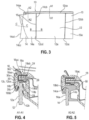
Figure 3 is a fragmentary side view of an encapsulated fixed window module; -
Figure 4 is a cross sectional view along line A1-A1 ofFigure 3 ; -
Figure 5 is a cross sectional view along line A2-A2 ofFigure 3 ; -
Figure 6 is a cross sectional view along line C-C ofFigure 3 ; -
Figure 7 is a cross sectional view along line B-B ofFigure 3 ; -
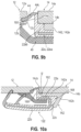
Figure 8 is a cross sectional view similar toFigures 1 and7 and showing a first embodiment of the encapsulated fixed window module according to the invention; -
Figure 9a is an enlarged view of a detail offigure 8 ; -
Figure 9b is an enlarged view of another detail offigure 8 ; and -
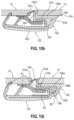
Figures 10a to 10i are views corresponding to the view offigure 8 and showing further embodiments of the invention. -
Figures 1 and 2 have been already described and illustrate the prior art. -
Figure 3 shows an example of an encapsulated fixedwindow module 10 for a motor vehicle. - A motor vehicle door comprises a door frame provided with an encapsulated fixed
window module 10 which can be adjacent to amovable window pane 12. In the example ofFigure 1 , a rear door of a vehicle is shown in which case thepane 12 is a forward pane and themodule 10 is a rearward module. Another configuration would be on a front door, with in that case themovable window pane 12 positioned rearwardly from themodule 10. - The
module 10 includes at least afixed window pane 14 molded on up to four extremities or along four edges. The or each molding forms anencapsulation 16. - Each
pane exterior surface interior surface peripheral edge Figures 4 and6 ). - Each
pane surfaces pane Figures 4 to 6 , theperipheral edge - In the example shown, each
pane peripheral edge Figure 3 ). - The door may further comprise an
appliqué 13, themovable window pane 12 being located between thestationary window pane 14 and theappliqué 13. Theexterior surface 12a of thepane 12 is advantageously flush with theexterior surface 14a of thepane 14a and theexterior surface 13a of theappliqué 13. -
Figure 4 is a cross sectional view at the top edge 12ca of the movable window pane.Figure 5 is a cross sectional view at the top edge 14ca of the fixed window pane.Figure 6 is a cross sectional view at the rear edge 14cd of the fixed window pane.Figure 7 is a cross sectional view at the front edge 14cb of the fixed window pane and at the rear edge 12cd of themovable window pane 12. - These figures show that the
encapsulation 16 extends along the edges 14ca, 14cb and 14cd of thepane 14. Glass edge 14ca and the inboard side of the glass next to 14cb are encapsulated. Encapsulation of glass edges 14cd and 14cc is optional. - Thus, the
encapsulation 16 extends along at least two edges of thepane 14 in the example shown but may not necessarily cover these edges as will be detailed below. Theencapsulation 16 may comprise segments or profiles or division posts each extending along a portion of the longitudinal edges of thepane 14. Each profile of the division post has a length and a width, its length being greater than its width and extending along said portion of the longitudinal edges of thepane 14. -
Figure 4 shows a longitudinal profile which is called "third"profile 18. Thisthird profile 18 extends along said edges 14ca and 12ca. The portion of theprofile 18 shown infigure 4 is the one extending along the edge 12ca and is not over-molded. - A substantially vertical profile (not shown) is molded to profile 18 to be part of
module 10, in order to guide the moveable glass edge 12cb. - The
third profile 18 shown infigure 4 has first and secondU-shaped portions - The first
U-shaped portion 18a defines alongitudinal groove 24 that is oriented inwardly and is configured to receive ametallic flange 26 of the motor vehicle. In the example shown, the metallic flange includes two substantially horizontal panels that are superimposed and inserted into thegroove 26. Thefirst portion 18a includes an exterior wall 18aa connecting two lateral walls 18ab, 18ac defining thegroove 26 therebetween. - The second
U-shaped portion 18b defines alongitudinal groove 28 that is oriented downwardly in a plane parallel to thepanes movable window pane 12. Thesecond portion 18b includes an interior wall 18ba and an exterior wall 18bb connected by a lateral wall which may be integrated in said lateral wall 18ac as shown in the figure. The walls of thesecond portion 18b define saidgroove 28. - Both
portions pane 12 and/or parts of the vehicle. - The
third profile 18 further may include an elongatedesthetic component 30 which extends along theprofile 18 and is secured onto bothportions component 30 includes an estheticexterior face 30a and aninterior face 30b. Thecomponent 30 includes a substantially flat portion including thefaces longitudinal hooks 30c extending inwardly from theinner face 30b. Thehooks 30c are used to mechanically secure thecomponent 30 onto theprofile 18. Thecomponent 30 is intended to cover at least portions of said exterior walls 18aa, 18bb which both comprise grooves intended to receive thehooks 30c by snap fitting. -
Figure 5 still shows thethird profile 18 and in particular its portion extending along the edge 14ca and is over-molded. - This portion of the
profile 18 differs from the portion offigure 2 in that it does not comprise the interior wall 18ba and in that it is secured to the fixedwindow pane 12 by anover-molded material 50. - This
over-molded material 50 extends onto the inner surface of the exterior wall 18bb, the downward surface of the lateral wall 18ac and also over the edge 14ca and portions of thesurfaces window pane 14. Thisover-molded material 50 may have lips or legs intended to abut against parts of the vehicle. -
Figure 6 shows a longitudinal profile which is called "second"profile 20. Thissecond profile 20 extends along said edge 14cd and is over-molded. - The
second profile 20 shown infigure 6 is U-shaped in cross section and defines alongitudinal groove 32 that is oriented inwardly and is configured to receive a metallic flange 34 of the motor vehicle. In the example shown, the metallic flange 34 includes two substantially vertical panels that are superimposed and inserted into thegroove 32. - The
second profile 20 includes anexterior wall 20a and twolateral walls exterior wall 20a. Theexterior wall 20a is usually parallel to theinterior surface 14b of the fixedwindow pane 14 and is secured thereto by anover-molded material 36. In the example shown, theexterior wall 20a faces theinterior surface 14b and spaced therefrom. This space S is filled in with saidover-molded material 36. - The
lateral wall 20b is substantially aligned with a portion (the rear edge 14cd in the example shown) of saidperipheral edge 14c in a plane P1 that is perpendicular to the fixedwindow pane 14. Thelateral wall 20c extends perpendicularly to and faces theinterior surface 14b. - In the example shown, the
over-molded material 36 further extends over thelateral wall 20c and the frond edge 14cd. Thelateral wall 20b is free of suchover-molded material 36. Saidover-molded material 36 is V-shaped (with an angle lower than 90°) in front of the rear edge 14cd and defines a firstplanar surface 36a aligned with theexterior surface 14a and a secondplanar surface 36b which extends between thefirst surface 36a and theprofile 20 and is inclined with respect to said plane P1. - The
second profile 20 includes sealing or retention lips intended to cooperate with parts of the vehicle. -
Figure 7 shows another longitudinal profile which is called "first"profile 22, also known as division post. Thisfirst profile 22 extends substantially vertically along said edges 12cd, 14cb and is over-molded. - The
first profile 22 shown infigure 7 is U-shaped in cross section and defines alongitudinal groove 38 that is oriented forwardly and is configured to receive a guiding mean 40 secured to themovable window pane 12. - The
first profile 22 includes anexterior wall 22a and aninterior wall 22b connected together by alateral wall 22c and defining the groove therebetween. Theexterior wall 22a is parallel to theinterior surface 14b of the fixedwindow pane 14 and is secured thereto by anover-molded material 42. In the example shown, theexterior wall 22a faces theinterior surface 14b and is L-shaped in cross section. Theexterior wall 22a includes first and second parts 22aa, 22ab that are perpendicular to one another, said first part 22aa being spaced from theinterior surface 14b and extending between saidlateral wall 22c and said second part 22ab. Said second part 22ab is applied directly onto said interior surface 14b. Said first part 22ab defines a space S with saidinterior surface 14b that is filled in with theover-molded material 42. - The
over-molded material 42 further extends over at least a portion of saidlateral wall 22c. Theover-molded material 42 does not cover the peripheral edge 14cb along saidfirst profile 22, i.e., the front edge 14cb, in the example shown. - The
exterior wall 22a has a longitudinal edge 22a1 which is opposite to thelateral wall 22c that is substantially aligned with said front edge 14cb in a plane P2 that is perpendicular to the fixedwindow pane 14. - This longitudinal edge 22a1 carries a
first sealing lip 44 which is configured to abut against both edges 14cb and 12cd. The sealinglip 44 is the sole member extending between said edges 14cb and 12cd. The sealinglip 44 is curved (concave or convex) and defines a groove oriented inwardly. Thelip 44 includes a longitudinal connectingedge 44a which extends in the plane P2 and is secured to the longitudinal edge 22a1, and further includes an oppositelongitudinal sealing edge 44b abutting against the rear edge 12cd of thepane 12. The longitudinal portion of the sealinglip 44 extending between bothedges exterior surface 44c which is substantially aligned with saidexterior surfaces - As far as the
interior wall 22b of thefirst profile 22 is concerned, it crosses said plane P2 and is configured to face said guidingmean 40, and preferably also to face theinterior surface 12b of themovable window pane 12 as shown in the figure. - The
interior wall 22b carries asecond sealing lip 46 which is configured to be in sealing contact with the guidingmean 40. In another example, only the first and the third sealing lips may be provided (no sealing is then provided on the guiding mean 40). - The guiding mean 40 may be formed of a single longitudinal part that is secured, for instance by gluing or over-molding, onto the
interior surface 12b of thepane 12 and includes a guidingleg 40a crossing the plane P2 and received into thegroove 38 for sliding motion. As shown in the drawings, the surfaces of thegroove 38 may be coated with an antifriction layer suitable to cooperate by sliding with the guidingmean 40 and in particular itsleg 40a. Therefore, as shown in the drawings, thewalls groove 38. - As shown in
figures 4 to 7 , eachprofile profiles window pane 14 by over-molding by means of theover-molded material -
Figure 8 is a view similar to the view ofFigures 2 and7 and shows a first embodiment according to the invention. - The invention relates to an encapsulated fixed window module which is similar to the encapsulated window module described above in relation with
Figures 3 to 6 . The above description made in reference toFigure 3 to 6 applies therefore to the claimed invention and the description ofFigure 7 of the former embodiment may be replaced by the following description ofFigure 8 which illustrates the first embodiment of the invention. - The reference numerals used in relation to
Figures 3 to 7 are used for designating the same elements inFigure 8 . - The
window panes - The (first)
profile 122 or division post ofFigure 8 extends along the edges 12cd, 14cb and is over-molded. - The
profile 122 shown infigure 7 is U-shaped in cross section and defines alongitudinal groove 38 that is oriented forwardly and is configured to receive the guiding mean 40 secured to themovable window pane 12. - The
profile 122 includes anexterior wall 22a and aninterior wall 22b connected together by alateral wall 22c and defining thegroove 38 therebetween. Theexterior wall 22a is parallel to theinterior surface 14b of the fixedwindow pane 14 and is secured thereto by anover-molded material 142. - As shown in the drawings, the surfaces of the
groove 38 may be coated with an antifriction layer F1 suitable to cooperate by sliding with the guidingmean 40 and in particular itsleg 40a. Therefore, as shown in the drawings, thewalls groove 38. - The
exterior wall 22a has a surface 22a1 that faces theinterior surface 14b and is L-shaped in cross section. Theexterior wall 22a includes first and second parts 22aa, 22ab that are perpendicular one another, said first part 22aa being spaced from theinterior surface 14b and extending between saidlateral wall 22c and said second part 22ab. Said second part 22ab is applied directly onto saidinterior surface 14b in the vicinity of theedge 14c, 14cb. - Said second part 22ab carries a
protruding leg 160 which extends externally in a direction substantially perpendicular to theexterior wall 22a. Theprotruding leg 160 is interposed in the gap between both peripheral edges 12cb, 14cb, and is in abutment against the peripheral edge 14cb. Theprotruding leg 160 carries afirst sealing lip 44 which is configured to abut against the edge 12cb. Thefirst sealing lip 44 has anexterior surface 44c which is substantially aligned with theexterior surfaces - The
protruding leg 160 is made of the same material as the main material (or polymeric covering) of theprofile 122. Thefirst sealing lip 44 is preferably made of a softer material. - The
exterior wall 22a, and in particular its first part 22aa, defines a space S with theinterior surface 14b that is filled in with theover-molded material 142 and in particular with afirst portion 142a of thisover-molded material 142. - The
over-molded material 142 further extends over at least a portion of saidlateral wall 22c and comprises asecond portion 142b extending between thelateral wall 22c and theinterior surface 14b. Theover-molded material 142 does not cover the peripheral edge 14cb in the example shown. - As far as the
interior wall 22b of thefirst profile 22 is concerned, it is longer than theexterior wall 22a and is configured to face said guidingmean 40, and preferably also to face theinterior surface 12b of themovable window pane 12 as shown in the figure. - The
interior wall 22b carries asecond sealing lip 46 which is configured to be in sealing contact with the guidingmean 40, and a third sealing lip 48 which is configured to be in sealing contact with theinterior surface 12b of themovable window pane 12. - Sealing
lips - In another example, only the first and the third sealing lips may be provided (no sealing is then provided on the guiding mean 40).
- The
profile 122 may comprise at least one U-shaped metallic rail embedded or encapsulated into a polymeric covering. This rail may include a first branch extending into theexterior wall 22b, a second branch extending into theinterior wall 22a, and a connecting branch extending into thelateral wall 22c.
Theprofile 122 and its polymeric covering may be made by co-extrusion. The sealing lips may be made of an elastically deformable material, such as for example EPDM or thermoplastic. These lips may be realized by over-molding or co-extrusion. Of course, theprofile 122 might not comprise metallic rail and might therefore comprise only a polymeric material. The polymeric or covering material of theprofile 122 may be a thermoplastic or an elastomer thermoplastic, such as for instance polypropylene. The over-molded material is for instance made of thermoplastic, elastomer thermoplastic, EPDM, SEBS, etc. - As shown in
Figure 8 , thefirst portion 142a of theover-molded material 142 has a first thickness E1 which is constant along a major portion of this first portion. The thickness E1 of this first portion 142A is measured in a direction which is perpendicular to the interior surface 14B of the fixedwindow pane 14 and which is also perpendicular to theexterior wall 22a. - The
second portion 142b of theover-molded material 142 has a second thickness E2 which is constant along a major portion of the second portion. The thickness E2 of thissecond portion 142b is measured in a direction which is perpendicular to thelateral wall 22c. - This
second portion 142b has an outer face 142b1 which extends between thelateral wall 22c and theinterior surface 14b and which includes a major portion which is inclined with respect to theinterior surface 14b. - In the shown example, the
over-molded material 142 is V-shaped and includes bothportions tip 142c. Theover-molded material 142 includes aprotruding rib 166 on itstip 142c, this protrudingrib 166 extending on theinterior surface 14b (Figure 9a ). - In the example shown, the shape of the over-molded material is provided by the shape of the
profile 122 which includes atooth 168 or a fin (such as a shark fin) on itslateral wall 22c. - The
tooth 168 includes afirst surface 168a parallel to theinterior surface 14b and aligned with the surface 22a1 of theexterior wall 22a, and asecond surface 168b which is inclined with respect to the interior surface 14b.The function oftooth 168 is to create a constant offset between thesecond surface 168b and the outer face 142b1. The shape and location of thesurface 168b will thus evolve according to the shape and location of the outer face 142b1. The thickness E2 of thesecond portion 142b may be measured in a direction which is perpendicular to thissecond surface 168b. - The
tooth 168 is preferably fully embedded into the over-molded material so that thefirst portion 142a extends between thefirst surface 168a and theinterior surface 14b and thesecond portion 142b extends between thesecond surface 168b and theinterior surface 14b. Thefirst surface 168a is planar and thesecond surface 168b is also planar in the example shown. Thissecond surface 168b is preferably parallel to the outer face 142b1 to ensure that E2 is constant. The first andsecond surfaces second surfaces tooth 168 defines an angle α comprised between 20 and 85°, and preferably between 50 and 70°. -
Figures 10a to 10e show further embodiments of the invention. - The embodiment of
figure 10a differs from the embodiment offigure 8 in that the second part 22ab of theexterior wall 22a is replaced by a protrudinglip 162 which extends externally and which is in abutment against theinterior surface 14b of thewindow pane 14. - The protruding
lip 162 and theprotruding leg 160 may be made of the same material as the main material of theprofile 122. Thefirst sealing lip 44 is made of a softer material. - The
over-molded material 142 does not cover the peripheral edge 14cb. This is due to the presence of the protrudinglip 162 which abuts against thepane 14 and avoidover-molded material 142 passing through thelip 162 and up to the edge 14cb. - As shown in the drawings, the protruding
lip 162 andleg 160 may define together and with thepane 14 a space S' that is empty, i.e., that is not filled withover-molded material 142. - The embodiment of
figure 10b differs from the embodiment offigure 8 in that thetooth 168 defines a larger angle α of about 70-85°. The V-shape of theover-molded material 142 has a similar angle. - The embodiment of
figure 10c differs from the embodiment offigure 8 in that thetooth 168 defines a small angle α of about 20-40°. The V-shape of theover-molded material 142 has a similar angle. - The embodiment of
figure 10d differs from the embodiment offigure 8 in that thesecond surface 168b of thetooth 168 is curved and in particular is concave. Thesecond portion 142b of theover-molded material 142 conforms to the shape of thissecond surface 168b and has a curved shape. Similarly, the outer face 142b1 of theover-molded material 142 is curved and concave to get a thickness E2 as constant as possible. - The embodiment of
figure 10e differs from the embodiment offigure 8 in that thesecond surface 168b of thetooth 168 is curved an in particular convex. Thesecond portion 142b of theover-molded material 142 conforms to the shape of thissecond surface 168b and has a curved shape. Similarly, the outer face 142b1 of theover-molded material 142 is curved and convex to get a thickness E2 as constant as possible. - The embodiment of
figure 10f differs from the embodiment offigure 8 in that the metallic rail embedded or encapsulated into the polymeric covering includes aleg 170 at its edge opposite the connecting branch. Thisleg 170 extends outwardly and is interposed between the edges 12cd and 14cb. - The embodiment of
figure 10g differs from the embodiment offigure 8 in thatover-molded material 142 comprises athird portion 142c, thefirst portion 142a extending between the third andsecond portions - The
third portion 142c extends on the peripheral edge 14cb of the fixedpane 14. Thethird portion 142c is perpendicular to thefirst portion 142a and extends outwardly from the end of thefirst portion 142a which is opposite to thesecond portion 142b. Thethird portion 142c covers entirely the peripheral edge 14cb in the example shown. - Therefore, the
profile 122 is not directly in contact with thepane 14. Itsexterior wall 22b is remote from theinterior surface 14b and is separated therefrom by theover-molded material 142. - The
first sealing lip 44 of theprofile 122 is configured to abut against edge 12cd. Thethird portion 142c and the sealinglip 44 are both located between the edges 14cb and 12cd. - As shown, the
third portion 142c may include an end which is coplanar with said exterior surfaces of saidpanes - The embodiment of
figure 10g further differs in that the antifriction layer on the exterior surface of theinterior wall 22a of theprofile 122 is replaced by a co-extruded thermoplastic material and/or a cellular or foam material F2. This material is used to prevent rattle noise/tapping noise during door slam. The material F2 has for instance a shore A hardness of about 25-60 and/or a coefficient of friction less than about 0,6. All the embodiments described above may have such material in thegroove 38 instead of one of the antifriction layers F1. - In another embodiment shown in
figure 10h , thethird portion 142c offigure 10g may be combined with theleg 160 of any of the preceding embodiments (figure 8 to figure 10g ) and may therefore be interposed between the peripheral edge 14cb of thepane 14 and thisleg 160. - Generally speaking, the
third portion 142c is advantageous because it allows simplifying the mold that is used to perform the encapsulation. Moreover, it enhances the sealing during molding at the connecting area between the edges 14cb, 14ca (cf.figure 3 ). - In another embodiment shown in
figure 10i , thetooth 168 is made of a material which is different from the main (co-extruded or covering) material of theprofile 122. For instance, the main material of theprofile 122 is harder than the material of thetooth 168. The main material is for instance a PP. The material of thetooth 168 may have a Shore A hardness of between 70-95, and for instance of about 85. The material of thetooth 168 is for instance a TPE. - The
protruding leg 160 and the protrudinglip 162 may also be made of a material which is different from the main material of theprofile 122. The materials of theleg 160, of thelip 162 and of thetooth 168 may be the same. - Even if the
tooth 168 and/or theprotruding leg 160 and/or the protrudinglip 162 may be made of different material, they are preferably made by co-extrusion with theprofile 122. Use of a softer material for theprotruding leg 160 for instance enhances the molding operation. - The
second portion 142b extends on thetooth 168 and has an end linked to theprofile 122. Thisportion 142b has a constant thickness E2 up to this end. - In the embodiment of
figure 10i , both branches of the metallic rail of theprofile 122 are straight while in the embodiments offigures 10a-10h the exterior branch of the metallic rail is slightly inclined and has an end opposite its lateral branch which protrudes inwardly.
In all the embodiments, the esthetic appearance of the window module may be enhanced by lying flush theoutside surfaces movable window panes exterior surfaces panes surfaces exterior surface 44c (cf.figures 8 to 10f ), and/or with the end of the leg 160 (figures 8 to 10f ), and/or with the end of thethird portion 142c of the over-molding material 142 (figures 10g and10h ).
Claims (15)
- An encapsulated fixed window module (10) for a motor vehicle, comprising:a fixed window pane (14) having an exterior surface (14a), an interior surface (14b), and a peripheral edge (14c) extending between said exterior and interior surfaces (14a, 14b),at least one division post extending along at least a portion of said peripheral edge (14c), said division post comprising a first longitudinal profile (122) which is U-shaped in cross section and which has an exterior wall (22a), an interior wall (22b), and a lateral wall (22c) connecting said exterior and interior walls (22a, 22b), said first profile (22) defining a longitudinal groove (38) configured to receive a guiding mean (40) carried by a movable window pane (12), said exterior wall (22a) facing said interior surface (14b), andan over-molded material (142) securing said first profile (122) to said fixed window pane (14), said over-molded material (142) comprising a first portion (142a) extending between said exterior wall (22a) and said interior surface (14b) and a second portion (142b) extending between said lateral wall (22c) and said interior surface (14a), said first and second portions (142a, 142b) being connected one to the other, said first portion (142a) having a first thickness (E1) which is constant along a major portion of said first portion (142a), said second portion (142b) having an outer face (142b1) which extends between the lateral wall (22c) and said interior surface (14b) and which includes a major portion which is inclined with respect to said interior surface (14b),wherein said second portion (142b) has a second thickness (E2) which is constant along a major portion of said second portion (142b).
- The encapsulated fixed window module (10) as claimed in claim 1, wherein said lateral wall (22c) comprises a tooth (168) which includes a first surface (168a) parallel to said interior surface (14b) , and a second surface (168b) which is inclined with respect to said interior surface (14b), said first portion (142a) extending between said first surface (168a) and said interior surface (14b) and said second portion (142b) extending between said second surface (168b) and said interior surface (14b).
- The encapsulated fixed window module (10) as claimed in claim 2, wherein said first surface (168a) is planar and said second surface (168b) is planar, concave or convex.
- The encapsulated fixed window module (10) as claimed in claim 2 or 3, wherein said second surface (168b) is mainly parallel to said outer face (142b1) or provides a constant offset when this second surface (168b) is concave or convex.
- The encapsulated fixed window module (10) as claimed in any one of claims 2 to 4, wherein said first and second surfaces (168a, 168b) are V-shaped in cross section.
- The encapsulated fixed window module (10) as claimed in any one of claims 2 to 5, wherein said tooth (168) has a tip having an angle comprises between 20 and 85°, and preferably between 50 and 70°.
- The encapsulated fixed window module (10) as claimed in any one of claims 1 to 6, wherein said over-molded material (142) is V-shaped.
- The encapsulated fixed window module (10) as claimed in any one of claims 1 to 7, wherein 0,8.E1 ≤ E2 ≤ 1,2.E1, in which E1 and E2 are respectively said first and second thicknesses.
- The encapsulated fixed window module (10) as claimed in any one of claims 1 to 8, wherein said exterior wall (22a) comprises a longitudinal end opposite said lateral wall (22c), said longitudinal end comprising a protruding leg (160) which is perpendicular to the exterior wall (22a) and is in abutment against said peripheral edge (14c).
- The encapsulated fixed window module (10) as claimed in claim 9, wherein said protruding leg (160) carries a first sealing lip (44) which is configured to abut against a peripheral edge (12c) of said movable window pane (12).
- The encapsulated fixed window module (10) as claimed in claim 9 or 10, wherein said longitudinal end and/or said exterior wall (22b) carries a protruding lip (162) which abuts against said interior face (14b) and which is in contact with said over-molded material (142).
- The encapsulated fixed window module (10) as claimed in any one of claims 9 to 11, wherein an empty space (S') is defined between said fixed window pane (14) on one hand, and said protruding leg (160) and/or lip (162) on the other hand.
- The encapsulated fixed window module (10) as claimed in any one of preceding claims, wherein said over-molded material (142) further comprises a third portion (142c) which is connected to the first portion (142a), said third portion (142c) being interposed between said leg (160) and said peripheral edge (14c) or extending perpendicularly to the first portion (142a) and on said peripheral edge (14c).
- A motor vehicle, comprising at least one encapsulated fixed window module (10) as claimed in any one of preceding claims.
- The motor vehicle as claimed in claim 14, which comprises a door including a door frame, a movable window pane (12), and said encapsulated fixed window module (10), said movable window pane (12) having an exterior surface (12a), an interior surface (12b), and a peripheral edge (12c) extending between said exterior and interior surfaces (12a, 12b), wherein said exterior surfaces (12a, 14a) of said encapsulated fixed window module (10) and of said movable window pane (12) are substantially coplanar.
Applications Claiming Priority (1)
| Application Number | Priority Date | Filing Date | Title |
|---|---|---|---|
| US17/968,726 US20240123803A1 (en) | 2022-10-18 | 2022-10-18 | Encapsulated fixed window module for a motor vehicle |
Publications (1)
| Publication Number | Publication Date |
|---|---|
| EP4357176A1 true EP4357176A1 (en) | 2024-04-24 |
Family
ID=88373812
Family Applications (1)
| Application Number | Title | Priority Date | Filing Date |
|---|---|---|---|
| EP23202991.8A Pending EP4357176A1 (en) | 2022-10-18 | 2023-10-11 | Encapsulated fixed window module for a motor vehicle |
Country Status (4)
| Country | Link |
|---|---|
| US (1) | US20240123803A1 (en) |
| EP (1) | EP4357176A1 (en) |
| CN (1) | CN117901624A (en) |
| CA (1) | CA3210014A1 (en) |
Citations (2)
| Publication number | Priority date | Publication date | Assignee | Title |
|---|---|---|---|---|
| EP0195578B1 (en) * | 1985-03-13 | 1990-08-08 | Toyota Jidosha Kabushiki Kaisha | A vehicle door structure |
| EP3623191A1 (en) * | 2018-09-14 | 2020-03-18 | Hutchinson Sealing Systems | Encapsulated fixed window module for a motor vehicle |
-
2022
- 2022-10-18 US US17/968,726 patent/US20240123803A1/en active Pending
-
2023
- 2023-08-23 CA CA3210014A patent/CA3210014A1/en active Pending
- 2023-10-11 EP EP23202991.8A patent/EP4357176A1/en active Pending
- 2023-10-18 CN CN202311351367.3A patent/CN117901624A/en active Pending
Patent Citations (2)
| Publication number | Priority date | Publication date | Assignee | Title |
|---|---|---|---|---|
| EP0195578B1 (en) * | 1985-03-13 | 1990-08-08 | Toyota Jidosha Kabushiki Kaisha | A vehicle door structure |
| EP3623191A1 (en) * | 2018-09-14 | 2020-03-18 | Hutchinson Sealing Systems | Encapsulated fixed window module for a motor vehicle |
Also Published As
| Publication number | Publication date |
|---|---|
| US20240123803A1 (en) | 2024-04-18 |
| CN117901624A (en) | 2024-04-19 |
| CA3210014A1 (en) | 2024-04-18 |
Similar Documents
| Publication | Publication Date | Title |
|---|---|---|
| EP3623191A1 (en) | Encapsulated fixed window module for a motor vehicle | |
| US8166708B2 (en) | Integrated glass run and upper reveal with film | |
| KR101298509B1 (en) | Invisible division bar modular assembly | |
| US8001727B2 (en) | Sealing molding with insert for forming closeout surface | |
| US5317835A (en) | Window enclosure for an automotive upper door frame | |
| US8782954B2 (en) | Glass run | |
| KR101163472B1 (en) | Mounting structure of opening weather strip for car | |
| EP1864842B1 (en) | Glass run | |
| EP1751389B1 (en) | One-piece plastic retainer with integrated water management feature | |
| US10457121B2 (en) | Encapsulated fixed window module for a motor vehicle | |
| US20100095599A1 (en) | Sealing system for vehicle door leaf, method for making same and vehicle including same | |
| US20100102597A1 (en) | Glass Run With Integrated Upper Reveal | |
| US20020096800A1 (en) | Encapsulated fixed window module with continuous seal trim strip for a motor vehicle | |
| US5913762A (en) | Weatherstrip for motor vehicle side windows | |
| US20060150522A1 (en) | Window sealing and guiding arrangements | |
| EP4357176A1 (en) | Encapsulated fixed window module for a motor vehicle | |
| CN220129918U (en) | Encapsulated fixed window module for a motor vehicle, glass run and motor vehicle | |
| KR20240054202A (en) | Encapsulated fixed window module for a motor vehicle | |
| JP2024059592A (en) | Sealed fixed window module for automobiles | |
| KR100776653B1 (en) | Door frame sealing means of automobile | |
| JP2008132958A (en) | Weatherstrip for automobile | |
| JP3596628B2 (en) | Automotive seal structure | |
| JP2008030633A (en) | Outer weather strip | |
| JP2006213242A (en) | Glass run molded part | |
| JP2007008262A (en) | Glass run for automobile |
Legal Events
| Date | Code | Title | Description |
|---|---|---|---|
| PUAI | Public reference made under article 153(3) epc to a published international application that has entered the european phase |
Free format text: ORIGINAL CODE: 0009012 |
|
| STAA | Information on the status of an ep patent application or granted ep patent |
Free format text: STATUS: THE APPLICATION HAS BEEN PUBLISHED |
|
| AK | Designated contracting states |
Kind code of ref document: A1 Designated state(s): AL AT BE BG CH CY CZ DE DK EE ES FI FR GB GR HR HU IE IS IT LI LT LU LV MC ME MK MT NL NO PL PT RO RS SE SI SK SM TR |