EP4357153B1 - Innere verbindung einer fahrradhinterradnabe - Google Patents
Innere verbindung einer fahrradhinterradnabe Download PDFInfo
- Publication number
- EP4357153B1 EP4357153B1 EP22383008.4A EP22383008A EP4357153B1 EP 4357153 B1 EP4357153 B1 EP 4357153B1 EP 22383008 A EP22383008 A EP 22383008A EP 4357153 B1 EP4357153 B1 EP 4357153B1
- Authority
- EP
- European Patent Office
- Prior art keywords
- hub
- freehub
- bicycle wheel
- wheel hub
- rear bicycle
- Prior art date
- Legal status (The legal status is an assumption and is not a legal conclusion. Google has not performed a legal analysis and makes no representation as to the accuracy of the status listed.)
- Active
Links
Images


Classifications
-
- B—PERFORMING OPERATIONS; TRANSPORTING
- B60—VEHICLES IN GENERAL
- B60B—VEHICLE WHEELS; CASTORS; AXLES FOR WHEELS OR CASTORS; INCREASING WHEEL ADHESION
- B60B27/00—Hubs
- B60B27/0094—Hubs one or more of the bearing races are formed by the hub
-
- B—PERFORMING OPERATIONS; TRANSPORTING
- B60—VEHICLES IN GENERAL
- B60B—VEHICLE WHEELS; CASTORS; AXLES FOR WHEELS OR CASTORS; INCREASING WHEEL ADHESION
- B60B27/00—Hubs
- B60B27/02—Hubs adapted to be rotatably arranged on axle
- B60B27/023—Hubs adapted to be rotatably arranged on axle specially adapted for bicycles
-
- B—PERFORMING OPERATIONS; TRANSPORTING
- B60—VEHICLES IN GENERAL
- B60B—VEHICLE WHEELS; CASTORS; AXLES FOR WHEELS OR CASTORS; INCREASING WHEEL ADHESION
- B60B27/00—Hubs
- B60B27/02—Hubs adapted to be rotatably arranged on axle
- B60B27/04—Hubs adapted to be rotatably arranged on axle housing driving means, e.g. sprockets
- B60B27/047—Hubs adapted to be rotatably arranged on axle housing driving means, e.g. sprockets comprising a freewheel mechanisms
-
- B—PERFORMING OPERATIONS; TRANSPORTING
- B60—VEHICLES IN GENERAL
- B60B—VEHICLE WHEELS; CASTORS; AXLES FOR WHEELS OR CASTORS; INCREASING WHEEL ADHESION
- B60B2310/00—Manufacturing methods
- B60B2310/30—Manufacturing methods joining
- B60B2310/307—Manufacturing methods joining by removably mountable securing elements, e.g. circlips
-
- B—PERFORMING OPERATIONS; TRANSPORTING
- B60—VEHICLES IN GENERAL
- B60B—VEHICLE WHEELS; CASTORS; AXLES FOR WHEELS OR CASTORS; INCREASING WHEEL ADHESION
- B60B27/00—Hubs
- B60B27/0015—Hubs for driven wheels
- B60B27/0021—Hubs for driven wheels characterised by torque transmission means from drive axle
- B60B27/0026—Hubs for driven wheels characterised by torque transmission means from drive axle of the radial type, e.g. splined key
-
- B—PERFORMING OPERATIONS; TRANSPORTING
- B60—VEHICLES IN GENERAL
- B60B—VEHICLE WHEELS; CASTORS; AXLES FOR WHEELS OR CASTORS; INCREASING WHEEL ADHESION
- B60B2900/00—Purpose of invention
- B60B2900/50—Improvement of
- B60B2900/541—Servicing
-
- B—PERFORMING OPERATIONS; TRANSPORTING
- B60—VEHICLES IN GENERAL
- B60Y—INDEXING SCHEME RELATING TO ASPECTS CROSS-CUTTING VEHICLE TECHNOLOGY
- B60Y2200/00—Type of vehicle
- B60Y2200/10—Road Vehicles
- B60Y2200/13—Bicycles; Tricycles
-
- F—MECHANICAL ENGINEERING; LIGHTING; HEATING; WEAPONS; BLASTING
- F16—ENGINEERING ELEMENTS AND UNITS; GENERAL MEASURES FOR PRODUCING AND MAINTAINING EFFECTIVE FUNCTIONING OF MACHINES OR INSTALLATIONS; THERMAL INSULATION IN GENERAL
- F16D—COUPLINGS FOR TRANSMITTING ROTATION; CLUTCHES; BRAKES
- F16D41/00—Freewheels or freewheel clutches
- F16D41/24—Freewheels or freewheel clutches specially adapted for cycles
Definitions
- the present invention relates to the rear hub of a bicycle wheel and, more particularly, to the connection between the hub body and the freehub.
- the rear hub of a bicycle wheel is a fundamental part of the wheel.
- the hub surrounds the axle of the wheel and joins the ends of the spokes.
- the hub houses the brake disc on one side and serves as a support for the sprocket cassette on the other side, which transmits the movement of the pedals to the wheel so that it turns.
- the most widely known hubs comprise a hollow cylindrical body with an axle running through it, where the brake disc is attached to a distal end by means of a locking system, and what is known as the cassette core or freehub body is attached to the proximal end, to which the sprockets, forming the cassette, are fixed.
- the freehub body is the most important part of the freewheel effect, i.e. that the wheel can continue to rotate, even if pedalling stops.
- pawl freehubs comprise a body that comprises a threaded connecting part with angled teeth on an inner surface and screw threading externally, i.e. the thread joins the threaded connecting part to the body of the hub and the wedge-shaped teeth are the complementary geometry to the at least three pawls arranged on the outer radial surface of the freehub. Therefore, when the freehub body rotates in the direction of travel or forward when pedalling, the pawls engage and are locked in the flat part of the teeth, making the whole part turn, and then when pedalling stops, they slide easily along the inclined part of the tooth when turning in the opposite direction to the direction of travel or backwards.
- the hub commonly called a ratchet hub comprises a system of toothed rings like that shown in Figures 1 and 1A , i.e. it comprises a body with an externally threaded connecting part that is fixed to the body, while the internal geometry of the connecting part can be complementary to the outer surface of a ring, which can generally be externally and laterally toothed as seen in Figure 1A .
- the rings comprise equal and complementary teeth facing each other, so that when the parts rotates in the direction of pedalling, the teeth mesh, turning the entire part, while when pedalling stops or is reversed, some springs outside the rings allow them to be released and rotate free of each other, allowing the wheel to continue turning.
- a rear bicycle hub with toothed rings is shown in document US 6 478 128 B2 .
- the rear hub there are several wheel bearings arranged in different positions and different ends of the body to facilitate turning, a connecting mechanism between the body and the freehub, and the ratchet ring or pawl systems mentioned above.
- the connecting mechanism between the body and the freehub body is generally a part that is radially threaded on its outer surface and engages by screwing into the inner surface of the hub body so that it is fixed and does not come out during pedalling as seen in FIG.1 and 1A .
- the inner surface may comprise a shape that fits one of the rings in the ring system or the pawls; or it may have a lateral toothed surface that engages the lateral surface of the ring directly in the freewheel system.
- the connecting part is an externally threaded part, so that each time the user pedals, this connecting part tightens more and more around the body of the hub.
- this connecting part tightens more and more around the body of the hub.
- the objective of the invention is a bicycle rear hub with improved internal connection between the body and the freehub, which facilitates the replacement or disassembly of this connecting part without the need for special tools, facilitating and reducing the cost of maintenance and prolonging the life of the hub and therefore of the wheel.
- the object of the invention is a bicycle wheel rear hub according to claim 1 and comprising an improved connecting system.
- the hub comprises a hollow cylindrical body to hold an axle, with at least one wheel bearing at each end.
- a brake disc is attached to an outer distal end of the body, which is fixed by means of a threaded nut to the body, or by the use of screws.
- the freehub body also comprises a cylindrical body, where inside there is a freewheel system characterized in that the connecting mechanism for joining the hub body to the freehub body comprises a connecting crown which is preferably crenellated and splined on the outside and toothed on the inside, and an elastic ring to fix the connecting crown to the body of the hub.
- the connecting crown comprises a lateral surface with a circular recess towards the proximal end of the body where the elastic ring is attached on the outer surface so that it can expand towards the inner surface of the hub body and fix the connecting crown inside the hub body.
- the connecting system of the invention As a result, thanks to the connecting system of the invention, the cleaning and replacement of the parts is easier, since it is a system that allows the easy manual removal of the elastic ring and the connecting crown.
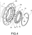
- the invention refers to a rear hub system (1) of a bicycle. Specifically, it relates to the connecting mechanism (5) of the body (2) and the freehub body (4) of a rear hub (1) of a bicycle as seen in Figures 2 , 3 and 4 .
- FIGS 1 and 1A show an exploded view and a locally enlarged view of a rear hub system (1) known as a ratchet system, which comprises, from left to right, a distal stop (1a), a body (2), an axle (3) with wheel bearings (11, 12), a freehub body (4) and a proximal stop (1b).
- the rear hub (1) between the body (2) and the freehub body (4) comprises a connecting part (5a) and a freewheel system (6).
- the freewheel system (6) works through the interaction between the connecting part (5a), which is normally externally threaded and has internal splines, and the two rings (6a, 6b) facing each other, with external splines and laterally toothed with equal and complementary lateral teeth, pushed by two springs (6c) external to them, which make up the freewheel system (6) as shown in Figure 1A .
- the connecting part (5a) which is normally threaded externally for fastening to the body (2) and internally splined for holding the freewheel system (6), is the most important part in the connection and fastening of the freehub body (4) to the body (2).
- the invention refers to a bicycle wheel rear hub (1) that also comprises a first cylindrical body (2) that surrounds an axle (3) and where at a distal end (2a) it comprises a distal stop (1a) and at a proximal end (2b) a freehub body (4) is attached by means of a connecting mechanism (5), where the freehub body (4) comprises a second cylindrical body, a freewheel system (6) within it and a proximal stop (1b) at a proximal end (4b) of the freehub body (4).
- the rear hub (1) of the invention is characterized in that the connecting mechanism (5) between the first body (2) and the freewheel system (6) comprises a connecting crown (7) and an elastic ring (8), which are the key innovative parts of the invention.
- the connecting crown (7) comprises an external crenellated and/or splined surface (7a), an inner radially toothed surface (7b) and a lateral surface (7c).
- the external crenellated and/or splined surface (7a) and the internal toothed surface (7b) act as a support and link between the body (2) of the hub (1) and the rings (6a, 6b) of the freehub body (4) responsible for the effect of the freewheel system (6), ensuring the solidity and firmness necessary for holding the freehub body (4), by means of a sliding adjustment.
- the outer surface (7a) and inner surface (7b) require shapes which may be regular or irregular, but which must be complementary to the surfaces with which they are going to be matched.
- the lateral surface (7c) comprises a circular recess (9) where the elastic ring (8) is attached or seated.
- the crenellated and/or splined outer surface (7a) of the connecting crown (7) is complementary to the inner surface (2c) of the body (2), while the inner radial surface (7b) of the connecting crown (7) is toothed and complementary to the outer surface of the ring (6a) of the freewheel system (6) as seen in Figure 3 .
- the elastic ring (8) of the rear hub (1) of the invention comprises a circular flat body with two free ends (8a, 8b) so as to be able to expand towards the inner surface (2c) of the body (2) and fit into a groove or channel (2d) in the inner radial surface (2c) of the proximal end (2b) of the body (2) of the hub (1) and block the sliding movement of the connecting crown (7), guaranteeing the absolute immobility of the connecting crown (7) inside the body (2).
- the free end (8b) comprises a tab (10) that facilitates the extraction of the elastic ring (8) from the body (2) when it is seated and expanded in the groove (2d) of the inner surface (2c) of the body (2).
- the freewheel system (6) comprises at least two moving rings (6a, 6b) that are laterally toothed and have external splines, facing each other, and at least two springs (6c) on the other side from the toothed surface of the rings (6a, 6b), which together with the rotation of the pedals determine the operation of the freewheel system (6).
- the first ring (6a) fits externally with the complementary splines of the inner radial surface (7b) of the connecting crown (7) and the second ring (6b) fits laterally with the complementary teeth of the first ring (6a) and externally with the inner surface of the freehub body (4).
- the teeth of the rings (6a, 6b) form a wedge shape, one side being inclined and the other straight.
- the freehub body (4) comprises at least one pawl system on an external surface of the distal end (4a) and the connecting crown (7) comprises an inner radially toothed surface (7b) complementary to the pawls of the freehub body (4).
- the connecting crown (7) comprises a lateral radially toothed surface (7c) complementary to the outer surface of a ring (6b) of the free wheel system (6), where in this case, the use of one of the toothed rings (6a) is eliminated, being the connecting crown (7) the connecting mechanism (5) and ring (6a) at the same time.
- the rear hub (1) of the invention comprises wheel bearings (11, 12) on the axle (3), where the wheel bearings (11) are those located inside the body (2) and the wheel bearings (12) are those located inside the freehub body (4), allowing and helping them to rotate when necessary.
Landscapes
- Engineering & Computer Science (AREA)
- Mechanical Engineering (AREA)
- Axle Suspensions And Sidecars For Cycles (AREA)
Claims (10)
- Fahrradhinterradnabe (1), die einen ersten zylindrischen Körper (2) umfasst, der eine Achse (3) umgibt, wobei die Nabe (1) an einem distalen Ende (2a) einen distalen Anschlag (1a) umfasst und an einem proximalen Ende (2b) einen Freilaufkörper (4) umfasst, der mittels eines Verbindungsmechanismus (5) befestigt ist, wobei der Freilaufkörper (4) einen zweiten zylindrischen Körper umfasst, der ein Freilaufsystem (6) umgibt, und einen proximalen Anschlag (1b) an einem proximalen Ende (4b) des Freilaufkörpers (4), der die Nabe (1) umschließt und befestigt, wobei die Nabe (1) dadurch gekennzeichnet ist, dass:- der Verbindungsmechanismus (5) zwischen dem ersten Körper (2) und dem Freilaufsystem (6) des Freilaufkörpers (4) eine Verbindungskrone (7) und einen elastischen Ring (8) umfasst, wobei die Verbindungskrone (7) eine Seitenfläche (7c) mit einer kreisförmigen Nut (9) umfasst, in die der elastische Ring (8) so eingepasst ist, dass er sich in Richtung der Innenfläche (2c) des ersten Körpers (2) ausdehnen und die Verbindungskrone (7) im Inneren des ersten Körpers (2) fixieren kann.
- Fahrradhinterradnabe (1) nach Anspruch 1, wobei die Verbindungskrone (7) eine zur Innenfläche (2c) des ersten Körpers (2) komplementäre regelmäßige oder unregelmäßige Außenfläche (7a) mit Zinnen und/oder Keilen und eine zur Außenfläche mindestens eines Zahnkranzes (6a) des Freilaufs (6) komplementäre radiale Innenfläche (7b) umfasst.
- Fahrradhinterradnabe (1) nach Anspruch 1, wobei der elastische Ring (8) einen kreisförmigen flachen Körper mit zwei freien Enden (8a, 8b) umfasst, wobei das freie Ende (8b) eine Lasche (10) aufweist.
- Fahrradhinterradnabe (1) nach Anspruch 1, wobei der erste Körper (2) eine Nut oder einen Kanal (2d) am proximalen Ende (2b) der Innenfläche (2c) umfasst.
- Fahrradhinterradnabe (1) nach Anspruch 1, wobei das Freilaufsystem (6) mindestens zwei seitlich einander zugewandte Zahnkränze (6a, 6b) mit zu den Innenflächen der Verbindungskrone (7) und des Freilaufkörpers (4) komplementären Außenverzahnungen oder Außenkeilen umfasst.
- Fahrradhinterradnabe (1) nach Anspruch 1, wobei das Freilaufsystem (6) mindestens ein Sperrklinkensystem an der Außenfläche des distalen Endes (4a) des Freilaufkörpers (4) umfasst.
- Fahrradhinterradnabe (1) nach Anspruch 6, wobei die Verbindungskrone (7) eine regelmäßige oder unregelmäßige Außenfläche (7a) mit Zinnen und/oder Keilen umfasst, die komplementär zur Innenfläche (2c) des
Körpers (2) ist, und eine radiale Innenfläche (7b), die komplementär zur Außenfläche von mindestens einem Sperrklinkensystem im Freilaufkörper (4) ist. - Fahrradhinterradnabe (1) nach Anspruch 1, dadurch gekennzeichnet, dass die mit Zinnen und/oder Keilen versehene Verbindungskrone (7) eine gezahnte Seitenfläche (7c) umfasst, die komplementär zur Außenfläche eines Rings (6b) des Freilaufs (6) ist.
- Fahrradhinterradnabe (1) nach Anspruch 1, wobei der erste Körper (2) mindestens ein Radlager (11) im Inneren umfasst.
- Fahrradhinterradnabe (1) nach Anspruch 1, wobei der Freilaufkörper (4) mindestens ein Radlager (12) im Inneren umfasst.
Priority Applications (3)
| Application Number | Priority Date | Filing Date | Title |
|---|---|---|---|
| ES22383008T ES3037132T3 (en) | 2022-10-20 | 2022-10-20 | Internal connection of a bicycle rear hub |
| EP22383008.4A EP4357153B1 (de) | 2022-10-20 | 2022-10-20 | Innere verbindung einer fahrradhinterradnabe |
| US18/484,046 US20240227440A9 (en) | 2022-10-20 | 2023-10-10 | Internal connection of a bicycle rear hub |
Applications Claiming Priority (1)
| Application Number | Priority Date | Filing Date | Title |
|---|---|---|---|
| EP22383008.4A EP4357153B1 (de) | 2022-10-20 | 2022-10-20 | Innere verbindung einer fahrradhinterradnabe |
Publications (2)
| Publication Number | Publication Date |
|---|---|
| EP4357153A1 EP4357153A1 (de) | 2024-04-24 |
| EP4357153B1 true EP4357153B1 (de) | 2025-06-18 |
Family
ID=84365604
Family Applications (1)
| Application Number | Title | Priority Date | Filing Date |
|---|---|---|---|
| EP22383008.4A Active EP4357153B1 (de) | 2022-10-20 | 2022-10-20 | Innere verbindung einer fahrradhinterradnabe |
Country Status (3)
| Country | Link |
|---|---|
| US (1) | US20240227440A9 (de) |
| EP (1) | EP4357153B1 (de) |
| ES (1) | ES3037132T3 (de) |
Family Cites Families (5)
| Publication number | Priority date | Publication date | Assignee | Title |
|---|---|---|---|---|
| US6123179A (en) * | 1998-02-26 | 2000-09-26 | Kun Teng Industry Co., Ltd | Bicycle freewheel hub |
| WO2000019120A1 (en) * | 1998-09-30 | 2000-04-06 | Taylor Anthony G | Redundant freewheeling bicycle apparatus and method |
| DE19847673A1 (de) * | 1998-10-15 | 2000-04-20 | Dt Swiss Ag | Nabe, insbesondere für Fahrräder u. dgl. |
| US10406856B2 (en) * | 2017-06-05 | 2019-09-10 | Chosen Co., Ltd | Bicycle hub apparatus |
| US11673425B2 (en) * | 2020-11-23 | 2023-06-13 | Tien Hsin Industries Co., Ltd. | Bicycle hub |
-
2022
- 2022-10-20 EP EP22383008.4A patent/EP4357153B1/de active Active
- 2022-10-20 ES ES22383008T patent/ES3037132T3/es active Active
-
2023
- 2023-10-10 US US18/484,046 patent/US20240227440A9/en active Pending
Also Published As
| Publication number | Publication date |
|---|---|
| ES3037132T3 (en) | 2025-09-29 |
| US20240131863A1 (en) | 2024-04-25 |
| US20240227440A9 (en) | 2024-07-11 |
| EP4357153A1 (de) | 2024-04-24 |
Similar Documents
| Publication | Publication Date | Title |
|---|---|---|
| US7044876B2 (en) | Bicycle sprocket having lateral protrusions for use in a multiple sprocket assembly | |
| TW201927629A (zh) | 鏈輪總成 | |
| US7846047B2 (en) | Bicycle sprocket having a thickened spline | |
| US8075065B2 (en) | Quick-tightening system for cycle with tightening torque control | |
| US6497314B2 (en) | Bicycle hub with sliding engagement member and detachable freewheel | |
| EP2452865B1 (de) | Zahnkranzstützstruktur | |
| EP0834450B1 (de) | Zusammenbau eines mehrstufigen Kettenrades für ein Fahrrad zum Befestigen eines Kettenrades auf einer Aussenhülse | |
| US20040142782A1 (en) | Multiple level sprocket support for a bicycle | |
| US11220133B2 (en) | Bicycle component for an at least partially muscle-powered bicycle | |
| US20020067069A1 (en) | Bicycle hub with threaded spacer and detachable freewheel | |
| US7444903B1 (en) | Ratchet wrench having reinforced strength | |
| GB1582793A (en) | Multi-speed freewheel for a bicycle | |
| US20110193406A1 (en) | Tubular portion of bicycle hub | |
| US11199252B2 (en) | Body for bicycle rear wheel hub and cassette adapted to be mounted on the hub by means of such a body | |
| TWI803562B (zh) | 特別適用於自行車之輪轂 | |
| TWI720244B (zh) | 特別適用於自行車的輪轂 | |
| TWI848934B (zh) | 具有兩個整合式部份配置彼此連接以供接頭旋轉的後輪鏈輪配置 | |
| EP4357153B1 (de) | Innere verbindung einer fahrradhinterradnabe | |
| GB1565827A (en) | Hub unit for a bicycle | |
| US4840084A (en) | Freewheel mechanism for bicycles | |
| US7637510B2 (en) | Chuck with gripping mechanism stop | |
| EP4017740B1 (de) | Radnabe | |
| US20230091633A1 (en) | Hub | |
| JP2025035887A (ja) | 人力駆動車用フリーホイール組立体 | |
| JPH0724205Y2 (ja) | 最小動作角を小さくしたレンチ |
Legal Events
| Date | Code | Title | Description |
|---|---|---|---|
| PUAI | Public reference made under article 153(3) epc to a published international application that has entered the european phase |
Free format text: ORIGINAL CODE: 0009012 |
|
| STAA | Information on the status of an ep patent application or granted ep patent |
Free format text: STATUS: THE APPLICATION HAS BEEN PUBLISHED |
|
| AK | Designated contracting states |
Kind code of ref document: A1 Designated state(s): AL AT BE BG CH CY CZ DE DK EE ES FI FR GB GR HR HU IE IS IT LI LT LU LV MC ME MK MT NL NO PL PT RO RS SE SI SK SM TR |
|
| STAA | Information on the status of an ep patent application or granted ep patent |
Free format text: STATUS: REQUEST FOR EXAMINATION WAS MADE |
|
| 17P | Request for examination filed |
Effective date: 20241017 |
|
| RBV | Designated contracting states (corrected) |
Designated state(s): AL AT BE BG CH CY CZ DE DK EE ES FI FR GB GR HR HU IE IS IT LI LT LU LV MC ME MK MT NL NO PL PT RO RS SE SI SK SM TR |
|
| P01 | Opt-out of the competence of the unified patent court (upc) registered |
Free format text: CASE NUMBER: APP_62587/2024 Effective date: 20241125 |
|
| GRAP | Despatch of communication of intention to grant a patent |
Free format text: ORIGINAL CODE: EPIDOSNIGR1 |
|
| STAA | Information on the status of an ep patent application or granted ep patent |
Free format text: STATUS: GRANT OF PATENT IS INTENDED |
|
| INTG | Intention to grant announced |
Effective date: 20250217 |
|
| GRAS | Grant fee paid |
Free format text: ORIGINAL CODE: EPIDOSNIGR3 |
|
| GRAA | (expected) grant |
Free format text: ORIGINAL CODE: 0009210 |
|
| STAA | Information on the status of an ep patent application or granted ep patent |
Free format text: STATUS: THE PATENT HAS BEEN GRANTED |
|
| AK | Designated contracting states |
Kind code of ref document: B1 Designated state(s): AL AT BE BG CH CY CZ DE DK EE ES FI FR GB GR HR HU IE IS IT LI LT LU LV MC ME MK MT NL NO PL PT RO RS SE SI SK SM TR |
|
| REG | Reference to a national code |
Ref country code: GB Ref legal event code: FG4D |
|
| REG | Reference to a national code |
Ref country code: CH Ref legal event code: EP |
|
| REG | Reference to a national code |
Ref country code: DE Ref legal event code: R096 Ref document number: 602022016070 Country of ref document: DE |
|
| REG | Reference to a national code |
Ref country code: CH Ref legal event code: EP |
|
| REG | Reference to a national code |
Ref country code: IE Ref legal event code: FG4D |
|
| REG | Reference to a national code |
Ref country code: ES Ref legal event code: FG2A Ref document number: 3037132 Country of ref document: ES Kind code of ref document: T3 Effective date: 20250929 |
|
| PG25 | Lapsed in a contracting state [announced via postgrant information from national office to epo] |
Ref country code: FI Free format text: LAPSE BECAUSE OF FAILURE TO SUBMIT A TRANSLATION OF THE DESCRIPTION OR TO PAY THE FEE WITHIN THE PRESCRIBED TIME-LIMIT Effective date: 20250618 |
|
| REG | Reference to a national code |
Ref country code: LT Ref legal event code: MG9D |
|
| PG25 | Lapsed in a contracting state [announced via postgrant information from national office to epo] |
Ref country code: NO Free format text: LAPSE BECAUSE OF FAILURE TO SUBMIT A TRANSLATION OF THE DESCRIPTION OR TO PAY THE FEE WITHIN THE PRESCRIBED TIME-LIMIT Effective date: 20250918 Ref country code: GR Free format text: LAPSE BECAUSE OF FAILURE TO SUBMIT A TRANSLATION OF THE DESCRIPTION OR TO PAY THE FEE WITHIN THE PRESCRIBED TIME-LIMIT Effective date: 20250919 |
|
| PG25 | Lapsed in a contracting state [announced via postgrant information from national office to epo] |
Ref country code: BG Free format text: LAPSE BECAUSE OF FAILURE TO SUBMIT A TRANSLATION OF THE DESCRIPTION OR TO PAY THE FEE WITHIN THE PRESCRIBED TIME-LIMIT Effective date: 20250618 |
|
| PG25 | Lapsed in a contracting state [announced via postgrant information from national office to epo] |
Ref country code: HR Free format text: LAPSE BECAUSE OF FAILURE TO SUBMIT A TRANSLATION OF THE DESCRIPTION OR TO PAY THE FEE WITHIN THE PRESCRIBED TIME-LIMIT Effective date: 20250618 |
|
| PG25 | Lapsed in a contracting state [announced via postgrant information from national office to epo] |
Ref country code: RS Free format text: LAPSE BECAUSE OF FAILURE TO SUBMIT A TRANSLATION OF THE DESCRIPTION OR TO PAY THE FEE WITHIN THE PRESCRIBED TIME-LIMIT Effective date: 20250918 |
|
| REG | Reference to a national code |
Ref country code: NL Ref legal event code: MP Effective date: 20250618 |
|
| PG25 | Lapsed in a contracting state [announced via postgrant information from national office to epo] |
Ref country code: LV Free format text: LAPSE BECAUSE OF FAILURE TO SUBMIT A TRANSLATION OF THE DESCRIPTION OR TO PAY THE FEE WITHIN THE PRESCRIBED TIME-LIMIT Effective date: 20250618 |
|
| PG25 | Lapsed in a contracting state [announced via postgrant information from national office to epo] |
Ref country code: NL Free format text: LAPSE BECAUSE OF FAILURE TO SUBMIT A TRANSLATION OF THE DESCRIPTION OR TO PAY THE FEE WITHIN THE PRESCRIBED TIME-LIMIT Effective date: 20250618 |
|
| PG25 | Lapsed in a contracting state [announced via postgrant information from national office to epo] |
Ref country code: PT Free format text: LAPSE BECAUSE OF FAILURE TO SUBMIT A TRANSLATION OF THE DESCRIPTION OR TO PAY THE FEE WITHIN THE PRESCRIBED TIME-LIMIT Effective date: 20251020 |
|
| REG | Reference to a national code |
Ref country code: AT Ref legal event code: MK05 Ref document number: 1803888 Country of ref document: AT Kind code of ref document: T Effective date: 20250618 |
|
| PG25 | Lapsed in a contracting state [announced via postgrant information from national office to epo] |
Ref country code: IS Free format text: LAPSE BECAUSE OF FAILURE TO SUBMIT A TRANSLATION OF THE DESCRIPTION OR TO PAY THE FEE WITHIN THE PRESCRIBED TIME-LIMIT Effective date: 20251018 |
|
| PGFP | Annual fee paid to national office [announced via postgrant information from national office to epo] |
Ref country code: DE Payment date: 20251029 Year of fee payment: 4 |
|
| PG25 | Lapsed in a contracting state [announced via postgrant information from national office to epo] |
Ref country code: AT Free format text: LAPSE BECAUSE OF FAILURE TO SUBMIT A TRANSLATION OF THE DESCRIPTION OR TO PAY THE FEE WITHIN THE PRESCRIBED TIME-LIMIT Effective date: 20250618 Ref country code: SM Free format text: LAPSE BECAUSE OF FAILURE TO SUBMIT A TRANSLATION OF THE DESCRIPTION OR TO PAY THE FEE WITHIN THE PRESCRIBED TIME-LIMIT Effective date: 20250618 |
|
| PGFP | Annual fee paid to national office [announced via postgrant information from national office to epo] |
Ref country code: IT Payment date: 20251031 Year of fee payment: 4 |
|
| PGFP | Annual fee paid to national office [announced via postgrant information from national office to epo] |
Ref country code: FR Payment date: 20251027 Year of fee payment: 4 |
|
| PGFP | Annual fee paid to national office [announced via postgrant information from national office to epo] |
Ref country code: BE Payment date: 20251027 Year of fee payment: 4 |
|
| PG25 | Lapsed in a contracting state [announced via postgrant information from national office to epo] |
Ref country code: CZ Free format text: LAPSE BECAUSE OF FAILURE TO SUBMIT A TRANSLATION OF THE DESCRIPTION OR TO PAY THE FEE WITHIN THE PRESCRIBED TIME-LIMIT Effective date: 20250618 |
|
| PG25 | Lapsed in a contracting state [announced via postgrant information from national office to epo] |
Ref country code: PL Free format text: LAPSE BECAUSE OF FAILURE TO SUBMIT A TRANSLATION OF THE DESCRIPTION OR TO PAY THE FEE WITHIN THE PRESCRIBED TIME-LIMIT Effective date: 20250618 |
|
| PG25 | Lapsed in a contracting state [announced via postgrant information from national office to epo] |
Ref country code: EE Free format text: LAPSE BECAUSE OF FAILURE TO SUBMIT A TRANSLATION OF THE DESCRIPTION OR TO PAY THE FEE WITHIN THE PRESCRIBED TIME-LIMIT Effective date: 20250618 |
|
| PG25 | Lapsed in a contracting state [announced via postgrant information from national office to epo] |
Ref country code: SK Free format text: LAPSE BECAUSE OF FAILURE TO SUBMIT A TRANSLATION OF THE DESCRIPTION OR TO PAY THE FEE WITHIN THE PRESCRIBED TIME-LIMIT Effective date: 20250618 |
|
| PGFP | Annual fee paid to national office [announced via postgrant information from national office to epo] |
Ref country code: ES Payment date: 20251103 Year of fee payment: 4 |
|
| PG25 | Lapsed in a contracting state [announced via postgrant information from national office to epo] |
Ref country code: RO Free format text: LAPSE BECAUSE OF FAILURE TO SUBMIT A TRANSLATION OF THE DESCRIPTION OR TO PAY THE FEE WITHIN THE PRESCRIBED TIME-LIMIT Effective date: 20250618 |