EP4356842B1 - Ultraschalldiagnosevorrichtung und steuerungsverfahren für die ultraschalldiagnosevorrichtung - Google Patents
Ultraschalldiagnosevorrichtung und steuerungsverfahren für die ultraschalldiagnosevorrichtung Download PDFInfo
- Publication number
- EP4356842B1 EP4356842B1 EP23204213.5A EP23204213A EP4356842B1 EP 4356842 B1 EP4356842 B1 EP 4356842B1 EP 23204213 A EP23204213 A EP 23204213A EP 4356842 B1 EP4356842 B1 EP 4356842B1
- Authority
- EP
- European Patent Office
- Prior art keywords
- unit
- compression
- ultrasound
- examination
- diagnostic apparatus
- Prior art date
- Legal status (The legal status is an assumption and is not a legal conclusion. Google has not performed a legal analysis and makes no representation as to the accuracy of the status listed.)
- Active
Links
Images


Classifications
-
- A—HUMAN NECESSITIES
- A61—MEDICAL OR VETERINARY SCIENCE; HYGIENE
- A61B—DIAGNOSIS; SURGERY; IDENTIFICATION
- A61B8/00—Diagnosis using ultrasonic, sonic or infrasonic waves
- A61B8/08—Clinical applications
- A61B8/0891—Clinical applications for diagnosis of blood vessels
-
- A—HUMAN NECESSITIES
- A61—MEDICAL OR VETERINARY SCIENCE; HYGIENE
- A61B—DIAGNOSIS; SURGERY; IDENTIFICATION
- A61B8/00—Diagnosis using ultrasonic, sonic or infrasonic waves
- A61B8/42—Details of probe positioning or probe attachment to the patient
- A61B8/4272—Details of probe positioning or probe attachment to the patient involving the acoustic interface between the transducer and the tissue
- A61B8/429—Details of probe positioning or probe attachment to the patient involving the acoustic interface between the transducer and the tissue characterised by determining or monitoring the contact between the transducer and the tissue
-
- A—HUMAN NECESSITIES
- A61—MEDICAL OR VETERINARY SCIENCE; HYGIENE
- A61B—DIAGNOSIS; SURGERY; IDENTIFICATION
- A61B8/00—Diagnosis using ultrasonic, sonic or infrasonic waves
- A61B8/08—Clinical applications
- A61B8/0833—Clinical applications involving detecting or locating foreign bodies or organic structures
- A61B8/085—Clinical applications involving detecting or locating foreign bodies or organic structures for locating body or organic structures, e.g. tumours, calculi, blood vessels, nodules
-
- A—HUMAN NECESSITIES
- A61—MEDICAL OR VETERINARY SCIENCE; HYGIENE
- A61B—DIAGNOSIS; SURGERY; IDENTIFICATION
- A61B8/00—Diagnosis using ultrasonic, sonic or infrasonic waves
- A61B8/42—Details of probe positioning or probe attachment to the patient
- A61B8/4245—Details of probe positioning or probe attachment to the patient involving determining the position of the probe, e.g. with respect to an external reference frame or to the patient
- A61B8/4263—Details of probe positioning or probe attachment to the patient involving determining the position of the probe, e.g. with respect to an external reference frame or to the patient using sensors not mounted on the probe, e.g. mounted on an external reference frame
-
- A—HUMAN NECESSITIES
- A61—MEDICAL OR VETERINARY SCIENCE; HYGIENE
- A61B—DIAGNOSIS; SURGERY; IDENTIFICATION
- A61B8/00—Diagnosis using ultrasonic, sonic or infrasonic waves
- A61B8/52—Devices using data or image processing specially adapted for diagnosis using ultrasonic, sonic or infrasonic waves
- A61B8/5292—Devices using data or image processing specially adapted for diagnosis using ultrasonic, sonic or infrasonic waves using additional data, e.g. patient information, image labeling, acquisition parameters
-
- A—HUMAN NECESSITIES
- A61—MEDICAL OR VETERINARY SCIENCE; HYGIENE
- A61B—DIAGNOSIS; SURGERY; IDENTIFICATION
- A61B8/00—Diagnosis using ultrasonic, sonic or infrasonic waves
- A61B8/58—Testing, adjusting or calibrating the diagnostic device
Definitions
- the present invention relates to an ultrasound diagnostic apparatus and a control method of an ultrasound diagnostic apparatus for examining a blood vessel of a subject.
- a technique for using a so-called ultrasound diagnostic apparatus to capture an ultrasound image of a blood vessel of a subject while compressing a body surface of the subject with an ultrasound probe, for example, in an examination for checking the presence or absence of so-called lower limb varicose veins, an examination for so-called deep vein thrombosis, and the like.
- a user of the ultrasound diagnostic apparatus requires a certain proficiency level or higher in increasing and reducing a compression force applied by the ultrasound probe and the like.
- JP2016-123794A discloses a technology for determining whether or not a compression state is proper by detecting a compression force applied by an ultrasound probe with a sensor.
- JP2016-042903A discloses a technology for measuring blood pressure using a compression force applied by an ultrasound probe in a case where a degree of deformation of a blood vessel inside a subject reaches a certain value.
- JP2020-512069A discloses a technology for estimating a pressure on a body surface of a subject by an ultrasound probe by analyzing an ultrasound image using a so-called machine learning method, and then determining whether or not a blood vessel is narrowed in a case where a certain pressure is applied to the body surface of the subject.
- JP2006-263128A discloses a technology for calculating an elastic modulus of a blood vessel based on a compression force in a case where a body surface of a subject is compressed using an ultrasound probe.
- the ultrasound diagnostic apparatus has a plurality of examination modes
- JP2016-123794A JP2016-123794A
- JP2016-042903A JP2020-512069A
- JP2006-263128A there may be difficulties in smoothly performing the examination, for example, due to an unintended movement of a hand holding the ultrasound probe when sequentially switching the examination modes during the examination, which hinders the capturing of the ultrasound image.
- the present invention has been made in order to solve such a conventional problem, and an object of the present invention is to provide an ultrasound diagnostic apparatus and a control method of an ultrasound diagnostic apparatus that enable a user to smoothly and appropriately perform an examination.
- an ultrasound diagnostic apparatus that examines a blood vessel of a subject
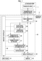
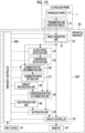
- the ultrasound diagnostic apparatus comprising: an ultrasound probe; an image acquisition unit that continuously acquires an ultrasound image of the blood vessel using the ultrasound probe; a blood vessel detection unit that detects the blood vessel from the ultrasound image; an examination site discrimination unit that discriminates an examination site; an examination mode setting unit that sets an examination mode corresponding to the examination site discriminated by the examination site discrimination unit; a compression detection unit that detects a compression motion on a body surface of the subject by the ultrasound probe; a compression motion determination unit that determines whether or not the compression motion detected by the compression detection unit is proper for the examination mode set by the examination mode setting unit; and a notification unit that notifies a user of a determination result by the compression motion determination unit. Therefore, the user can smoothly and appropriately perform an examination.
- the transmission and reception circuit 12 and the image generation unit 21 constitute an image acquisition unit 32.
- the image generation unit 21, the display controller 22, the blood vessel detection unit 24, the compression detection unit 25, the examination site discrimination unit 26, the examination mode setting unit 27, the compression motion determination unit 28, the notification unit 29, and the main body controller 30 constitute a processor 33 for the apparatus main body 2.
- each ultrasound transducer is composed of a piezoelectric body consisting of a piezoelectric ceramic represented by lead zirconate titanate (PZT), a polymer piezoelectric element represented by poly vinylidene di fluoride (PVDF), a piezoelectric single crystal represented by lead magnesium niobate-lead titanate (PMN-PT), or the like, and electrodes formed at both ends of the piezoelectric body.
- PZT lead zirconate titanate
- PVDF polymer piezoelectric element represented by poly vinylidene di fluoride
- PMN-PT lead magnesium niobate-lead titanate
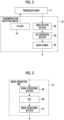
- the signal processing section 45 generates a B-mode image signal, which is tomographic image information regarding tissues inside the subject, by performing, on the sound ray signal received from the transmission and reception circuit 12, correction of the attenuation due to the distance according to the depth of the reflection position of the ultrasound wave using a sound velocity value set by the main body controller 30 and then performing envelope detection processing.
- the image processing section 47 performs various types of necessary image processing such as gradation processing on the B-mode image signal input from the DSC 46 and then sends out the B-mode image signal to the display controller 22, the blood vessel detection unit 24, and the examination site discrimination unit 26.
- the B-mode image signal that has been subjected to image processing by the image processing section 47 is referred to as an ultrasound image.
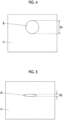
- an ultrasound image U showing a blood vessel B inside the subject is acquired.
- the ultrasound image U showing a short-axis image of the blood vessel B is simply referred to as the ultrasound image U showing the blood vessel B.
- the short-axis image of the blood vessel B refers to a cross section of the blood vessel B perpendicular to a running direction of the blood vessel B.
- the display controller 22 performs predetermined processing on the ultrasound image or the like generated by the image generation unit 21 and displays the ultrasound image or the like on the monitor 23, under the control of the main body controller 30.
- the input device 31 accepts an input operation from an examiner and sends out input information to the main body controller 30.
- the input device 31 is composed of, for example, a device for the examiner to perform an input operation, such as a keyboard, a mouse, a trackball, a touchpad, or a touch panel.
- the compression detection unit 25 can calculate, for example, a ratio R2/R1 between a diameter R1 in the depth direction of the blood vessel B in a state in which no compression is applied by the ultrasound probe 1 and a diameter R2 in the depth direction of the blood vessel B in a state in which compression is applied by the ultrasound probe 1 to detect the compression motion in a case where the ratio R2/R1 is equal to or less than a predetermined ratio threshold value.
- the compression detection unit 25 can send out, for example, the ratio R2/R1 to the compression motion determination unit 28 as a compression motion indicator representing the magnitude of the compression motion by the ultrasound probe 1.
- the examination site discrimination unit 26 analyzes the ultrasound image U generated by the image generation unit 21 to discriminate an examination site captured in the ultrasound image U, such as an upper limb, a lower limb, or a neck, for example.
- the examination site discrimination unit 26 can detect, for example, a target such as the vein, the artery, the bone, and the muscle shown in the ultrasound image U to discriminate the examination site based on the disposition position and the size of the detected target.
- the examination site discrimination unit 26 stores a plurality of template images showing the target, such as the vein, the artery, the bone, and the muscle, and can detect the disposition position and the size of the target using a so-called template matching method of searching the inside of the ultrasound image U using these template images.
- the examination site discrimination unit 26 can further store in advance a plurality of combinations of the disposition position and the size of the target such as the vein, the artery, the bone, and the muscle, and the examination site to discriminate the examination site by fitting the disposition position and the size of the detected target to the stored combination.
- the examination site discrimination unit 26 can also perform the detection of the target such as the vein, the artery, the bone, and the muscle, and the discrimination of the examination site by using a trained model in so-called machine learning, which has learned in advance a large number of ultrasound images U showing the target such as the vein, the artery, the bone, and the muscle, and a large number of combinations of the disposition position and the size of the target such as the vein, the artery, the bone, and the muscle, and the examination site.
- machine learning so-called machine learning
- the examination site discrimination unit 26 can analyze, for example, a plurality of continuous frames of ultrasound images U generated by the image generation unit 21 to detect organs shown in the plurality of frames of ultrasound images U, thereby discriminating the examination site based on the movement of the detected organs.
- the examination site discrimination unit 26 can discriminate the examination site using template matching or a trained model in machine learning.
- the examination site discrimination unit 26 can also discriminate the examination site based on, for example, text information, a so-called schema image, or the like input from a user via the input device 31.
- the examination site discrimination unit 26 can also sequentially recognize the types of sites of the subject imaged in the ultrasound image U to discriminate the examination site based on the order of the recognized sites.
- the examination mode setting unit 27 sets an examination mode corresponding to the examination site discriminated by the examination site discrimination unit 26.
- the examination mode corresponding to the examination site is, for example, a mode having imaging conditions such as a gain and a depth corresponding to the examination site in order to enable clear observation of the examination site.
- the examination mode setting unit 27 can set a vein search mode as the examination mode in a case where the examination site is discriminated to be the upper limb by the examination site discrimination unit 26.
- the examination mode setting unit 27 can set, for example, a thrombosis determination mode as the examination mode in a case where the examination site is discriminated to be the lower limb by the examination site discrimination unit 26.
- the examination mode setting unit 27 can set an elastic modulus measurement mode as the examination mode in a case where the examination site is discriminated to be the neck by the examination site discrimination unit 26.
- an appropriate compression motion by the ultrasound probe 1 differs for each examination site such as the upper limb, the lower limb, and the neck, criteria for determining whether or not the compression motion is proper differ depending on the examination mode, as will be described below.
- the compression motion determination unit 28 determines whether or not the compression motion detected by the compression detection unit 25 is proper for the examination mode set by the examination mode setting unit 27.
- the compression motion determination unit 28 has a predetermined allowable range of the compression motion for each examination mode, and determines whether or not the compression motion is proper by comparing the compression motion detected by the compression detection unit 25 with the allowable range corresponding to the examination mode set by the examination mode setting unit 27.
- the notification unit 29 notifies the user of the determination result by the compression motion determination unit 28.
- the notification unit 29 can notify the user, for example, by displaying the determination result by the compression motion determination unit 28 on the monitor 23.
- step S1 continuous acquisition of the ultrasound images U showing the blood vessel B of the subject in a state in which the user disposes the ultrasound probe 1 on the body surface of the subject is started.
- the transducer array 11 of the ultrasound probe 1 transmits the ultrasound beam into the subject and receives the ultrasound echo from the inside of the subject, thereby generating the reception signal.
- the transmission and reception circuit 12 of the image acquisition unit 32 performs so-called reception focus processing on the reception signal to generate the sound ray signal, under the control of the main body controller 30.
- the sound ray signal generated by the transmission and reception circuit 12 is sent out to the image generation unit 21.
- the image generation unit 21 generates the ultrasound image U using the sound ray signal sent out from the transmission and reception circuit 12.
- the examination site discrimination unit 26 can detect, for example, a target such as the vein, the artery, the bone, and the muscle shown in the ultrasound image U to discriminate the examination site based on the disposition position and the size of the detected target.
- the examination site discrimination unit 26 can also analyze, for example, a plurality of continuous frames of ultrasound images U generated by the image generation unit 21 to detect organs shown in the plurality of frames of ultrasound images U, thereby discriminating the examination site based on the movement of the detected organs.
- the examination site discrimination unit 26 can also discriminate the examination site based on, for example, text information, a so-called schema image, or the like input from a user via the input device 31.
- the examination site discrimination unit 26 can also sequentially recognize the types of sites of the subject captured in the ultrasound image U to discriminate the examination site based on the order of the recognized sites, for example, in a case where the subject is examined according to a predetermined examination protocol.
- the examination mode setting unit 27 sets the examination mode corresponding to the examination site discriminated in step S3.
- the examination mode setting unit 27 can set the vein search mode as the examination mode in a case where the examination site is discriminated to be the upper limb, can set the thrombosis determination mode as the examination mode in a case where the examination site is discriminated to be the lower limb, and can set the elastic modulus measurement mode as the examination mode in a case where the examination site is discriminated to be the neck.
- step S5 the compression detection unit 25 detects the compression motion on the body surface of the subject by the ultrasound probe 1 based on, for example, the change in the diameter in the depth direction of the blood vessel B detected in step S2.
- the compression detection unit 25 can calculate, for example, the ratio R2/R1 between the diameter R1 in the depth direction of the blood vessel B in a state in which no compression is applied by the ultrasound probe 1 and the diameter R2 in the depth direction of the blood vessel B in a state in which compression is applied by the ultrasound probe 1 to detect the compression motion in a case where the ratio R2/R1 is equal to or less than a predetermined ratio threshold value.
- step S6 the compression motion determination unit 28 determines whether or not the compression motion detected in step S5 is proper for the examination mode set in step S4.
- the compression motion determination unit 28 has, for example, a predetermined allowable range of the compression motion for each examination mode, and determines whether or not the compression motion is proper by comparing the compression motion detected in step S5 with the allowable range corresponding to the examination mode set in step S4.
- the compression motion determination unit 28 can determine whether or not the compression motion is proper by using the ratio R2/R1 calculated in step S5 as the compression motion indicator representing the magnitude of the compression motion by the ultrasound probe 1 to compare the ratio R2/R1 with the predetermined proper range of values for each examination mode for the ratio R2/R1.
- step S8 the main body controller 30 determines whether or not to end the examination.
- the main body controller 30 can determine to end the examination, for example, in a case where an instruction to end the examination is input from the user via the input device 31. Further, the main body controller 30 can determine to continue the examination, for example, in a case where no instruction to end the examination is input from the user via the input device 31.
- steps S2 to S8 are repeated as long as it is determined in step S8 to continue the examination.
- the examination mode corresponding to the new examination site is automatically set in step S4, and it is automatically determined in step S6 whether or not the compression motion by the ultrasound probe 1 is proper for this new examination mode. Therefore, the user can perform the compression motion suitable for the examination site while smoothly proceeding with the examination, for example, because there is no need to manually switch the examination modes even in a case where the examination site is changed in the middle of the examination.
- the examination site discrimination unit 26 automatically discriminates the examination site, the examination mode corresponding to the examination site discriminated by the examination mode setting unit 27 is automatically set, the compression detection unit 25 detects the compression motion on the body surface of the subject by the ultrasound probe 1, the compression motion determination unit 28 determines whether or not the compression motion is proper for the set examination mode, and the notification unit 29 notifies the user of the determination result. Therefore, the user can easily perform the compression motion suitable for the examination site by applying the compression to the body surface of the subject using the ultrasound probe 1 while confirming the determination result obtained through the notification from the notification unit 29 without the need to manually switch the examination modes even in a case where the examination site is changed in the middle of the examination. As a result, the user can smoothly and appropriately perform the examination.
- the transmission and reception circuit 12 is provided in the ultrasound probe 1, the transmission and reception circuit 12 may be provided in the apparatus main body 2.
- the image generation unit 21 is provided in the apparatus main body 2, the image generation unit 21 may be provided in the ultrasound probe 1.
- the apparatus main body 2 may be a so-called stationary type, a portable type that is easy to carry, or a so-called handheld type that is composed of, for example, a smartphone or a tablet type computer.
- the type of the device that constitutes the apparatus main body 2 is not particularly limited.
- the notification unit 29 notifies the user by displaying the determination result of the compression motion determination unit 28 on the monitor 23, the method of notifying the user is not limited to this.
- the notification unit 29 can also notify the user of the determination result of the compression motion determination unit 28 by sound via the speaker.
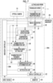
- Fig. 7 shows a configuration of an ultrasound diagnostic apparatus of Embodiment 2.
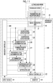
- the ultrasound diagnostic apparatus of Embodiment 2 further comprises an optical camera 51 and comprises an apparatus main body 2A instead of the apparatus main body 2, with respect to the ultrasound diagnostic apparatus of Embodiment 1 shown in Fig. 1 .
- the apparatus main body 2A further comprises an examination site thickness recognition unit 52 and comprises a main body controller 30A instead of the main body controller 30, with respect to the apparatus main body 2 in Embodiment 1.
- the compression detection unit 25, the examination site discrimination unit 26, the examination site thickness recognition unit 52, and the main body controller 30A are connected to the optical camera 51.
- the examination site thickness recognition unit 52 is connected to the compression motion determination unit 28 and the main body controller 30A.
- the image generation unit 21, the display controller 22, the blood vessel detection unit 24, the compression detection unit 25, the examination site discrimination unit 26, the examination mode setting unit 27, the compression motion determination unit 28, the notification unit 29, the main body controller 30A, and the examination site thickness recognition unit 52 constitute a processor 33A for the apparatus main body 2A.
- the optical camera 51 includes, for example, an image sensor, such as a so-called charge coupled device (CCD) image sensor or a so-called complementary metal-oxide-semiconductor (CMOS) image sensor, and images the body surface of the subject and the ultrasound probe 1 disposed on the body surface of the subject to acquire an optical image.
- the optical camera 51 sends out the acquired optical image to the compression detection unit 25 and the examination site thickness recognition unit 52.
- CCD charge coupled device
- CMOS complementary metal-oxide-semiconductor
- the compression detection unit 25 can analyze the optical image acquired by the optical camera 51 to detect the compression motion based on a degree of depression of the body surface of the subject in the optical image or a movement of the arm of the user holding the ultrasound probe 1 and to calculate the compression motion indicator representing the magnitude of the compression motion.
- the compression detection unit 25 can detect the compression motion using, for example, a trained model that has learned in advance a relationship between the degree of depression of the body surface of the subject in the optical image and the compression motion, or a relationship between the movement of the arm of the user holding the ultrasound probe 1 and the compression motion.
- the examination mode setting unit 27 sets the examination mode corresponding to the examination site discriminated based on the optical image by the examination site discrimination unit 26 in this manner.
- the compression motion determination unit 28 determines whether or not the compression motion is proper based on the compression motion detected by the compression detection unit 25 based on the optical image, and the examination mode set by the examination mode setting unit 27.
- the thickness of the examination site is often proportional to the thickness of the blood vessel B at the examination site.
- the compression motion determination unit 28 can adjust the allowable range of the compression motion according to the thickness of the examination site recognized by the examination site thickness recognition unit 52.
- the examination site thickness recognition unit 52 can set a larger allowable range of the compression motion as the examination site is thicker, and can set a smaller allowable range of the compression motion as the examination site is thinner. As a result, the compression motion determination unit 28 can more accurately determine whether or not the compression motion is proper for the subject currently being examined.
- the compression motion determination unit 28 determines whether or not the compression motion is proper for the set examination mode, and the notification unit 29 notifies the user of the determination result, in the same manner as a case where the detection of the compression motion and the discrimination of the examination site are performed based on the ultrasound image U as in the ultrasound diagnostic apparatus of Embodiment 1 even in a case where the detection of the compression motion and the discrimination of the examination site are performed based on the optical image. Therefore, the user can smoothly and appropriately perform the examination.
- the compression motion determination unit 28 can adjust the allowable range of the compression motion according to the thickness of the examination site recognized by the examination site thickness recognition unit 52 to improve the accuracy of the determination as to whether the compression motion is proper, the user can more accurately perform the examination.
- the ultrasound diagnostic apparatus of the embodiment of the present invention can also detect the compression motion by projecting a so-called moire pattern onto the body surface of the subject.
- Fig. 8 shows a configuration of an ultrasound diagnostic apparatus of Embodiment 3.
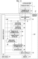
- the ultrasound diagnostic apparatus of Embodiment 3 further comprises the optical camera 51 and a projection mapping device 53 and comprises an apparatus main body 2B instead of the apparatus main body 2, with respect to the ultrasound diagnostic apparatus of Embodiment 1 shown in Fig. 1 .
- the apparatus main body 2B comprises a main body controller 30B instead of the main body controller 30 with respect to the apparatus main body 2 in Embodiment 1.
- the compression detection unit 25 and the main body controller 30B are connected to the optical camera 51.
- the projection mapping device 53 is connected to the main body controller 30B.
- the image generation unit 21, the display controller 22, the blood vessel detection unit 24, the compression detection unit 25, the examination site discrimination unit 26, the examination mode setting unit 27, the compression motion determination unit 28, the notification unit 29, and the main body controller 30B constitute a processor 33B for the apparatus main body 2B.
- the projection mapping device 53 is composed of a so-called projector and projects a moire pattern onto the body surface of the subject. In a case where the body surface of the subject is compressed by the ultrasound probe 1 in a state in which the moire pattern is projected onto the body surface of the subject in this manner, the shape of the moire pattern changes.
- the optical camera 51 acquires the optical image showing the body surface of the subject on which the moire pattern is projected by the projection mapping device 53 and the ultrasound probe 1 disposed on the body surface of the subject.
- the compression detection unit 25 can analyze a plurality of continuous frames of optical images acquired by the optical camera 51 to detect the compression motion based on the change in the moire pattern projected onto the body surface of the subject by the projection mapping device 53 and to calculate the compression motion indicator representing the magnitude of the compression motion.
- the compression detection unit 25 can detect the compression motion from the change in the moire pattern by using, for example, a trained model that has learned in advance a relationship between the change in the moire pattern projected onto the body surface of the subject and the compression motion.
- the compression motion determination unit 28 determines whether or not the compression motion is proper based on the compression motion detected by the compression detection unit 25 based on the change in the moire pattern on the body surface of the subject in this manner, and the examination mode set by the examination mode setting unit 27.
- the notification unit 29 notifies the user of the determination result by the compression motion determination unit 28.
- the compression motion determination unit 28 determines whether or not the compression motion is proper, and the notification unit 29 notifies the user of the determination result even in a case where the compression detection unit 25 detects the compression motion based on the change in the moire pattern projected onto the body surface of the subject. Therefore, the user can smoothly and appropriately perform the examination in the same manner as in the ultrasound diagnostic apparatus of Embodiment 1.
- the ultrasound diagnostic apparatus of Embodiment 3 has a configuration in which the optical camera 51 and the projection mapping device 53 are added to the ultrasound diagnostic apparatus of Embodiment 1, a configuration can also be employed in which the projection mapping device 53 is added to the ultrasound diagnostic apparatus of Embodiment 2.
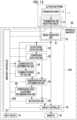
- the compression sensor 54 is connected to the compression detection unit 25 and the main body controller 30. Further, the image generation unit 21, the display controller 22, the blood vessel detection unit 24, the compression detection unit 25, the examination site discrimination unit 26, the examination mode setting unit 27, the compression motion determination unit 28, the notification unit 29, and the main body controller 30C constitute a processor 33C for the apparatus main body 2C.
- the compression sensor 54 is composed of a pressure sensor that detects a pressure applied to a tip part of the ultrasound probe 1 or a so-called acceleration sensor, and changes the output value according to the compression motion on the body surface of the subject by the ultrasound probe 1.
- the compression detection unit 25 detects the compression motion based on the change in the output value of the compression sensor 54 and calculates the compression motion indicator representing the magnitude of the compression motion.
- the compression motion determination unit 28 determines whether or not the compression motion is proper based on the compression motion detected by the compression detection unit 25 based on the change in the output value of the compression sensor 54, and the examination mode set by the examination mode setting unit 27.
- the notification unit 29 notifies the user of the determination result by the compression motion determination unit 28.
- the ultrasound diagnostic apparatus of the embodiment of the present invention can also improve the accuracy of the examination by performing the processing corresponding to the specified subject and user.
- Fig. 10 shows a configuration of an ultrasound diagnostic apparatus of Embodiment 5.
- the ultrasound diagnostic apparatus of Embodiment 5 comprises an apparatus main body 2D instead of the apparatus main body 2 with respect to the ultrasound diagnostic apparatus of Embodiment 1 shown in Fig. 1 .
- the apparatus main body 2D further comprises a subject specification unit 55 and a user specification unit 56 and comprises a main body controller 30D instead of the main body controller 30, with respect to the apparatus main body 2 in Embodiment 1.
- the notification unit 29 notifies the user of a message corresponding to the user specified by the user specification unit 56.
- the notification unit 29 can alert the user by displaying, for example, a message such as "Please apply a firm compression force" on the monitor 23.
- the notification unit 29 can display such a message on the monitor 23 in a case where the proficiency level of the user is lower than a certain level, and can also stop displaying the message in a case where the proficiency level of the user is equal to or higher than a certain level.
- the user can accurately perform the compression motion by confirming the message displayed by the notification unit 29 in this manner.
- the determination operation stop unit 58 stops the operation of the determination by the compression motion determination unit 28 based on the proficiency level of the user discriminated by the proficiency level discrimination unit 57.
- the determination operation stop unit 58 can stop the operation of the determination by the compression motion determination unit 28, for example, in a case where the user is discriminated to have a certain proficiency level or higher by the proficiency level discrimination unit 57.
- the proficiency level discrimination unit 57 automatically discriminates the proficiency level of the user
- the determination operation stop unit 58 stops the operation of the determination by the compression motion determination unit 28 according to the discriminated proficiency level of the user. Therefore, it is possible to save the calculation load and the power required for the processing of the compression motion determination unit 28 particularly in a case where a user with a high proficiency level performs the examination.
- the proficiency level discrimination unit 57 discriminates the proficiency level of the user based on a plurality of continuous frames of ultrasound images U
- the method of discriminating the proficiency level of the user is not limited to this.
- the ultrasound diagnostic apparatus comprises the optical camera 51
- the proficiency level discrimination unit 57 can discriminate the proficiency level of the user by analyzing a plurality of continuous frames of optical images acquired by the optical camera 51 and recognizing the user's technique.
- the proficiency level discrimination unit 57 can discriminate the proficiency level of the user from the plurality of continuous frames of optical images by using, for example, a trained model that has learned in advance a relationship between the user's technique represented by the plurality of continuous frames of optical images and the proficiency level of the user.
- the ultrasound diagnostic apparatus of Embodiment 6 has a configuration in which the proficiency level discrimination unit 57 and the determination operation stop unit 58 are added to the ultrasound diagnostic apparatus of Embodiment 1, a configuration can also be employed in which the proficiency level discrimination unit 57 and the determination operation stop unit 58 are added to the ultrasound diagnostic apparatuses of Embodiments 2 to 5.
- the ultrasound diagnostic apparatus of the embodiment of the present invention can also determine whether or not the compression motion is proper in consideration of the muscle mass of the subject.
- Fig. 12 shows a configuration of an ultrasound diagnostic apparatus of Embodiment 7.
- the ultrasound diagnostic apparatus of Embodiment 7 comprises an apparatus main body 2F instead of the apparatus main body 2 with respect to the ultrasound diagnostic apparatus of Embodiment 1 shown in Fig. 1 .
- the apparatus main body 2F further comprises a muscle mass recognition unit 59 and comprises a main body controller 30F instead of the main body controller 30, with respect to the apparatus main body 2 in Embodiment 1.
- the muscle mass recognition unit 59 is connected to the image generation unit 21.
- the muscle mass recognition unit 59 is connected to the compression motion determination unit 28 and the main body controller 30F.
- the image generation unit 21, the display controller 22, the blood vessel detection unit 24, the compression detection unit 25, the examination site discrimination unit 26, the examination mode setting unit 27, the compression motion determination unit 28, the notification unit 29, the main body controller 30F, and the muscle mass recognition unit 59 constitute a processor 33F for the apparatus main body 2F.
- the muscle mass recognition unit 59 recognizes the muscle mass of the subject by analyzing the ultrasound image U generated by the image generation unit 21.
- the muscle mass recognition unit 59 can recognize the muscle mass of the subject, for example, by detecting the muscle layer shown in the ultrasound image U using a template matching method or the like and measuring the thickness thereof.
- the muscle mass recognition unit 59 can also recognize the muscle mass of the subject from the ultrasound image U by using a trained model that has learned in advance a relationship between a large number of ultrasound images U showing the muscle layer of the subject and the muscle mass of the subject.
- the compression motion determination unit 28 adjusts the allowable range of the compression motion according to the muscle mass of the subject recognized by the muscle mass recognition unit 59.
- the compression motion determination unit 28 can set a larger allowable range of the compression motion as the muscle mass of the subject increases, and can set a smaller allowable range of the compression motion as the muscle mass of the subject decreases. As a result, the compression motion determination unit 28 can more accurately determine whether or not the compression motion is proper in consideration of the actual muscle mass of the subject.
- the muscle mass recognition unit 59 recognizes the muscle mass of the subject from the ultrasound image U, and the compression motion determination unit 28 adjusts the allowable range of the compression motion according to the muscle mass recognized by the muscle mass recognition unit 59. Therefore, the accuracy of the determination as to whether or not the compression motion is proper can be improved, and the user can smoothly and appropriately perform the examination.
- the ultrasound diagnostic apparatus of Embodiment 7 has a configuration in which the muscle mass recognition unit 59 is added to the ultrasound diagnostic apparatus of Embodiment 1, a configuration can also be employed in which the muscle mass recognition unit 59 is added to the ultrasound diagnostic apparatuses of Embodiments 2 to 6.
- the compression force adjustment recommendation unit 60 recommends adjusting the compression force of the ultrasound probe 1 on the body surface of the subject such that the compression motion falls within the allowable range. For example, in a case where the compression force by the ultrasound probe 1 exceeds the allowable range for the examination site and is strong, the compression force adjustment recommendation unit 60 can recommend reducing the compression force of the ultrasound probe 1. In addition, for example, in a case where the compression force by the ultrasound probe 1 falls below the allowable range for the examination site, the compression force adjustment recommendation unit 60 can recommend increasing the compression force of the ultrasound probe 1.
- the compression force adjustment recommendation unit 60 recommends adjusting the compression force of the ultrasound probe 1 on the body surface of the subject such that the compression motion falls within the allowable range, and the notification unit 29 notifies the user of the adjustment of the compression force recommended by the compression force adjustment recommendation unit 60. Therefore, the user can improve the accuracy of the examination by performing a proper compression motion.
Landscapes
- Health & Medical Sciences (AREA)
- Life Sciences & Earth Sciences (AREA)
- Engineering & Computer Science (AREA)
- Physics & Mathematics (AREA)
- Heart & Thoracic Surgery (AREA)
- Surgery (AREA)
- Pathology (AREA)
- Radiology & Medical Imaging (AREA)
- Biophysics (AREA)
- Biomedical Technology (AREA)
- Veterinary Medicine (AREA)
- Medical Informatics (AREA)
- Molecular Biology (AREA)
- Nuclear Medicine, Radiotherapy & Molecular Imaging (AREA)
- Animal Behavior & Ethology (AREA)
- General Health & Medical Sciences (AREA)
- Public Health (AREA)
- Vascular Medicine (AREA)
- Acoustics & Sound (AREA)
- Computer Vision & Pattern Recognition (AREA)
- Ultra Sonic Daignosis Equipment (AREA)
Claims (18)
- Ultraschalldiagnosevorrichtung, die ein Blutgefäß einer Untersuchungsperson untersucht, wobei die Ultraschalldiagnosevorrichtung umfasst:eine Ultraschallsonde (1);eine Bilderfassungseinheit (32), die so konfiguriert ist, dass sie ein Ultraschallbild des Blutgefäßes unter Verwendung der Ultraschallsonde (1) kontinuierlich erfasst;eine Blutgefäß-Detektionseinheit (24), die so konfiguriert ist, dass sie das Blutgefäß aus dem Ultraschallbild detektiert;eine Untersuchungsstellen-Diskriminierungseinheit (26), die so konfiguriert ist, dass sie eine Untersuchungsstelle diskriminiert;eine Untersuchungsmodus-Einstelleinheit (27), die so konfiguriert ist, dass sie einen Untersuchungsmodus, der der Untersuchungsstelle entspricht, die von der Untersuchungsstellen-Diskriminierungseinheit (26) diskriminiert wurde, einstellt;eine Kompressionsdetektionseinheit (25), die so konfiguriert ist, dass sie eine Kompressionsbewegung auf einer Körperoberfläche der Untersuchungsperson durch die Ultraschallsonde (1) detektiert;eine Kompressionsbewegungs-Bestimmungseinheit (28), die so konfiguriert ist, dass sie bestimmt, ob die von der Kompressionsdetektionseinheit (25) detektierte Kompressionsbewegung für den von der Untersuchungsmodus-Einstelleinheit (27) eingestellten Untersuchungsmodus ordnungsgemäß ist oder nicht; undeine Benachrichtigungseinheit (29), die so konfiguriert ist, dass sie einen Benutzer über ein Bestimmungsergebnis durch die Kompressionsbewegungs-Bestimmungseinheit (28) benachrichtigt.
- Ultraschalldiagnosevorrichtung nach Anspruch 1,
wobei die Untersuchungsstellen-Diskriminierungseinheit (26) so konfiguriert ist, dass sie die Untersuchungsstelle auf der Grundlage des Ultraschallbildes diskriminiert. - Ultraschalldiagnosevorrichtung nach Anspruch 1 oder 2, ferner umfassend:eine optische Kamera (51), die so konfiguriert ist, dass sie die Untersuchungsperson abbildet, und die Ultraschallsonde (1), um ein optisches Bild zu erfassen,wobei die Untersuchungsstellen-Diskriminierungseinheit (26) so konfiguriert ist, dass sie die Untersuchungsstelle auf der Grundlage des optischen Bildes diskriminiert.
- Ultraschalldiagnosevorrichtung nach einem der Ansprüche 1 bis 3,
wobei die Untersuchungsmodus-Einstelleinheit (27) so konfiguriert ist, dass sie einen Venensuchmodus in einem Fall einstellt, in dem die Untersuchungsstelle ein oberes Gliedmaß ist. - Ultraschalldiagnosevorrichtung nach einem der Ansprüche 1 bis 4,
wobei die Untersuchungsmodus-Einstelleinheit (27) so konfiguriert ist, dass sie einen Thrombose-Bestimmungsmodus in einem Fall einstellt, in dem die Untersuchungsstelle ein unteres Gliedmaß ist. - Ultraschalldiagnosevorrichtung nach einem der Ansprüche 1 bis 5,
wobei die Untersuchungsmodus-Einstelleinheit (27) so konfiguriert ist, dass sie einen Elastizitätsmodul-Messmodus in einem Fall einstellt, in dem die Untersuchungsstelle ein Hals ist. - Ultraschalldiagnosevorrichtung nach einem der Ansprüche 1 bis 6,
wobei die Kompressionsdetektionseinheit (25) so konfiguriert ist, dass sie die Kompressionsbewegung auf der Grundlage einer Änderung eines Durchmessers in einer Tiefenrichtung des Blutgefäßes in dem Ultraschallbild detektiert. - Ultraschalldiagnosevorrichtung nach Anspruch 1 oder 2, ferner umfassend:eine optische Kamera (51), die so konfiguriert ist, dass sie die Untersuchungsperson abbildet, und die Ultraschallsonde (1), um ein optisches Bild zu erfassen,wobei die Kompressionsdetektionseinheit (25) so konfiguriert ist, dass sie die Kompressionsbewegung auf der Grundlage eines Grades an Eindrücktiefe der Körperoberfläche der Untersuchungsperson in dem optischen Bild oder einer Bewegung eines Arms des Benutzers detektiert.
- Ultraschalldiagnosevorrichtung nach einem der Ansprüche 1 bis 6, ferner umfassend:eine Projektionsmapping-Vorrichtung (53), die so konfiguriert ist, dass sie ein Moiré-Muster auf die Körperoberfläche der Untersuchungsperson projiziert,wobei die Kompressionsdetektionseinheit (25) so konfiguriert ist, dass sie die Kompressionsbewegung auf der Grundlage einer Änderung des Moiré-Musters, das auf die Körperoberfläche der Untersuchungsperson projiziert wird, detektiert.
- Ultraschalldiagnosevorrichtung nach einem der Ansprüche 1 bis 6, ferner umfassend:einen Drucksensor oder einen Beschleunigungssensor, der an der Ultraschallsonde (1) angebracht ist,wobei die Kompressionsdetektionseinheit (25) so konfiguriert ist, dass sie die Kompressionsbewegung auf der Grundlage einer Änderung eines Ausgabewerts des Drucksensors oder des Beschleunigungssensors detektiert.
- Ultraschalldiagnosevorrichtung nach einem der Ansprüche 1 bis 10,
wobei die Kompressionsbewegungs-Bestimmungseinheit (28) einen vorbestimmten zulässigen Bereich der Kompressionsbewegung für jeden Untersuchungsmodus aufweist und so konfiguriert ist, dass sie durch Vergleichen der von der Kompressionsdetektionseinheit (25) detektierten Kompressionsbewegung mit dem zulässigen Bereich, der dem von der Untersuchungsmodus-Einstelleinheit (27) eingestellten Untersuchungsmodus entspricht, bestimmt, ob die Kompressionsbewegung ordnungsgemäß ist oder nicht. - Ultraschalldiagnosevorrichtung nach Anspruch 11, ferner umfassend:eine Untersuchungsperson-Spezifikationseinheit (55), die so konfiguriert ist, dass sie die Untersuchungsperson als Reaktion auf eine Eingabe von Identifikationsinformationen der Untersuchungsperson spezifiziert,wobei die Kompressionsbewegungs-Bestimmungseinheit (28) so konfiguriert ist, dass sie den zulässigen Bereich gemäß dem Alter und Geschlecht der Untersuchungsperson, die von der Untersuchungsperson-Spezifikationseinheit (55) spezifiziert wurden, anpasst.
- Ultraschalldiagnosevorrichtung nach Anspruch 11, ferner umfassend:eine Muskelmassen-Erkennungseinheit (59), die so konfiguriert ist, dass sie eine Muskelmasse der Untersuchungsperson aus dem Ultraschallbild erkennt,wobei die Kompressionsbewegungs-Bestimmungseinheit (28) so konfiguriert ist, dass sie den zulässigen Bereich gemäß der von der Muskelmassen-Erkennungseinheit (59) erkannten Muskelmasse anpasst.
- Ultraschalldiagnosevorrichtung nach Anspruch 11, ferner umfassend:eine optische Kamera (51), die so konfiguriert ist, dass sie die Untersuchungsperson abbildet, um ein optisches Bild zu erfassen; undeine Untersuchungstellendicke-Erkennungseinheit (52), die so konfiguriert ist, dass sie eine Dicke der Untersuchungstelle aus dem optischen Bild, das von der optischen Kamera (51) erfasst wurde, erkennt,wobei die Kompressionsbewegungs-Bestimmungseinheit (28) so konfiguriert ist, dass sie den zulässigen Bereich gemäß der Dicke der Untersuchungsstelle, die von der Untersuchungsstellendicke-Erkennungseinheit (52) erkannt wurde, anpasst.
- Ultraschalldiagnosevorrichtung nach einem der Ansprüche 11 bis 14, ferner umfassend:eine Kompressionskraftanpassungs-Empfehlungseinheit (60), die so konfiguriert ist, dass sie in einem Fall, in dem durch die Kompressionsbewegungs-Bestimmungseinheit (28) bestimmt wird, dass die Kompressionsbewegung nicht ordnungsgemäß ist, Anpassen einer Kompressionskraft der Ultraschallsonde (1) auf der Körperoberfläche der Untersuchungsperson so empfiehlt, dass die Kompressionsbewegung innerhalb des zulässigen Bereichs liegt,wobei die Benachrichtigungseinheit (29) so konfiguriert ist, dass sie den Benutzer über die Anpassung der von der Kompressionskraftanpassungs-Empfehlungseinheit (60) empfohlenen Kompressionskraft benachrichtigt.
- Ultraschalldiagnosevorrichtung nach einem der Ansprüche 1 bis 15, ferner umfassend:eine Kompetenzniveau-Diskriminierungseinheit (57), die so konfiguriert ist, dass sie ein Kompetenzniveau des Benutzers diskriminiert; undeine Bestimmungsvorgang-Stoppeinheit (58), die so konfiguriert ist, dass sie einen Bestimmungsvorgang durch die Kompressionsbewegungs-Bestimmungseinheit (28) gemäß dem von der Kompetenzniveau-Diskriminierungseinheit (57) diskriminierten Kompetenzniveau des Benutzers stoppt.
- Ultraschalldiagnosevorrichtung nach einem der Ansprüche 1 bis 16, ferner umfassend:eine Benutzerspezifikationseinheit (56), die so konfiguriert ist, dass sie den Benutzer als Reaktion auf eine Eingabe von Identifikationsinformationen des Benutzers spezifiziert,wobei die Benachrichtigungseinheit (29) so konfiguriert ist, dass sie den Benutzer über eine Nachricht, die dem Benutzer entspricht, der von der Benutzerspezifikationseinheit (56) spezifiziert wurde, benachrichtigt.
- Steuerverfahren einer Ultraschalldiagnosevorrichtung, die ein Blutgefäß einer Untersuchungsperson untersucht, wobei das Steuerverfahren umfasst:kontinuierliches Erfassen eines Ultraschallbildes des Blutgefäßes unter Verwendung einer Ultraschallsonde (1);Detektieren des Blutgefäßes aus dem Ultraschallbild;Diskriminieren einer Untersuchungsstelle;Einstellen eines Untersuchungsmodus, der der diskriminierten Untersuchungsstelle entspricht;Detektieren einer Kompressionsbewegung auf einer Körperoberfläche der Untersuchungsperson durch die Ultraschallsonde (1);Bestimmen, ob die für den eingestellten Untersuchungsmodus detektierte Kompressionsbewegung ordnungsgemäß ist oder nicht; undBenachrichtigen eines Benutzers über ein Bestimmungsergebnis.
Applications Claiming Priority (1)
| Application Number | Priority Date | Filing Date | Title |
|---|---|---|---|
| JP2022166347A JP2024058930A (ja) | 2022-10-17 | 2022-10-17 | 超音波診断装置および超音波診断装置の制御方法 |
Publications (3)
| Publication Number | Publication Date |
|---|---|
| EP4356842A1 EP4356842A1 (de) | 2024-04-24 |
| EP4356842B1 true EP4356842B1 (de) | 2025-07-02 |
| EP4356842B8 EP4356842B8 (de) | 2025-09-03 |
Family
ID=88417228
Family Applications (1)
| Application Number | Title | Priority Date | Filing Date |
|---|---|---|---|
| EP23204213.5A Active EP4356842B8 (de) | 2022-10-17 | 2023-10-17 | Ultraschalldiagnosevorrichtung und steuerungsverfahren für die ultraschalldiagnosevorrichtung |
Country Status (3)
| Country | Link |
|---|---|
| US (1) | US20240122571A1 (de) |
| EP (1) | EP4356842B8 (de) |
| JP (1) | JP2024058930A (de) |
Families Citing this family (1)
| Publication number | Priority date | Publication date | Assignee | Title |
|---|---|---|---|---|
| JP7792484B1 (ja) * | 2024-10-02 | 2025-12-25 | ジーイー・プレシジョン・ヘルスケア・エルエルシー | 超音波プローブの操作をガイドするプログラム及び、超音波画像生成システム |
Family Cites Families (15)
| Publication number | Priority date | Publication date | Assignee | Title |
|---|---|---|---|---|
| EP1090582B1 (de) * | 1999-10-01 | 2001-05-23 | Karl Storz GmbH & Co. KG | Bildgebendes Verfahren zum Ermitteln des Zustands von Gewebe |
| JP4627673B2 (ja) | 2005-03-24 | 2011-02-09 | シチズンホールディングス株式会社 | 血管弾性率測定方法及び血管弾性率測定装置 |
| JP4945300B2 (ja) * | 2007-04-25 | 2012-06-06 | 株式会社東芝 | 超音波診断装置 |
| US9610063B2 (en) * | 2010-03-26 | 2017-04-04 | The Johns Hopkins University | Methods and apparatus for ultrasound strain imaging |
| JP5501999B2 (ja) * | 2011-03-08 | 2014-05-28 | 富士フイルム株式会社 | 超音波診断装置および弾性指標信頼性判定方法 |
| TWI494638B (zh) * | 2012-12-12 | 2015-08-01 | Univ Nat Taiwan | 眼壓變化監控系統、其方法及用以感測眼壓變化之隱形眼鏡 |
| JP5701439B1 (ja) | 2014-08-20 | 2015-04-15 | 医療法人 駿東育愛会 望星第一クリニック | 皮下診断装置及び血圧測定方法 |
| US11141179B2 (en) * | 2014-12-11 | 2021-10-12 | Koninklijke Philips N.V. | Setting of sonothromobolysis ultrasound output power |
| JP5920746B1 (ja) * | 2015-01-08 | 2016-05-18 | 学校法人早稲田大学 | 穿刺支援システム |
| GB201703575D0 (en) | 2017-03-06 | 2017-04-19 | Thinksono Ltd | Blood vessel obstruction diagnosis method, apparatus & system |
| US20190239850A1 (en) * | 2018-02-06 | 2019-08-08 | Steven Philip Dalvin | Augmented/mixed reality system and method for the guidance of a medical exam |
| CN114340506B (zh) * | 2019-12-25 | 2024-04-02 | 深圳迈瑞生物医疗电子股份有限公司 | 超声粘弹性测量方法、装置和存储介质 |
| CN117222361A (zh) * | 2021-04-19 | 2023-12-12 | 梅约医学教育与研究基金会 | 根据诱导的解剖流体流动的静脉测试和血管评估 |
| JP2024521977A (ja) * | 2021-04-19 | 2024-06-04 | ヴェインテク ピーティーワイ リミテッド | ポータブル超音波装置及び超音波撮像方法 |
| JP7690799B2 (ja) * | 2021-07-15 | 2025-06-11 | コニカミノルタ株式会社 | 超音波診断装置及びプログラム |
-
2022
- 2022-10-17 JP JP2022166347A patent/JP2024058930A/ja active Pending
-
2023
- 2023-09-22 US US18/472,840 patent/US20240122571A1/en active Pending
- 2023-10-17 EP EP23204213.5A patent/EP4356842B8/de active Active
Also Published As
| Publication number | Publication date |
|---|---|
| JP2024058930A (ja) | 2024-04-30 |
| EP4356842B8 (de) | 2025-09-03 |
| US20240122571A1 (en) | 2024-04-18 |
| EP4356842A1 (de) | 2024-04-24 |
Similar Documents
| Publication | Publication Date | Title |
|---|---|---|
| US12594060B2 (en) | Ultrasound diagnostic apparatus, control method of ultrasound diagnostic apparatus, and processor for ultrasound diagnostic apparatus | |
| EP3865070B1 (de) | Ultraschalldiagnosevorrichtung und verfahren zur steuerung der ultraschalldiagnosevorrichtung | |
| EP3338643B1 (de) | Ultraschalldiagnosevorrichtung und verfahren zur steuerung der ultraschalldiagnosevorrichtung | |
| US12303330B2 (en) | Ultrasound diagnostic apparatus, method for controlling ultrasound diagnostic apparatus, and processor for ultrasound diagnostic apparatus | |
| EP4356842B1 (de) | Ultraschalldiagnosevorrichtung und steuerungsverfahren für die ultraschalldiagnosevorrichtung | |
| US12419569B2 (en) | Swallowing evaluation system and swallowing evaluation method | |
| JP2011072522A (ja) | 超音波診断装置及び方法 | |
| EP4356844A1 (de) | Ultraschalldiagnosevorrichtung und steuerungsverfahren für die ultraschalldiagnosevorrichtung | |
| JP2020048928A (ja) | 超音波診断装置および超音波診断装置の制御方法 | |
| US20240081786A1 (en) | Ultrasound diagnostic apparatus and control method for ultrasound diagnostic apparatus | |
| US20240099686A1 (en) | Ultrasound diagnostic system and control method for ultrasound diagnostic system | |
| JP7690387B2 (ja) | 超音波診断装置および超音波診断装置の制御方法 | |
| US12496045B2 (en) | Ultrasound diagnostic apparatus and control method of ultrasound diagnostic apparatus | |
| US20240108312A1 (en) | Ultrasound diagnostic apparatus and control method for ultrasound diagnostic apparatus | |
| US20240081788A1 (en) | Ultrasound diagnostic apparatus and control method for ultrasound diagnostic apparatus | |
| JP2020048968A (ja) | 超音波診断装置および超音波診断装置の制御方法 | |
| JP2024042416A (ja) | 超音波診断装置および超音波診断装置の制御方法 | |
| JP2026032721A (ja) | 超音波診断装置および超音波診断装置の制御方法 | |
| JP2025134236A (ja) | 超音波診断装置および超音波診断装置の制御方法 |
Legal Events
| Date | Code | Title | Description |
|---|---|---|---|
| PUAI | Public reference made under article 153(3) epc to a published international application that has entered the european phase |
Free format text: ORIGINAL CODE: 0009012 |
|
| STAA | Information on the status of an ep patent application or granted ep patent |
Free format text: STATUS: THE APPLICATION HAS BEEN PUBLISHED |
|
| AK | Designated contracting states |
Kind code of ref document: A1 Designated state(s): AL AT BE BG CH CY CZ DE DK EE ES FI FR GB GR HR HU IE IS IT LI LT LU LV MC ME MK MT NL NO PL PT RO RS SE SI SK SM TR |
|
| STAA | Information on the status of an ep patent application or granted ep patent |
Free format text: STATUS: REQUEST FOR EXAMINATION WAS MADE |
|
| 17P | Request for examination filed |
Effective date: 20241023 |
|
| RBV | Designated contracting states (corrected) |
Designated state(s): AL AT BE BG CH CY CZ DE DK EE ES FI FR GB GR HR HU IE IS IT LI LT LU LV MC ME MK MT NL NO PL PT RO RS SE SI SK SM TR |
|
| GRAP | Despatch of communication of intention to grant a patent |
Free format text: ORIGINAL CODE: EPIDOSNIGR1 |
|
| STAA | Information on the status of an ep patent application or granted ep patent |
Free format text: STATUS: GRANT OF PATENT IS INTENDED |
|
| INTG | Intention to grant announced |
Effective date: 20250227 |
|
| GRAS | Grant fee paid |
Free format text: ORIGINAL CODE: EPIDOSNIGR3 |
|
| GRAA | (expected) grant |
Free format text: ORIGINAL CODE: 0009210 |
|
| STAA | Information on the status of an ep patent application or granted ep patent |
Free format text: STATUS: THE PATENT HAS BEEN GRANTED |
|
| AK | Designated contracting states |
Kind code of ref document: B1 Designated state(s): AL AT BE BG CH CY CZ DE DK EE ES FI FR GB GR HR HU IE IS IT LI LT LU LV MC ME MK MT NL NO PL PT RO RS SE SI SK SM TR |
|
| P01 | Opt-out of the competence of the unified patent court (upc) registered |
Free format text: CASE NUMBER: APP_24695/2025 Effective date: 20250523 |
|
| REG | Reference to a national code |
Ref country code: GB Ref legal event code: FG4D |
|
| REG | Reference to a national code |
Ref country code: CH Ref legal event code: EP |
|
| REG | Reference to a national code |
Ref country code: DE Ref legal event code: R096 Ref document number: 602023004495 Country of ref document: DE |
|
| REG | Reference to a national code |
Ref country code: IE Ref legal event code: FG4D |
|
| REG | Reference to a national code |
Ref country code: CH Ref legal event code: PK Free format text: BERICHTIGUNG B8 |
|
| RAP4 | Party data changed (patent owner data changed or rights of a patent transferred) |
Owner name: FUJIFILM CORPORATION |
|
| PGFP | Annual fee paid to national office [announced via postgrant information from national office to epo] |
Ref country code: FR Payment date: 20250908 Year of fee payment: 3 |
|
| REG | Reference to a national code |
Ref country code: NL Ref legal event code: MP Effective date: 20250702 |
|
| PG25 | Lapsed in a contracting state [announced via postgrant information from national office to epo] |
Ref country code: PT Free format text: LAPSE BECAUSE OF FAILURE TO SUBMIT A TRANSLATION OF THE DESCRIPTION OR TO PAY THE FEE WITHIN THE PRESCRIBED TIME-LIMIT Effective date: 20251103 |
|
| PG25 | Lapsed in a contracting state [announced via postgrant information from national office to epo] |
Ref country code: NL Free format text: LAPSE BECAUSE OF FAILURE TO SUBMIT A TRANSLATION OF THE DESCRIPTION OR TO PAY THE FEE WITHIN THE PRESCRIBED TIME-LIMIT Effective date: 20250702 |
|
| REG | Reference to a national code |
Ref country code: AT Ref legal event code: MK05 Ref document number: 1808326 Country of ref document: AT Kind code of ref document: T Effective date: 20250702 |
|
| PG25 | Lapsed in a contracting state [announced via postgrant information from national office to epo] |
Ref country code: IS Free format text: LAPSE BECAUSE OF FAILURE TO SUBMIT A TRANSLATION OF THE DESCRIPTION OR TO PAY THE FEE WITHIN THE PRESCRIBED TIME-LIMIT Effective date: 20251102 |
|
| PGFP | Annual fee paid to national office [announced via postgrant information from national office to epo] |
Ref country code: DE Payment date: 20250902 Year of fee payment: 3 |
|
| PG25 | Lapsed in a contracting state [announced via postgrant information from national office to epo] |
Ref country code: NO Free format text: LAPSE BECAUSE OF FAILURE TO SUBMIT A TRANSLATION OF THE DESCRIPTION OR TO PAY THE FEE WITHIN THE PRESCRIBED TIME-LIMIT Effective date: 20251002 |
|
| REG | Reference to a national code |
Ref country code: LT Ref legal event code: MG9D |
|
| PG25 | Lapsed in a contracting state [announced via postgrant information from national office to epo] |
Ref country code: AT Free format text: LAPSE BECAUSE OF FAILURE TO SUBMIT A TRANSLATION OF THE DESCRIPTION OR TO PAY THE FEE WITHIN THE PRESCRIBED TIME-LIMIT Effective date: 20250702 |
|
| PG25 | Lapsed in a contracting state [announced via postgrant information from national office to epo] |
Ref country code: FI Free format text: LAPSE BECAUSE OF FAILURE TO SUBMIT A TRANSLATION OF THE DESCRIPTION OR TO PAY THE FEE WITHIN THE PRESCRIBED TIME-LIMIT Effective date: 20250702 |
|
| PG25 | Lapsed in a contracting state [announced via postgrant information from national office to epo] |
Ref country code: HR Free format text: LAPSE BECAUSE OF FAILURE TO SUBMIT A TRANSLATION OF THE DESCRIPTION OR TO PAY THE FEE WITHIN THE PRESCRIBED TIME-LIMIT Effective date: 20250702 |
|
| PG25 | Lapsed in a contracting state [announced via postgrant information from national office to epo] |
Ref country code: GR Free format text: LAPSE BECAUSE OF FAILURE TO SUBMIT A TRANSLATION OF THE DESCRIPTION OR TO PAY THE FEE WITHIN THE PRESCRIBED TIME-LIMIT Effective date: 20251003 |
|
| PG25 | Lapsed in a contracting state [announced via postgrant information from national office to epo] |
Ref country code: SE Free format text: LAPSE BECAUSE OF FAILURE TO SUBMIT A TRANSLATION OF THE DESCRIPTION OR TO PAY THE FEE WITHIN THE PRESCRIBED TIME-LIMIT Effective date: 20250702 Ref country code: CZ Free format text: LAPSE BECAUSE OF FAILURE TO SUBMIT A TRANSLATION OF THE DESCRIPTION OR TO PAY THE FEE WITHIN THE PRESCRIBED TIME-LIMIT Effective date: 20250702 |
|
| PG25 | Lapsed in a contracting state [announced via postgrant information from national office to epo] |
Ref country code: LV Free format text: LAPSE BECAUSE OF FAILURE TO SUBMIT A TRANSLATION OF THE DESCRIPTION OR TO PAY THE FEE WITHIN THE PRESCRIBED TIME-LIMIT Effective date: 20250702 |
|
| PG25 | Lapsed in a contracting state [announced via postgrant information from national office to epo] |
Ref country code: PL Free format text: LAPSE BECAUSE OF FAILURE TO SUBMIT A TRANSLATION OF THE DESCRIPTION OR TO PAY THE FEE WITHIN THE PRESCRIBED TIME-LIMIT Effective date: 20250702 Ref country code: BG Free format text: LAPSE BECAUSE OF FAILURE TO SUBMIT A TRANSLATION OF THE DESCRIPTION OR TO PAY THE FEE WITHIN THE PRESCRIBED TIME-LIMIT Effective date: 20250702 |
|
| PG25 | Lapsed in a contracting state [announced via postgrant information from national office to epo] |
Ref country code: RS Free format text: LAPSE BECAUSE OF FAILURE TO SUBMIT A TRANSLATION OF THE DESCRIPTION OR TO PAY THE FEE WITHIN THE PRESCRIBED TIME-LIMIT Effective date: 20251002 |
|
| PG25 | Lapsed in a contracting state [announced via postgrant information from national office to epo] |
Ref country code: ES Free format text: LAPSE BECAUSE OF FAILURE TO SUBMIT A TRANSLATION OF THE DESCRIPTION OR TO PAY THE FEE WITHIN THE PRESCRIBED TIME-LIMIT Effective date: 20250702 |
|
| PG25 | Lapsed in a contracting state [announced via postgrant information from national office to epo] |
Ref country code: RO Free format text: LAPSE BECAUSE OF FAILURE TO SUBMIT A TRANSLATION OF THE DESCRIPTION OR TO PAY THE FEE WITHIN THE PRESCRIBED TIME-LIMIT Effective date: 20250702 |
|
| PG25 | Lapsed in a contracting state [announced via postgrant information from national office to epo] |
Ref country code: SM Free format text: LAPSE BECAUSE OF FAILURE TO SUBMIT A TRANSLATION OF THE DESCRIPTION OR TO PAY THE FEE WITHIN THE PRESCRIBED TIME-LIMIT Effective date: 20250702 |
|
| PG25 | Lapsed in a contracting state [announced via postgrant information from national office to epo] |
Ref country code: DK Free format text: LAPSE BECAUSE OF FAILURE TO SUBMIT A TRANSLATION OF THE DESCRIPTION OR TO PAY THE FEE WITHIN THE PRESCRIBED TIME-LIMIT Effective date: 20250702 |
|
| PG25 | Lapsed in a contracting state [announced via postgrant information from national office to epo] |
Ref country code: IT Free format text: LAPSE BECAUSE OF FAILURE TO SUBMIT A TRANSLATION OF THE DESCRIPTION OR TO PAY THE FEE WITHIN THE PRESCRIBED TIME-LIMIT Effective date: 20250702 |