EP4355986B1 - Brennstoffkonditionierungssystem und verfahren zur versorgung eines flugzeugturbinenmotors mit brennstoff aus einem kryotank - Google Patents
Brennstoffkonditionierungssystem und verfahren zur versorgung eines flugzeugturbinenmotors mit brennstoff aus einem kryotank Download PDFInfo
- Publication number
- EP4355986B1 EP4355986B1 EP22732256.7A EP22732256A EP4355986B1 EP 4355986 B1 EP4355986 B1 EP 4355986B1 EP 22732256 A EP22732256 A EP 22732256A EP 4355986 B1 EP4355986 B1 EP 4355986B1
- Authority
- EP
- European Patent Office
- Prior art keywords
- fuel
- tank
- compression
- elementary
- conditioning system
- Prior art date
- Legal status (The legal status is an assumption and is not a legal conclusion. Google has not performed a legal analysis and makes no representation as to the accuracy of the status listed.)
- Active
Links
Images


Classifications
-
- B—PERFORMING OPERATIONS; TRANSPORTING
- B64—AIRCRAFT; AVIATION; COSMONAUTICS
- B64D—EQUIPMENT FOR FITTING IN OR TO AIRCRAFT; FLIGHT SUITS; PARACHUTES; ARRANGEMENT OR MOUNTING OF POWER PLANTS OR PROPULSION TRANSMISSIONS IN AIRCRAFT
- B64D37/00—Arrangements in connection with fuel supply for power plant
- B64D37/34—Conditioning fuel, e.g. heating
-
- F—MECHANICAL ENGINEERING; LIGHTING; HEATING; WEAPONS; BLASTING
- F02—COMBUSTION ENGINES; HOT-GAS OR COMBUSTION-PRODUCT ENGINE PLANTS
- F02C—GAS-TURBINE PLANTS; AIR INTAKES FOR JET-PROPULSION PLANTS; CONTROLLING FUEL SUPPLY IN AIR-BREATHING JET-PROPULSION PLANTS
- F02C3/00—Gas-turbine plants characterised by the use of combustion products as the working fluid
- F02C3/20—Gas-turbine plants characterised by the use of combustion products as the working fluid using a special fuel, oxidant, or dilution fluid to generate the combustion products
- F02C3/22—Gas-turbine plants characterised by the use of combustion products as the working fluid using a special fuel, oxidant, or dilution fluid to generate the combustion products the fuel or oxidant being gaseous at standard temperature and pressure
-
- F—MECHANICAL ENGINEERING; LIGHTING; HEATING; WEAPONS; BLASTING
- F02—COMBUSTION ENGINES; HOT-GAS OR COMBUSTION-PRODUCT ENGINE PLANTS
- F02C—GAS-TURBINE PLANTS; AIR INTAKES FOR JET-PROPULSION PLANTS; CONTROLLING FUEL SUPPLY IN AIR-BREATHING JET-PROPULSION PLANTS
- F02C7/00—Features, components parts, details or accessories, not provided for in, or of interest apart form groups F02C1/00 - F02C6/00; Air intakes for jet-propulsion plants
- F02C7/22—Fuel supply systems
- F02C7/232—Fuel valves; Draining valves or systems
-
- F—MECHANICAL ENGINEERING; LIGHTING; HEATING; WEAPONS; BLASTING
- F02—COMBUSTION ENGINES; HOT-GAS OR COMBUSTION-PRODUCT ENGINE PLANTS
- F02C—GAS-TURBINE PLANTS; AIR INTAKES FOR JET-PROPULSION PLANTS; CONTROLLING FUEL SUPPLY IN AIR-BREATHING JET-PROPULSION PLANTS
- F02C9/00—Controlling gas-turbine plants; Controlling fuel supply in air- breathing jet-propulsion plants
- F02C9/26—Control of fuel supply
- F02C9/40—Control of fuel supply specially adapted to the use of a special fuel or a plurality of fuels
-
- F—MECHANICAL ENGINEERING; LIGHTING; HEATING; WEAPONS; BLASTING
- F17—STORING OR DISTRIBUTING GASES OR LIQUIDS
- F17C—VESSELS FOR CONTAINING OR STORING COMPRESSED, LIQUEFIED OR SOLIDIFIED GASES; FIXED-CAPACITY GAS-HOLDERS; FILLING VESSELS WITH, OR DISCHARGING FROM VESSELS, COMPRESSED, LIQUEFIED, OR SOLIDIFIED GASES
- F17C9/00—Methods or apparatus for discharging liquefied or solidified gases from vessels not under pressure
- F17C9/02—Methods or apparatus for discharging liquefied or solidified gases from vessels not under pressure with change of state, e.g. vaporisation
-
- F—MECHANICAL ENGINEERING; LIGHTING; HEATING; WEAPONS; BLASTING
- F17—STORING OR DISTRIBUTING GASES OR LIQUIDS
- F17C—VESSELS FOR CONTAINING OR STORING COMPRESSED, LIQUEFIED OR SOLIDIFIED GASES; FIXED-CAPACITY GAS-HOLDERS; FILLING VESSELS WITH, OR DISCHARGING FROM VESSELS, COMPRESSED, LIQUEFIED, OR SOLIDIFIED GASES
- F17C2270/00—Applications
- F17C2270/01—Applications for fluid transport or storage
- F17C2270/0186—Applications for fluid transport or storage in the air or in space
- F17C2270/0189—Planes
Definitions
- the present invention relates to the field of aircraft comprising turbine engines powered by fuel stored in a cryogenic tank.
- fuel particularly hydrogen
- liquid form to limit the size and mass of aircraft tanks.
- fuel is stored at a temperature of around 20 to 22 Kelvins (-253 to -251°C) in a cryogenic tank on the aircraft.
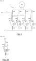
- an SCAA conditioning system comprising a fuel circuit 100 connected at the inlet to a cryogenic tank R1 and at the outlet to the combustion chamber CC of a turbine engine T.
- a fuel flow Q circulating from upstream to downstream in the fuel circuit 100 and successively passes through a mechanical pump 101 and a heating module 102.
- a mechanical pump 101 of the positive displacement or centrifugal type can be used, also called a high pressure pump, which operates at pressures of 50 bars.
- a mechanical pump 101 has many disadvantages in terms of sealing, lubrication and efficiency.
- a mechanical pump 101 requires in particular a significant amount of energy to be able to ensure compression.
- mechanical pumps 101 that can be used with cryogenic tanks do not allow operation over a wide range of flow rate/pressure for high efficiency.
- it is necessary to use a mechanical pump 101 whose operating point is not optimal and which requires moving away from the recommended operating range of said mechanical pump 101, which increases the constraints applied to the mechanical pump 101 and reduces its efficiency.
- Such a mechanical pump 101 cannot therefore adapt its flow rate optimally according to the needs of the turbine engine.
- the document WO2014105335A1 discloses a fuel conditioning system configured to power an aircraft turbine engine according to the prior art.
- the invention thus aims to eliminate at least some of these drawbacks by proposing a new fuel conditioning system allowing compression and heating with better efficiency and greater reliability.
- a system for heating fuel in a container prior to its injection into a buffer tank is also known in the prior art.
- the container is equipped with numerous sensors to enable cold fluid to be added or the container to be emptied in the event of an uncontrolled temperature rise.
- Such an architecture presents a significant risk of backflow at the container outlet given that the buffer tank has a higher pressure than the inlet tank, which affects safety. Also, it is necessary to provide a high-pressure pump which has the aforementioned drawbacks.
- the invention relates to a fuel conditioning system configured to supply an aircraft turbine engine with fuel from a cryogenic tank, the conditioning system comprising a fuel circuit connected at the inlet to the cryogenic tank and at the outlet to the turbine engine, a flow of fuel circulating from upstream to downstream in the fuel circuit.
- Compression is performed isochorically and not solely mechanically, thereby eliminating the drawbacks of a mechanical pump discussed previously.
- isochoric compression allows for taking advantage of the elementary heat sources available in an aeronautical environment to heat the cryogenically stored fuel stream.
- the gas stream expands isenthalpically in the cryogenic tank, thereby balancing the pressures to allow a new safe cycle of use.
- Degassing reduces the pressure to allow the elementary tanks to be filled from the low-pressure cryogenic tank without the need for a high-pressure pump.
- a return circuit allows for maintaining sufficient pressure in the cryogenic tank to supply the elementary tanks even when the fuel level in the cryogenic tank drops over time.
- a buffer tank provides flexibility for the turboshaft engine, which constantly has fuel at a temperature and pressure close to the optimal injection conditions.
- Such a buffer tank can also be filled gradually over time following isochoric compression.
- the compression modules are mounted in parallel so as to independently use various elementary heat sources.
- the conditioning system comprises at least four compression modules to allow them to be used out of phase.
- each elementary heat source provides calories from the turbine engine and/or the aircraft.
- the energy provided comes from available heat sources and is not generated solely for isochoric compression, which improves the energy balance.
- At least one compression module comprises at least two elementary reservoirs mounted in series so as to produce compression stages.
- Each compression module makes it possible to produce progressive compression, which makes it possible to reduce the volume of the elementary reservoirs.
- At least one compression module comprises an intake valve configured to increase the pressure in the elementary tank by placing the elementary tank in communication with the buffer tank.
- the pressurization can be carried out preliminary for the fuel flow leaving the buffer tank and then the pressurization can be finalized by isochoric compression.
- Such a compression module is advantageous when the power of the elementary source is not capable on its own of ensuring the pressure increase.
- Such a compression module is also advantageous when the fuel is taken downstream of an exchanger with a significant heat source, in particular from the turbine engine.
- the conditioning system comprises at least a first exchanger configured to take calories from the gas flow circulating in the return circuit and transmit them to the fuel flow.
- the conditioning system comprises at least one second exchanger, upstream of the compression modules, configured to take calories from a heat source and transmit them to the fuel flow.
- a second exchanger is advantageous for making the fuel flow in the compression modules gaseous.
- the heat source of the second exchanger is a fuel flow taken downstream of the buffer tank, preferably downstream of a third exchanger. A heat supply by heated fuel makes it possible to avoid any condensation which could occur with an air flow.
- the conditioning system comprises at least a third exchanger, downstream of the compression modules, configured to take calories from a heat source and transmit them to the fuel flow prior to its injection into the turbine engine.
- the conditioning system comprises at least one mechanical booster pump mounted upstream of the compression modules so as to adapt the thermodynamic state of the fuel flow at the inlet of the compression modules.
- the conditioning system comprises a circuit for discharging a gas flow from the cryogenic tank and a discharge member, positioned upstream of the compression modules, configured to enrich the fuel flow with gas flow.
- a circuit for discharging a gas flow from the cryogenic tank and a discharge member, positioned upstream of the compression modules, configured to enrich the fuel flow with gas flow.
- the discharge member is a jet pump whose structure is simple and without moving mechanical parts.
- the conditioning system comprises a circuit for injecting a gas flow from the cryogenic tank into the buffer tank, the injection circuit comprising at least one isochoric compression module.
- the gas flow participates directly in supplying the buffer tank.
- a discharge circuit and an injection circuit can be used cumulatively or alternatively.
- the invention also relates to an assembly of at least one cryogenic tank, an aircraft turbine engine and a conditioning system, as presented previously, fluidly connecting the cryogenic tank and the aircraft turbine engine.
- At least two compression modules are controlled out of phase to supply the buffer tank to enable continuous supply.
- the method comprises steps of filling, isochoric compression, expansion and degassing for each compression module.
- the steps are carried out in a phase-shifted manner for at least two compression modules.
- the steps are carried out simultaneously for at least two compression modules.
- the fuel is liquid hydrogen but the invention applies to other types of fuel, for example, liquid methane or liquefied natural gas.
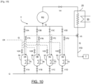
- the SC conditioning system includes a CQ fuel circuit (solid line on the [ Fig.2 ]) connected at the inlet to the cryogenic tank R1 and at the outlet to the turbine engine T.
- a flow of fuel Q circulates from upstream to downstream in the fuel circuit CQ in order to increase in pressure and temperature so that it can be injected into the combustion chamber of the turbine engine T without the risk of icing the fuel injectors.
- the fuel circuit CQ comprises a buffer tank R2 to supply the turbine engine T, in particular, to meet the variable needs of the turbine engine T.
- the buffer tank R2 ensures a continuous flow under pressure which is routed to the turbine engine T.
- upstream fuel circuit refers to the fuel circuit located upstream of the buffer tank R2
- downstream fuel circuit refers to the fuel circuit located downstream of the buffer tank. R2.
- the 2A-2D elementary heat sources come from the aircraft and/or the T turbine engine and can be of different types.
- the calories can come, for example, from the lubricating oil, the turbine of the T turbine engine, the cabin air, the electrical and electronic systems and/or an independent heating system integrated into the aircraft.
- the inlet valves V1A-V1D are used to control the flow rate of the fuel flow Q entering the elementary tanks 3A-3D.
- the outlet valves V3A-V3D are of the pressure reducer type and allow the fuel flow Q to be expanded after its isochoric compression in the buffer tank R2.
- the degassing valves V2A-V2D are also of the pressure reducer type and ensure the degassing of the elementary tanks 3A-3D to the cryogenic tank R1. Indeed, at the end of the expansion phase, an elementary tank 3A-3D must be degassed to reduce its pressure in order to be able to be refilled.
- the valves are controllable and connected to a control module (not shown) which allows their degree of opening and their activation to be controlled, in particular in a sequenced manner.
- the return circuit CR makes it possible to bring the gas flow G back into the cryogenic tank R1 to increase the gaseous headspace in the cryogenic tank R1, which leads to an increase in the pressure in the latter.
- the conditioning system SC comprises a discharge circuit CD which connects an upper part of the cryogenic tank R1 to a discharge member 12 making it possible to inject the gas flow G into the fuel circuit CQ upstream of the compression modules 1A-1D.
- the discharge circuit CD comprises a discharge valve V0 which is activated from a predetermined pressure threshold in the cryogenic tank R1 making it possible to evacuate a secondary flow comprising the gaseous fuel flow G.
- the discharge member 12 makes it possible to suck in a gaseous flow G when drawing off a main flow of fuel in the liquid phase from a lower part of the cryogenic tank R1.
- the discharge member 12 is in the form of a jet pump which makes it possible, by the Venturi effect, to convert the pressure energy of the liquid fuel flow Q (main flow) into kinetic energy to drive a gaseous fuel flow Q (secondary flow).
- a jet pump is also referred to as a Venturi effect pump.
- the jet pump has a nozzle of convergent-divergent shape (from upstream to downstream) so as to convert the pressure energy into kinetic energy and then inversely convert the kinetic energy into pressure energy.
- a jet pump does not have a mechanical drive and does not have the defects of a mechanical pump presented previously.
- the discharge member 12 could be in other forms, for example, a combination of an exchanger and a valve in order to liquefy the gas flow before its injection with the liquid fuel flow Q.
- the discharge member 12 is preferably passive and thus does not have a rotating member.
- the pressure increase of the fuel flow Q by isochoric compression is carried out in the compression modules 1A-1D connected in parallel so as to each achieve an independent pressure increase.
- four compression modules 1A-1D have been presented but it goes without saying that their number could be different depending on various factors such as the size of the elementary tanks 3A-3D, the power of the elementary heat sources 2A-2D, the filling time, the compression time, the expansion time and the degassing time.
- the buffer tank R2 is supplied by the elementary tanks 3A-3D and has a pressure lower than that reached in the tanks elementary 3A-3D at the end of the compression phase.
- the upstream fuel circuit further comprises a hydraulic booster pump 11, preferably immersed in the cryogenic tank R1, configured to take the fuel in the liquid phase and increase the pressure of the fuel flow Q by a few bars, in particular, from 1 to 3 bars.
- a hydraulic booster pump 11 i.e. a low-pressure pump, is less problematic than a high-pressure pump.
- the fuel circuit CQ comprises, between the hydraulic feed pump 11 and the discharge member 12, a first exchanger 21 and a second exchanger 22 which are mounted in series.
- the first exchanger 21 is configured to take calories from the gas flow G circulating in the return circuit CR and transmit them to the fuel flow Q.
- the gas flow X is thus cooled before being injected into the cryogenic tank R1 while the fuel flow Q gradually heats up.
- the second exchanger 22 is configured to take calories from a heat source 52 and transmit them to the fuel flow Q in order to control its temperature and its thermodynamic state (liquid, vapor, two-phase or supercritical) at the inlet of the elementary tanks 3A-3D of the compression modules 1A-1D.
- the second exchanger 22 makes it possible to gasify the fuel flow Q. The influence of the thermodynamic state will be presented later. In the case of a liquid supply at the inlet of the elementary tanks 3A-3D, the second exchanger 22 could be omitted.
- the fuel circuit CQ comprises, downstream of the buffer tank R2, a first regulating valve V4, a third exchanger 23 and a second regulating valve V5.
- the first control valve V4 is of the pressure reducer type, it ensures the stabilization of the pressure at the outlet of the buffer tank R2.
- the pressure downstream of the first control valve V4 is lower than that of the buffer tank R2, and corresponds to that required by the turbine engine T, which varies depending on the flight phase of the aircraft.
- the second control valve V5 is of the pressure reducer type and allows the fuel flow supplied to the turbine engine T to be controlled.
- the temperature of the fuel flow Q at the inlet of the buffer tank R2 is close to ambient temperature to avoid making its structure heavier by adding insulation.
- the third exchanger 23 for its part, allows the fuel flow Q to be heated from a third heat source 53 prior to its injection. This additional thermal energy allows the flow temperature to be precisely adjusted. of fuel Q. Thus, the fuel flow Q is injected at an optimal temperature.
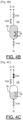
- the inlet valve V1A is open, the others being closed.
- the fuel flow Q enters the elementary tank 3A.
- the filling step is implemented at a pressure slightly lower than that of the liquid fuel at the outlet of the hydraulic booster pump 11, apart from the pressure losses.
- the elementary heat source 2A provides calories to the elementary tank 3A whose volume remains fixed, which increases the pressure of the fuel flow Q in the elementary tank 3A.
- the pressure at the end of compression can reach relatively high values, in particular, greater than 150 bars.
- outlet valve V3A is open, the others being closed.
- the fuel flow Q expands in the buffer tank R2.
- the pressure in the elementary tank 3A drops while that in the buffer tank R2 increases.
- the pressure in the buffer tank R2 can reach relatively high values, in particular, above 100 bar.
- the degassing valve V2A is open, the others being closed.
- the elementary tank 3A communicates fluidically with the cryogenic tank R1 via the return circuit CR to allow the circulation of the gas flow G.
- the pressure in the elementary tank 3A becomes equal to that of the cryogenic tank R1, of the order of 2 bars.
- the degassing valve V2A is closed and a new cycle can begin.
- each 1A-1D compression module allows a portion of the fuel flow Q to be pressurized to fill the buffer tank R2.
- the use of at least four 1A-1D compression modules in parallel is advantageous for exploiting this 4-stroke cycle.
- the 1A-1D compression modules are preferably out of phase to allow the buffer tank R2 to be continuously supplied.
- the first compression module 1A implements the filling step
- the second compression module 1B implements the isochoric compression step
- the third compression module 1C implements the expansion step
- the fourth compression module 1D implements the degassing step. It is nevertheless obvious that several compression modules 1A-1D could implement the same steps simultaneously.
- the hydraulic booster pump 11 successively supplies the exchangers 21, 22 then the discharge member 12 which makes it possible to inject the gas flow G, taken from the upper part of the cryogenic tank R1, with the fuel flow G taken from the lower part of the cryogenic tank R1.
- the fuel flow Q here enriched with a gas flow G, is introduced into the compression modules 1A-1D which increase the pressure of the fuel flow Q and fill the buffer tank R2.
- the gas flow G from the compression modules 1A-1D is reinjected into the cryogenic tank R1 via the first exchanger 21.
- a fuel flow G is taken from the buffer tank R2 and then preheated by the third exchanger 23 to its optimum temperature for injection.
- the presence of a buffer tank R2 ensures flexibility during operation.
- the 1A-1D compression modules can be supplied according to different thermodynamic states. Subsequently, P and T denote the pressure and temperature of the fuel flow Q at the inlet of the 1A-1D compression modules. Pc and Tc denote the critical pressure and critical temperature of the fuel considered.
- the supply can be carried out from a fuel flow Q in subcritical mode (P ⁇ Pc and T ⁇ Tc) in the liquid state (vapor content ⁇ 1), two-phase (0 ⁇ vapor content ⁇ 1) or vapor (vapor content >1).
- the hydraulic booster pump 11 is sufficient to convey the fuel flow Q (initially in the subcritical liquid state) from the main tank R1 to the elementary tanks 3A-3D.
- the supply can be carried out from a fuel flow Q in compressed liquid (P > Pc and T ⁇ Tc), or in supercritical (P > Pc and T > Tc).
- a mechanical booster pump 20 is interposed between the hydraulic booster pump 11 and the first exchanger 21, in order to compress the fuel flow Q to a pressure higher than the critical pressure.
- the mechanical booster pump 20 only provides part of the compression, of the order of a few bars to exceed the critical pressure (around 13 bars for hydrogen for example), the additional pressure increase is advantageously provided by the isochoric compression of the compression modules 1A-1D.
- the feed can be made from a fuel flow Q in superheated gas (P ⁇ Pc and T > Tc).
- the hydraulic booster pump 11 is sufficient to convey the fuel flow Q (initially in the subcritical liquid state) from the main tank R1 to the elementary tanks 3A-3D.
- each 1A-1D compression module may comprise at least two elementary tanks connected in series.
- a series arrangement allows for multi-stage compression, with each of the elementary tanks corresponding to a compression stage.
- Such a configuration allows for the use of smaller elementary tanks to form a more compact SC conditioning system.
- the fuel flow Q is pressurized in a first elementary tank 3A-3D then pressurized in a second elementary tank 3A'-3D'.
- the second exchanger 22 draws calories from the fuel circuit CQ downstream of the buffer tank R2 (in the downstream fuel circuit) in order to heat the fuel flow Q leaving the cryogenic tank R1.
- a hot fuel flow Q as a heat source instead of a hot air flow makes it possible to avoid condensation and/or icing in the second exchanger 22.
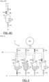
- the conditioning system SC comprises an injection circuit CI connecting the cryogenic tank R1, the tank buffer R2 and the return circuit CR.
- the injection circuit CI comprises in this example two compression modules 1A', 1B' of a structure similar to previously to supply the buffer tank R2 directly with the gas flow G from the cryogenic tank R1.
- Each compression module 1A', 1B' allows the admission of a gas flow G from the cryogenic tank R1 into an elementary tank in order to be pressurized to supply the buffer tank R2.
- the gas flow G from the degassing of the compression modules 1A', 1B' is introduced into the return circuit CR in order to be cooled by the first exchanger 21 before being reintroduced into the cryogenic tank R1.
- the supply of the buffer tank R2 can thus be carried out by the liquid phase and the gaseous phase of the fuel from the cryogenic tank R1.
- Such an injection circuit CI is advantageous when a discharge member 12 is not capable of eliminating all of the gas overpressure by Venturi effect.
- each compression module 1A-1D has a supply valve V7A-V7D which takes a fuel flow at the second control valve V5 which is a three-way valve in this variant.
- V7A-V7D takes a fuel flow at the second control valve V5 which is a three-way valve in this variant.
- the isochoric compression step initially, all the valves are closed except for the supply valve V7A-V7D so that the pressure in the buffer tank R2 equalizes with that of the elementary tank 3A-3D.
- the supply valve V7A-V7D allows an initial pressurization.
- all the valves are closed and the elementary heat source 2A-2D supplies calories to the elementary tank 3A-3D whose volume remains fixed, which increases the pressure of the fuel flow Q in the elementary tank 3A-3D. In other words, a second pressurization is carried out by heat input.
- Such a variant is particularly advantageous when the elementary sources 2A-2D are not capable on their own of ensuring all the pressure increase in the elementary tanks 3A-3D, for example, when the elementary tanks 3A-3D are positioned far from the elementary sources 2A-2D and the third exchanger 23 is close to the turbine engine T and has a significant heat source making it possible to provide thermal energy to the fuel flow Q in an optimal manner.
Landscapes
- Engineering & Computer Science (AREA)
- Chemical & Material Sciences (AREA)
- Combustion & Propulsion (AREA)
- Mechanical Engineering (AREA)
- General Engineering & Computer Science (AREA)
- Aviation & Aerospace Engineering (AREA)
- Filling Or Discharging Of Gas Storage Vessels (AREA)
Claims (15)
- Kraftstoffkonditionierungssystem (SC), das ausgelegt ist, um ein Flugzeugturbotriebwerk (T) mit Kraftstoff (Q) aus einem Kryotank (R1) zu versorgen, wobei das Konditionierungssystem (SC) einen Kraftstoffkreis (CQ) umfasst, der am Eingang mit dem Kryotank (R1) und am Ausgang mit dem Turbotriebwerk (T) verbunden ist, wobei ein Kraftstoffstrom (Q) in dem Kraftstoffkreis (CQ) von stromaufwärts nach stromabwärts zirkuliert, wobei das System dadurch gekennzeichnet ist, dass der Kraftstoffkreis (CQ) einen Puffertank (R2) zur Versorgung des Turbinentriebwerks (T) und eine Vielzahl von Kompressionsmodulen (1A-1D) umfasst, die zur Versorgung des Puffertanks (R2) ausgelegt sind, wobei jedes Kompressionsmodul (1A-1D) umfasst:• einen elementaren Tank (3A-3D) mit festem Volumen,• eine elementare Wärmequelle (2A-2D), die ausgelegt ist, um die Temperatur des Kraftstoffs in dem elementaren Tank (3A-3D) isochor zu erhöhen,• ein Einlassventil (V1A-V1D), das den elementaren Tank (3A-3D) mit einem stromaufwärts gelegenen Teil des Kraftstoffkreises (CQ) verbindet,• ein Auslassventil (V3A-V3D), das den elementaren Tank (3A-3D) mit dem Puffertank (R2) verbindet, und• ein Entgasungsventil (V2A-V2D), das den elementaren Tank (3A-3D) mit dem Kryotank (R1) über einen Rückführungskreis (CR) verbindet, in dem ein Gasstrom (G) zirkuliert.
- Konditionierungssystem (SC) nach Anspruch 1, wobei die Kompressionsmodule (1A-1D) parallel angebracht sind.
- Konditionierungssystem (SC) nach einem der Ansprüche 1 bis 2, wobei jede elementare Wärmequelle (2A-2D) Kalorien aus dem Turbotriebwerk (T) und/oder dem Flugzeug bereitstellt.
- Konditionierungssystem (SC) nach einem der Ansprüche 1 bis 3, wobei mindestens ein Kompressionsmodul (1A-1D) mindestens zwei in Reihe angebrachte elementare Tanks (3A-3D, 3A'-3D') umfasst.
- Konditionierungssystem (SC) nach einem der Ansprüche 1 bis 4, wobei mindestens ein Kompressionsmodul (1A-1D) ein Zufuhrventil (V7A-V7D) umfasst, das ausgelegt ist, um den Druck in dem elementaren Tank (3A-3D) durch In-Kommunikation-Versetzen des elementaren Tanks (3A-3D) mit dem Puffertankt (R2) zu erhöhen.
- Konditionierungssystem (SC) nach einem der Ansprüche 1 bis 5, umfassend mindestens einen ersten Wärmetauscher (21), der ausgelegt ist, um dem im Rückführungskreis (CR) zirkulierenden Gasstrom (G) Kalorien zu entnehmen und diese an den Kraftstoffstrom (Q) zu übertragen.
- Konditionierungssystem (SC) nach einem der Ansprüche 1 bis 6, umfassend mindestens einen zweiten Wärmetauscher (22) stromaufwärts der Kompressionsmodule (1A-1D), der ausgelegt ist, um einer Wärmequelle (52) Kalorien zu entnehmen und diese an den Kraftstoffstrom (Q) zu übertragen.
- Konditionierungssystem (SC) nach einem der Ansprüche 1 bis 7, umfassend mindestens einen dritten Wärmetauscher (23) stromabwärts der Kompressionsmodule (1A-1D), der ausgelegt ist, um einer Wärmequelle (53) Kalorien zu entnehmen und diese an den Kraftstoffstrom (Q) vor dessen Einspritzung in das Turbotriebwerk (T) zu übertragen.
- Klimatisierungssystem (SC) nach einem der Ansprüche 1 bis 8, umfassend mindestens eine mechanischen Zusatzpumpe (20), die stromaufwärts der Kompressionsmodule (1A-1D) angebracht ist.
- Konditionierungssystem (SC) nach einem der Ansprüche 1 bis 9, umfassend einen Entlastungskreis (CD) für einen Gasstrom (G) aus dem Kryotank (R1) und ein Entlastungsorgan (12), das stromaufwärts der Kompressionsmodule (1A-1D) positioniert und ausgelegt ist, um den Kraftstoffstrom (Q) mit Gasstrom (G) anzureichern.
- Konditionierungssystem (SC) nach einem der Ansprüche 1 bis 10, umfassend einem Injektionskreis (CI) für einen Gasstrom (G) aus dem Kryotank (R1) in den Puffertank (R2), wobei der Injektionskreis (CI) mindestens ein isochores Kompressionsmodul (1A'-1B') umfasst.
- Anordnung aus mindestens einem Kryotank (R1), einem Flugzeugturbotriebwerk (T) und einem Konditionierungssystem (SC) nach einem der vorhergehenden Ansprüche, die den Kryotank (R1) und das Flugzeugturbotriebwerk (T) fluidisch miteinander verbindet.
- Konditionierungsverfahren (SC) mit Kraftstoff eines Flugzeugtriebwerks (T) mittels Kraftstoffs (Q) aus einem Kryotank (R1) mit Hilfe eines Konditionierungssystems (SC) nach einem der Ansprüche 1 bis 11, wobei bei dem Verfahren:• die Kompressionsmodule (1A-1D) eine isochore Kompression des Kraftstoffstroms (Q) aus dem Kryotank (R1) durchführen, um den Puffertank (R2) zu versorgen, und• der Puffertank (R2) das Turbotriebwerk (T) mit einem Kraftstoffstrom (Q) versorgt.
- Konditionierungsverfahren (SC) nach Anspruch 13, wobei mindestens zwei Kompressionsmodule (1A-1D) phasenverschoben gesteuert werden.
- Konditionierungsverfahren (SC) mit Kraftstoff nach einem der Ansprüche 13 bis 14, wobei das Verfahren für jedes Kompressionsmodul (1A-1D) die Schritte Füllen, isochore Kompression, Entspannung und Entgasung umfasst.
Applications Claiming Priority (2)
| Application Number | Priority Date | Filing Date | Title |
|---|---|---|---|
| FR2106216A FR3123890B1 (fr) | 2021-06-14 | 2021-06-14 | Système et procédé de conditionnement de carburant configuré pour alimenter un turbomoteur d’aéronef à partir de carburant issu d’un réservoir cryogénique |
| PCT/EP2022/065799 WO2022263307A1 (fr) | 2021-06-14 | 2022-06-10 | Système et procédé de conditionnement de carburant configuré pour alimenter un turbomoteur d'aéronef à partir de carburant issu d'un réservoir cryogénique |
Publications (2)
| Publication Number | Publication Date |
|---|---|
| EP4355986A1 EP4355986A1 (de) | 2024-04-24 |
| EP4355986B1 true EP4355986B1 (de) | 2025-04-09 |
Family
ID=78827625
Family Applications (1)
| Application Number | Title | Priority Date | Filing Date |
|---|---|---|---|
| EP22732256.7A Active EP4355986B1 (de) | 2021-06-14 | 2022-06-10 | Brennstoffkonditionierungssystem und verfahren zur versorgung eines flugzeugturbinenmotors mit brennstoff aus einem kryotank |
Country Status (5)
| Country | Link |
|---|---|
| US (1) | US12162621B2 (de) |
| EP (1) | EP4355986B1 (de) |
| CN (1) | CN117480315A (de) |
| FR (1) | FR3123890B1 (de) |
| WO (1) | WO2022263307A1 (de) |
Cited By (1)
| Publication number | Priority date | Publication date | Assignee | Title |
|---|---|---|---|---|
| US20260022664A1 (en) * | 2024-07-18 | 2026-01-22 | General Electric Company | Fuel thermal management systems and related methods |
Families Citing this family (14)
| Publication number | Priority date | Publication date | Assignee | Title |
|---|---|---|---|---|
| FR3143558A1 (fr) * | 2022-12-20 | 2024-06-21 | Airbus Operations | Installation de réchauffement pour un aéronef comportant un réservoir de dihydrogène, un moteur et des systèmes de réchauffement du dihydrogène |
| US12330801B2 (en) | 2023-05-30 | 2025-06-17 | Rtx Corporation | Cooling architecture for liquid hydrogen superconducting system |
| FR3151574A1 (fr) * | 2023-07-28 | 2025-01-31 | Safran | Système et procédé de génération d’une puissance électrique pour un aéronef à partir d’une pile à combustible |
| FR3153127B1 (fr) | 2023-09-14 | 2026-03-06 | Aresia Villeneuve | Dispositif de reservoir tampon biphasique haute pression |
| FR3153332B1 (fr) | 2023-09-22 | 2025-08-15 | Safran | Système de conditionnement de carburant pour alimenter un système de propulsion d’aéronef à partir de carburant issu d’un réservoir cryogénique et procédé associé |
| GB202316850D0 (en) * | 2023-11-03 | 2023-12-20 | Rolls Royce Plc | Gas turbine engine |
| GB202400631D0 (en) * | 2024-01-17 | 2024-02-28 | Rolls Royce Plc | Hydrogen fuelled gas turbine engine |
| EP4606709A1 (de) * | 2024-02-23 | 2025-08-27 | GE Avio S.r.l. | Mehrphasige flüssigkraftstoffsysteme und zugehörige verfahren |
| US20250290635A1 (en) * | 2024-03-12 | 2025-09-18 | Rtx Corporation | Liquid hydrogen fuel system with thermal compression |
| FR3162208A1 (fr) * | 2024-05-16 | 2025-11-21 | Safran Aircraft Engines | Dispositif amélioré d’alimentation en fluide cryogénique pour turboréacteur aéronautique |
| FR3162209A1 (fr) * | 2024-05-16 | 2025-11-21 | Safran Aircraft Engines | Dispositif amélioré d’alimentation en fluide cryogénique pour turboréacteur aéronautique |
| FR3164269A1 (fr) * | 2024-07-03 | 2026-01-09 | Airbus Operations | Dispositif d’alimentation en carburant comprenant au moins deux réservoirs d’hydrogène à l’état liquide et à des pressions différentes |
| FR3164250A1 (fr) | 2024-07-04 | 2026-01-09 | Safran | Dispositif aéronautique de distribution de gaz |
| CN119934411B (zh) * | 2025-01-22 | 2025-10-17 | 中国科学院理化技术研究所 | 一种适用于混合氢动力飞机的液氢燃料储供系统 |
Family Cites Families (12)
| Publication number | Priority date | Publication date | Assignee | Title |
|---|---|---|---|---|
| FR2904054B1 (fr) * | 2006-07-21 | 2013-04-19 | Guy Joseph Jules Negre | Moteur cryogenique a energie thermique ambiante et pression constante et ses cycles thermodynamiques |
| AU2007335250B2 (en) * | 2006-12-21 | 2014-01-23 | Mosaic Technology Development Pty Ltd | A compressed gas transfer system |
| DE102011104546B4 (de) * | 2011-06-18 | 2013-05-29 | Magna Steyr Fahrzeugtechnik Ag & Co. Kg | Pumpe zum Fördern eines kryogenen Fluids |
| EP2938541A1 (de) * | 2012-12-28 | 2015-11-04 | General Electric Company | Flugzeug und system zur nachrüstung eines kryokraftstoffs |
| EP3030827A4 (de) * | 2013-08-09 | 2017-07-19 | Mosaic Technology Development Pty Ltd | System und verfahren zur ausgeglichenen betankung einer vielzahl von druckgas-druckbehälter |
| KR102286702B1 (ko) * | 2017-09-08 | 2021-08-09 | 한국조선해양 주식회사 | 가스 처리 시스템 및 이를 포함하는 선박 |
| FR3074255B1 (fr) * | 2017-11-24 | 2021-06-04 | Engie | Dispositif et procede autonome de fourniture d'electricite |
| US10989117B2 (en) * | 2018-09-14 | 2021-04-27 | Raytheon Technologies Corporation | Hybrid expander cycle with pre-compression cooling and turbo-generator |
| DE102018221323A1 (de) * | 2018-12-10 | 2020-06-10 | Robert Bosch Gmbh | Kraftstofffördereinrichtung für eine Brennkraftmaschine |
| FR3097948B1 (fr) * | 2019-06-26 | 2021-06-25 | Lair Liquide Sa Pour Letude Et L’Exploitation Des Procedes Georges Claude | Refroidisseur cryogénique pour détecteur de rayonnement notamment dans un engin spatial |
| FR3110937B1 (fr) * | 2020-05-28 | 2022-04-29 | Safran | Installation d’alimentation en carburant cryogénique de la chambre de combustion d’une turbomachine. |
| CH717460A1 (de) * | 2020-05-28 | 2021-11-30 | Liebherr Machines Bulle Sa | System zum Bereitstellen eines gasförmigen Kraftstoffs. |
-
2021
- 2021-06-14 FR FR2106216A patent/FR3123890B1/fr active Active
-
2022
- 2022-06-10 CN CN202280040683.6A patent/CN117480315A/zh active Pending
- 2022-06-10 EP EP22732256.7A patent/EP4355986B1/de active Active
- 2022-06-10 US US18/567,408 patent/US12162621B2/en active Active
- 2022-06-10 WO PCT/EP2022/065799 patent/WO2022263307A1/fr not_active Ceased
Cited By (1)
| Publication number | Priority date | Publication date | Assignee | Title |
|---|---|---|---|---|
| US20260022664A1 (en) * | 2024-07-18 | 2026-01-22 | General Electric Company | Fuel thermal management systems and related methods |
Also Published As
| Publication number | Publication date |
|---|---|
| FR3123890A1 (fr) | 2022-12-16 |
| US20240270402A1 (en) | 2024-08-15 |
| US12162621B2 (en) | 2024-12-10 |
| FR3123890B1 (fr) | 2023-05-12 |
| EP4355986A1 (de) | 2024-04-24 |
| WO2022263307A1 (fr) | 2022-12-22 |
| CN117480315A (zh) | 2024-01-30 |
Similar Documents
| Publication | Publication Date | Title |
|---|---|---|
| EP4355986B1 (de) | Brennstoffkonditionierungssystem und verfahren zur versorgung eines flugzeugturbinenmotors mit brennstoff aus einem kryotank | |
| EP4158169B1 (de) | Anlage zum erwärmen eines kryogenen kraftstoffs | |
| EP3044527B1 (de) | Vorrichtung zur rückgewinnung von dämpfen aus einem kryotank | |
| EP4305287B1 (de) | Brennstoffkonditionierungssystem und verfahren zur versorgung eines flugzeugturbinenmotors mit brennstoff aus einem kryotank | |
| EP4189224A1 (de) | Kreislauf zur zuführung von kraftstoff zu einer luftfahrt-kryoturbomaschine und zugehöriges verfahren | |
| WO2013088030A1 (fr) | Dispositif et procede de pressurisation | |
| FR3040773A1 (fr) | Systeme et procede de traitement de gaz issu de l'evaporation d'un liquide cryogenique | |
| WO2023072623A1 (fr) | Système de conditionnement de carburant pour alimenter une turbomachine d'aéronef, procédé d'alimentation d'une turbomachine | |
| WO2023072614A1 (fr) | Système de conditionnement de carburant pour alimenter une turbomachine d'aéronef, aéronef et procédé d'utilisation | |
| EP4381182B1 (de) | System zur aufbereitung von kraftstoff zur versorgung einer flugzeugturbomaschine und verfahren zur versorgung einer flugzeugturbomaschine mit kraftstoff | |
| EP2864620A1 (de) | Turbopumpe | |
| EP4453404B1 (de) | System und verfahren zur konditionierung von kraftstoff für einen luftatmenden wasserstoffmotor | |
| FR3153332A1 (fr) | Système de conditionnement de carburant pour alimenter un système de propulsion d’aéronef à partir de carburant issu d’un réservoir cryogénique et procédé associé | |
| FR3123889A1 (fr) | Système et procédé de conditionnement de carburant configuré pour alimenter un turbomoteur d’aéronef à partir de carburant issu d’un réservoir cryogénique | |
| EP4515090B1 (de) | System zur steuerung der temperatur einer wärmeübertragungsflüssigkeit in einem kreislauf und temperatursteuerungsverfahren | |
| EP4674760A1 (de) | Kraftstoffversorgungseinrichtung mit mindestens zwei wasserstofftanks im flüssigen zustand und unterschiedlichen drücken | |
| FR3133404A1 (fr) | Système de suralimentation en air pour système de conditionnement de carburant et procédé d’utilisation | |
| WO2024078930A1 (fr) | Système de conditionnement de carburant pour alimenter une turbomachine d'aéronef, procédé d'alimentation d'une turbomachine | |
| FR3162207A1 (fr) | Système de conditionnement de carburant pour aéronef comprenant un circuit de purge, procédé de purge associé | |
| FR3160446A1 (fr) | Système de compression thermique d’un fluide cryogénique liquéfié, station de distribution et procédé utilisant un tel système de compression thermique. |
Legal Events
| Date | Code | Title | Description |
|---|---|---|---|
| STAA | Information on the status of an ep patent application or granted ep patent |
Free format text: STATUS: UNKNOWN |
|
| STAA | Information on the status of an ep patent application or granted ep patent |
Free format text: STATUS: THE INTERNATIONAL PUBLICATION HAS BEEN MADE |
|
| PUAI | Public reference made under article 153(3) epc to a published international application that has entered the european phase |
Free format text: ORIGINAL CODE: 0009012 |
|
| STAA | Information on the status of an ep patent application or granted ep patent |
Free format text: STATUS: REQUEST FOR EXAMINATION WAS MADE |
|
| 17P | Request for examination filed |
Effective date: 20231128 |
|
| AK | Designated contracting states |
Kind code of ref document: A1 Designated state(s): AL AT BE BG CH CY CZ DE DK EE ES FI FR GB GR HR HU IE IS IT LI LT LU LV MC MK MT NL NO PL PT RO RS SE SI SK SM TR |
|
| DAV | Request for validation of the european patent (deleted) | ||
| DAX | Request for extension of the european patent (deleted) | ||
| GRAP | Despatch of communication of intention to grant a patent |
Free format text: ORIGINAL CODE: EPIDOSNIGR1 |
|
| STAA | Information on the status of an ep patent application or granted ep patent |
Free format text: STATUS: GRANT OF PATENT IS INTENDED |
|
| INTG | Intention to grant announced |
Effective date: 20250117 |
|
| GRAS | Grant fee paid |
Free format text: ORIGINAL CODE: EPIDOSNIGR3 |
|
| GRAA | (expected) grant |
Free format text: ORIGINAL CODE: 0009210 |
|
| STAA | Information on the status of an ep patent application or granted ep patent |
Free format text: STATUS: THE PATENT HAS BEEN GRANTED |
|
| AK | Designated contracting states |
Kind code of ref document: B1 Designated state(s): AL AT BE BG CH CY CZ DE DK EE ES FI FR GB GR HR HU IE IS IT LI LT LU LV MC MK MT NL NO PL PT RO RS SE SI SK SM TR |
|
| REG | Reference to a national code |
Ref country code: GB Ref legal event code: FG4D Free format text: NOT ENGLISH |
|
| REG | Reference to a national code |
Ref country code: CH Ref legal event code: EP |
|
| REG | Reference to a national code |
Ref country code: DE Ref legal event code: R096 Ref document number: 602022012984 Country of ref document: DE |
|
| REG | Reference to a national code |
Ref country code: IE Ref legal event code: FG4D Free format text: LANGUAGE OF EP DOCUMENT: FRENCH |
|
| PGFP | Annual fee paid to national office [announced via postgrant information from national office to epo] |
Ref country code: DE Payment date: 20250618 Year of fee payment: 4 |
|
| PGFP | Annual fee paid to national office [announced via postgrant information from national office to epo] |
Ref country code: FR Payment date: 20250623 Year of fee payment: 4 |
|
| PGFP | Annual fee paid to national office [announced via postgrant information from national office to epo] |
Ref country code: AT Payment date: 20250721 Year of fee payment: 4 |
|
| REG | Reference to a national code |
Ref country code: NL Ref legal event code: MP Effective date: 20250409 |
|
| PG25 | Lapsed in a contracting state [announced via postgrant information from national office to epo] |
Ref country code: NL Free format text: LAPSE BECAUSE OF FAILURE TO SUBMIT A TRANSLATION OF THE DESCRIPTION OR TO PAY THE FEE WITHIN THE PRESCRIBED TIME-LIMIT Effective date: 20250409 |
|
| REG | Reference to a national code |
Ref country code: AT Ref legal event code: MK05 Ref document number: 1783688 Country of ref document: AT Kind code of ref document: T Effective date: 20250409 |
|
| PG25 | Lapsed in a contracting state [announced via postgrant information from national office to epo] |
Ref country code: PT Free format text: LAPSE BECAUSE OF FAILURE TO SUBMIT A TRANSLATION OF THE DESCRIPTION OR TO PAY THE FEE WITHIN THE PRESCRIBED TIME-LIMIT Effective date: 20250811 Ref country code: FI Free format text: LAPSE BECAUSE OF FAILURE TO SUBMIT A TRANSLATION OF THE DESCRIPTION OR TO PAY THE FEE WITHIN THE PRESCRIBED TIME-LIMIT Effective date: 20250409 Ref country code: ES Free format text: LAPSE BECAUSE OF FAILURE TO SUBMIT A TRANSLATION OF THE DESCRIPTION OR TO PAY THE FEE WITHIN THE PRESCRIBED TIME-LIMIT Effective date: 20250409 |
|
| REG | Reference to a national code |
Ref country code: LT Ref legal event code: MG9D |
|
| PG25 | Lapsed in a contracting state [announced via postgrant information from national office to epo] |
Ref country code: NO Free format text: LAPSE BECAUSE OF FAILURE TO SUBMIT A TRANSLATION OF THE DESCRIPTION OR TO PAY THE FEE WITHIN THE PRESCRIBED TIME-LIMIT Effective date: 20250709 Ref country code: GR Free format text: LAPSE BECAUSE OF FAILURE TO SUBMIT A TRANSLATION OF THE DESCRIPTION OR TO PAY THE FEE WITHIN THE PRESCRIBED TIME-LIMIT Effective date: 20250710 |
|
| PG25 | Lapsed in a contracting state [announced via postgrant information from national office to epo] |
Ref country code: PL Free format text: LAPSE BECAUSE OF FAILURE TO SUBMIT A TRANSLATION OF THE DESCRIPTION OR TO PAY THE FEE WITHIN THE PRESCRIBED TIME-LIMIT Effective date: 20250409 |
|
| PG25 | Lapsed in a contracting state [announced via postgrant information from national office to epo] |
Ref country code: BG Free format text: LAPSE BECAUSE OF FAILURE TO SUBMIT A TRANSLATION OF THE DESCRIPTION OR TO PAY THE FEE WITHIN THE PRESCRIBED TIME-LIMIT Effective date: 20250409 |
|
| PG25 | Lapsed in a contracting state [announced via postgrant information from national office to epo] |
Ref country code: AT Free format text: LAPSE BECAUSE OF FAILURE TO SUBMIT A TRANSLATION OF THE DESCRIPTION OR TO PAY THE FEE WITHIN THE PRESCRIBED TIME-LIMIT Effective date: 20250409 Ref country code: HR Free format text: LAPSE BECAUSE OF FAILURE TO SUBMIT A TRANSLATION OF THE DESCRIPTION OR TO PAY THE FEE WITHIN THE PRESCRIBED TIME-LIMIT Effective date: 20250409 |
|
| PG25 | Lapsed in a contracting state [announced via postgrant information from national office to epo] |
Ref country code: RS Free format text: LAPSE BECAUSE OF FAILURE TO SUBMIT A TRANSLATION OF THE DESCRIPTION OR TO PAY THE FEE WITHIN THE PRESCRIBED TIME-LIMIT Effective date: 20250709 |
|
| PG25 | Lapsed in a contracting state [announced via postgrant information from national office to epo] |
Ref country code: IS Free format text: LAPSE BECAUSE OF FAILURE TO SUBMIT A TRANSLATION OF THE DESCRIPTION OR TO PAY THE FEE WITHIN THE PRESCRIBED TIME-LIMIT Effective date: 20250809 |
|
| PG25 | Lapsed in a contracting state [announced via postgrant information from national office to epo] |
Ref country code: LV Free format text: LAPSE BECAUSE OF FAILURE TO SUBMIT A TRANSLATION OF THE DESCRIPTION OR TO PAY THE FEE WITHIN THE PRESCRIBED TIME-LIMIT Effective date: 20250409 |
|
| REG | Reference to a national code |
Ref country code: DE Ref legal event code: R097 Ref document number: 602022012984 Country of ref document: DE |
|
| PG25 | Lapsed in a contracting state [announced via postgrant information from national office to epo] |
Ref country code: SM Free format text: LAPSE BECAUSE OF FAILURE TO SUBMIT A TRANSLATION OF THE DESCRIPTION OR TO PAY THE FEE WITHIN THE PRESCRIBED TIME-LIMIT Effective date: 20250409 Ref country code: DK Free format text: LAPSE BECAUSE OF FAILURE TO SUBMIT A TRANSLATION OF THE DESCRIPTION OR TO PAY THE FEE WITHIN THE PRESCRIBED TIME-LIMIT Effective date: 20250409 |
|
| PG25 | Lapsed in a contracting state [announced via postgrant information from national office to epo] |
Ref country code: CZ Free format text: LAPSE BECAUSE OF FAILURE TO SUBMIT A TRANSLATION OF THE DESCRIPTION OR TO PAY THE FEE WITHIN THE PRESCRIBED TIME-LIMIT Effective date: 20250409 |
|
| PG25 | Lapsed in a contracting state [announced via postgrant information from national office to epo] |
Ref country code: EE Free format text: LAPSE BECAUSE OF FAILURE TO SUBMIT A TRANSLATION OF THE DESCRIPTION OR TO PAY THE FEE WITHIN THE PRESCRIBED TIME-LIMIT Effective date: 20250409 |
|
| PG25 | Lapsed in a contracting state [announced via postgrant information from national office to epo] |
Ref country code: SK Free format text: LAPSE BECAUSE OF FAILURE TO SUBMIT A TRANSLATION OF THE DESCRIPTION OR TO PAY THE FEE WITHIN THE PRESCRIBED TIME-LIMIT Effective date: 20250409 |
|
| REG | Reference to a national code |
Ref country code: CH Ref legal event code: H13 Free format text: ST27 STATUS EVENT CODE: U-0-0-H10-H13 (AS PROVIDED BY THE NATIONAL OFFICE) Effective date: 20260127 |
|
| PG25 | Lapsed in a contracting state [announced via postgrant information from national office to epo] |
Ref country code: IT Free format text: LAPSE BECAUSE OF FAILURE TO SUBMIT A TRANSLATION OF THE DESCRIPTION OR TO PAY THE FEE WITHIN THE PRESCRIBED TIME-LIMIT Effective date: 20250409 |
|
| PG25 | Lapsed in a contracting state [announced via postgrant information from national office to epo] |
Ref country code: MC Free format text: LAPSE BECAUSE OF FAILURE TO SUBMIT A TRANSLATION OF THE DESCRIPTION OR TO PAY THE FEE WITHIN THE PRESCRIBED TIME-LIMIT Effective date: 20250409 |
|
| PLBE | No opposition filed within time limit |
Free format text: ORIGINAL CODE: 0009261 |
|
| STAA | Information on the status of an ep patent application or granted ep patent |
Free format text: STATUS: NO OPPOSITION FILED WITHIN TIME LIMIT |
|
| PG25 | Lapsed in a contracting state [announced via postgrant information from national office to epo] |
Ref country code: LU Free format text: LAPSE BECAUSE OF NON-PAYMENT OF DUE FEES Effective date: 20250610 |
|
| REG | Reference to a national code |
Ref country code: CH Ref legal event code: L10 Free format text: ST27 STATUS EVENT CODE: U-0-0-L10-L00 (AS PROVIDED BY THE NATIONAL OFFICE) Effective date: 20260218 |
|
| REG | Reference to a national code |
Ref country code: BE Ref legal event code: MM Effective date: 20250630 |
|
| PG25 | Lapsed in a contracting state [announced via postgrant information from national office to epo] |
Ref country code: RO Free format text: LAPSE BECAUSE OF FAILURE TO SUBMIT A TRANSLATION OF THE DESCRIPTION OR TO PAY THE FEE WITHIN THE PRESCRIBED TIME-LIMIT Effective date: 20250409 |
|
| 26N | No opposition filed |
Effective date: 20260112 |