EP4355682B1 - Steuerkonsole für eine personenhebemaschine und personenhebemaschine mit solch einer steuerkonsole - Google Patents
Steuerkonsole für eine personenhebemaschine und personenhebemaschine mit solch einer steuerkonsole Download PDFInfo
- Publication number
- EP4355682B1 EP4355682B1 EP22732588.3A EP22732588A EP4355682B1 EP 4355682 B1 EP4355682 B1 EP 4355682B1 EP 22732588 A EP22732588 A EP 22732588A EP 4355682 B1 EP4355682 B1 EP 4355682B1
- Authority
- EP
- European Patent Office
- Prior art keywords
- control console
- joystick
- flat surface
- platform
- main body
- Prior art date
- Legal status (The legal status is an assumption and is not a legal conclusion. Google has not performed a legal analysis and makes no representation as to the accuracy of the status listed.)
- Active
Links
Images


Classifications
-
- G—PHYSICS
- G05—CONTROLLING; REGULATING
- G05G—CONTROL DEVICES OR SYSTEMS INSOFAR AS CHARACTERISED BY MECHANICAL FEATURES ONLY
- G05G9/00—Manually-actuated control mechanisms provided with one single controlling member co-operating with two or more controlled members, e.g. selectively, simultaneously
- G05G9/02—Manually-actuated control mechanisms provided with one single controlling member co-operating with two or more controlled members, e.g. selectively, simultaneously the controlling member being movable in different independent ways, movement in each individual way actuating one controlled member only
- G05G9/04—Manually-actuated control mechanisms provided with one single controlling member co-operating with two or more controlled members, e.g. selectively, simultaneously the controlling member being movable in different independent ways, movement in each individual way actuating one controlled member only in which movement in two or more ways can occur simultaneously
- G05G9/047—Manually-actuated control mechanisms provided with one single controlling member co-operating with two or more controlled members, e.g. selectively, simultaneously the controlling member being movable in different independent ways, movement in each individual way actuating one controlled member only in which movement in two or more ways can occur simultaneously the controlling member being movable by hand about orthogonal axes, e.g. joysticks
-
- B—PERFORMING OPERATIONS; TRANSPORTING
- B66—HOISTING; LIFTING; HAULING
- B66F—HOISTING, LIFTING, HAULING OR PUSHING, NOT OTHERWISE PROVIDED FOR, e.g. DEVICES WHICH APPLY A LIFTING OR PUSHING FORCE DIRECTLY TO THE SURFACE OF A LOAD
- B66F11/00—Lifting devices specially adapted for particular uses not otherwise provided for
- B66F11/04—Lifting devices specially adapted for particular uses not otherwise provided for for movable platforms or cabins, e.g. on vehicles, permitting workmen to place themselves in any desired position for carrying out required operations
- B66F11/044—Working platforms suspended from booms
-
- B—PERFORMING OPERATIONS; TRANSPORTING
- B66—HOISTING; LIFTING; HAULING
- B66F—HOISTING, LIFTING, HAULING OR PUSHING, NOT OTHERWISE PROVIDED FOR, e.g. DEVICES WHICH APPLY A LIFTING OR PUSHING FORCE DIRECTLY TO THE SURFACE OF A LOAD
- B66F9/00—Devices for lifting or lowering bulky or heavy goods for loading or unloading purposes
- B66F9/06—Devices for lifting or lowering bulky or heavy goods for loading or unloading purposes movable, with their loads, on wheels or the like, e.g. fork-lift trucks
- B66F9/075—Constructional features or details
- B66F9/0759—Details of operating station, e.g. seats, levers, operator platforms, cabin suspension
-
- G—PHYSICS
- G05—CONTROLLING; REGULATING
- G05G—CONTROL DEVICES OR SYSTEMS INSOFAR AS CHARACTERISED BY MECHANICAL FEATURES ONLY
- G05G9/00—Manually-actuated control mechanisms provided with one single controlling member co-operating with two or more controlled members, e.g. selectively, simultaneously
- G05G9/02—Manually-actuated control mechanisms provided with one single controlling member co-operating with two or more controlled members, e.g. selectively, simultaneously the controlling member being movable in different independent ways, movement in each individual way actuating one controlled member only
- G05G9/04—Manually-actuated control mechanisms provided with one single controlling member co-operating with two or more controlled members, e.g. selectively, simultaneously the controlling member being movable in different independent ways, movement in each individual way actuating one controlled member only in which movement in two or more ways can occur simultaneously
- G05G9/047—Manually-actuated control mechanisms provided with one single controlling member co-operating with two or more controlled members, e.g. selectively, simultaneously the controlling member being movable in different independent ways, movement in each individual way actuating one controlled member only in which movement in two or more ways can occur simultaneously the controlling member being movable by hand about orthogonal axes, e.g. joysticks
- G05G2009/04774—Manually-actuated control mechanisms provided with one single controlling member co-operating with two or more controlled members, e.g. selectively, simultaneously the controlling member being movable in different independent ways, movement in each individual way actuating one controlled member only in which movement in two or more ways can occur simultaneously the controlling member being movable by hand about orthogonal axes, e.g. joysticks with additional switches or sensors on the handle
Definitions
- the present invention relates to a control panel for a personnel lifting machine. It also relates to a personnel lifting machine comprising such a control panel.
- Machines for lifting people are machines intended to allow one or more people to work at height.
- these machines comprise a work platform, designed for one or more people to stand on.
- the platform comprises a floor surrounded by a guardrail. It is supported by a lifting structure which allows the platform to be raised/lowered between a lowered position on the chassis of the machine and a desired working position at height.
- Machines for lifting people can be self-propelled, i.e. motorized to allow their autonomous movement on the ground.
- the platform is associated with a control console, equipped with manually operated control members allowing an operator to activate the deployment of the lifting structure and, if necessary, the movement of the machine on the ground. Examples of such a control console are disclosed in WO2020/205162A1 , which discloses the preamble of claim 1, and WO2020/144601A1 .
- the control panel is either permanently mounted on the platform, i.e. it is permanently mounted at the same given location on the platform, generally on the guardrail, and is designed so that the operator stands in front of it when the operator wishes to operate the control elements, or removable, for example so that it can be moved by the operator so that it can be hung at different locations on the guardrail, for example on the front or rear side of the platform.
- the control panel is removable, it is generally more compact and lighter than in the case of fixed control panels.
- the control panel can also be designed so that the operator can hold it with one hand and operate its control elements with the other, which makes it possible, in particular, to operate the machine from the ground instead of from the platform. In this case, the control panel is even more compact and of even more limited weight.
- the operator's handling of the control panel is not always easy depending on the "logic" with which the control elements are arranged on the panel. This problem is even more pronounced when the same operator successively uses different personnel lifting machines, in particular of different sizes and/or types, whose respective control panels follow different "logics".
- the location of the control panel on the platform is often unsatisfactory in terms of ergonomics when the panel is positioned too high above the platform floor: the operator must then keep their elbows bent at 90° and the control panel limits the operator's field of vision.
- the control panel is often subject to a difficult working environment, particularly when the machine is used outdoors. Rainwater and/or construction site dirt can thus tend to accumulate on the control elements arranged on the control panel, which can lead to degraded use of the control panel, or even to its malfunctions.
- the aim of the present invention is to propose a new control panel, which makes it possible to reconcile constraints of ergonomics, reliability and durability.
- the invention relates to a control panel for a person lifting machine, as defined in claim 1.
- the joystick of the latter which in particular allows the height movement and, where appropriate, the ground movement of the personnel lifting machine to be controlled, is surrounded by the uprights and crosspieces of the main body of the panel, which protects the joystick and limits the risk of the latter being moved improperly.
- the joystick In the rest position, the joystick extends from the lower crosspiece towards the rear, which is particularly ergonomic and makes it possible to increase safety by advantageously providing that tilting the joystick forward from its rest position raises the platform while tilting the joystick backward from its rest position lowers the platform.
- the control panel according to the invention is equipped with push buttons located in the left part of the front face of the main body: in use, these push buttons are thus easily and efficiently actuated by the operator's left hand, in particular when the latter holds the joystick in his right hand, and this without the operator's right arm hindering the actuation of the push buttons or hiding the left part of the front face of the main body.
- the control panel is equipped with a display which, in use, is clearly visible to the operator and makes it possible to transmit to the latter information facilitating the handling and use of the panel by the operator.
- the push buttons and the display, as well as, where appropriate, other control members present on the control panel are provided on a flat surface of the front face, on which opens the through passage where the joystick is arranged, and which extends to a lower edge of the lower crosspiece of the main body, this lower edge being provided set back from the flat surface: in use, this flat surface is inclined towards the rear when it is runs from bottom to top, which is ergonomic, while avoiding water retention or the accumulation of dirt on this flat surface and, therefore, on the push buttons, the display and any other control members.
- the control panel according to the invention proves to be particularly ergonomic, reliable and durable, being advantageously available in different sizes while maintaining the same "logic" of structure and use.
- the invention also relates to a machine for lifting people, as defined in claim 13.
- a lifting platform 1 is shown allowing an operator to reach an area located at height in order to carry out work there.
- the lifting platform comprises a chassis 10 resting on the ground.
- the chassis 10 is provided with wheels for its translation on the ground, namely, here, a pair of rear wheels 11 and a pair of front wheels 12.
- the wheels of at least one of the two pairs of wheels 11 and 12 are advantageously steered, being tiltable to the left and to the right relative to an anteroposterior geometric axis of the chassis 10, extending parallel to the ground.
- all or part of the rear wheels 11 and the front wheels 12 can be replaced by tracks for the purpose of translating the chassis 10 on the ground. More generally, the rear wheels 11 and the front wheels 12 are only examples of ground translation members, which equip the chassis 10.
- the chassis 10 is advantageously designed to be self-propelled so as to be able to move on the ground by itself.
- the lifting platform 1 has a motor, which is generally mounted directly on the chassis 10 and which is thermal, electric or hybrid.
- the lifting platform 1 also comprises a platform 20 which is designed so that the operator using the platform can stand on it.
- the platform 20 is thus designed to accommodate this operator on board, as well as, where appropriate, one or more other persons and/or equipment for carrying out work at height.
- the platform 20 comprises a floor 21, on which the operator stands and which extends horizontally when the lifting platform is placed on horizontal ground.
- the platform 20 also comprises a guardrail 22, which rises from the floor 21 surrounding the platform and which is designed to prevent persons from falling off the platform.
- the lifting platform 1 further comprises a lifting structure 30 supporting the platform 20.
- This lifting structure 30 is arranged on the chassis 10 so as to more or less raise the platform 20 relative to the chassis 10.
- the lifting structure 30 comprises a turret 31, which rests on the chassis 10 and which is rotatable relative to the latter around an axis of rotation extending perpendicular to the ground, and an arm 32, which connects the turret 31 to the platform 20 and which is deployable so as to more or less separate the platform 20 from the turret 31.
- the embodiment of the turret 31 is not limiting.
- the embodiment of the arm 32 is not limiting, it being noted that the term "arm” used here is understood in a broad sense and thus corresponds to an elongated mechanical structure, including several arm elements movable relative to each other, in particular in an articulated and/or telescopic manner, for the purposes of deploying this mechanical structure.
- the embodiment of the lifting structure 30 is not limiting since, by moving parts of this lifting structure relative to each other and/or relative to the chassis 10, the positioning of the platform 20 relative to the chassis 10 is modified in a corresponding manner, the platform 20 thus being controlled in movement, by means of the lifting structure 30, by the operator. using the lifting platform 1.
- the lifting structure 30 may be devoid of the turret 31 and/or comprise, or even consist of, a scissor lifting mechanism.
- motor members integrated into the lifting platform 1.
- These motor members which are known per se in the field, are for example of a mechanical and/or hydraulic nature and with thermal and/or electric motorization.
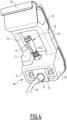
- the lifting platform 1 also includes a control console 40, which is illustrated in detail in the figures 2 to 7 .
- this desk 40 is provided with various manually operated control members allowing the operator to control the drive of the lifting structure 30 and, thereby, to cause in particular the movement in height of the platform 20 relative to the chassis 10, as well as, where appropriate, to control the movement of the chassis 10 on the ground.
- the console 40 comprises a main body 41 which has two faces opposite each other, namely a front face 41A and a rear face 41B.
- the front 41A and rear 41B faces are thus opposite each other in an anteroposterior direction of the main body 41.
- the front face 41A of the main body 41 is designed to be turned towards the operator when the console 40 is in use, that is to say when the operator uses the console for the purpose of controlling the lifting platform 1, as in the Figure 2 .
- the front face 41A is facing the reader on the figures 3 And 5
- the rear face 41B is facing the reader on the Figure 4 .
- the main body 41 comprises two crosspieces and two uprights, namely a lower crosspiece 42 and an upper crosspiece 43, and a left upright 44 and a right upright 45.
- the lower 42 and upper 43 crosspieces each extend over the entire width of the main body 41, the lower crosspiece 42 being located under the upper crosspiece 43 when the music stand 40 is in use.
- the left 44 and right 45 uprights each extend over the entire height of the main body 41 and, when the music stand 40 is in use, are respectively located to the left and right of the music stand when the latter is observed from the front face 41A of its main body 41, as in the Figure 5
- the lower cross member 42 connects to each other respective lower end portions of the left 44 and right 45 uprights.
- the left upright 44 connects to each other respective left end portions of the lower 42 and upper 43 cross members.
- the upper cross member 43 connects to each other respective upper end portions of the left 44 and right 45 uprights. right 45.
- the right upright 45 connects to each other the respective right end portions of the lower 42 and upper 43 crosspieces.
- the lower crosspiece 42 and the left upright 44 thus share the same lower left portion of the main body 41, this lower left portion corresponding to both the left end portion of the lower crosspiece 42 and the lower end portion of the left upright 44.
- the left upright 44 and the upper crosspiece 43 share the same upper left portion of the main body 41, this upper left portion corresponding to both the upper end portion of the left upright 44 and the left end portion of the upper crosspiece 43;
- the upper crosspiece 43 and the right upright 45 share the same upper right portion of the main body 41, this upper right portion corresponding to both the right end portion of the upper crosspiece 43 and the upper end portion of the right upright 45;
- the right upright 45 and the lower crosspiece 42 share the same right lower part of the main body 41, this right lower part corresponding to both the lower end part of the right upright 45 and the right end part of the lower crosspiece 42.
- the crosspieces 42 and 43 and the uprights 44 and 45 delimit between them a through passage 41C which connects the front 41A and rear 41B faces of the main body 41 to each other.
- the through passage 41C is open at its two opposite ends in the anteroposterior direction of the main body 41, opening onto the front 41A and rear 41B faces.
- the through passage 41C is closed by the crosspieces 42 and 43 and the uprights 44 and 45.
- the corresponding closed contour of the through passage 41C extends over 360°, as clearly visible in the Figure 5 In the example considered here, this closed contour is generally rectangular, with rounded corners.
- the desk 40 is designed to be fixed to the platform 20, in particular to the guardrail 22 of the latter.
- the desk 40 is designed to be thus fixed to the platform 20 in a removable manner.
- the desk 40 comprises a hook 46 making it possible to removably fix the desk 40 to the guardrail 22 of the platform 20.
- this hook 46 is arranged on the rear face 41B of the main body 41, preferably at the level of the upper crosspiece 43 of the main body 41.
- the hook 46 is shaped to cooperate by complementarity of shape with an upper bar 22.1 of the guardrail 22, extending parallel to the floor 21 of the platform 20.
- the hook 46 is advantageously available in different sizes in order to adapt to various possible dimensions for the constituents of the guardrail 22.
- console 40 When the console 40 is detached from the platform 20, it can be deactivated for storage purposes.
- the console 40 can also be kept activated and used to control the lifting platform 1: in this case, the operator holds the console 40 in his hand and, for this purpose, the left upright 44 is advantageously shaped into a handle for the operator's left hand.
- the console 40 is furthermore designed to be connected to a control unit 13 of the lifting platform 1, which, as shown schematically in the Figure 1 , is preferably integrated into the chassis 10.
- This control unit 13 comprises for example a microprocessor and is designed to, depending on the orders issued by the control members belonging to the console 40, actuate the motor members which ensure the driving of the lifting structure 30 relative to the chassis 10 and, if necessary, actuate the motorization which ensures the movement of the chassis 10 on the ground.
- the corresponding connection between the control console 40 and the control unit 13 is made by a cable 50 of which only the end connected to the console 40 is visible in the figures.
- the cable 50 makes it possible to transmit to the control unit 13 the orders issued by the control members belonging to the console 40.
- the cable 50 can also provide the electrical power supply to the console 40, the electrical energy supplied by the cable 50 being able to be consumed directly or else be stored in a battery integrated into the console 40.
- the cable 50 is advantageously designed to emerge from the rear face 41B of the main body 41, in particular for ergonomic reasons. This being the case, in a variant not shown, the cable 50 emerges downwards from the lower end of the lower crosspiece 42.
- the cable 50 is removably connectable to the desk 40: the desk 40 then integrates, in particular in its lower crosspiece 42, a connection socket 51, which is accessible from the rear face 41B of the main body 41 for the purpose of connecting the cable 50.
- this connection socket 51 is advantageously protected by a plate 52 which is attached to the rear face 41B of the main body 41 so as to lock the connection socket 51 and thus avoid disassembly or tampering with the latter, in particular for safety purposes.
- a lower edge 42A of the lower crosspiece 42 of the main body 41 is provided with a connection port 60, such as a USB port, which is accessible from the front face 41A of the main body 41.
- the purpose of the connection port connection 60 is not limiting but aims, in all cases, to improve the practicality of the console 40.
- the connection port 60 makes it possible to connect a mobile electronic device, such as a telephone, for the purpose of recharging it.
- the connection port 60 can also make it possible to connect a mobile terminal in order to exchange data between the latter and the console 40, for example for the purposes of control, updating, troubleshooting, etc.
- the desk 40 also includes a joystick 70 which forms one of the manually operated control members belonging to the desk.
- the joystick 70 is arranged inside the through passage 41C of the main body 41, extending upwards from the lower crosspiece 42.
- the joystick 70 is mounted on the lower crosspiece 42 in a movable manner, in particular tiltable, from a rest position that the joystick 70 occupies when it is at rest, that is to say in the absence of stress, in particular from the operator.
- the joystick 70 When the console 40 is in use, the joystick 70 is intended to be grasped by the operator's right hand, as shown schematically in the Figure 2 : the carpal region of the right hand is then located between the joystick 70 and the right upright 45 of the main body 41, while the fingers of the right hand are closed around the joystick 70 and the right arm of the operator emerges from the through passage 41C by the front face 41A of the main body 41.
- the desk 40 also includes a wrist rest 71 for the right hand of the operator holding the joystick 70, this wrist rest 71 being arranged in the lower right quadrant of the through passage 41C, as clearly visible in the figures 3 to 5 .
- the embodiment of the wrist rest 71 is not limiting: in the example envisaged in the figures, the wrist rest 71 is an added part, as illustrated in the Figure 7 , which is fixedly secured to the main body 41 by any suitable means.
- the joystick in the rest position is inclined backwards when the joystick is moved from bottom to top, as clearly visible in the figures 2 And 6 .
- This backward tilt contributes to the ergonomics of the desk 40.
- This tilt is preferably such that, when the desk 40 is in use, in particular fixed to the platform 20 while the floor 21 of the latter is horizontal, the joystick 70 in the rest position is inclined at 45°, plus or minus 5°, relative to the vertical. This tilt range enhances the ease of use of the desk 40 by the operator.
- the center 70A of the joystick 70 is located at a distance D from the floor 21 of the platform 20, which is advantageously between 91 and 95 cm, as illustrated schematically in the Figure 2 : in this way, in operation, the operator, who stands on the floor 21 and holds the joystick 70 in his right hand, has his right arm forming an obtuse angle at his elbow, which corresponds to a satisfactory position in terms of ergonomics for the operator, compared to a situation where the latter would have to bend his arm at a right angle.
- the embodiment of the joystick 70 is not limiting as long as the latter can be grasped by the right hand of the operator, as described above, and that the movement, by the operator, of the joystick 70 from its rest position generates a corresponding order for the purposes of controlling the lifting platform 1, in particular for the purposes of actuating the lifting structure 30.
- the joystick 70 multiple embodiments are conceivable for the joystick 70, the latter being able to integrate one or more buttons whose manual actuation modifies the order generated by the movement of the joystick 70.
- one of these buttons preferably constitutes a validation member 72, called a “dead man’s button”, so that a movement ordered by movement of the joystick 70 is only executed if the validation member 72 is actuated simultaneously.
- the backward tilting of the joystick 70 in the rest position is advantageously used to enhance the safety of use of the lifting platform 1, by providing that the joystick 70 is designed to, on the one hand, raise the platform 20 when the joystick is tilted forward from its rest position and, on the other hand, lower the platform 20 when the joystick is tilted backward from its rest position.
- the joystick 70 is designed to, on the one hand, raise the platform 20 when the joystick is tilted forward from its rest position and, on the other hand, lower the platform 20 when the joystick is tilted backward from its rest position.
- the front face 41A of the main body 41 includes a flat face 47, onto which the through passage 41C opens and which extends continuously over both the lower crosspiece 42, the left upright 44 and the upper crosspiece 43.
- the lower crosspiece 42 and upper crosspiece 43 and the left upright 44 have, on the front face 41A of the main body 41, respective surfaces, which, together, form the flat surface 47 and which are all inscribed in the same plane, connecting directly to each other without discontinuity, as clearly visible on the Figure 6 .
- the flat surface 47 is inclined backwards when it is traversed from bottom to top.
- the flat surface 47 is thus inclined parallel to the joystick 70 in the rest position.
- the backward inclination of the flat surface 47 makes it possible to orient the latter towards the operator holding the joystick 70, while making it possible to position the desk 40 in a lower portion of the operator's field of vision, which is particularly ergonomic and practical.
- the desk 40 thus positioned relatively low relative to the operator, only marginally limits the latter's field of vision, while maintaining the flat surface 47 oriented directly towards the operator, in particular, as explained below, for the purposes of observing this flat surface 47 and actuating control members carried by this flat surface 47.
- the flat surface 47 is provided with a display 80.
- the display 80 is in particular provided for transmitting visual information to the operator.
- the display 80 thus improves the operator's handling of the console 40, by facilitating the latter's understanding during operation of the console, and also allows for in-service monitoring.
- the embodiment of the display 80 is not limiting.
- the display 80 comprises an electronic screen, protected by a transparent covering plate.
- the flat surface 47 is advantageously provided with an emergency stop button 90, which is known per se and the actuation of which causes the lifting platform 1 to be de-energized.
- the emergency stop button 90 is advantageously located to the right of the display 80, for ergonomic reasons with a view to its actuation by the operator's right hand.
- the flat surface 47 is provided with push buttons 100, which correspond to some of the manually operated control members belonging to the console 40.
- the actuation of each of the push buttons 100 makes it possible to activate/deactivate a predetermined function linked to the control of the lifting platform 1, this technical aspect being known per se in the field and therefore not being detailed here further.
- the arrangement of the push buttons 100 on the flat surface 47 at the left upright 44 is particularly practical and ergonomic, in particular allowing the actuation of these push buttons 100 by the left hand of the operator when the latter holds the joystick 70 with his right hand, including when the left hand of the operator holds the left upright 44 since the user can then use his left thumb to actuate at least some of the push buttons 100.
- all or part of the push buttons 100 are advantageously distributed along the left upright 44, as in the example illustrated in the figures.
- the embodiment of the push buttons 100 is not limiting.
- the push buttons 100 are flat push buttons.
- the push buttons 100 integrate a light return function, which illuminates the push button when the latter is activated.
- the flat surface 47 runs from the through passage 41C to the lower edge 42A of the lower cross member 42, which is provided set back from the flat surface 47, as clearly visible in the figures 3 And 6 .
- the lower edge 42A is therefore non-protruding relative to the flat surface 47.
- water or dirt avoids accumulating on the flat surface 47 because, due to the inclination of the latter, water, such as rainwater, falling on the flat surface 47 tends to flow there by gravity to the lower edge 42A where the water is freely evacuated from the desk 40, in particular without being retained by the lower edge 42A due to the arrangement of the latter set back from the flat surface 47.
- the lower edge 42A is not set back relative to the flat surface 47 over the entire extent of this lower edge between the left 44 and right 45 uprights of the main body 41, but is thus set back to the left and right of a localized bulge of the lower edge 42A, where is arranged the connection port 60.
- the water flowing over the flat surface 47 is evacuated therefrom at the level of the lower edge 42A, passing on either side of this bulge.
- the flat surface 47 is divided into three zones which are identified on the Figure 5 , namely a first zone 47.1, which is located in vertical alignment with the joystick 70, a second zone 47.2, which connects the first zone 47.1 to the right upright 45 of the main body 41, and a third zone 47.3, which connects the first zone 47.1 to the left upright 44.
- the first and second zones 47.1 and 47.2 are advantageously devoid of any control member: in this way, the right arm of the operator, whose right hand holds the joystick 70, does not hinder or hide control members which would have been provided in one and/or the other of the zones 47.1 and 47.2 of the flat surface 47.
- the third zone 47.3 of the flat surface 47 is not located directly above the right arm of the operator and can therefore carry control members, in this case, in the embodiment considered here, certain 100 push buttons.
- the front face 41A of the main body 41 comprises a rim 48, which projects relative to the flat surface 47 and which runs over a part of the periphery of this flat surface, so that the edge of the rim 48, facing forward, defines a front support plane PA, set back from which the joystick 70 in the rest position and the push buttons 100 are arranged, as clearly visible in the Figure 6 .
- the rim 48 runs over the entire periphery of the flat surface 47, except on the lower edge 42A of the lower crosspiece 42.
- the rim 48 protects the flat surface 47 and the elements that it carries, in the sense that the front support plane PA that geometrically defines the front edge of the rim 48 prevents an external obstacle extending across the face 41A from interfering with the flat surface 47, by being held in abutment against the front support plane PA. This situation occurs for example in the case where the desk 40 falls to the ground, against its front face 41A.
- the top of the emergency stop button 90 can be arranged protruding from the front support plane PA, as in the example envisaged in the figures: in this case, only the activation of the emergency stop button 90 is possible in the event of the desk 40 falling against its front face 41A or, more generally, in the event of interference between the front face 41A and an obstacle extending across the latter.
- the rear face 41B of the main body 41 advantageously defines a rear support plane PB, set back from which the joystick 70 is arranged in the rest position, as clearly visible in the Figure 6
- the rear support plane PB is defined by the rear of the lower 42 and upper 43 crosspieces.
- the desk 40 comprises a flexible protective cover 110, for example made of an extensible plastic material.
- This protective cover 110 is adapted to removably cover at least the flat surface 47, or even the entire front face 41A of the main body 41, as indicated in dotted lines on the Figure 6 .
- the protective cover 110 thus protects the flat surface 47, or even the entire front face 41A, from rain and, more generally, from bad weather and external conditions.
- the protective cover 110 is provided to be transparent at least in its part which covers the display 80 when the protective cover 110 covers the flat surface 47.
- the protective hood 110 is permanently fixed on one of the lower 42 and upper 43 crossbars and is deployable to the other of these lower 42 and upper 43 crossbars, with which the protective hood cooperates to be retained reversibly, and this by any appropriate means.
- a reel is provided on the crosspiece to which the protective hood 110 is permanently fixed, so that the latter wraps around the reel when it does not cover the flat surface 47.
- the protective hood 110 forms a cover that is completely removable from the main body 41.
- the desk 40 comprises a protective cover, at least partially rigid, which removably covers at least the flat surface 47, or even the entire front face 41A of the main body 41.
- This cover can in particular be either formed from a single piece, separable or mounted in a movably manner relative to the main body 41, or formed from several pieces which can be retracted relative to each other.
Landscapes
- Engineering & Computer Science (AREA)
- Structural Engineering (AREA)
- Life Sciences & Earth Sciences (AREA)
- Geology (AREA)
- Mechanical Engineering (AREA)
- Transportation (AREA)
- General Physics & Mathematics (AREA)
- Automation & Control Theory (AREA)
- Physics & Mathematics (AREA)
- Civil Engineering (AREA)
- Mechanical Control Devices (AREA)
- Forklifts And Lifting Vehicles (AREA)
- Harvester Elements (AREA)
- Tables And Desks Characterized By Structural Shape (AREA)
Claims (15)
- Bedienkonsole (40) für eine Personenhebemaschine (1), wobei die Konsole einen Hauptkörper (41) umfasst, der eine Vorderseite (41A) und eine Rückseite (41B) aufweist, die durch einen Durchgang (41C) miteinander verbunden sind, der sowohl von einer unteren (42) und einer oberen (43) Querstrebe des Hauptkörpers geschlossen wird, die sich jeweils über die gesamte Breite des Hauptkörpers erstrecken, als auch von einem linken (44) und einem rechten (45) Träger, die sich jeweils über die gesamte Höhe des Hauptkörpers erstrecken, durchquert werden,
wobei die Konsole einen Joystick (70) aufweist, der innerhalb des Durchgangs angeordnet ist, indem er sich von der unteren Querstrebe nach oben erstreckt, und der im Ruhezustand eine Ruheposition einnimmt, in der, wenn die Konsole in Betrieb ist, der Joystick nach hinten geneigt ist, wenn der Joystick von unten nach oben bewegt wird, und dadurch gekennzeichnet, dass die Vorderseite des Hauptkörpers eine ebene Fläche (47) beinhaltet:- auf die der Durchgang mündet,- die, wenn die Konsole in Betrieb ist, nach hinten geneigt ist, wenn die ebene Fläche von unten nach oben bewegt wird, und- die sich durchgehend sowohl über den oberen Querträger, wo die ebene Fläche mit einer Anzeige (80) versehen ist, über den linken Träger, wo die ebene Fläche mit Druckknöpfen (100) versehen ist, als auch über den unteren Querträger erstreckt, wo die ebene Fläche von dem Durchgang bis zu einem unteren Rand (42A) des unteren Querträgers verläuft, wobei dieser untere Rand zumindest in einem Teil ihrer Erstreckung zwischen dem linken und rechten Träger gegenüber der ebenen Fläche zurückgesetzt ist. - Konsole nach Anspruch 1,
wobei die ebene Fläche (47) an der unteren Querstrebe (42) einen ersten Bereich (47.1), der in vertikaler Ausrichtung mit dem Joystick (70) angeordnet ist, und einen zweiten Bereich (47.(2), der den ersten Bereich mit dem rechten Träger (45) verbindet, und wobei der erste und der zweite Bereich der ebenen Fläche frei von jeglichen Bedienelementen sind. - Konsole nach einem der Ansprüche 1 oder 2, wobei die ebene Fläche (47) auf der oberen Querstrebe (43) mit einem Not-Aus-Knopf (90) versehen ist, der sich insbesondere rechts neben der Anzeige (80) befindet.
- Konsole nach einem der Ansprüche 1 bis 3, wobei die Vorderseite (41A) des Hauptkörpers (41) eine Kante (48) umfasst, die von der ebenen Fläche (47) hervorsteht und über einen Teil des Umfangs der ebenen Fläche verläuft, sodass der nach vorne gerichtete Abschnitt der Kante eine vordere Auflageebene (PA) definiert, von der der Joystick (70) in der Ruhestellung und die Druckknöpfe (100) zurückversetzt sind.
- Konsole nach einem der vorherigen Ansprüche, wobei die Rückseite (41 B) des Hauptkörpers (41) eine hintere Auflageebene (PB) definiert, von der der Joystick (70) in der Ruhestellung zurückversetzt angeordnet ist.
- Konsole nach einem der vorherigen Ansprüche, wobei der linke Träger (44) zu einem Griff für die linke Hand eines Bedieners geformt ist, der die Konsole (40) benutzt.
- Konsole nach einem der vorherigen Ansprüche, wobei, wenn die Konsole (40) in Betrieb ist, der Joystick (70) in der Ruheposition um 45°, plus oder minus 5°, in Bezug auf die Vertikale geneigt ist.
- Konsole nach einem der vorherigen Ansprüche, wobei der untere Querträger (42) mit einem Anschluss (60), wie beispielsweise einem USB-Anschluss, versehen ist, der von der Vorderseite (41A) des Hauptkörpers (41) aus zugänglich ist und an dem unteren Rand (42A) des unteren Querträgers außerhalb des genannten Abschnitts dieses unteren Rands angeordnet ist.
- Konsole nach einem der vorherigen Ansprüche, wobei die Konsole (40) eine Handgelenkauflage (71) für die rechte Hand eines Bedieners, der den Joystick (70) hält, aufweist, wobei die Handgelenkauflage unten rechts in dem Durchgang (41C) angeordnet ist.
- Konsole nach einem der vorherigen Ansprüche, wobei die Konsole (40) auch einen Haken (46) zum lösbaren Befestigen an einem Geländer (22) einer Plattform (20) der Personenhebemaschine (1) umfasst, wobei dieser Haken an der Rückseite (41 B) des Hauptkörpers (41) angeordnet und fest mit der oberen Querstrebe (43) verbunden ist.
- Konsole nach einem der vorherigen Ansprüche, wobei die Konsole (40) eine flexible Schutzhaube (110) aufweist, die angepasst ist, um die ebene Oberfläche (47) abnehmbar abzudecken, und die zumindest in dem Teil, der die Anzeige (80) abdeckt, transparent ist, wenn die Schutzhaube die ebene Fläche (47) abdeckt.
- Konsole nach Anspruch 11, wobei die Schutzhaube (110) fest an einer von der oberen (43) und der unteren (42) Querstrebe befestigt ist und bis zu der anderen von der unteren und der oberen Querträger entfaltbar ist, mit dem die Schutzhaube zusammenwirkt, um reversibel gehalten zu werden.
- Personenhebemaschine (1), umfassend:- ein Gestell (10) zum Abstützen auf dem Boden,- eine Plattform (20), die angepasst ist, damit mindestens ein Bediener darauf stehen kann,- eine Hebestruktur (30), die die Plattform trägt und auf dem Fahrgestell angeordnet ist, um die Plattform in Bezug auf das Gestell mehr oder weniger anzuheben, und- eine Bedienkonsole (40), die einem der vorherigen Ansprüche entspricht und fest oder lösbar an der Plattform (20) befestigt ist.
- Maschine nach Anspruch 13, wobei die Mitte (70A) des Joysticks (70) zwischen 91 und 95 cm von einem Boden (21) der Plattform (20) entfernt ist, wenn die Konsole (40) an der Plattform befestigt ist.
- Maschine nach einem der Ansprüche 13 oder 14, wobei der Joystick (70) zu Folgendem ausgelegt ist:- Bewirken eines Anhebens der Plattform (20), wenn der Joystick aus seiner Ruheposition nach vorne gekippt wird, und- Bewirken eines Absenkens der Plattform, wenn der Joystick aus der Ruheposition nach hinten gekippt wird.
Applications Claiming Priority (2)
| Application Number | Priority Date | Filing Date | Title |
|---|---|---|---|
| FR2106326A FR3123907B1 (fr) | 2021-06-15 | 2021-06-15 | Pupitre de commande pour une machine d’élévation de personnes, ainsi que machine d’élévation de personnes comprenant un tel pupitre de commande |
| PCT/EP2022/066198 WO2022263455A1 (fr) | 2021-06-15 | 2022-06-14 | Pupitre de commande pour une machine d'élévation de personnes, ainsi que machine d'élévation de personnes comprenant un tel pupitre de commande |
Publications (2)
| Publication Number | Publication Date |
|---|---|
| EP4355682A1 EP4355682A1 (de) | 2024-04-24 |
| EP4355682B1 true EP4355682B1 (de) | 2025-04-23 |
Family
ID=76807873
Family Applications (1)
| Application Number | Title | Priority Date | Filing Date |
|---|---|---|---|
| EP22732588.3A Active EP4355682B1 (de) | 2021-06-15 | 2022-06-14 | Steuerkonsole für eine personenhebemaschine und personenhebemaschine mit solch einer steuerkonsole |
Country Status (7)
| Country | Link |
|---|---|
| US (1) | US20240295896A1 (de) |
| EP (1) | EP4355682B1 (de) |
| CN (1) | CN117500744A (de) |
| AU (1) | AU2022292081A1 (de) |
| CA (1) | CA3220910A1 (de) |
| FR (1) | FR3123907B1 (de) |
| WO (1) | WO2022263455A1 (de) |
Family Cites Families (3)
| Publication number | Priority date | Publication date | Assignee | Title |
|---|---|---|---|---|
| EP3440526B1 (de) * | 2016-04-07 | 2021-11-17 | JLG Industries, Inc. | Steuerkasten und bedienerschnittstelle für ein industriefahrzeug |
| FR3091524B1 (fr) | 2019-01-09 | 2021-10-29 | Haulotte Group | Nacelle elevatrice a pupitre de commande amovible comprenant une protection anti-ecrasement de l’operateur |
| EP3947248B1 (de) * | 2019-04-05 | 2025-08-20 | Oshkosh Corporation | Plattformsteuerkasten |
-
2021
- 2021-06-15 FR FR2106326A patent/FR3123907B1/fr active Active
-
2022
- 2022-06-14 US US18/569,929 patent/US20240295896A1/en active Pending
- 2022-06-14 CA CA3220910A patent/CA3220910A1/fr active Pending
- 2022-06-14 CN CN202280042649.2A patent/CN117500744A/zh active Pending
- 2022-06-14 EP EP22732588.3A patent/EP4355682B1/de active Active
- 2022-06-14 AU AU2022292081A patent/AU2022292081A1/en active Pending
- 2022-06-14 WO PCT/EP2022/066198 patent/WO2022263455A1/fr not_active Ceased
Also Published As
| Publication number | Publication date |
|---|---|
| EP4355682A1 (de) | 2024-04-24 |
| AU2022292081A1 (en) | 2024-01-04 |
| CN117500744A (zh) | 2024-02-02 |
| FR3123907B1 (fr) | 2023-06-23 |
| FR3123907A1 (fr) | 2022-12-16 |
| CA3220910A1 (fr) | 2022-12-22 |
| US20240295896A1 (en) | 2024-09-05 |
| WO2022263455A1 (fr) | 2022-12-22 |
Similar Documents
| Publication | Publication Date | Title |
|---|---|---|
| EP3908547B1 (de) | Hubarbeitsbühne mit abnehmbarer steuerkonsole, mit einer schutzvorrichtung zur verhinderung von quetschungen der bedienperson | |
| EP3386901B1 (de) | Steuerstation für arbeitsbühne eines freileitungslifts | |
| EP0556143B1 (de) | Mähmaschine mit einer verbesserten Verriegelungsvorrichtung | |
| EP2794460B1 (de) | Hydraulische arbeitsbühne mit einem leitstand | |
| CA2434397A1 (fr) | Table d'operation motorisee a multiples sections | |
| FR2894429A1 (fr) | Collecteur d'herbe pour une tondeuse | |
| EP0511922B1 (de) | Mähmaschine mit schwenkbarer Kupplungsstruktur | |
| EP0552120B1 (de) | Heumaschine mit dynamischer Entlastungsvorrichtung | |
| WO2015004178A1 (fr) | Plateforme de nacelle élévatrice et nacelle élévatrice équipée d'une telle plateforme | |
| FR2871989A1 (fr) | Collecteur d'herbe et tondeuse a gazon pourvue du collecteur d'herbe | |
| WO2018020114A1 (fr) | Poste auxiliaire de commande de nacelle elevatrice | |
| EP0172762A1 (de) | Gehäuse für Datengeräte | |
| EP4355682B1 (de) | Steuerkonsole für eine personenhebemaschine und personenhebemaschine mit solch einer steuerkonsole | |
| FR2940880A1 (fr) | Unite de tondeuse avec dispositif de reglage d'ouverture d'entree d'air. | |
| FR2887396A1 (fr) | Tondeuse a gazon autoportee ayant une unite de tondeuse frontale | |
| EP2810825B1 (de) | Vorrichtung zum Rückwärtssehen für ein Kraftfahrzeug | |
| FR2887504A1 (fr) | Rampe escamotable d'acces a un vehicule, vehicule de transport public notamment | |
| EP0558431B1 (de) | Mähmaschine mit einem verbesserten Schutzorgan | |
| EP2179640A1 (de) | Maschine zum Abschneiden von Pflanzen | |
| FR2821816A1 (fr) | Timon articule pour chariot de magasinage | |
| CA3007572C (fr) | Poste de commande pour plate-forme de travail de nacelle elevatrice | |
| EP4116796A1 (de) | Vorrichtung zur steuerung einer oder mehrerer arbeitsfunktionen einer landmaschine und landmaschine mit dieser steuerungsvorrichtung | |
| FR3003226A3 (fr) | Appareil de jardinage guide a la main, muni d'un guidon a plusieurs positions | |
| EP1650100A1 (de) | Auf Rollen montierte Vorrichtung zur Behandlung von Nahrungsmitteln | |
| FR3070312A1 (fr) | Vehicule motorise multifonction |
Legal Events
| Date | Code | Title | Description |
|---|---|---|---|
| STAA | Information on the status of an ep patent application or granted ep patent |
Free format text: STATUS: UNKNOWN |
|
| STAA | Information on the status of an ep patent application or granted ep patent |
Free format text: STATUS: THE INTERNATIONAL PUBLICATION HAS BEEN MADE |
|
| PUAI | Public reference made under article 153(3) epc to a published international application that has entered the european phase |
Free format text: ORIGINAL CODE: 0009012 |
|
| STAA | Information on the status of an ep patent application or granted ep patent |
Free format text: STATUS: REQUEST FOR EXAMINATION WAS MADE |
|
| 17P | Request for examination filed |
Effective date: 20231213 |
|
| AK | Designated contracting states |
Kind code of ref document: A1 Designated state(s): AL AT BE BG CH CY CZ DE DK EE ES FI FR GB GR HR HU IE IS IT LI LT LU LV MC MK MT NL NO PL PT RO RS SE SI SK SM TR |
|
| DAV | Request for validation of the european patent (deleted) | ||
| DAX | Request for extension of the european patent (deleted) | ||
| GRAP | Despatch of communication of intention to grant a patent |
Free format text: ORIGINAL CODE: EPIDOSNIGR1 |
|
| STAA | Information on the status of an ep patent application or granted ep patent |
Free format text: STATUS: GRANT OF PATENT IS INTENDED |
|
| INTG | Intention to grant announced |
Effective date: 20250127 |
|
| GRAS | Grant fee paid |
Free format text: ORIGINAL CODE: EPIDOSNIGR3 |
|
| GRAA | (expected) grant |
Free format text: ORIGINAL CODE: 0009210 |
|
| STAA | Information on the status of an ep patent application or granted ep patent |
Free format text: STATUS: THE PATENT HAS BEEN GRANTED |
|
| AK | Designated contracting states |
Kind code of ref document: B1 Designated state(s): AL AT BE BG CH CY CZ DE DK EE ES FI FR GB GR HR HU IE IS IT LI LT LU LV MC MK MT NL NO PL PT RO RS SE SI SK SM TR |
|
| REG | Reference to a national code |
Ref country code: GB Ref legal event code: FG4D Free format text: NOT ENGLISH |
|
| REG | Reference to a national code |
Ref country code: CH Ref legal event code: EP |
|
| REG | Reference to a national code |
Ref country code: DE Ref legal event code: R096 Ref document number: 602022013618 Country of ref document: DE |
|
| REG | Reference to a national code |
Ref country code: IE Ref legal event code: FG4D Free format text: LANGUAGE OF EP DOCUMENT: FRENCH |
|
| PGFP | Annual fee paid to national office [announced via postgrant information from national office to epo] |
Ref country code: DE Payment date: 20250617 Year of fee payment: 4 |
|
| PGFP | Annual fee paid to national office [announced via postgrant information from national office to epo] |
Ref country code: FR Payment date: 20250515 Year of fee payment: 4 |
|
| PGFP | Annual fee paid to national office [announced via postgrant information from national office to epo] |
Ref country code: AT Payment date: 20250721 Year of fee payment: 4 |
|
| PGFP | Annual fee paid to national office [announced via postgrant information from national office to epo] |
Ref country code: TR Payment date: 20250529 Year of fee payment: 4 |
|
| REG | Reference to a national code |
Ref country code: NL Ref legal event code: MP Effective date: 20250423 |
|
| PG25 | Lapsed in a contracting state [announced via postgrant information from national office to epo] |
Ref country code: NL Free format text: LAPSE BECAUSE OF FAILURE TO SUBMIT A TRANSLATION OF THE DESCRIPTION OR TO PAY THE FEE WITHIN THE PRESCRIBED TIME-LIMIT Effective date: 20250423 |
|
| REG | Reference to a national code |
Ref country code: AT Ref legal event code: MK05 Ref document number: 1787624 Country of ref document: AT Kind code of ref document: T Effective date: 20250423 |
|
| PG25 | Lapsed in a contracting state [announced via postgrant information from national office to epo] |
Ref country code: PT Free format text: LAPSE BECAUSE OF FAILURE TO SUBMIT A TRANSLATION OF THE DESCRIPTION OR TO PAY THE FEE WITHIN THE PRESCRIBED TIME-LIMIT Effective date: 20250825 Ref country code: FI Free format text: LAPSE BECAUSE OF FAILURE TO SUBMIT A TRANSLATION OF THE DESCRIPTION OR TO PAY THE FEE WITHIN THE PRESCRIBED TIME-LIMIT Effective date: 20250423 Ref country code: ES Free format text: LAPSE BECAUSE OF FAILURE TO SUBMIT A TRANSLATION OF THE DESCRIPTION OR TO PAY THE FEE WITHIN THE PRESCRIBED TIME-LIMIT Effective date: 20250423 |
|
| REG | Reference to a national code |
Ref country code: LT Ref legal event code: MG9D |
|
| PG25 | Lapsed in a contracting state [announced via postgrant information from national office to epo] |
Ref country code: NO Free format text: LAPSE BECAUSE OF FAILURE TO SUBMIT A TRANSLATION OF THE DESCRIPTION OR TO PAY THE FEE WITHIN THE PRESCRIBED TIME-LIMIT Effective date: 20250723 Ref country code: GR Free format text: LAPSE BECAUSE OF FAILURE TO SUBMIT A TRANSLATION OF THE DESCRIPTION OR TO PAY THE FEE WITHIN THE PRESCRIBED TIME-LIMIT Effective date: 20250724 |
|
| PG25 | Lapsed in a contracting state [announced via postgrant information from national office to epo] |
Ref country code: PL Free format text: LAPSE BECAUSE OF FAILURE TO SUBMIT A TRANSLATION OF THE DESCRIPTION OR TO PAY THE FEE WITHIN THE PRESCRIBED TIME-LIMIT Effective date: 20250423 |
|
| PGFP | Annual fee paid to national office [announced via postgrant information from national office to epo] |
Ref country code: IT Payment date: 20250630 Year of fee payment: 4 |
|
| PG25 | Lapsed in a contracting state [announced via postgrant information from national office to epo] |
Ref country code: BG Free format text: LAPSE BECAUSE OF FAILURE TO SUBMIT A TRANSLATION OF THE DESCRIPTION OR TO PAY THE FEE WITHIN THE PRESCRIBED TIME-LIMIT Effective date: 20250423 |
|
| PG25 | Lapsed in a contracting state [announced via postgrant information from national office to epo] |
Ref country code: AT Free format text: LAPSE BECAUSE OF FAILURE TO SUBMIT A TRANSLATION OF THE DESCRIPTION OR TO PAY THE FEE WITHIN THE PRESCRIBED TIME-LIMIT Effective date: 20250423 Ref country code: HR Free format text: LAPSE BECAUSE OF FAILURE TO SUBMIT A TRANSLATION OF THE DESCRIPTION OR TO PAY THE FEE WITHIN THE PRESCRIBED TIME-LIMIT Effective date: 20250423 |
|
| PG25 | Lapsed in a contracting state [announced via postgrant information from national office to epo] |
Ref country code: RS Free format text: LAPSE BECAUSE OF FAILURE TO SUBMIT A TRANSLATION OF THE DESCRIPTION OR TO PAY THE FEE WITHIN THE PRESCRIBED TIME-LIMIT Effective date: 20250723 |
|
| PG25 | Lapsed in a contracting state [announced via postgrant information from national office to epo] |
Ref country code: IS Free format text: LAPSE BECAUSE OF FAILURE TO SUBMIT A TRANSLATION OF THE DESCRIPTION OR TO PAY THE FEE WITHIN THE PRESCRIBED TIME-LIMIT Effective date: 20250823 |
|
| PG25 | Lapsed in a contracting state [announced via postgrant information from national office to epo] |
Ref country code: LV Free format text: LAPSE BECAUSE OF FAILURE TO SUBMIT A TRANSLATION OF THE DESCRIPTION OR TO PAY THE FEE WITHIN THE PRESCRIBED TIME-LIMIT Effective date: 20250423 |
|
| PG25 | Lapsed in a contracting state [announced via postgrant information from national office to epo] |
Ref country code: DK Free format text: LAPSE BECAUSE OF FAILURE TO SUBMIT A TRANSLATION OF THE DESCRIPTION OR TO PAY THE FEE WITHIN THE PRESCRIBED TIME-LIMIT Effective date: 20250423 Ref country code: SM Free format text: LAPSE BECAUSE OF FAILURE TO SUBMIT A TRANSLATION OF THE DESCRIPTION OR TO PAY THE FEE WITHIN THE PRESCRIBED TIME-LIMIT Effective date: 20250423 |
|
| PG25 | Lapsed in a contracting state [announced via postgrant information from national office to epo] |
Ref country code: CZ Free format text: LAPSE BECAUSE OF FAILURE TO SUBMIT A TRANSLATION OF THE DESCRIPTION OR TO PAY THE FEE WITHIN THE PRESCRIBED TIME-LIMIT Effective date: 20250423 |
|
| PG25 | Lapsed in a contracting state [announced via postgrant information from national office to epo] |
Ref country code: EE Free format text: LAPSE BECAUSE OF FAILURE TO SUBMIT A TRANSLATION OF THE DESCRIPTION OR TO PAY THE FEE WITHIN THE PRESCRIBED TIME-LIMIT Effective date: 20250423 |
|
| PG25 | Lapsed in a contracting state [announced via postgrant information from national office to epo] |
Ref country code: SK Free format text: LAPSE BECAUSE OF FAILURE TO SUBMIT A TRANSLATION OF THE DESCRIPTION OR TO PAY THE FEE WITHIN THE PRESCRIBED TIME-LIMIT Effective date: 20250423 |
|
| REG | Reference to a national code |
Ref country code: CH Ref legal event code: H13 Free format text: ST27 STATUS EVENT CODE: U-0-0-H10-H13 (AS PROVIDED BY THE NATIONAL OFFICE) Effective date: 20260127 |
|
| PG25 | Lapsed in a contracting state [announced via postgrant information from national office to epo] |
Ref country code: MC Free format text: LAPSE BECAUSE OF FAILURE TO SUBMIT A TRANSLATION OF THE DESCRIPTION OR TO PAY THE FEE WITHIN THE PRESCRIBED TIME-LIMIT Effective date: 20250423 |
|
| PG25 | Lapsed in a contracting state [announced via postgrant information from national office to epo] |
Ref country code: LU Free format text: LAPSE BECAUSE OF NON-PAYMENT OF DUE FEES Effective date: 20250614 |