EP4355047A2 - Technologie pour avortement précoce d'accélération de compression - Google Patents
Technologie pour avortement précoce d'accélération de compression Download PDFInfo
- Publication number
- EP4355047A2 EP4355047A2 EP24157172.8A EP24157172A EP4355047A2 EP 4355047 A2 EP4355047 A2 EP 4355047A2 EP 24157172 A EP24157172 A EP 24157172A EP 4355047 A2 EP4355047 A2 EP 4355047A2
- Authority
- EP
- European Patent Office
- Prior art keywords
- compression
- early
- abort
- accelerator
- size
- Prior art date
- Legal status (The legal status is an assumption and is not a legal conclusion. Google has not performed a legal analysis and makes no representation as to the accuracy of the status listed.)
- Pending
Links
- 238000007906 compression Methods 0.000 title claims abstract description 212
- 230000006835 compression Effects 0.000 title claims abstract description 207
- 230000001133 acceleration Effects 0.000 title description 8
- 238000005516 engineering process Methods 0.000 title description 5
- 238000000034 method Methods 0.000 claims abstract description 62
- 230000006870 function Effects 0.000 claims description 5
- 230000008569 process Effects 0.000 abstract description 42
- 206010000210 abortion Diseases 0.000 abstract description 4
- 238000012545 processing Methods 0.000 description 60
- 230000015654 memory Effects 0.000 description 28
- 238000004891 communication Methods 0.000 description 12
- 238000010586 diagram Methods 0.000 description 10
- 230000006837 decompression Effects 0.000 description 7
- IUVCFHHAEHNCFT-INIZCTEOSA-N 2-[(1s)-1-[4-amino-3-(3-fluoro-4-propan-2-yloxyphenyl)pyrazolo[3,4-d]pyrimidin-1-yl]ethyl]-6-fluoro-3-(3-fluorophenyl)chromen-4-one Chemical compound C1=C(F)C(OC(C)C)=CC=C1C(C1=C(N)N=CN=C11)=NN1[C@@H](C)C1=C(C=2C=C(F)C=CC=2)C(=O)C2=CC(F)=CC=C2O1 IUVCFHHAEHNCFT-INIZCTEOSA-N 0.000 description 4
- 238000013459 approach Methods 0.000 description 4
- 230000008901 benefit Effects 0.000 description 4
- 239000004020 conductor Substances 0.000 description 3
- 230000014509 gene expression Effects 0.000 description 3
- 230000004044 response Effects 0.000 description 3
- SLXKOJJOQWFEFD-UHFFFAOYSA-N 6-aminohexanoic acid Chemical group NCCCCCC(O)=O SLXKOJJOQWFEFD-UHFFFAOYSA-N 0.000 description 2
- 238000003491 array Methods 0.000 description 2
- 230000008859 change Effects 0.000 description 2
- 238000013144 data compression Methods 0.000 description 2
- 238000013500 data storage Methods 0.000 description 2
- 238000013461 design Methods 0.000 description 2
- 238000004519 manufacturing process Methods 0.000 description 2
- 230000037361 pathway Effects 0.000 description 2
- 230000003068 static effect Effects 0.000 description 2
- 231100000176 abortion Toxicity 0.000 description 1
- 238000004458 analytical method Methods 0.000 description 1
- 239000000470 constituent Substances 0.000 description 1
- 230000008878 coupling Effects 0.000 description 1
- 238000010168 coupling process Methods 0.000 description 1
- 238000005859 coupling reaction Methods 0.000 description 1
- 230000003247 decreasing effect Effects 0.000 description 1
- 230000005611 electricity Effects 0.000 description 1
- 239000000203 mixture Substances 0.000 description 1
- 238000012986 modification Methods 0.000 description 1
- 230000004048 modification Effects 0.000 description 1
- 230000003287 optical effect Effects 0.000 description 1
- 230000002093 peripheral effect Effects 0.000 description 1
- 230000011664 signaling Effects 0.000 description 1
- 239000007787 solid Substances 0.000 description 1
- 238000001228 spectrum Methods 0.000 description 1
Images


Classifications
-
- G—PHYSICS
- G06—COMPUTING; CALCULATING OR COUNTING
- G06F—ELECTRIC DIGITAL DATA PROCESSING
- G06F3/00—Input arrangements for transferring data to be processed into a form capable of being handled by the computer; Output arrangements for transferring data from processing unit to output unit, e.g. interface arrangements
- G06F3/06—Digital input from, or digital output to, record carriers, e.g. RAID, emulated record carriers or networked record carriers
- G06F3/0601—Interfaces specially adapted for storage systems
- G06F3/0602—Interfaces specially adapted for storage systems specifically adapted to achieve a particular effect
- G06F3/0608—Saving storage space on storage systems
-
- G—PHYSICS
- G06—COMPUTING; CALCULATING OR COUNTING
- G06F—ELECTRIC DIGITAL DATA PROCESSING
- G06F12/00—Accessing, addressing or allocating within memory systems or architectures
- G06F12/02—Addressing or allocation; Relocation
- G06F12/08—Addressing or allocation; Relocation in hierarchically structured memory systems, e.g. virtual memory systems
- G06F12/0802—Addressing of a memory level in which the access to the desired data or data block requires associative addressing means, e.g. caches
- G06F12/0875—Addressing of a memory level in which the access to the desired data or data block requires associative addressing means, e.g. caches with dedicated cache, e.g. instruction or stack
-
- G—PHYSICS
- G06—COMPUTING; CALCULATING OR COUNTING
- G06F—ELECTRIC DIGITAL DATA PROCESSING
- G06F3/00—Input arrangements for transferring data to be processed into a form capable of being handled by the computer; Output arrangements for transferring data from processing unit to output unit, e.g. interface arrangements
- G06F3/06—Digital input from, or digital output to, record carriers, e.g. RAID, emulated record carriers or networked record carriers
- G06F3/0601—Interfaces specially adapted for storage systems
- G06F3/0602—Interfaces specially adapted for storage systems specifically adapted to achieve a particular effect
- G06F3/061—Improving I/O performance
-
- G—PHYSICS
- G06—COMPUTING; CALCULATING OR COUNTING
- G06F—ELECTRIC DIGITAL DATA PROCESSING
- G06F12/00—Accessing, addressing or allocating within memory systems or architectures
- G06F12/02—Addressing or allocation; Relocation
- G06F12/0223—User address space allocation, e.g. contiguous or non contiguous base addressing
- G06F12/023—Free address space management
- G06F12/0238—Memory management in non-volatile memory, e.g. resistive RAM or ferroelectric memory
- G06F12/0246—Memory management in non-volatile memory, e.g. resistive RAM or ferroelectric memory in block erasable memory, e.g. flash memory
-
- G—PHYSICS
- G06—COMPUTING; CALCULATING OR COUNTING
- G06F—ELECTRIC DIGITAL DATA PROCESSING
- G06F12/00—Accessing, addressing or allocating within memory systems or architectures
- G06F12/02—Addressing or allocation; Relocation
- G06F12/0223—User address space allocation, e.g. contiguous or non contiguous base addressing
- G06F12/023—Free address space management
- G06F12/0238—Memory management in non-volatile memory, e.g. resistive RAM or ferroelectric memory
-
- G—PHYSICS
- G06—COMPUTING; CALCULATING OR COUNTING
- G06F—ELECTRIC DIGITAL DATA PROCESSING
- G06F12/00—Accessing, addressing or allocating within memory systems or architectures
- G06F12/02—Addressing or allocation; Relocation
- G06F12/06—Addressing a physical block of locations, e.g. base addressing, module addressing, memory dedication
- G06F12/0638—Combination of memories, e.g. ROM and RAM such as to permit replacement or supplementing of words in one module by words in another module
-
- G—PHYSICS
- G06—COMPUTING; CALCULATING OR COUNTING
- G06F—ELECTRIC DIGITAL DATA PROCESSING
- G06F12/00—Accessing, addressing or allocating within memory systems or architectures
- G06F12/02—Addressing or allocation; Relocation
- G06F12/08—Addressing or allocation; Relocation in hierarchically structured memory systems, e.g. virtual memory systems
- G06F12/0802—Addressing of a memory level in which the access to the desired data or data block requires associative addressing means, e.g. caches
- G06F12/0866—Addressing of a memory level in which the access to the desired data or data block requires associative addressing means, e.g. caches for peripheral storage systems, e.g. disk cache
- G06F12/0871—Allocation or management of cache space
-
- G—PHYSICS
- G06—COMPUTING; CALCULATING OR COUNTING
- G06F—ELECTRIC DIGITAL DATA PROCESSING
- G06F12/00—Accessing, addressing or allocating within memory systems or architectures
- G06F12/02—Addressing or allocation; Relocation
- G06F12/08—Addressing or allocation; Relocation in hierarchically structured memory systems, e.g. virtual memory systems
- G06F12/0802—Addressing of a memory level in which the access to the desired data or data block requires associative addressing means, e.g. caches
- G06F12/0891—Addressing of a memory level in which the access to the desired data or data block requires associative addressing means, e.g. caches using clearing, invalidating or resetting means
-
- G—PHYSICS
- G06—COMPUTING; CALCULATING OR COUNTING
- G06F—ELECTRIC DIGITAL DATA PROCESSING
- G06F12/00—Accessing, addressing or allocating within memory systems or architectures
- G06F12/02—Addressing or allocation; Relocation
- G06F12/08—Addressing or allocation; Relocation in hierarchically structured memory systems, e.g. virtual memory systems
- G06F12/12—Replacement control
- G06F12/121—Replacement control using replacement algorithms
- G06F12/126—Replacement control using replacement algorithms with special data handling, e.g. priority of data or instructions, handling errors or pinning
-
- G—PHYSICS
- G06—COMPUTING; CALCULATING OR COUNTING
- G06F—ELECTRIC DIGITAL DATA PROCESSING
- G06F3/00—Input arrangements for transferring data to be processed into a form capable of being handled by the computer; Output arrangements for transferring data from processing unit to output unit, e.g. interface arrangements
- G06F3/06—Digital input from, or digital output to, record carriers, e.g. RAID, emulated record carriers or networked record carriers
- G06F3/0601—Interfaces specially adapted for storage systems
- G06F3/0628—Interfaces specially adapted for storage systems making use of a particular technique
- G06F3/0638—Organizing or formatting or addressing of data
-
- G—PHYSICS
- G06—COMPUTING; CALCULATING OR COUNTING
- G06F—ELECTRIC DIGITAL DATA PROCESSING
- G06F3/00—Input arrangements for transferring data to be processed into a form capable of being handled by the computer; Output arrangements for transferring data from processing unit to output unit, e.g. interface arrangements
- G06F3/06—Digital input from, or digital output to, record carriers, e.g. RAID, emulated record carriers or networked record carriers
- G06F3/0601—Interfaces specially adapted for storage systems
- G06F3/0628—Interfaces specially adapted for storage systems making use of a particular technique
- G06F3/0646—Horizontal data movement in storage systems, i.e. moving data in between storage devices or systems
- G06F3/0647—Migration mechanisms
-
- G—PHYSICS
- G06—COMPUTING; CALCULATING OR COUNTING
- G06F—ELECTRIC DIGITAL DATA PROCESSING
- G06F3/00—Input arrangements for transferring data to be processed into a form capable of being handled by the computer; Output arrangements for transferring data from processing unit to output unit, e.g. interface arrangements
- G06F3/06—Digital input from, or digital output to, record carriers, e.g. RAID, emulated record carriers or networked record carriers
- G06F3/0601—Interfaces specially adapted for storage systems
- G06F3/0668—Interfaces specially adapted for storage systems adopting a particular infrastructure
- G06F3/0671—In-line storage system
- G06F3/0673—Single storage device
-
- G—PHYSICS
- G06—COMPUTING; CALCULATING OR COUNTING
- G06F—ELECTRIC DIGITAL DATA PROCESSING
- G06F9/00—Arrangements for program control, e.g. control units
- G06F9/06—Arrangements for program control, e.g. control units using stored programs, i.e. using an internal store of processing equipment to receive or retain programs
- G06F9/46—Multiprogramming arrangements
- G06F9/50—Allocation of resources, e.g. of the central processing unit [CPU]
- G06F9/5005—Allocation of resources, e.g. of the central processing unit [CPU] to service a request
- G06F9/5011—Allocation of resources, e.g. of the central processing unit [CPU] to service a request the resources being hardware resources other than CPUs, Servers and Terminals
- G06F9/5016—Allocation of resources, e.g. of the central processing unit [CPU] to service a request the resources being hardware resources other than CPUs, Servers and Terminals the resource being the memory
-
- H—ELECTRICITY
- H03—ELECTRONIC CIRCUITRY
- H03M—CODING; DECODING; CODE CONVERSION IN GENERAL
- H03M7/00—Conversion of a code where information is represented by a given sequence or number of digits to a code where the same, similar or subset of information is represented by a different sequence or number of digits
- H03M7/30—Compression; Expansion; Suppression of unnecessary data, e.g. redundancy reduction
- H03M7/3068—Precoding preceding compression, e.g. Burrows-Wheeler transformation
- H03M7/3071—Prediction
-
- H—ELECTRICITY
- H03—ELECTRONIC CIRCUITRY
- H03M—CODING; DECODING; CODE CONVERSION IN GENERAL
- H03M7/00—Conversion of a code where information is represented by a given sequence or number of digits to a code where the same, similar or subset of information is represented by a different sequence or number of digits
- H03M7/30—Compression; Expansion; Suppression of unnecessary data, e.g. redundancy reduction
- H03M7/60—General implementation details not specific to a particular type of compression
- H03M7/6017—Methods or arrangements to increase the throughput
-
- H—ELECTRICITY
- H10—SEMICONDUCTOR DEVICES; ELECTRIC SOLID-STATE DEVICES NOT OTHERWISE PROVIDED FOR
- H10B—ELECTRONIC MEMORY DEVICES
- H10B10/00—Static random access memory [SRAM] devices
-
- G—PHYSICS
- G06—COMPUTING; CALCULATING OR COUNTING
- G06F—ELECTRIC DIGITAL DATA PROCESSING
- G06F2209/00—Indexing scheme relating to G06F9/00
- G06F2209/50—Indexing scheme relating to G06F9/50
- G06F2209/501—Performance criteria
-
- G—PHYSICS
- G06—COMPUTING; CALCULATING OR COUNTING
- G06F—ELECTRIC DIGITAL DATA PROCESSING
- G06F2212/00—Indexing scheme relating to accessing, addressing or allocation within memory systems or architectures
- G06F2212/40—Specific encoding of data in memory or cache
- G06F2212/401—Compressed data
-
- G—PHYSICS
- G06—COMPUTING; CALCULATING OR COUNTING
- G06F—ELECTRIC DIGITAL DATA PROCESSING
- G06F2212/00—Indexing scheme relating to accessing, addressing or allocation within memory systems or architectures
- G06F2212/72—Details relating to flash memory management
- G06F2212/7202—Allocation control and policies
-
- H—ELECTRICITY
- H03—ELECTRONIC CIRCUITRY
- H03M—CODING; DECODING; CODE CONVERSION IN GENERAL
- H03M7/00—Conversion of a code where information is represented by a given sequence or number of digits to a code where the same, similar or subset of information is represented by a different sequence or number of digits
- H03M7/30—Compression; Expansion; Suppression of unnecessary data, e.g. redundancy reduction
- H03M7/3084—Compression; Expansion; Suppression of unnecessary data, e.g. redundancy reduction using adaptive string matching, e.g. the Lempel-Ziv method
-
- H—ELECTRICITY
- H03—ELECTRONIC CIRCUITRY
- H03M—CODING; DECODING; CODE CONVERSION IN GENERAL
- H03M7/00—Conversion of a code where information is represented by a given sequence or number of digits to a code where the same, similar or subset of information is represented by a different sequence or number of digits
- H03M7/30—Compression; Expansion; Suppression of unnecessary data, e.g. redundancy reduction
- H03M7/40—Conversion to or from variable length codes, e.g. Shannon-Fano code, Huffman code, Morse code
- H03M7/4031—Fixed length to variable length coding
Definitions
- the present disclosure pertains in general to data processing systems and in particular to technology for compressing data.
- RAM random access memory
- NVS non-volatile storage
- the data processing system may use a software tool to compress the old page and to copy that compressed data to another part of the RAM.
- a software tool for instance, an operating system that is known by the name or trademark of "Linux” (i.e., a “Linux OS”) may include a tool known as "zswap" which may be used for that purpose.
- a data processing system may use a tool such zswap to compress an old page and move that compressed data to another part of the RAM instead of moving the old page to NVS.
- a tool such zswap to compress an old page and move that compressed data to another part of the RAM instead of moving the old page to NVS.
- the area or areas of RAM which contain the data that has been "swapped in” so that it can quickly be accessed by software running on the system may be referred to as the "working area” of the RAM or as the "work pool,” while the area or areas of RAM for holding data that has been “swapped out” may be referred to as the "swap area" of the RAM or as the "swap pool.”
- the system decompresses the compressed data and moves that decompressed data to the work pool.
- a data processing system may provide for a memory hierarchy or memory tiers by using a tool like zswap to provide for a work pool and a swap pool in RAM, and to use compression and decompression at the page level when moving data between the work pool and the swap pool.
- a tool like zswap to provide for a work pool and a swap pool in RAM, and to use compression and decompression at the page level when moving data between the work pool and the swap pool.
- the input data that is to be compressed by a compression accelerator may be referred to as the "source data” or the “source file,” and the compressed data that is produced may be referred to as the "output file.”
- variable-destination swapping In general, the goal of variable-destination swapping is to increase the effective memory capacity but with much better performance than swapping to a slower tier such as storage media. Consequently, it is important to minimize the latency for compression and decompression while maximizing the compression ratio achieved (and thereby RAM savings).
- the ideal performance goal is to maximize the memory savings (via page compression) with nearly zero performance impact to applications, relative to a system with a much larger RAM capacity and no compression.
- the compression and decompression tasks may be performed by software that uses relatively lightweight compression algorithms such as the algorithm known as "Lempel-Ziv-Oberhumer” (LZO).
- LZO Low-Ziv-Oberhumer
- Such an algorithm has the advantage of relatively high speed, but at the cost of relatively low compression.
- a system may use a compression algorithm such as the one known as "Deflate” to achieve better compression, but at the cost of increased latency for compression and decompression.
- Deflate is a lossless data compression and decompression process which involves an output file format that uses a combination of Huffman coding and coding based on the data compression algorithm known as LZ77 (or coding based on a derivative or variation of LZ77, such as Lempel-Ziv-Storer-Szymanski (LZSS) coding).
- LZ77 data compression algorithm
- LZSS Lempel-Ziv-Storer-Szymanski
- one way to reduce the latency impact of using such a heavyweight compression algorithm is to use a hardware compression accelerator, instead of a software compression tool, to implement the compression and decompression algorithm.
- the term "accelerator” denotes a hardware compression accelerator.
- a compression accelerator may also be referred to as a "compression engine” or a "coprocessor.”
- variable-destination swapping process software such as an operating system (OS) or a virtual machine monitor (VMM) may use an accelerator to generate compressed data, based on uncompressed source data.
- OS operating system
- VMM virtual machine monitor
- the software may use the accelerator in that manner as part of the compression phase of a swap-out operation to swap a page of data out of the RAM work pool.
- one way to enhance the performance of that compression phase is to implement an early-abort feature based on the characteristics of the data being compressed and based on various predetermined parameters, possibly including software defined parameters.
- this disclosure describes a hardware compression accelerator with early-abort circuitry which enables the accelerator to abort the compression process after analyzing only a subset of the source data, based on parameters that are programmed into the hardware accelerator by the software.
- the accelerator may decide not to produce compressed data as output, after analyzing only a portion of the source data.
- Figure 1 is a block diagram depicting an example embodiment of a data processing system 10 with technology for early abort of compression acceleration.
- data processing system 10 includes a compression accelerator 22 which includes early-abort circuitry 24 with various components that cooperate to provide early-abort functionality.
- early-abort circuitry 24 causes compression accelerator 22 to abort compression operations based on characteristics of the data being compressed and based on various predetermined parameters.
- early-abort circuitry 24 resides in an integrated circuit along with one or more processing cores 20 in a processor package 12.
- a compression accelerator may reside in a separate integrated circuit in the processor package with one or more processing cores, or a compression accelerator may reside in a separate processor package.
- Data processing system 10 also include other components in communication with processor package 12, such as RAM 14 and NVS 16.
- RAM 14 may be implemented using one or more dynamic RAM (DRAM) modules for example, and NVS may be implemented using one or more hard disk drives or any other suitable non-volatile data storage devices.
- DRAM dynamic RAM
- NVS 16 may also include system software 46 that is copied into RAM 14 and executed by processing core 20 and compression accelerator 22.
- System software 46 includes logic (e.g., executable instructions) to implement variable-destination swapping, including instructions for configuring RAM 14 with a work pool 50 to hold swapped-in pages and a swap pool 52 to hold swapped-out pages - or more specifically, to hold compressed data that has been generated from such pages.
- the logic to implement variable-destination swapping also includes logic for using compression accelerator 22 to perform compression for pages to be swapped out.
- system software 46 may use compression accelerator 22 to compress the data from old page 40 into compressed data 44. And system software 46 may then save compressed data 44 to swap pool 52.
- old page 40 is depicted with a dashed outline in NVS 16 to focus on a scenario in which old page 40 has been swapped in to work pool 50.
- system software 46 has decided that old page 40 should be swapped out to make room for new page 42, as indicated above, and so system software 46 has used compression accelerator 22 to generate compressed data 44, based on old page 40, and system software 46 has saved compressed data 44 in swap pool 52. System software 46 may then use the space that was occupied by old page 40 in work pool 50 to swap in new page 42.
- the logic in system software 46 for using compression accelerator 22 includes logic for using early abort of compression acceleration, in cooperation with early-abort circuitry 24 in compression accelerator 22.
- early-abort circuitry 24 decides to take an early abort
- compression accelerator 22 may not return compressed data, but may instead return result data such as a return code to system software 46.
- the return code may indicate whether processing is complete, and if so, whether early abort was taken or compressed data was produced.
- system software 46 uses an enqueue operation to submit the compression request to compression accelerator 22, the payload of that enqueue operation includes a descriptor with 64 bytes to contain various fields, including a field for a completion record (CR), and compression accelerator 22 updates the CR with the return code.
- System software 46 may poll that CR to determine whether compression is complete and whether early abort was taken. For instance, a return code of zero may indicate that compression is still in process, a return code of 1 may indicate that compression was successfully completed, and any other return code may indicate that early abort was taken.
- system software 46 may load various early-abort parameters 32 into early-abort circuitry 24 in compression accelerator 22. As shown in Figure 1 , those parameters may include a sample-size parameter and an early-abort threshold parameter. As described in greater detail below, early-abort circuitry 24 may also include a table of early-abort sizes 34. System software 46 may use any suitable approach to supply early-abort parameters 32 to compression accelerator 22. As illustrated, early-abort circuitry 24 may store those parameters using various fields in a table of early-abort parameters 32. However, in various embodiments, the "table" of early-abort sizes does not need to be any particular kind of data structure.
- the early-abort sizes may be stored in a table, in an array, in a linked list, in a record, in a directory, etc. Accordingly, for purposes of this disclosure, the storage that is used to store the early-abort sizes may be referred to as "early-abort-size storage.”
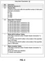
- Figure 2 presents a table to illustrate an example embodiment of early-abort parameters 32 for compression accelerator 22.
- the sample size field specifies when compression accelerator 22 will perform the check to determine whether or not compression is expected to achieve at least a particular amount of size/space savings.
- system software 46 loads a value in the sample size field to select a size from the list consisting of 512 bytes, 1024 bytes, 2048 bytes, and 4096 bytes.
- early-abort circuitry 24 checks as soon as 512, 1024, 2048, or 4096 input bytes have been processed. Also, early-abort circuitry 24 may only check once, when the specified sample size is reached, as described in greater detail below.
- the early-abort threshold field specifies the minimum compression ratio needed to continue with compression.
- the early-abort threshold specifies the amount of size/space savings needed to continue with compression.
- the compression ratio indicates how much smaller the compressed output is, relative to the source data, and it may be computed as input size / output size. For instance, if the compressed output is half the size of the source data, the compression ratio is 50% or 2:1, and if the compressed output is % the size of the source data, the compression ratio is 25% or 4:1. Thus, when expressed as percentages, "smaller" compression ratios reflect more effective compression, and "larger" compression ratios reflect less effective compression.
- early-abort circuitry 24 analyzes a portion of the source data, according to the sample size, and early-abort circuitry 24 computes an estimate of the compression ratio that would be achieved by compression accelerator 22 for that portion of the source data if compression were not to be aborted.
- compression accelerator 22 computes various early-abort values 38 to determine whether or not to take early abort. As illustrated in Figure 1 and described in greater detail below with regard to Figure 3 , those values may include (a) a portion size to indicate how many bytes from the source data are being used to estimate the compression ratio and (b) an estimated compressed size to indicate how big (i.e., how many bytes) the corresponding compressed data would be if compression were not to be aborted. And early-abort circuitry 24 may use that portion size and that estimated compressed size to compute the estimated compression ratio. In addition, early-abort circuitry 24 may perform that analysis of the source data in parallel with the actual compression operations on that source data by compression accelerator 22.
- the early-abort threshold can be set to require a compression ratio of at least 12.5%, at least 25%, at least 37.5%, at least 50%, at least 62.5%, at least 75%, or at least 87.5%, respectively, as described in greater detail below with regard to Figure 3 .
- the early-abort threshold also serves as a flag to enable or disable early-abort functionality.
- system software 46 can set the early-abort threshold field to zero to disable early aborts.
- early-abort parameters 32 also include fields for additional parameters affecting compression, such as one or more parameters pertaining to an analytics engine control and state (EACS) structure.
- EACS analytics engine control and state
- the EACS structure may also be referred to simply as "AECS.”
- the inputs to compression accelerator 22 from system software 46 include (a) the data to be compressed (i.e., the source data) and (b) parameters for controlling the compression process, such as the sample size and early-abort threshold parameters.
- System software 46 may also supply other input parameters, such as a parameter to select a compress version, a parameter pertaining to statistics, etc.
- the outputs from compression accelerator 22 to system software 46 include control and state information.
- the AECS may serve different roles at different times, including a state role and a control role.
- system software 46 uses the AECS to input parameters that do not fit in the descriptor, such as the Huffman tables to be used in the compression.
- the AECS is used to pass information from job to job in the case where a large job is broken into a series of smaller jobs (e.g., to compress a 1-megabyte (MB) file by processing it 64 kilobytes (KB) at a time).
- system software 46 may use the control-size flag to indicate whether the maximum size of the AECS is 64 bytes or 1568 bytes.
- Figure 3 presents a flowchart of an example embodiment of a process to provide for early abort of compression acceleration. That process is described in the context of data processing system 10 from Figure 1 . As shown at block 310, that process may begin with compression accelerator 22 receiving a request for compression acceleration from system software 46. For instance, in an example scenario, system software 46 is using compression accelerator 22 to compress old page 40 in connection with swapping out old page 40.
- compression accelerator 22 In response to the request for compression, compression accelerator 22 checks the parameters from that request to determine whether the request has enabled or disabled early abort. If system software 46 has requested for early abort to be disabled, compression accelerator 22 may generate compressed data (e.g., compressed data 44) based on the complete source data (e.g., old page 40), as shown at block 322. As shown at block 324, compression accelerator 22 may then return results to system software 46. For instance, compression accelerator 22 may set a return code to indicate that compression has been completed without abort. The process may then end.
- compressed data e.g., compressed data 44
- complete source data e.g., old page 40
- compression accelerator 22 may use early-abort circuitry 24 to determine whether to compress the entire source data or to abort the compression process without compressing the entire source data. To make that determination, early-abort circuitry 24 starts generating output tokens, based on the source data, as shown at block 328. Each output token is either a literal or a back reference, as described in greater detail below. As shown at block 330, after generating each output token, early-abort circuitry 24 determines whether the sample size has been reached. If the number of input bytes processed is not greater than or equal to the sample size, the process returns to block 328 and early-abort circuitry 24 continues to generate output tokens until the sample size has been reached.
- the number of bytes to be processed from the source data and the early-abort threshold are controlled by two fields in early-abort parameters 32: the sample-size field and the early-abort threshold field.
- early-abort circuitry 24 computes an estimate of the compressed size for the portion of the source data for which tokens were generated.
- early-abort circuitry 24 computes that estimate by (a) summing or counting the number of literals among the output tokens, (b) multiplying the number of back references by 2, and (c) adding those two results together.
- the estimate of the compressed size is the number of literals plus twice the number of references.
- early-abort circuitry 24 approximates the size of the output by assuming that each literal will take one byte, assuming that each reference will take two bytes, and disregarding the block header.
- the early-abort circuitry may use a different formula to estimate the compressed size for the portion of the source data for which tokens were generated. For instance, if the mode of operation is compression using fixed or canned Huffman codes, which are known at the start of the operation, then the early-abort circuitry can use a more precise bit-level estimate using the symbol bit lengths for each literal or reference. Also, the early-abort circuitry may use a bit-level estimate based on suitable canned code tables that are loaded into the state of the compressor.
- early-abort circuitry 24 looks up the requested threshold size in table of early-abort sizes 34, based on the specified sample size and the specified early-abort threshold. For instance, if the sample size is 512 bytes and the early-abort threshold is 4/8, early-abort circuitry 24 retrieves a threshold size of 256 bytes from table 34.
- early-abort circuitry 24 determines whether (a) the estimated output size (i.e., the estimated size for the portion of the source data for which tokens were generated) is greater than the threshold size. For instance, in the scenario above with a sample size of 512 and an early-abort threshold of 4/8, early-abort circuitry 24 determines whether the estimated output size is greater than 256 bytes. If the estimated output size is greater than the threshold size (or, in another embodiment, greater than or equal to the threshold size), early-abort circuitry 24 aborts compression operations without processing the rest of the source data, as shown at block 342. And as shown at block 324, compression accelerator 22 reports that decision to system software 46. For instance, compression accelerator 22 may set a return code to indicate that compression has been aborted.
- the estimated output size i.e., the estimated size for the portion of the source data for which tokens were generated
- early-abort circuitry 24 proceeds to compress the entire source data and generate compressed data 44, as shown at block 344. And compression accelerator 22 then reports the results to system software 46, as shown at block 324. For instance, compression accelerator 22 may set a return code to indicate that compression has been completed without abort. The process of Figure 3 may then end. Thus, early-abort circuitry 24 causes compression accelerator 22 to abort a compression request if the estimated size for the output file (or a portion of the output file) reflects an unacceptably small amount of compression.
- early-abort circuitry 24 compares the threshold against the input bytes coming to the Deflate compressor, i.e., after the optional zero-compress precompression step has occurred.
- early-abort circuitry may use other types of schedules to perform operations such as determining the estimate of compressed size and determining whether that estimated size is greater than the threshold size.
- early-abort circuitry may be configured to check after every "N" bytes (i.e., after N bytes, after 2N bytes, after 3N bytes, etc.) or to check after every token after crossing the N input-byte threshold.
- the early-abort circuitry may thus check multiple times to determine whether the estimated sizes for different portions of the output file reflect an acceptable amount of compression, and the compression accelerator may complete a compression request only if the early-abort circuitry does not detect an unacceptably small amount of compression in any of those checks.
- compression accelerator 22 is able to abort the compression process after analyzing only a subset of the source data. Compression accelerator 22 is thereby able to produce results more quickly than an accelerator that does not support early abort.
- an advantage of taking an early abort is that, if the compression is not expected to achieve a desired level of compression, the accelerator can notify the software sooner, relative to an accelerator without early-abort circuitry, and thus the latency of the process can be reduced, relative to a process that completes compression before determining whether the compression ratio is acceptable.
- each output token is either a literal or a back reference.
- those tokens are the output of the matching portion of a Deflate compression process. That output can be considered a stream of things, and those things may be referred to as in general as token.
- a token can represent either a literal or a back reference.
- a back reference may also be referred to simply as a "reference" or a "match.”
- a match consists of a length and distance.
- a literal token means to output that literal byte to the output stream.
- a match token means to copy the specified number of bytes from the specified distance back to the output stream.
- the literals and lengths may be encoded to form one Huffman alphabet (which may be referred to as the "literal and length codes” or “LL codes”), and the distances may be encoded to form another (which may be referred to as the "distance codes” or “D codes”).
- the decompressor first decodes an LL symbol. If it is a literal, it outputs the specified byte and looks for another LL symbol. If it is a length, it decodes the next input bits as a D symbol, processes the length/distance, and then processes the next bits as an LL symbol.
- the body of the Deflate block consists of mixed LL and D codes.
- the body can be thought of as being a mixture of either (a) a literal code (i.e., an LL code representing a literal) or (b) a length/distance pair (i.e., an LL code representing a length followed by a D code).
- a literal code i.e., an LL code representing a literal
- a length/distance pair i.e., an LL code representing a length followed by a D code
- compression accelerator 22 provides for early abortion of the compression process, thereby reducing the latency experienced by system software 46 when processing source data.
- early-abort may be used to increase the performance of other types of processes or application, in addition to the page swapping application.
- source data when the source data is encrypted, compressing that encrypted data may not save much space.
- source data may be referred to as relatively incompressible.
- a compression accelerator with early-abort circuitry may be used to quickly determine whether a file or block of source data is relatively incompressible.
- storage applications and communication applications are other types of application that can use early abort to decrease latency and increase system efficiency.
- the technology described herein may be used by any application that is sensitive to compression latency where there is an expectation that a non-trivial number of compression jobs may be for data that is incompressible or minimally compressible.
- a data processing system without early-abort capabilities might compress the complete source data, check the size of the compressed output, and discard the compressed output when it is too large. That approach involves increased latency and decreased system efficiency, relative to an approach that uses early abort.
- the early-abort circuitry allows the system software the adjust aspects of the early-abort process such as how big a portion of the source data is to be used to estimate the compression ratio and the minimum compression ratio desired to continue with compression.
- the system software can adjust the parameters for different types of data sets.
- FIG. 4 is a block diagram of a system 1200 according to one or more embodiments.
- the system 1200 may include one or more processors 1210, 1215, which are coupled to a controller hub 1220.
- the controller hub 1220 includes a graphics memory controller hub (GMCH) 1290 and an Input/Output Hub (IOH) 1250 (which may be on separate chips);
- the GMCH 1290 includes a memory controller to control operations within a coupled memory and a graphics controller to which are coupled memory 1240 and a coprocessor 1245;
- the IOH 1250 couples input/output (I/O) devices 1260 to the GMCH 1290.
- the memory and graphics controllers are integrated within the processor, the memory 1240 and the coprocessor 1245 are coupled directly to the processor 1210, and the controller hub 1220 is in a single chip with the IOH 1250.
- processors 1215 may include one or more processing cores and may be some version of processor 12.
- the memory 1240 may be, for example, dynamic random-access memory (DRAM), phase change memory (PCM), or a combination of the two.
- the controller hub 1220 communicates with the processor(s) 1210, 1215 via a multi-drop bus, such as a frontside bus (FSB), point-to-point interface such as QuickPath Interconnect (QPI), or similar connection 1295.
- a multi-drop bus such as a frontside bus (FSB), point-to-point interface such as QuickPath Interconnect (QPI), or similar connection 1295.
- the coprocessor 1245 is a special-purpose processor, such as, for example, a high-throughput MIC processor, a network or communication processor, a compression engine, graphics processing unit (GPU), a general purpose GPU (GPGPU), an embedded processor, a BW accelerator, or the like.
- controller hub 1220 may include an integrated graphics accelerator.
- the processor 1210 executes instructions that control data processing operations of a general type. Embedded within the instructions may be coprocessor instructions. The processor 1210 recognizes these coprocessor instructions as being of a type that should be executed by the attached coprocessor 1245. Accordingly, the processor 1210 issues these coprocessor instructions (or control signals representing coprocessor instructions) on a coprocessor bus or other interconnect, to coprocessor 1245. Coprocessor(s) 1245 accept and execute the received coprocessor instructions.
- FIG. 5 is a block diagram of a first more specific exemplary system 1300 according to one or more embodiments.
- multiprocessor system 1300 is a point-to-point interconnect system, and includes a first processor 1370 and a second processor 1380 coupled via a point-to-point interconnect 1350.
- processors 1370 and 1380 may be some version of processor 12.
- processors 1370 and 1380 are respectively processors 1210 and 1215, while coprocessor 1338 is coprocessor 1245.
- processors 1370 and 1380 are respectively processor 1210 and coprocessor 1245.
- processor 1380 may be a BW accelerator.
- Processors 1370 and 1380 are shown including integrated memory controller (IMC) units 1372 and 1382, respectively.
- Processor 1370 also includes as part of its bus controller unit's point-to-point (P-P) interfaces 1376 and 1378; similarly, second processor 1380 includes P-P interfaces 1386 and 1388.
- Processors 1370, 1380 may exchange information via a P-P interface 1350 using P-P interface circuits 1378, 1388.
- IMCs 1372 and 1382 couple the processors to respective memories, namely a memory 1332 and a memory 1334, which may be portions of main memory locally attached to the respective processors.
- Processors 1370, 1380 may each exchange information with a chipset 1390 via individual P-P interfaces 1352, 1354 using point to point interface circuits 1376, 1394, 1386, 1398.
- Chipset 1390 may optionally exchange information with the coprocessor 1338 via a high-performance interface 1339.
- the coprocessor 1338 is a special-purpose processor, such as, for example, a high-throughput MIC processor, a network or communication processor, compression engine, graphics processor, GPGPU, embedded processor, or the like.
- a shared cache (not shown) may be included in either processor or outside of both processors, yet connected with the processors via P-P interconnect, such that either or both processors' local cache information may be stored in the shared cache if a processor is placed into a low power mode.
- first bus 1316 may be a Peripheral Component Interconnect (PCI) bus, or a bus such as a PCI Express bus or another third generation I/O interconnect bus, although the scope of the present invention is not so limited.
- PCI Peripheral Component Interconnect
- various I/O devices 1314 may be coupled to first bus 1316, along with a bus bridge 1318 which couples first bus 1316 to a second bus 1320.
- one or more additional processors 1315 such as coprocessors, high-throughput MIC processors, GPGPUs, accelerators (such as, e.g., graphics accelerators or digital signal processing (DSP) units), field programmable gate arrays (FPGAs), or any other processor, are coupled to first bus 1316.
- second bus 1320 may be a low pin count (LPC) bus.
- Various devices may be coupled to a second bus 1320 including, for example, a keyboard and/or mouse 1322, communication devices 1327 and a storage unit 1328 such as a disk drive or other mass storage device which may include instructions/code and data 1330, in one embodiment.
- a storage unit 1328 such as a disk drive or other mass storage device which may include instructions/code and data 1330, in one embodiment.
- an audio I/O 1324 may be coupled to the second bus 1320.
- a system may implement a multi-drop bus or other such architecture.
- Figure 6 is a block diagram of a second more specific exemplary system 1400 in accordance with on one or more embodiments. Certain aspects of Figure 5 have been omitted from Figure 6 in order to avoid obscuring other aspects of Figure 6 .
- FIG 6 illustrates that the processors 1370, 1380 may include integrated memory and I/O control logic ("CL") 1372 and 1382, respectively.
- CL 1372, 1382 include integrated memory controller units and include I/O control logic.
- Figure 6 illustrates that not only are the memories 1332, 1334 coupled to the CL 1372, 1382, but also that I/O devices 1414 are also coupled to the control logic 1372, 1382.
- Legacy I/O devices 1415 are coupled to the chipset 1390.
- FIG. 7 is a block diagram of a system on a chip (SoC) 1500 according to one or more embodiments. Dashed lined boxes are optional features on more advanced SoCs.
- an interconnect unit(s) 1502 is coupled to: an application processor 1510 which includes a set of one or more cores 1102A-N (including constituent cache units 1104A-N) and shared cache unit(s) 1106; a system agent unit 1110; a bus controller unit(s) 1116; an integrated memory controller unit(s) 1114; a set or one or more coprocessors 1520 which may include integrated graphics logic, an image processor, an audio processor, a video processor, and/or a BW accelerator; a static random-access memory (SRAM) unit 1530; a direct memory access (DMA) unit 1532; and a display unit 1540 for coupling to one or more external displays.
- the coprocessor(s) 1520 include a special-purpose processor, such as, for example, a network or communication processor, compression engine
- Such data processing systems may include, without limitation, mainframe computers, mini-computers, supercomputers, high-performance computing systems, computing clusters, distributed computing systems, personal computers (PCs), workstations, servers, client-server systems, portable computers, laptop computers, tablet computers, entertainment devices, audio devices, video devices, audio/video devices (e.g., televisions and set-top boxes), handheld devices, smartphones, telephones, personal digital assistants (PDAs), wearable devices, vehicular processing systems, accelerators, systems on a chip (SoCs), and other devices for processing and/or transmitting information.
- PCs personal computers
- PDAs personal digital assistants
- SoCs systems on a chip
- references to any particular type of data processing system should be understood as encompassing other types of data processing systems, as well.
- a data processing system may also be referred to as an "apparatus.”
- the components of a data processing system may also be referred to as “apparatus.”
- a device may include instructions and other data which, when accessed by a processor, cause the device to perform particular operations.
- instructions or other data which cause a device to perform operations may be referred to in general as “software” or “control logic”.
- Software that is used during a boot process may be referred to as “firmware.”
- Software that is stored in non-volatile memory may also be referred to as “firmware.”
- Software may be organized using any suitable structure or combination of structures. Accordingly, terms like program and module may be used in general to cover a broad range of software constructs, including, without limitation, application programs, subprograms, routines, functions, procedures, drivers, libraries, data structures, processes, microcode, and other types of software components.
- a software module may include more than one component, and those components may cooperate to complete the operations of the module.
- the operations which the software causes a device to perform may include creating an operating context, instantiating a particular data structure, etc.
- embodiments may include software that is implemented using any suitable operating environment and programming language (or combination of operating environments and programming languages).
- program code may be implemented in a compiled language, in an interpreted language, in a procedural language, in an object-oriented language, in assembly language, in machine language, or in any other suitable language.
- a medium which contains data and which allows another component to obtain that data may be referred to as a "machine-accessible medium” or a “machine-readable medium.” Accordingly, embodiments may include machine-readable media containing instructions for performing some or all of the operations described herein. Such media may be referred to in general as “apparatus” and in particular as "program products.”
- software for multiple components may be stored in one machine-readable medium.
- two or more machine-readable media may be used to store the software for one or more components. For instance, instructions for one component may be stored in one medium, and instructions another component may be stored in another medium.
- a portion of the instructions for one component may be stored in one medium, and the rest of the instructions for that component (as well instructions for other components), may be stored in one or more other media.
- software that is described above as residing on a particular device in one embodiment may, in other embodiments, reside on one or more other devices. For instance, in a distributed environment, some software may be stored locally, and some may be stored remotely.
- the machine-readable media may include, without limitation, tangible non-transitory storage components such as magnetic disks, optical disks, magneto-optical disks, dynamic RAM, static RAM, non-volatile RAM (NVRAM), read-only memory (ROM), solid state drives (SSDs), phase change memory (PCM), etc., as well as processors, controllers, and other components that include data storage facilities.
- tangible non-transitory storage components such as magnetic disks, optical disks, magneto-optical disks, dynamic RAM, static RAM, non-volatile RAM (NVRAM), read-only memory (ROM), solid state drives (SSDs), phase change memory (PCM), etc.
- ROM may be used in general to refer to non-volatile memory devices such as erasable programmable ROM (EPROM), electrically erasable programmable ROM (EEPROM), flash ROM, flash memory, etc.
- operations that are described as being performed on one particular device in one embodiment may, in other embodiments, be performed by one or more other devices.
- one or more example processes have been described with regard to particular operations performed in a particular sequence, numerous modifications could be applied to those processes to derive numerous alternative embodiments of the present invention.
- alternative embodiments may include processes that use fewer than all of the disclosed operations, processes that use additional operations, and processes in which the individual operations disclosed herein are combined, subdivided, rearranged, or otherwise altered.
- control logic for implementing the described functionality may be implemented in hardware logic circuitry, such as with an application-specific integrated circuit (ASIC) or with a programmable gate array (PGA).
- ASIC application-specific integrated circuit
- PGA programmable gate array
- control logic may be implemented as microcode in an integrated circuit chip.
- terms such as “circuit” and “circuitry” may be used interchangeably herein.
- logic may be used to refer to analog circuitry, digital circuitry, processor circuitry, microcontroller circuitry, hardware logic circuitry, hard-wired circuitry, programmable circuitry, state machine circuitry, any other type of hardware component, or any suitable combination of hardware components.
- components that are described as being coupled to each other, in communication with each other, responsive to each other, or the like need not be in continuous communication with each other and need not be directly coupled to each other.
- components of the data processing system may be implemented as adapter cards with interfaces (e.g., a connector) for communicating with a bus.
- devices or components may be implemented as embedded controllers, using components such as programmable or non-programmable logic devices or arrays, ASICs, embedded computers, smart cards, and the like.
- bus includes pathways that may be shared by more than two devices, as well as point-to-point pathways.
- terms such as “line,” “pin,” etc. should be understood as referring to a wire, a set of wires, or any other suitable conductor or set of conductors.
- a bus may include one or more serial links, a serial link may include one or more lanes, a lane may be composed of one or more differential signaling pairs, and the changing characteristics of the electricity that those conductors are carrying may be referred to as "signals.”
- processor denotes a hardware component that is capable of executing software.
- a processor may be implemented as a central processing unit (CPU) or as any other suitable type of processing element.
- CPU may include one or more processing cores.
- a processor package may also be referred to as a "processor.”
- a device may include one or more processors.
- inventions may be implemented in data and may be stored on a non-transitory storage medium, which if used by at least one machine, causes the at least one machine to fabricate at least one integrated circuit to perform one or more operations according to the present disclosure. Still further embodiments may be implemented in a computer-readable storage medium including information that, when manufactured into an SoC or other processor, is to configure the SoC or other processor to perform one or more operations according to the present disclosure.
- One or more aspects of at least one embodiment may be implemented by representative instructions, stored on a machine-readable medium, which represent various logic units within the processor, and which, when read by a machine, cause the machine to fabricate logic units to perform the techniques described herein.
- IP cores The instructions representing various logic units may be referred to as "IP cores," and they may be stored on a tangible, machine-readable medium and supplied to various customers or manufacturing facilities to load into the fabrication machines that make the logic units or the processor.
- IP cores One or more aspects of at least one embodiment may include machine-readable media containing instructions or design data which defines structures, circuits, apparatuses, processors and/or system features described herein.
- design data may be formatted in a hardware description language (HDL).
- HDL hardware description language
Landscapes
- Engineering & Computer Science (AREA)
- Theoretical Computer Science (AREA)
- Physics & Mathematics (AREA)
- General Engineering & Computer Science (AREA)
- General Physics & Mathematics (AREA)
- Human Computer Interaction (AREA)
- Software Systems (AREA)
- Compression, Expansion, Code Conversion, And Decoders (AREA)
- Memory System (AREA)
- Advance Control (AREA)
Applications Claiming Priority (2)
| Application Number | Priority Date | Filing Date | Title |
|---|---|---|---|
| US17/304,656 US20220414014A1 (en) | 2021-06-24 | 2021-06-24 | Technology for early abort of compression acceleration |
| EP22159362.7A EP4109278B1 (fr) | 2021-06-24 | 2022-03-01 | Technologie d'interruption précoce d'accélération de compression |
Related Parent Applications (1)
| Application Number | Title | Priority Date | Filing Date |
|---|---|---|---|
| EP22159362.7A Division EP4109278B1 (fr) | 2021-06-24 | 2022-03-01 | Technologie d'interruption précoce d'accélération de compression |
Publications (1)
| Publication Number | Publication Date |
|---|---|
| EP4355047A2 true EP4355047A2 (fr) | 2024-04-17 |
Family
ID=80623869
Family Applications (2)
| Application Number | Title | Priority Date | Filing Date |
|---|---|---|---|
| EP24157172.8A Pending EP4355047A2 (fr) | 2021-06-24 | 2022-03-01 | Technologie pour avortement précoce d'accélération de compression |
| EP22159362.7A Active EP4109278B1 (fr) | 2021-06-24 | 2022-03-01 | Technologie d'interruption précoce d'accélération de compression |
Family Applications After (1)
| Application Number | Title | Priority Date | Filing Date |
|---|---|---|---|
| EP22159362.7A Active EP4109278B1 (fr) | 2021-06-24 | 2022-03-01 | Technologie d'interruption précoce d'accélération de compression |
Country Status (7)
| Country | Link |
|---|---|
| US (1) | US20220414014A1 (fr) |
| EP (2) | EP4355047A2 (fr) |
| JP (1) | JP2023004848A (fr) |
| KR (1) | KR20230001017A (fr) |
| CN (1) | CN115525212A (fr) |
| TW (1) | TW202324109A (fr) |
| WO (1) | WO2022271224A1 (fr) |
Family Cites Families (12)
| Publication number | Priority date | Publication date | Assignee | Title |
|---|---|---|---|---|
| US7024512B1 (en) * | 1998-02-10 | 2006-04-04 | International Business Machines Corporation | Compression store free-space management |
| US6961473B1 (en) * | 2000-10-23 | 2005-11-01 | International Business Machines Corporation | Faster transforms using early aborts and precision refinements |
| US9940230B2 (en) * | 2010-10-22 | 2018-04-10 | Cnex Labs, Inc. | Compression and decompression of data at high speed in solid state storage |
| US9158686B2 (en) * | 2012-03-30 | 2015-10-13 | Altera Corporation | Processing system and method including data compression API |
| US9531403B2 (en) * | 2013-09-25 | 2016-12-27 | Nec Corporation | Adaptive compression supporting output size thresholds |
| JP2015115652A (ja) * | 2013-12-09 | 2015-06-22 | キヤノン株式会社 | 情報処理装置、情報処理方法及びプログラム |
| US9600317B2 (en) * | 2014-04-16 | 2017-03-21 | Vmware, Inc. | Page compressibility checker |
| US9753666B2 (en) * | 2015-03-27 | 2017-09-05 | Intel Corporation | Efficient data compression for solid-state memory |
| US10942844B2 (en) * | 2016-06-10 | 2021-03-09 | Apple Inc. | Reserved memory in memory management system |
| US10002081B2 (en) * | 2016-07-05 | 2018-06-19 | Intel Corporation | Apparatus for hardware implementation of heterogeneous decompression processing |
| US10579591B1 (en) * | 2016-12-20 | 2020-03-03 | Amazon Technologies, Inc. | Incremental block compression |
| US11303296B2 (en) * | 2018-06-26 | 2022-04-12 | International Business Machines Corporation | Hardware accelerated compression of instrumentation data |
-
2021
- 2021-06-24 US US17/304,656 patent/US20220414014A1/en active Pending
-
2022
- 2022-03-01 JP JP2022030743A patent/JP2023004848A/ja active Pending
- 2022-03-01 EP EP24157172.8A patent/EP4355047A2/fr active Pending
- 2022-03-01 EP EP22159362.7A patent/EP4109278B1/fr active Active
- 2022-03-14 WO PCT/US2022/020102 patent/WO2022271224A1/fr unknown
- 2022-03-16 TW TW111109596A patent/TW202324109A/zh unknown
- 2022-03-30 KR KR1020220039670A patent/KR20230001017A/ko unknown
- 2022-05-09 CN CN202210496422.7A patent/CN115525212A/zh active Pending
Also Published As
| Publication number | Publication date |
|---|---|
| US20220414014A1 (en) | 2022-12-29 |
| EP4109278A1 (fr) | 2022-12-28 |
| EP4109278B1 (fr) | 2024-02-14 |
| JP2023004848A (ja) | 2023-01-17 |
| TW202324109A (zh) | 2023-06-16 |
| WO2022271224A1 (fr) | 2022-12-29 |
| CN115525212A (zh) | 2022-12-27 |
| KR20230001017A (ko) | 2023-01-03 |
Similar Documents
| Publication | Publication Date | Title |
|---|---|---|
| US7849241B2 (en) | Memory compression method and apparatus for heterogeneous processor architectures in an information handling system | |
| US8001294B2 (en) | Methods and apparatus for providing a compressed network in a multi-processing system | |
| US20190042925A1 (en) | Methods and arrangements to manage memory in cascaded neural networks | |
| US20210279074A1 (en) | Overflow detection and correction in state machine engines | |
| CN111240743B (zh) | 人工智能集成电路 | |
| CN106648955B (zh) | 压缩方法及相关装置 | |
| TW201730752A (zh) | 用於有狀態壓縮和解壓縮操作的硬體加速器及方法 | |
| KR20230142355A (ko) | 데이터베이스 스캔 가속을 위한 시스템 및 방법 | |
| US20140047199A1 (en) | Memory-Link Compression for Graphic Processor Unit | |
| EP4355047A2 (fr) | Technologie pour avortement précoce d'accélération de compression | |
| US20210109759A1 (en) | Pipelined method to improve backup and restore performance | |
| US11456972B2 (en) | Methods and arrangements to accelerate array searches | |
| CN116893779A (zh) | 用于数据库扫描加速的系统和方法 | |
| US10133685B2 (en) | Bus interface device that merges data request signals, semiconductor integrated circuit device including the same, and method of operating the same | |
| US10848179B1 (en) | Performance optimization and support compatibility of data compression with hardware accelerator | |
| US11093283B2 (en) | System and method of dynamically allocating compression jobs | |
| KR20210075007A (ko) | 인공지능 프로세서를 위한 캐시 | |
| US11915138B2 (en) | Method and device for reducing a size of a neural network model | |
| US20220391110A1 (en) | Adaptive compression for accelerator devices | |
| US10840943B1 (en) | System and method of data compression between backup server and storage | |
| CN111382853A (zh) | 数据处理装置、方法、芯片及电子设备 | |
| US20220368348A1 (en) | Universal decompression for accelerator devices | |
| CN111382855B (zh) | 数据处理装置、方法、芯片及电子设备 | |
| US20230350720A1 (en) | Chaining Services in an Accelerator Device | |
| CN113033791A (zh) | 用于保序的计算装置、集成电路装置、板卡及保序方法 |
Legal Events
| Date | Code | Title | Description |
|---|---|---|---|
| PUAI | Public reference made under article 153(3) epc to a published international application that has entered the european phase |
Free format text: ORIGINAL CODE: 0009012 |
|
| STAA | Information on the status of an ep patent application or granted ep patent |
Free format text: STATUS: THE APPLICATION HAS BEEN PUBLISHED |
|
| AC | Divisional application: reference to earlier application |
Ref document number: 4109278 Country of ref document: EP Kind code of ref document: P |
|
| AK | Designated contracting states |
Kind code of ref document: A2 Designated state(s): AL AT BE BG CH CY CZ DE DK EE ES FI FR GB GR HR HU IE IS IT LI LT LU LV MC MK MT NL NO PL PT RO RS SE SI SK SM TR |