EP4354049A1 - Compressor assembly, air conditioner outdoor unit, and air conditioning system - Google Patents
Compressor assembly, air conditioner outdoor unit, and air conditioning system Download PDFInfo
- Publication number
- EP4354049A1 EP4354049A1 EP22885426.1A EP22885426A EP4354049A1 EP 4354049 A1 EP4354049 A1 EP 4354049A1 EP 22885426 A EP22885426 A EP 22885426A EP 4354049 A1 EP4354049 A1 EP 4354049A1
- Authority
- EP
- European Patent Office
- Prior art keywords
- gas
- return hole
- oil
- oil return
- pipe
- Prior art date
- Legal status (The legal status is an assumption and is not a legal conclusion. Google has not performed a legal analysis and makes no representation as to the accuracy of the status listed.)
- Withdrawn
Links
Images




Classifications
-
- F—MECHANICAL ENGINEERING; LIGHTING; HEATING; WEAPONS; BLASTING
- F25—REFRIGERATION OR COOLING; COMBINED HEATING AND REFRIGERATION SYSTEMS; HEAT PUMP SYSTEMS; MANUFACTURE OR STORAGE OF ICE; LIQUEFACTION SOLIDIFICATION OF GASES
- F25B—REFRIGERATION MACHINES, PLANTS OR SYSTEMS; COMBINED HEATING AND REFRIGERATION SYSTEMS; HEAT PUMP SYSTEMS
- F25B31/00—Compressor arrangements
- F25B31/002—Lubrication
- F25B31/004—Lubrication oil recirculating arrangements
-
- F—MECHANICAL ENGINEERING; LIGHTING; HEATING; WEAPONS; BLASTING
- F04—POSITIVE - DISPLACEMENT MACHINES FOR LIQUIDS; PUMPS FOR LIQUIDS OR ELASTIC FLUIDS
- F04B—POSITIVE-DISPLACEMENT MACHINES FOR LIQUIDS; PUMPS
- F04B39/00—Component parts, details, or accessories, of pumps or pumping systems specially adapted for elastic fluids, not otherwise provided for in, or of interest apart from, groups F04B25/00 - F04B37/00
- F04B39/02—Lubrication
- F04B39/0284—Constructional details, e.g. reservoirs in the casing
-
- F—MECHANICAL ENGINEERING; LIGHTING; HEATING; WEAPONS; BLASTING
- F04—POSITIVE - DISPLACEMENT MACHINES FOR LIQUIDS; PUMPS FOR LIQUIDS OR ELASTIC FLUIDS
- F04B—POSITIVE-DISPLACEMENT MACHINES FOR LIQUIDS; PUMPS
- F04B39/00—Component parts, details, or accessories, of pumps or pumping systems specially adapted for elastic fluids, not otherwise provided for in, or of interest apart from, groups F04B25/00 - F04B37/00
- F04B39/04—Measures to avoid lubricant contaminating the pumped fluid
-
- F—MECHANICAL ENGINEERING; LIGHTING; HEATING; WEAPONS; BLASTING
- F04—POSITIVE - DISPLACEMENT MACHINES FOR LIQUIDS; PUMPS FOR LIQUIDS OR ELASTIC FLUIDS
- F04B—POSITIVE-DISPLACEMENT MACHINES FOR LIQUIDS; PUMPS
- F04B39/00—Component parts, details, or accessories, of pumps or pumping systems specially adapted for elastic fluids, not otherwise provided for in, or of interest apart from, groups F04B25/00 - F04B37/00
- F04B39/16—Filtration; Moisture separation
-
- F—MECHANICAL ENGINEERING; LIGHTING; HEATING; WEAPONS; BLASTING
- F24—HEATING; RANGES; VENTILATING
- F24F—AIR-CONDITIONING; AIR-HUMIDIFICATION; VENTILATION; USE OF AIR CURRENTS FOR SCREENING
- F24F1/00—Room units for air-conditioning, e.g. separate or self-contained units or units receiving primary air from a central station
- F24F1/0003—Room units for air-conditioning, e.g. separate or self-contained units or units receiving primary air from a central station characterised by a split arrangement, wherein parts of the air-conditioning system, e.g. evaporator and condenser, are in separately located units
-
- F—MECHANICAL ENGINEERING; LIGHTING; HEATING; WEAPONS; BLASTING
- F24—HEATING; RANGES; VENTILATING
- F24F—AIR-CONDITIONING; AIR-HUMIDIFICATION; VENTILATION; USE OF AIR CURRENTS FOR SCREENING
- F24F1/00—Room units for air-conditioning, e.g. separate or self-contained units or units receiving primary air from a central station
- F24F1/06—Separate outdoor units, e.g. outdoor unit to be linked to a separate room comprising a compressor and a heat exchanger
- F24F1/08—Compressors specially adapted for separate outdoor units
-
- F—MECHANICAL ENGINEERING; LIGHTING; HEATING; WEAPONS; BLASTING
- F25—REFRIGERATION OR COOLING; COMBINED HEATING AND REFRIGERATION SYSTEMS; HEAT PUMP SYSTEMS; MANUFACTURE OR STORAGE OF ICE; LIQUEFACTION SOLIDIFICATION OF GASES
- F25B—REFRIGERATION MACHINES, PLANTS OR SYSTEMS; COMBINED HEATING AND REFRIGERATION SYSTEMS; HEAT PUMP SYSTEMS
- F25B13/00—Compression machines, plants or systems, with reversible cycle
-
- F—MECHANICAL ENGINEERING; LIGHTING; HEATING; WEAPONS; BLASTING
- F25—REFRIGERATION OR COOLING; COMBINED HEATING AND REFRIGERATION SYSTEMS; HEAT PUMP SYSTEMS; MANUFACTURE OR STORAGE OF ICE; LIQUEFACTION SOLIDIFICATION OF GASES
- F25B—REFRIGERATION MACHINES, PLANTS OR SYSTEMS; COMBINED HEATING AND REFRIGERATION SYSTEMS; HEAT PUMP SYSTEMS
- F25B41/00—Fluid-circulation arrangements
- F25B41/20—Disposition of valves, e.g. of on-off valves or flow control valves
-
- F—MECHANICAL ENGINEERING; LIGHTING; HEATING; WEAPONS; BLASTING
- F25—REFRIGERATION OR COOLING; COMBINED HEATING AND REFRIGERATION SYSTEMS; HEAT PUMP SYSTEMS; MANUFACTURE OR STORAGE OF ICE; LIQUEFACTION SOLIDIFICATION OF GASES
- F25B—REFRIGERATION MACHINES, PLANTS OR SYSTEMS; COMBINED HEATING AND REFRIGERATION SYSTEMS; HEAT PUMP SYSTEMS
- F25B43/00—Arrangements for separating or purifying gases or liquids; Arrangements for vaporising the residuum of liquid refrigerant, e.g. by heat
-
- F—MECHANICAL ENGINEERING; LIGHTING; HEATING; WEAPONS; BLASTING
- F25—REFRIGERATION OR COOLING; COMBINED HEATING AND REFRIGERATION SYSTEMS; HEAT PUMP SYSTEMS; MANUFACTURE OR STORAGE OF ICE; LIQUEFACTION SOLIDIFICATION OF GASES
- F25B—REFRIGERATION MACHINES, PLANTS OR SYSTEMS; COMBINED HEATING AND REFRIGERATION SYSTEMS; HEAT PUMP SYSTEMS
- F25B43/00—Arrangements for separating or purifying gases or liquids; Arrangements for vaporising the residuum of liquid refrigerant, e.g. by heat
- F25B43/006—Accumulators
-
- F—MECHANICAL ENGINEERING; LIGHTING; HEATING; WEAPONS; BLASTING
- F25—REFRIGERATION OR COOLING; COMBINED HEATING AND REFRIGERATION SYSTEMS; HEAT PUMP SYSTEMS; MANUFACTURE OR STORAGE OF ICE; LIQUEFACTION SOLIDIFICATION OF GASES
- F25B—REFRIGERATION MACHINES, PLANTS OR SYSTEMS; COMBINED HEATING AND REFRIGERATION SYSTEMS; HEAT PUMP SYSTEMS
- F25B43/00—Arrangements for separating or purifying gases or liquids; Arrangements for vaporising the residuum of liquid refrigerant, e.g. by heat
- F25B43/02—Arrangements for separating or purifying gases or liquids; Arrangements for vaporising the residuum of liquid refrigerant, e.g. by heat for separating lubricants from the refrigerant
-
- F—MECHANICAL ENGINEERING; LIGHTING; HEATING; WEAPONS; BLASTING
- F25—REFRIGERATION OR COOLING; COMBINED HEATING AND REFRIGERATION SYSTEMS; HEAT PUMP SYSTEMS; MANUFACTURE OR STORAGE OF ICE; LIQUEFACTION SOLIDIFICATION OF GASES
- F25B—REFRIGERATION MACHINES, PLANTS OR SYSTEMS; COMBINED HEATING AND REFRIGERATION SYSTEMS; HEAT PUMP SYSTEMS
- F25B2400/00—Component parts or details not otherwise provided for in this subclass
- F25B2400/07—Details of compressors or related parts
- F25B2400/075—Details of compressors or related parts with parallel compressors
Definitions
- This application relates to the field of air conditioning equipment, and more particularly to a compressor assembly, an air conditioner outdoor unit, and an air conditioning system.
- multi-unit heat pump air conditioning systems have increasing capacity.
- the multi-unit heat pump air conditioning systems also face problems such as insufficient volume for gas separation and difficulty in recovering refrigeration oil, which limit the development of the multi-unit heat pump air conditioning systems.
- parallel connection is adopted for gas separation to expand the capacity of the air conditioning system, which solves the problem of insufficient gas separation volume, but leads to poor reliability of compressor operation.
- the present invention aims to solve at least one of the technical problems existing in the related art to a certain extent.
- embodiments of the present invention propose a compressor assembly to improve operational reliability of a compressor.
- Embodiments of the present invention also propose an air conditioner outdoor unit to improve operational reliability of the air conditioner outdoor unit.
- Embodiments of the present invention also propose an air conditioning system to improve operational reliability of the air conditioning system.
- the compressor assembly comprises: a first compressor comprising a first exhaust port and a first gas return port; a second compressor comprising a second exhaust port and a second gas return port; a first oil separator comprising a first oil outlet and a first oil separator inlet, the first oil separator inlet being communicated to the first exhaust port; a second oil separator comprising a second oil outlet and a second oil separator inlet, the second oil separator inlet being communicated to the second exhaust port; a first gas-liquid separator comprising a first separation chamber, a first gas separator inlet, a first oil return hole and a first gas separator outlet, wherein the first gas separator inlet, the first oil return hole and the first gas separator outlet are communicated to the first separation chamber, and wherein the first oil outlet is communicated to the first gas separator inlet, and the first gas separator outlet and the first oil return hole are each communicated to the first gas return port; a second gas-liquid separator comprising a
- the compressor assembly according to embodiments of the present invention has advantages such as high operational reliability.
- the first gas-liquid separator comprises: a first cylinder, the first separation chamber being defined in the first cylinder; and a first gas outlet pipe, a portion of the first gas outlet pipe extending into the first separation chamber, the first oil return hole being in the portion of the first gas outlet pipe, and the first gas separator outlet being in an other portion of the first gas outlet pipe.
- the second gas-liquid separator comprises: a second cylinder, the second separation chamber being defined in the second cylinder; and a second gas outlet pipe, a portion of the second gas outlet pipe extending into the second separation chamber, the second oil return hole being in the portion of the second gas outlet pipe, and the second gas separator outlet being in an other portion of the second gas outlet pipe.
- the end of the liquid balance pipe is above the first oil return hole or at a same height as the first oil return hole; and the other end of the liquid balance pipe is above the second oil return hole or at a same height as the second oil return hole.
- the portion of the first gas outlet pipe comprises a third oil return hole communicated to the first separation chamber
- the portion of the second gas outlet pipe comprises a fourth oil return hole communicated to the second separation chamber.
- the third oil return hole is above the first oil return hole or at a same height as the first oil return hole
- the fourth oil return hole is above the second oil return hole or at a same height as the second oil return hole.
- the end of the liquid balance pipe is between the first oil return hole and the third oil return hole in an up-down direction, and the other end of the liquid balance pipe is between the second oil return hole and the fourth oil return hole in the up-down direction.
- the end of the gas balance pipe is above the third oil return hole or at a same height as the third oil return hole, and the other end of the gas balance pipe is above the fourth oil return hole or at a same height as the fourth oil return hole.
- the third oil return hole is between the end of the gas balance pipe and the end of the liquid balance pipe in an up-down direction; and the fourth oil return hole is between the other end of the gas balance pipe and the other end of the liquid balance pipe in the up-down direction.
- the first oil return hole and the second oil return hole are at a same height; and/or a bottom wall surface of the first separation chamber and a bottom wall surface of the second separation chamber are at a same height, the end of the liquid balance pipe and the other end of the liquid balance pipe are at a same height, and the end of the gas balance pipe and the other end of the gas balance pipe are at a same height.
- the third oil return hole and the fourth oil return hole are at a same height.
- the portion of the first gas outlet pipe and the portion of the second gas outlet pipe each comprise a U-shaped portion.
- the U-shaped portion comprises: a first segment and a second segment, the first segment and the second segment extending in an up-down direction; and an intermediate segment, comprising an end connected to a lower end of the first segment, and an other end connected to a lower end of the second segment.
- the first oil return hole is in the intermediate segment of the first gas outlet pipe;
- the third oil return hole is in the first segment of the first gas outlet pipe;
- the second oil return hole is in the intermediate segment of the second gas outlet pipe;
- the fourth oil return hole is in the first segment of the second gas outlet pipe.
- the air conditioner outdoor unit comprises: a four-way valve, comprising a first interface, a second interface, a third interface, and a fourth interface; an outdoor heat exchanger, a first port of the outdoor heat exchanger being connected to the first interface; and the compressor assembly according to any one of the above embodiments.
- the first oil separator comprises a first oil separator outlet
- the second oil separator comprises a second oil separator outlet; the first oil separator outlet and the second oil separator outlet are each connected to the second interface; and the first gas separator inlet and the second gas separator inlet are each connected to the fourth interface.
- the air conditioner outdoor unit according to embodiments of the present invention has advantages such as high operational reliability.
- the air conditioning system comprises: the air conditioner outdoor unit according to any one of the above embodiments; and an air conditioner indoor unit comprising an indoor heat exchanger.
- a second port of the outdoor heat exchanger is connected to a first port of the indoor heat exchanger, and a second port of the indoor heat exchanger is connected to the third interface.
- the air conditioning system according to embodiments of the present invention has advantages such as high operational reliability.
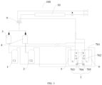
- the compressor assembly As shown in FIGS. 1 to 3 , the compressor assembly according to embodiments of the present invention comprise a first compressor 1, a second compressor 2, a first oil separator 3, a second oil separator 4, a first gas-liquid separator 5, a second gas-liquid separator 6, a liquid balance pipe 7, and a gas balance pipe 8.
- the first compressor 1 has a first exhaust port 101 and a first gas return port 102.
- the second compressor 2 has a second exhaust port 201 and a second gas return port 202.
- the first oil separator 3 has a first oil outlet 302 and a first oil separator inlet 301 that is communicated to the first exhaust port 101.
- the second oil separator 4 has a second oil outlet 402 and a second oil separator inlet 401 that is communicated to the second exhaust port 201.
- the first gas-liquid separator 5 has a first separation chamber 5011 and comprises a first gas separator inlet 5031, a first oil return hole 5022 and a first gas separator outlet 5021, all of which are communicated to the first separation chamber 5011.
- the second gas-liquid separator 6 has a second separation chamber 6011 and comprises a second gas separator inlet 6031, a second oil return hole 6022 and a second gas separator outlet 6021, all of which are communicated to the second separation chamber 6011.
- the first oil outlet 302 is communicated to the first gas separator inlet 5031, and the second oil outlet 402 is communicated to the second gas separator inlet 6031.
- the first gas separator outlet 5021 and the first oil return hole 5022 are each communicated to the first gas return port 102.
- the second gas separator outlet 6021 and the second oil return hole 6022 are each communicated to the second gas return port 202.
- the gas balance pipe 8 is above the liquid balance pipe 7. It can be understood by those skilled in the art that the gas balance pipe 8 being above the liquid balance pipe 7 means that when the first gas-liquid separator 5 and the second gas-liquid separator 6 are in use, the gas balance pipe 8 is above the liquid balance pipe 7.
- the liquid balance pipe 7 and one end of the gas balance pipe 8 are both communicated to the first separation chamber 5011, while the other end of the liquid balance pipe 7 and the other end of the gas balance pipe 8 are both communicated to the second separation chamber 6011.
- the liquid balance pipe 7 has a first end 701 and a second end 702 opposite to each other in its length direction
- the gas balance pipe 8 has a third end 801 and a fourth end 802 opposite to each other in its length direction
- the first end 701 and the third end 801 are each communicated to the first separation chamber 5011
- the second end 702 and the fourth end 802 are each communicated to the second separation chamber 6011.
- liquid balance pipe 7 and the gas balance pipe 8 can achieve connection between the first separation chamber 5011 and the second separation chamber 6011, thereby achieving liquid balance and gas balance between the first separation chamber 5011 and the second separation chamber 6011.
- refrigerant vapor containing refrigeration oil (first oil-containing refrigerant vapor) flowing out of the first exhaust port 101 of the first compressor 1 enters the first oil separator 3 through the first oil separator inlet 301, and the first oil-containing refrigerant vapor is separated into first refrigerant vapor and first refrigeration oil in the first oil separator 3.
- the first refrigeration oil enters the first separation chamber 5011 of the first gas-liquid separator 5 through the first oil outlet 302 and the first gas separator inlet 5031, and the first refrigerant vapor enters an indoor heat exchanger for heat exchange.
- refrigerant vapor containing refrigeration oil (second oil-containing refrigerant vapor) flowing out of the second exhaust port 201 of the second compressor 2 enters the second oil separator 4 through the second oil separator inlet 401, and the second oil-containing refrigerant vapor is separated into second refrigerant vapor and second refrigeration oil in the second oil separator 4.
- the second refrigeration oil enters the second separation chamber 6011 of the second gas-liquid separator 6 through the second oil outlet 402 and the second gas separator inlet 6031, and the second refrigerant vapor enters the indoor heat exchanger for heat exchange.
- a part of the refrigerant (a third refrigerant), which flows out of the indoor heat exchanger and needs to return to the first compressor 1 and the second compressor 2, enters the first separation chamber 5011 of the first gas-liquid separator 5 through the first gas separator inlet 5031; and another part of the refrigerant (a fourth refrigerant), which flows out of the indoor heat exchanger and needs to return to the first compressor 1 and the second compressor 2, enters the second separation chamber 6011 of the second gas-liquid separator 6 through the second gas separator inlet 6031.
- a third refrigerant which flows out of the indoor heat exchanger and needs to return to the first compressor 1 and the second compressor 2 enters the first separation chamber 5011 of the first gas-liquid separator 5 through the first gas separator inlet 5031
- a fourth refrigerant which flows out of the indoor heat exchanger and needs to return to the first compressor 1 and the second compressor 2 enters the second separation chamber 6011 of the second gas-liquid separator 6 through the second gas separator inlet 6031
- the refrigeration oil in the first separation chamber 5011 can return, along with the refrigerant vapor, to the first compressor 1 through the first oil return hole 5022, the first gas separator outlet 5021 and the first gas return port 102; in a suction process of the second compressor 2 (the third refrigerant and the fourth refrigerant), the refrigeration oil in the second separation chamber 6011 can return, along with the refrigerant vapor, to the second compressor 2 through the second oil return hole 6022, the second gas separator outlet 6021 and the second gas return port 202.
- recovery of refrigeration oil in the first compressor 1 and the second compressor 2 can be realized.
- the first separation chamber 5011 of the first gas-liquid separator 5 and the second separation chamber 6011 of the second gas-liquid separator 6 are connected through the liquid balance pipe 7 and the gas balance pipe 8, it can be ensured that the first separation chamber 5011 of the first gas-liquid separator 5 and the second separation chamber 6011 of the second gas-liquid separator 6 both have refrigeration oil and refrigerant therein, which can reduce or even avoid a large refrigerant distribution deviation (i.e., there is a large amount of refrigerant at the gas separator inlet of the gas-liquid separator corresponding to the large capacity compressor, while there is very little refrigerant at the gas separator inlet of the gas-liquid separator corresponding to the small capacity compressor) at the first gas separator inlet 5031 of the first gas-liquid separator 5 and the second gas separator inlet 6031 of the second gas-liquid separator 6 caused by different capacities of the first compressor 1 and the second compressor 2.
- the problem of insufficient return oil or even inability to return oil for small capacity compressors due to the different capacities of the first compressor 1 and the second compressor 2 can be relieved or even avoided, thereby preventing compressor wear for lack of lubrication caused by untimely oil return or inability to return oil, and greatly improving the reliability of the compressor assembly.
- the compressor assembly according to embodiments of the present invention has advantages such as high reliability.
- each compressor according to embodiments of the present invention has its corresponding oil separator and gas-liquid separator, allowing each compressor to form a relatively independent refrigeration oil circulation system.
- the compressor assembly comprises a first pipe 11, a second pipe 12, a third pipe 13, a fourth pipe 14, a fifth pipe 15, and a sixth pipe 16.
- the first exhaust port 101 is connected to the first oil separator inlet 301 through the first pipe 11, and the second exhaust port 201 is connected to the second oil separator inlet 401 through the second pipe 12.
- the first oil outlet 302 is communicated to the first gas separator inlet 5031 through the fifth pipe 15, and the second oil outlet 402 is communicated to the second gas separator inlet 6031 through the sixth pipe 16.
- the first gas separator outlet 5021 is connected to the first return gas outlet 102 through the third pipe 13, and the second gas separator outlet 6021 is connected to the second return gas outlet 202 through the fourth pipe 14.
- the first gas-liquid separator 5 comprises a first cylinder 501 and a first gas outlet pipe 502.
- the first separation chamber 5011 is defined in first cylinder 501, and a part of the first gas outlet pipe 502 extends into the first separation chamber 5011.
- the first oil return hole 5022 is in the part of the first gas outlet pipe 502, and the first gas separator outlet 5021 is in another part of the first gas outlet pipe 502.
- the first gas outlet pipe 502 comprises a first portion and a second portion, the first portion extends into the first separation chamber 5011, and the second portion is outside the first separation chamber 5011.
- the first oil return hole 5022 is in the first portion of the first gas outlet pipe 502, and the first gas separator outlet 5021 is in the second portion of the first gas outlet pipe 502.
- the second gas-liquid separator 6 comprises a second cylinder 601 and a second gas outlet pipe 602.
- the second separation chamber 6011 is defined in the second cylinder 601, and a part of the second gas outlet pipe 602 extends into the second separation chamber 6011.
- the second oil return hole 6022 is in the part of the second gas outlet pipe 602, and the second gas separator outlet 6021 is in another part of the second gas outlet pipe 602.
- the second gas outlet pipe 602 comprises a first portion and a second portion, the first portion extends into the second separation chamber 6011, and the second portion is outside the second separation chamber 6011.
- the second oil return hole 6022 is in the first portion of the second gas outlet pipe 602, and the second gas separator outlet 6021 is in the second portion of the second gas outlet pipe 602.
- One end of the liquid balance pipe 7 is above the first oil return hole 5022 or at a same height as the first oil return hole 5022; the other end of the liquid balance pipe 7 is above the second oil return hole 6022 or at a same height as the second oil return hole 6022.
- one end of the liquid balance pipe 7 is above the first oil return hole 5022 or at the same height as the first oil return hole 5022, and the other end of the liquid balance pipe 7 is above the second oil return hole 6022 or at the same height as the second oil return hole 6022.
- a bottom wall surface of the first separation chamber 5011 and a bottom wall surface of the second separation chamber 6011 are at the same height.
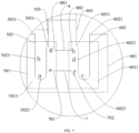
- a distance between the first end 701 (e) of the liquid balance pipe 7 and the bottom wall surface of the first separation chamber 5011 is denoted as L1; a distance between the first oil return hole 5022 (a) and the bottom wall surface of the first separation chamber 5011 is denoted as L2; a distance between the second end 702 (f) of the liquid balance pipe 7 and the bottom wall surface of the second separation chamber 6011 is denoted as L3; and a distance between the second oil return hole 6022 (c) and the bottom wall surface of the second separation chamber 6011 is L4, in which L1 ⁇ L2 and L3 ⁇ L4.
- the refrigeration oil in the first separation chamber 5011 can enter the second separation chamber 6011 through the liquid balance pipe 7 only when a liquid level of the refrigeration oil in the first separation chamber 5011 is not lower than the first oil return hole 5022; the refrigeration oil in the second separation chamber 6011 can enter the first separation chamber 5011 through the liquid balance pipe 7 only when a liquid level of the refrigeration oil in the second separation chamber 6011 is not lower than the second oil return hole 6022.
- the refrigeration oil in the first separation chamber 5011 first return to the first compressor 1, and only on the premise that the first compressor 1 has returned oil, the refrigeration oil in the first separation chamber 5011 can enter the second separation chamber 6011 to provide refrigeration oil for the second compressor 2; and the refrigeration oil in the second separation chamber 6011 first return to the second compressor 2, and only on the premise that the second compressor 2 has returned oil, the refrigeration oil in the second separation chamber 6011 can enter the first separation chamber 5011 to provide refrigeration oil for the first compressor 1.
- the reliability of the compressor assembly can be further enhanced.
- the first gas-liquid separator 5 comprises a first gas inlet pipe 503, and a part of the first gas inlet pipe 503 extends into the first separation chamber 5011, the first gas separator inlet 5031 being in the part of the first gas inlet pipe 503.
- the second gas-liquid separator 6 comprises a second gas inlet pipe 603 that extends into the second separation chamber 6011. A part of the second gas inlet pipe 603 extends into the second separation chamber 6011, and the second gas separator inlet 6031 is in the part of the second gas inlet pipe 603.
- the first gas inlet pipe 503 and the first oil outlet 302 are connected through the fifth pipe 15, and the second gas inlet pipe 603 and the second oil outlet 402 are connected through the sixth pipe 16.
- one end of the liquid balance pipe 7 extends into an interior of the first cylinder 501, so that one end of the liquid balance pipe 7 is communicated to the first separation chamber 5011; the other end of the liquid balance pipe 7 extends into an interior of the second cylinder 601, so that the other end of the liquid balance pipe 7 is communicated to the second separation chamber 6011.
- the first end 701 of the liquid balance pipe 7 extends into the interior of the first cylinder 501, and the second end 702 of the liquid balance pipe 7 extends into the interior of the second cylinder 601.
- the first oil return hole 5022 and the second oil return hole 6022 are at the same height.
- each of the liquid balance pipe 7 and the gas balance pipe 8 is a straight pipe.
- the liquid balance pipe 7 is a straight pipe
- a connection port between the liquid balance pipe 7 and the first gas-liquid separator 5 is denoted as e
- a connection port between the liquid balance pipe 7 and the second gas-liquid separator 6 is denoted as f, in which e and f are at the same height.
- the first end 701 of the liquid balance pipe 7 and the second end 702 of the liquid balance pipe 7 are both at the same height as the connection port e (the connection port f).
- At least one of the liquid balance pipe 7 and the gas balance pipe 8 is a bent pipe.
- the liquid balance pipe 7 comprises a first pipe segment 703, a second pipe segment 704, and a third pipe segment 705.
- the second pipe segment 704 is horizontally arranged, and the first and third pipe segments 703 and 705 are both obliquely arranged.
- One end of the second pipe segment 704 is connected to a lower end of the first pipe segment 703, and the other end of the second pipe segment 704 is connected to a lower end of the third pipe segment 705.
- the two ends of the second pipe segment 704 are connected to the first gas-liquid separator 5 and the second gas-liquid separator 6, respectively.
- a connection port between the second pipe segment 704 and the first gas-liquid separator 5 is denoted as e2; and a connection port between the second pipe segment 704 and the second gas-liquid separator 6 is denoted as f2.
- the first pipe segment 703 extends into the first separation chamber 5011, and the third pipe segment 705 extends into the second separation chamber 6011.
- An end e1 of the first pipe segment 703 away from the second pipe segment 704 is the first end 701 of the liquid balance pipe 7, and an end f1 of the third pipe segment 705 away from the second pipe segment 704 is the second end 702 of the liquid balance pipe 7.
- the connection port e2 and the end e1 are at different heights
- the connection port f2 and the end f1 are at different heights.
- a part of the first gas outlet pipe 502 has a third oil return hole 5023 communicated to the first separation chamber 5011, and a part of the second gas outlet pipe 602 has a fourth oil return hole 6023 communicated to the second separation chamber 6011.
- the third oil return hole 5023 is above the first oil return hole 5022, or the third oil return hole 5023 and the first oil return hole 5022 are at a same height.
- the fourth oil return hole 6023 is above the second oil return hole 6022, or the fourth oil return hole 6023 and the second oil return hole 6022 are at a same height.
- a distance between the third oil return hole 5023 (b) and the bottom wall surface of the first separation chamber 5011 is L5
- a distance between the fourth oil return hole 6023 (d) and the bottom wall surface of the second separation chamber 6011 is L6, in which L5 ⁇ L2 and L6 ⁇ L4.
- the first compressor 1 fails to return oil in time through the first oil return hole 5022 or when oil cannot return through the first oil return hole 5022 for some reason
- the first compressor 1 can achieve oil return through the third oil return hole 5023
- the second compressor 2 fails to return oil in time through the second oil return hole 6022 or when oil cannot return through the second oil return hole 6022 for some reason
- the second compressor 2 can achieve oil return through the fourth oil return hole 6023. It is possible to further prevent the compressor from being worn out for lack of lubrication due to untimely oil return or inability to return oil, thereby further improving the reliability of the compressor assembly.
- one end of the liquid balance pipe 7 is between the first oil return hole 5022 and the third oil return hole 5023 in an up-down direction, and the other end of the liquid balance pipe 7 is between the second oil return hole 6022 and the fourth oil return hole 6023 in the up-down direction.
- the third oil return hole 5023 and the fourth oil return hole 6023 are at the same height.
- one end of the gas balance pipe 8 is above the third oil return hole 5023 or at the same height as the third oil return hole 5023, while the other end of the gas balance pipe 8 is above the fourth oil return hole 6023 or at the same height as the fourth oil return hole 6023.
- a distance between one end (g) of the gas balance pipe 8 and the bottom wall surface of the first separation chamber 5011 is L7, in which L7 ⁇ L5
- a distance between the other end (h) of the gas balance pipe 8 and the bottom wall surface of the second separation chamber 6011 is L8, in which L8 ⁇ L6.
- the compressor assembly according to embodiments of the present invention can better utilize the gas balance pipe 8 to achieve gas balance in the first separation chamber 5011 and the second separation chamber 6011 and utilize the liquid balance pipe 7 to achieve liquid balance in the first separation chamber 5011 and the second separation chamber 6011, which will be conducive to further improving the reliability of the compressor assembly.
- the third oil return hole 5023 is between one end of the gas balance pipe 8 and one end of the liquid balance pipe 7 in the up-down direction, while the fourth oil return hole 6023 is between the other end of the gas balance pipe 8 and the other end of the liquid balance pipe 7 in the up-down direction.
- the bottom wall surface of the first separation chamber 5011 and the bottom wall surface of the second separation chamber 6011 are at the same height.
- One end of the liquid balance pipe 7 is at the same height as the other end of the liquid balance pipe 7, that is, the liquid balance pipe 7 is arranged horizontally.
- One end of the gas balance pipe 8 is at the same height as the other end of the gas balance pipe 8, that is, the gas balance pipe 8 is arranged horizontally.
- a part of the first gas outlet pipe 502 and a part of the second gas outlet pipe 602 each comprise a U-shaped portion.
- the U-shaped portion comprises a first segment, a second segment and an intermediate segment.
- the first segment and the second segment both extend in the up-down direction.
- One end of the intermediate segment is connected to a lower end of the first segment, and the other end of the intermediate segment is connected to a lower end of the second segment.
- the first oil return hole 5022 is in the intermediate segment of the first gas outlet pipe 502; the third oil return hole 5023 is in the first segment of the first gas outlet pipe 502; the second oil return hole 6022 is in the intermediate segment of the second gas outlet pipe 602; and the fourth oil return hole 6023 is in the first segment of the second gas outlet pipe 602.
- the first segment of the U-shaped portion of the first gas outlet pipe 502 may be located between the intermediate segment of the U-shaped portion of the first gas outlet pipe 502 and the first gas separator outlet 5021, and the second segment of the U-shaped portion of the first gas outlet pipe 502 is opposite to the first segment of the U-shaped portion of the first gas outlet pipe 502, and vice versa.
- the first segment of the U-shaped portion of the second gas outlet pipe 602 may be located between the intermediate segment of the U-shaped portion of the second gas outlet pipe 602 and the first gas separator outlet 6021, and the second segment of the U-shaped portion of the second gas outlet pipe 602 is opposite to the first segment of the U-shaped portion of the second gas outlet pipe 602, and vice versa.
- the first segment of the U-shaped portion of the first gas outlet pipe 502 is between the intermediate segment of the U-shaped portion of the first gas outlet pipe and the first gas separator outlet 5021, and the second segment of the U-shaped portion of the first gas outlet pipe 502 is opposite to the first segment of the U-shaped portion of the first gas outlet pipe 502.
- the first segment of the U-shaped portion of the second gas outlet pipe 602 is between the intermediate segment of the U-shaped portion of the second gas outlet pipe and the second gas separator outlet 6021, and the second segment of the U-shaped portion of the second gas outlet pipe 602 is opposite to the first segment of the U-shaped portion of the second gas outlet pipe 602.
- the third oil return hole 5023 is on the first segment of the first gas outlet pipe 502, and the fourth oil return hole 6023 is on the first segment of the second gas outlet pipe 602, as shown in FIG. 4 .
- the third oil return hole 5023 is on the second segment of the first gas outlet pipe 502, and the fourth oil return hole 6023 is on the second segment of the second gas outlet pipe 602, as shown in FIG. 2 .
- the third oil return hole 5023 is on the first segment of the first gas outlet pipe 502, and the fourth oil return hole 6023 is on the second segment of the second gas outlet pipe 602, as shown in FIG. 5 ;
- the third oil return hole 5023 is on the second segment of the first gas outlet pipe 502, and the fourth oil return hole 6023 is on the first segment of the second gas outlet pipe 602, as shown in FIG. 6 .
- the air conditioner outdoor unit 100 comprises a four-way valve 9, an outdoor heat exchanger 10, and a compressor assembly.
- the four-way valve 9 comprises a first interface 901, a second interface 902, a third interface 903, and a fourth interface 904.
- a first port 1001 of the outdoor heat exchanger 10 is connected to the first interface 901.
- the compressor assembly is the compressor assembly described in any of the above embodiments.
- the first oil separator 3 has a first oil separator outlet 303
- the second oil separator 4 has a second oil separator outlet 403.
- the first oil separator outlet 303 and the second oil separator outlet 403 are each connected to the second interface 902.
- the first gas separator inlet 5031 and the second gas separator inlet 6031 are each connected to the fourth interface 904.
- the air conditioner outdoor unit 100 according to embodiments of the present invention has advantages such as high operational reliability.
- the air conditioner outdoor unit 100 comprises a seventh pipe 17, an eighth pipe 18, a ninth pipe 19, a tenth pipe 20, and an eleventh pipe 21.
- the first gas inlet pipe 503 and the second gas inlet pipe 603 are each connected to the fourth interface 904 through the seventh pipe 17.
- One end of the eighth pipe 18 is connected to the first oil separator outlet 303; one end of the ninth pipe 19 is connected to the second oil separator outlet 403; and the other end of the eighth pipe 18 and the other end of the ninth pipe 19 are each connected to the second interface 902 through the tenth pipe 20.
- the first port 1001 of the outdoor heat exchanger 10 is connected to the first port 901 through the eleventh pipe 21.
- the air conditioning system comprises an air conditioner outdoor unit and an air conditioner indoor unit.
- the air conditioner outdoor unit is the air conditioner outdoor unit 100 described in any of the above embodiments.
- the air conditioner indoor unit comprises an indoor heat exchanger.
- a second port 1002 of the outdoor heat exchanger 10 is connected to a first port of the indoor heat exchanger, and a second port of the indoor heat exchanger is connected to the third interface 903.
- the air conditioning system according to embodiments of the present invention has advantages such as high operational reliability.
- the air conditioning system comprises a twelfth pipe 22 and a thirteenth pipe 23.
- the second port 1002 of the outdoor heat exchanger 10 is connected to the first port of the indoor heat exchanger through the twelfth pipe 22, and the second port of the indoor heat exchanger is connected to the third interface 903 through the thirteenth pipe 23.
- first and second are used herein for purposes of description and are not intended to indicate or imply relative importance or significance or to imply the number of indicated technical features.
- the feature defined with “first” and “second” may comprise one or more of this feature.
- the term “a plurality of” means at least two, such as two or three, unless specified otherwise.
- the terms “mounted,” “connected,” “coupled,” “fixed” and the like are used broadly, and may be, for example, fixed connections, detachable connections, or integral connections; may also be mechanical or electrical connections; may also be direct connections or indirect connections via intervening structures; may also be inner connection or interaction of two elements, which can be understood by those skilled in the art according to specific situations.
- a structure in which a first feature is "on" or “below” a second feature may comprise an embodiment in which the first feature is in direct contact with the second feature, and may also comprise an embodiment in which the first feature and the second feature are not in direct contact with each other, but are contacted via an additional feature formed therebetween.
- a first feature "on,” “above,” or “on top of” a second feature may comprise an embodiment in which the first feature is right or obliquely “on,” “above,” or “on top of” the second feature, or just means that the first feature is at a height higher than that of the second feature; while a first feature “below,” “under,” or “on bottom of” a second feature may comprise an embodiment in which the first feature is right or obliquely “below,” “under,” or “on bottom of” the second feature, or just means that the first feature is at a height lower than that of the second feature.
Landscapes
- Engineering & Computer Science (AREA)
- Mechanical Engineering (AREA)
- General Engineering & Computer Science (AREA)
- Physics & Mathematics (AREA)
- Thermal Sciences (AREA)
- Chemical & Material Sciences (AREA)
- Analytical Chemistry (AREA)
- Power Engineering (AREA)
- Combustion & Propulsion (AREA)
- Compressor (AREA)
- Applications Or Details Of Rotary Compressors (AREA)
Abstract
Description
- This application is based on and claims priority to
Chinese Patent Application No. 202111284994.0, filed on November 1, 2021 - This application relates to the field of air conditioning equipment, and more particularly to a compressor assembly, an air conditioner outdoor unit, and an air conditioning system.
- With social development and technological progress, multi-unit heat pump air conditioning systems have increasing capacity. However, with the increase in the capacity, the multi-unit heat pump air conditioning systems also face problems such as insufficient volume for gas separation and difficulty in recovering refrigeration oil, which limit the development of the multi-unit heat pump air conditioning systems. In the related art, parallel connection is adopted for gas separation to expand the capacity of the air conditioning system, which solves the problem of insufficient gas separation volume, but leads to poor reliability of compressor operation.
- The present invention aims to solve at least one of the technical problems existing in the related art to a certain extent.
- Accordingly, embodiments of the present invention propose a compressor assembly to improve operational reliability of a compressor.
- Embodiments of the present invention also propose an air conditioner outdoor unit to improve operational reliability of the air conditioner outdoor unit.
- Embodiments of the present invention also propose an air conditioning system to improve operational reliability of the air conditioning system.
- The compressor assembly according to embodiments of the present invention comprises: a first compressor comprising a first exhaust port and a first gas return port; a second compressor comprising a second exhaust port and a second gas return port; a first oil separator comprising a first oil outlet and a first oil separator inlet, the first oil separator inlet being communicated to the first exhaust port; a second oil separator comprising a second oil outlet and a second oil separator inlet, the second oil separator inlet being communicated to the second exhaust port; a first gas-liquid separator comprising a first separation chamber, a first gas separator inlet, a first oil return hole and a first gas separator outlet, wherein the first gas separator inlet, the first oil return hole and the first gas separator outlet are communicated to the first separation chamber, and wherein the first oil outlet is communicated to the first gas separator inlet, and the first gas separator outlet and the first oil return hole are each communicated to the first gas return port; a second gas-liquid separator comprising a second separation chamber, a second gas separator inlet, a second oil return hole and a second gas separator outlet, wherein the second gas separator inlet, the second oil return hole and the second gas separator outlet are communicated to the second separation chamber, and wherein the second oil outlet is communicated to the second gas separator inlet, and the second gas separator outlet and the second oil return hole are each communicated to the second gas return port; and a liquid balance pipe and a gas balance pipe above the liquid balance pipe. An end of the liquid balance pipe and an end of the gas balance pipe are both communicated to the first separation chamber, while an other end of the liquid balance pipe and an other end of the gas balance pipe are both communicated to the second separation chamber.
- The compressor assembly according to embodiments of the present invention has advantages such as high operational reliability.
- In some embodiments, the first gas-liquid separator comprises: a first cylinder, the first separation chamber being defined in the first cylinder; and a first gas outlet pipe, a portion of the first gas outlet pipe extending into the first separation chamber, the first oil return hole being in the portion of the first gas outlet pipe, and the first gas separator outlet being in an other portion of the first gas outlet pipe. The second gas-liquid separator comprises: a second cylinder, the second separation chamber being defined in the second cylinder; and a second gas outlet pipe, a portion of the second gas outlet pipe extending into the second separation chamber, the second oil return hole being in the portion of the second gas outlet pipe, and the second gas separator outlet being in an other portion of the second gas outlet pipe. The end of the liquid balance pipe is above the first oil return hole or at a same height as the first oil return hole; and the other end of the liquid balance pipe is above the second oil return hole or at a same height as the second oil return hole.
- In some embodiments, the portion of the first gas outlet pipe comprises a third oil return hole communicated to the first separation chamber, and the portion of the second gas outlet pipe comprises a fourth oil return hole communicated to the second separation chamber. The third oil return hole is above the first oil return hole or at a same height as the first oil return hole; and the fourth oil return hole is above the second oil return hole or at a same height as the second oil return hole.
- In some embodiments, the end of the liquid balance pipe is between the first oil return hole and the third oil return hole in an up-down direction, and the other end of the liquid balance pipe is between the second oil return hole and the fourth oil return hole in the up-down direction.
- In some embodiments, the end of the gas balance pipe is above the third oil return hole or at a same height as the third oil return hole, and the other end of the gas balance pipe is above the fourth oil return hole or at a same height as the fourth oil return hole.
- In some embodiments, the third oil return hole is between the end of the gas balance pipe and the end of the liquid balance pipe in an up-down direction; and the fourth oil return hole is between the other end of the gas balance pipe and the other end of the liquid balance pipe in the up-down direction.
- In some embodiments, the first oil return hole and the second oil return hole are at a same height; and/or a bottom wall surface of the first separation chamber and a bottom wall surface of the second separation chamber are at a same height, the end of the liquid balance pipe and the other end of the liquid balance pipe are at a same height, and the end of the gas balance pipe and the other end of the gas balance pipe are at a same height.
- In some embodiments, the third oil return hole and the fourth oil return hole are at a same height.
- In some embodiments, the portion of the first gas outlet pipe and the portion of the second gas outlet pipe each comprise a U-shaped portion. The U-shaped portion comprises: a first segment and a second segment, the first segment and the second segment extending in an up-down direction; and an intermediate segment, comprising an end connected to a lower end of the first segment, and an other end connected to a lower end of the second segment. The first oil return hole is in the intermediate segment of the first gas outlet pipe; the third oil return hole is in the first segment of the first gas outlet pipe; the second oil return hole is in the intermediate segment of the second gas outlet pipe; and the fourth oil return hole is in the first segment of the second gas outlet pipe.
- The air conditioner outdoor unit according to embodiments of the present invention comprises: a four-way valve, comprising a first interface, a second interface, a third interface, and a fourth interface; an outdoor heat exchanger, a first port of the outdoor heat exchanger being connected to the first interface; and the compressor assembly according to any one of the above embodiments. The first oil separator comprises a first oil separator outlet, and the second oil separator comprises a second oil separator outlet; the first oil separator outlet and the second oil separator outlet are each connected to the second interface; and the first gas separator inlet and the second gas separator inlet are each connected to the fourth interface.
- The air conditioner outdoor unit according to embodiments of the present invention has advantages such as high operational reliability.
- The air conditioning system according to embodiments of the present invention comprises: the air conditioner outdoor unit according to any one of the above embodiments; and an air conditioner indoor unit comprising an indoor heat exchanger. A second port of the outdoor heat exchanger is connected to a first port of the indoor heat exchanger, and a second port of the indoor heat exchanger is connected to the third interface.
- The air conditioning system according to embodiments of the present invention has advantages such as high operational reliability.
-
-
FIG. 1 is a schematic view of an air conditioner outdoor unit according to an embodiment of the present invention. -
FIG. 2 is an enlarged view of part A inFIG. 1 . -
FIG. 3 is a schematic view of an air conditioner outdoor unit according to another embodiment of the present invention. -
FIG. 4 is a schematic view of a first gas inlet pipe and a second gas inlet pipe according to an embodiment of the present invention. -
FIG. 5 is a schematic view of a first gas inlet pipe and a second gas inlet pipe according to an embodiment of the present invention. -
FIG. 6 is a schematic view of a first gas inlet pipe and a second gas inlet pipe according to an embodiment of the present invention. -
- air conditioner
outdoor unit 100; - first compressor 1;
first exhaust port 101; firstgas return port 102; -
second compressor 2;second exhaust port 201; secondgas return port 202; -
first oil separator 3; firstoil separator inlet 301;first oil outlet 302; firstoil separator outlet 303; -
second oil separator 4; secondoil separator inlet 401;second oil outlet 402; secondoil separator outlet 403; - first gas-
liquid separator 5;first cylinder 501;first separation chamber 5011; firstgas outlet pipe 502; firstgas separator outlet 5021; firstoil return hole 5022; thirdoil return hole 5023; firstgas inlet pipe 503; firstgas separator inlet 5031; - second gas-
liquid separator 6;second cylinder 601;second separation chamber 6011; secondgas outlet pipe 602; secondgas separator outlet 6021; secondoil return hole 6022; fourthoil return hole 6023; secondgas inlet pipe 603; secondgas separator inlet 6031; -
liquid balance pipe 7;first end 701;second end 702;first pipe segment 703;second pipe segment 704;third pipe segment 705; -
gas balance pipe 8;third end 801;fourth end 802; - four-
way valve 9;first interface 901;second interface 902;third interface 903;fourth interface 904; -
outdoor heat exchanger 10;first port 1001;second port 1002; -
first pipe 11;second pipe 12;third pipe 13;fourth pipe 14;fifth pipe 15;sixth pipe 16;seventh pipe 17;eighth pipe 18;ninth pipe 19;tenth pipe 20;eleventh pipe 21;twelfth pipe 22;thirteenth pipe 23. - Embodiments of the present invention will be described in detail below, and examples of the embodiments will be shown in the accompanying drawings. The embodiments described below are exemplary and are intended to explain the present invention rather than limit the present invention.
- A compressor assembly according to embodiments of the present invention will be described below with reference to the accompanying drawings.
- As shown in
FIGS. 1 to 3 , the compressor assembly according to embodiments of the present invention comprise a first compressor 1, asecond compressor 2, afirst oil separator 3, asecond oil separator 4, a first gas-liquid separator 5, a second gas-liquid separator 6, aliquid balance pipe 7, and agas balance pipe 8. - The first compressor 1 has a
first exhaust port 101 and a firstgas return port 102. Thesecond compressor 2 has asecond exhaust port 201 and a secondgas return port 202. Thefirst oil separator 3 has afirst oil outlet 302 and a firstoil separator inlet 301 that is communicated to thefirst exhaust port 101. Thesecond oil separator 4 has asecond oil outlet 402 and a secondoil separator inlet 401 that is communicated to thesecond exhaust port 201. - The first gas-
liquid separator 5 has afirst separation chamber 5011 and comprises a firstgas separator inlet 5031, a firstoil return hole 5022 and a firstgas separator outlet 5021, all of which are communicated to thefirst separation chamber 5011. The second gas-liquid separator 6 has asecond separation chamber 6011 and comprises a secondgas separator inlet 6031, a secondoil return hole 6022 and a secondgas separator outlet 6021, all of which are communicated to thesecond separation chamber 6011. Thefirst oil outlet 302 is communicated to the firstgas separator inlet 5031, and thesecond oil outlet 402 is communicated to the secondgas separator inlet 6031. The firstgas separator outlet 5021 and the firstoil return hole 5022 are each communicated to the firstgas return port 102. The secondgas separator outlet 6021 and the secondoil return hole 6022 are each communicated to the secondgas return port 202. - The
gas balance pipe 8 is above theliquid balance pipe 7. It can be understood by those skilled in the art that thegas balance pipe 8 being above theliquid balance pipe 7 means that when the first gas-liquid separator 5 and the second gas-liquid separator 6 are in use, thegas balance pipe 8 is above theliquid balance pipe 7. - One end of the
liquid balance pipe 7 and one end of thegas balance pipe 8 are both communicated to thefirst separation chamber 5011, while the other end of theliquid balance pipe 7 and the other end of thegas balance pipe 8 are both communicated to thesecond separation chamber 6011. For example, as shown inFIGS. 1 to 3 , theliquid balance pipe 7 has afirst end 701 and asecond end 702 opposite to each other in its length direction; thegas balance pipe 8 has athird end 801 and afourth end 802 opposite to each other in its length direction; thefirst end 701 and thethird end 801 are each communicated to thefirst separation chamber 5011; and thesecond end 702 and thefourth end 802 are each communicated to thesecond separation chamber 6011. - Consequently, the use of the
liquid balance pipe 7 and thegas balance pipe 8 can achieve connection between thefirst separation chamber 5011 and thesecond separation chamber 6011, thereby achieving liquid balance and gas balance between thefirst separation chamber 5011 and thesecond separation chamber 6011. - During operation of the compressor assembly according to embodiments of the present invention, refrigerant vapor containing refrigeration oil (first oil-containing refrigerant vapor) flowing out of the
first exhaust port 101 of the first compressor 1 enters thefirst oil separator 3 through the firstoil separator inlet 301, and the first oil-containing refrigerant vapor is separated into first refrigerant vapor and first refrigeration oil in thefirst oil separator 3. The first refrigeration oil enters thefirst separation chamber 5011 of the first gas-liquid separator 5 through thefirst oil outlet 302 and the firstgas separator inlet 5031, and the first refrigerant vapor enters an indoor heat exchanger for heat exchange. Meanwhile, refrigerant vapor containing refrigeration oil (second oil-containing refrigerant vapor) flowing out of thesecond exhaust port 201 of thesecond compressor 2 enters thesecond oil separator 4 through the secondoil separator inlet 401, and the second oil-containing refrigerant vapor is separated into second refrigerant vapor and second refrigeration oil in thesecond oil separator 4. The second refrigeration oil enters thesecond separation chamber 6011 of the second gas-liquid separator 6 through thesecond oil outlet 402 and the secondgas separator inlet 6031, and the second refrigerant vapor enters the indoor heat exchanger for heat exchange. - In addition, a part of the refrigerant (a third refrigerant), which flows out of the indoor heat exchanger and needs to return to the first compressor 1 and the
second compressor 2, enters thefirst separation chamber 5011 of the first gas-liquid separator 5 through the firstgas separator inlet 5031; and another part of the refrigerant (a fourth refrigerant), which flows out of the indoor heat exchanger and needs to return to the first compressor 1 and thesecond compressor 2, enters thesecond separation chamber 6011 of the second gas-liquid separator 6 through the secondgas separator inlet 6031. - Next, in a suction process of the first compressor 1 (the third refrigerant and the fourth refrigerant), the refrigeration oil in the
first separation chamber 5011 can return, along with the refrigerant vapor, to the first compressor 1 through the firstoil return hole 5022, the firstgas separator outlet 5021 and the firstgas return port 102; in a suction process of the second compressor 2 (the third refrigerant and the fourth refrigerant), the refrigeration oil in thesecond separation chamber 6011 can return, along with the refrigerant vapor, to thesecond compressor 2 through the secondoil return hole 6022, the secondgas separator outlet 6021 and the secondgas return port 202. Thus, recovery of refrigeration oil in the first compressor 1 and thesecond compressor 2 can be realized. - For the compressor assembly that returns oil through the gas-liquid separator, there is a relationship between the return oil volume of the compressor and the suction volume of the compressor - the return oil volume of the compressor increases with an increase in the suction volume of the compressor, while the return oil volume of the compressor decreases with a decrease in the suction volume of the compressor. Accordingly, when compressors with different capacities are used in a common system, if a deviation among suction volumes of compressors with different capacities is too large (exceeding a design deviation), a deviation in the amount of refrigeration oil returned to the compressor along with refrigerant vapor during the suction process of the compressor will also be large, cause some compressors (usually small-capacity compressors) to suffer from insufficient return oil or inability to return oil.
- In the related art, parallel connection is adopted for gas separation to expand the capacity of the air conditioning system, which solves the problem of insufficient gas separation volume, but cannot solve the problem concerning refrigeration oil recovery, and there is a significant risk of delay or inability of oil return, resulting in poor reliability of compressor operation.
- For the compressor assembly according to embodiments of the present invention, since the
first separation chamber 5011 of the first gas-liquid separator 5 and thesecond separation chamber 6011 of the second gas-liquid separator 6 are connected through theliquid balance pipe 7 and thegas balance pipe 8, it can be ensured that thefirst separation chamber 5011 of the first gas-liquid separator 5 and thesecond separation chamber 6011 of the second gas-liquid separator 6 both have refrigeration oil and refrigerant therein, which can reduce or even avoid a large refrigerant distribution deviation (i.e., there is a large amount of refrigerant at the gas separator inlet of the gas-liquid separator corresponding to the large capacity compressor, while there is very little refrigerant at the gas separator inlet of the gas-liquid separator corresponding to the small capacity compressor) at the firstgas separator inlet 5031 of the first gas-liquid separator 5 and the secondgas separator inlet 6031 of the second gas-liquid separator 6 caused by different capacities of the first compressor 1 and thesecond compressor 2. Furthermore, the problem of insufficient return oil or even inability to return oil for small capacity compressors due to the different capacities of the first compressor 1 and thesecond compressor 2 can be relieved or even avoided, thereby preventing compressor wear for lack of lubrication caused by untimely oil return or inability to return oil, and greatly improving the reliability of the compressor assembly. - Therefore, the compressor assembly according to embodiments of the present invention has advantages such as high reliability.
- In addition, each compressor according to embodiments of the present invention has its corresponding oil separator and gas-liquid separator, allowing each compressor to form a relatively independent refrigeration oil circulation system.
- In some embodiments of the present invention, as shown in
FIGS. 1 and2 , the compressor assembly comprises afirst pipe 11, asecond pipe 12, athird pipe 13, afourth pipe 14, afifth pipe 15, and asixth pipe 16. Thefirst exhaust port 101 is connected to the firstoil separator inlet 301 through thefirst pipe 11, and thesecond exhaust port 201 is connected to the secondoil separator inlet 401 through thesecond pipe 12. Thefirst oil outlet 302 is communicated to the firstgas separator inlet 5031 through thefifth pipe 15, and thesecond oil outlet 402 is communicated to the secondgas separator inlet 6031 through thesixth pipe 16. The firstgas separator outlet 5021 is connected to the firstreturn gas outlet 102 through thethird pipe 13, and the secondgas separator outlet 6021 is connected to the secondreturn gas outlet 202 through thefourth pipe 14. - In some embodiments, as shown in
FIGS. 1 to 3 , the first gas-liquid separator 5 comprises afirst cylinder 501 and a firstgas outlet pipe 502. Thefirst separation chamber 5011 is defined infirst cylinder 501, and a part of the firstgas outlet pipe 502 extends into thefirst separation chamber 5011. The firstoil return hole 5022 is in the part of the firstgas outlet pipe 502, and the firstgas separator outlet 5021 is in another part of the firstgas outlet pipe 502. - For example, the first
gas outlet pipe 502 comprises a first portion and a second portion, the first portion extends into thefirst separation chamber 5011, and the second portion is outside thefirst separation chamber 5011. The firstoil return hole 5022 is in the first portion of the firstgas outlet pipe 502, and the firstgas separator outlet 5021 is in the second portion of the firstgas outlet pipe 502. - The second gas-
liquid separator 6 comprises asecond cylinder 601 and a secondgas outlet pipe 602. Thesecond separation chamber 6011 is defined in thesecond cylinder 601, and a part of the secondgas outlet pipe 602 extends into thesecond separation chamber 6011. The secondoil return hole 6022 is in the part of the secondgas outlet pipe 602, and the secondgas separator outlet 6021 is in another part of the secondgas outlet pipe 602. - For example, the second
gas outlet pipe 602 comprises a first portion and a second portion, the first portion extends into thesecond separation chamber 6011, and the second portion is outside thesecond separation chamber 6011. The secondoil return hole 6022 is in the first portion of the secondgas outlet pipe 602, and the secondgas separator outlet 6021 is in the second portion of the secondgas outlet pipe 602. - One end of the
liquid balance pipe 7 is above the firstoil return hole 5022 or at a same height as the firstoil return hole 5022; the other end of theliquid balance pipe 7 is above the secondoil return hole 6022 or at a same height as the secondoil return hole 6022. - It can be understood by those skilled in the art that when the first gas-
liquid separator 5 and the second gas-liquid separator 6 are in use, one end of theliquid balance pipe 7 is above the firstoil return hole 5022 or at the same height as the firstoil return hole 5022, and the other end of theliquid balance pipe 7 is above the secondoil return hole 6022 or at the same height as the secondoil return hole 6022. - For example, as shown in
FIGS. 1 and2 , a bottom wall surface of thefirst separation chamber 5011 and a bottom wall surface of thesecond separation chamber 6011 are at the same height. A distance between the first end 701 (e) of theliquid balance pipe 7 and the bottom wall surface of thefirst separation chamber 5011 is denoted as L1; a distance between the first oil return hole 5022 (a) and the bottom wall surface of thefirst separation chamber 5011 is denoted as L2; a distance between the second end 702 (f) of theliquid balance pipe 7 and the bottom wall surface of thesecond separation chamber 6011 is denoted as L3; and a distance between the second oil return hole 6022 (c) and the bottom wall surface of thesecond separation chamber 6011 is L4, in which L1 ≥ L2 and L3 ≥ L4. - Therefore, the refrigeration oil in the
first separation chamber 5011 can enter thesecond separation chamber 6011 through theliquid balance pipe 7 only when a liquid level of the refrigeration oil in thefirst separation chamber 5011 is not lower than the firstoil return hole 5022; the refrigeration oil in thesecond separation chamber 6011 can enter thefirst separation chamber 5011 through theliquid balance pipe 7 only when a liquid level of the refrigeration oil in thesecond separation chamber 6011 is not lower than the secondoil return hole 6022. Hence, the refrigeration oil in thefirst separation chamber 5011 first return to the first compressor 1, and only on the premise that the first compressor 1 has returned oil, the refrigeration oil in thefirst separation chamber 5011 can enter thesecond separation chamber 6011 to provide refrigeration oil for thesecond compressor 2; and the refrigeration oil in thesecond separation chamber 6011 first return to thesecond compressor 2, and only on the premise that thesecond compressor 2 has returned oil, the refrigeration oil in thesecond separation chamber 6011 can enter thefirst separation chamber 5011 to provide refrigeration oil for the first compressor 1. In such a way, the reliability of the compressor assembly can be further enhanced. - In some embodiments of the present invention, the first gas-
liquid separator 5 comprises a firstgas inlet pipe 503, and a part of the firstgas inlet pipe 503 extends into thefirst separation chamber 5011, the firstgas separator inlet 5031 being in the part of the firstgas inlet pipe 503. The second gas-liquid separator 6 comprises a secondgas inlet pipe 603 that extends into thesecond separation chamber 6011. A part of the secondgas inlet pipe 603 extends into thesecond separation chamber 6011, and the secondgas separator inlet 6031 is in the part of the secondgas inlet pipe 603. - The first
gas inlet pipe 503 and thefirst oil outlet 302 are connected through thefifth pipe 15, and the secondgas inlet pipe 603 and thesecond oil outlet 402 are connected through thesixth pipe 16. - In some embodiments of the present invention, one end of the
liquid balance pipe 7 extends into an interior of thefirst cylinder 501, so that one end of theliquid balance pipe 7 is communicated to thefirst separation chamber 5011; the other end of theliquid balance pipe 7 extends into an interior of thesecond cylinder 601, so that the other end of theliquid balance pipe 7 is communicated to thesecond separation chamber 6011. - For example, as shown in
FIGS. 1 to 3 , thefirst end 701 of theliquid balance pipe 7 extends into the interior of thefirst cylinder 501, and thesecond end 702 of theliquid balance pipe 7 extends into the interior of thesecond cylinder 601. - In some embodiments, the first
oil return hole 5022 and the secondoil return hole 6022 are at the same height. - For example, when the bottom wall surface of the
first separation chamber 5011 and the bottom wall surface of thesecond separation chamber 6011 are at the same height, L2=L4. - Consequently, the problem of large refrigerant distribution deviation caused by the different capacities of the first compressor 1 and the
second compressor 2 can be relieved or even avoided, which is conducive to further improving the reliability of the compressor assembly. - In some embodiments of the present invention, each of the
liquid balance pipe 7 and thegas balance pipe 8 is a straight pipe. - For example, as shown in
FIGS. 1 and2 , theliquid balance pipe 7 is a straight pipe, a connection port between theliquid balance pipe 7 and the first gas-liquid separator 5 is denoted as e, and a connection port between theliquid balance pipe 7 and the second gas-liquid separator 6 is denoted as f, in which e and f are at the same height. Thefirst end 701 of theliquid balance pipe 7 and thesecond end 702 of theliquid balance pipe 7 are both at the same height as the connection port e (the connection port f). - In some embodiments of the present invention, at least one of the
liquid balance pipe 7 and thegas balance pipe 8 is a bent pipe. - For example, as shown in
FIG. 3 , theliquid balance pipe 7 comprises afirst pipe segment 703, asecond pipe segment 704, and athird pipe segment 705. Thesecond pipe segment 704 is horizontally arranged, and the first andthird pipe segments second pipe segment 704 is connected to a lower end of thefirst pipe segment 703, and the other end of thesecond pipe segment 704 is connected to a lower end of thethird pipe segment 705. - The two ends of the
second pipe segment 704 are connected to the first gas-liquid separator 5 and the second gas-liquid separator 6, respectively. A connection port between thesecond pipe segment 704 and the first gas-liquid separator 5 is denoted as e2; and a connection port between thesecond pipe segment 704 and the second gas-liquid separator 6 is denoted as f2. Thefirst pipe segment 703 extends into thefirst separation chamber 5011, and thethird pipe segment 705 extends into thesecond separation chamber 6011. An end e1 of thefirst pipe segment 703 away from thesecond pipe segment 704 is thefirst end 701 of theliquid balance pipe 7, and an end f1 of thethird pipe segment 705 away from thesecond pipe segment 704 is thesecond end 702 of theliquid balance pipe 7. In such a case, the connection port e2 and the end e1 are at different heights, and the connection port f2 and the end f1 are at different heights. - In some embodiments, a part of the first
gas outlet pipe 502 has a thirdoil return hole 5023 communicated to thefirst separation chamber 5011, and a part of the secondgas outlet pipe 602 has a fourthoil return hole 6023 communicated to thesecond separation chamber 6011. The thirdoil return hole 5023 is above the firstoil return hole 5022, or the thirdoil return hole 5023 and the firstoil return hole 5022 are at a same height. The fourthoil return hole 6023 is above the secondoil return hole 6022, or the fourthoil return hole 6023 and the secondoil return hole 6022 are at a same height. - For example, as shown in
FIGS. 1 to 3 , when the bottom wall surface of thefirst separation chamber 5011 and the bottom wall surface of thesecond separation chamber 6011 are at the same height, a distance between the third oil return hole 5023 (b) and the bottom wall surface of thefirst separation chamber 5011 is L5, and a distance between the fourth oil return hole 6023 (d) and the bottom wall surface of thesecond separation chamber 6011 is L6, in which L5 ≥ L2 and L6 ≥ L4. - As a result, when the first compressor 1 fails to return oil in time through the first
oil return hole 5022 or when oil cannot return through the firstoil return hole 5022 for some reason, the first compressor 1 can achieve oil return through the thirdoil return hole 5023; and when thesecond compressor 2 fails to return oil in time through the secondoil return hole 6022 or when oil cannot return through the secondoil return hole 6022 for some reason, thesecond compressor 2 can achieve oil return through the fourthoil return hole 6023. It is possible to further prevent the compressor from being worn out for lack of lubrication due to untimely oil return or inability to return oil, thereby further improving the reliability of the compressor assembly. - In some embodiments, one end of the
liquid balance pipe 7 is between the firstoil return hole 5022 and the thirdoil return hole 5023 in an up-down direction, and the other end of theliquid balance pipe 7 is between the secondoil return hole 6022 and the fourthoil return hole 6023 in the up-down direction. - For example, as shown in
FIGS. 1 to 3 , when the bottom wall surface of thefirst separation chamber 5011 and the bottom wall surface of thesecond separation chamber 6011 are at the same height, L5 ≥ L1 ≥ L2, and L6 ≥ L3 ≥ L4. - Hence, it is beneficial to further improving the reliability of the compressor assembly.
- In some embodiments, the third
oil return hole 5023 and the fourthoil return hole 6023 are at the same height. - For example, when the bottom wall surface of the
first separation chamber 5011 and the bottom wall surface of thesecond separation chamber 6011 are at the same height, L5=L6. - Hence, it is possible to further relieve or even avoid the problem of the large refrigerant distribution deviation caused by the different capacities of the first compressor 1 and the
second compressor 2, which is conducive to further improving the reliability of the compressor assembly. - In some embodiments, one end of the
gas balance pipe 8 is above the thirdoil return hole 5023 or at the same height as the thirdoil return hole 5023, while the other end of thegas balance pipe 8 is above the fourthoil return hole 6023 or at the same height as the fourthoil return hole 6023. - For example, as shown in
FIGS. 1 to 3 , when the bottom wall surface of thefirst separation chamber 5011 and the bottom wall surface of thesecond separation chamber 6011 are at the same height, a distance between one end (g) of thegas balance pipe 8 and the bottom wall surface of thefirst separation chamber 5011 is L7, in which L7 ≥ L5, and a distance between the other end (h) of thegas balance pipe 8 and the bottom wall surface of thesecond separation chamber 6011 is L8, in which L8 ≥ L6. - Therefore, the compressor assembly according to embodiments of the present invention can better utilize the
gas balance pipe 8 to achieve gas balance in thefirst separation chamber 5011 and thesecond separation chamber 6011 and utilize theliquid balance pipe 7 to achieve liquid balance in thefirst separation chamber 5011 and thesecond separation chamber 6011, which will be conducive to further improving the reliability of the compressor assembly. - In some embodiments, the third
oil return hole 5023 is between one end of thegas balance pipe 8 and one end of theliquid balance pipe 7 in the up-down direction, while the fourthoil return hole 6023 is between the other end of thegas balance pipe 8 and the other end of theliquid balance pipe 7 in the up-down direction. - For example, when the bottom wall surface of the
first separation chamber 5011 and the bottom wall surface of thesecond separation chamber 6011 are at the same height, L7>L5>L1 and L8>L6>L3. - Thus, the reliability of the compressor assembly can be further enhanced.
- In some embodiments, the bottom wall surface of the
first separation chamber 5011 and the bottom wall surface of thesecond separation chamber 6011 are at the same height. One end of theliquid balance pipe 7 is at the same height as the other end of theliquid balance pipe 7, that is, theliquid balance pipe 7 is arranged horizontally. One end of thegas balance pipe 8 is at the same height as the other end of thegas balance pipe 8, that is, thegas balance pipe 8 is arranged horizontally. - Therefore, when the compressor assembly is mounted, it is only necessary to position the bottom wall surface of the
first separation chamber 5011 and the bottom wall surface of thesecond separation chamber 6011 at the same installation height, which facilitates the installation of the compressor assembly. - In some embodiments, a part of the first
gas outlet pipe 502 and a part of the secondgas outlet pipe 602 each comprise a U-shaped portion. - The U-shaped portion comprises a first segment, a second segment and an intermediate segment. The first segment and the second segment both extend in the up-down direction. One end of the intermediate segment is connected to a lower end of the first segment, and the other end of the intermediate segment is connected to a lower end of the second segment.
- The first
oil return hole 5022 is in the intermediate segment of the firstgas outlet pipe 502; the thirdoil return hole 5023 is in the first segment of the firstgas outlet pipe 502; the secondoil return hole 6022 is in the intermediate segment of the secondgas outlet pipe 602; and the fourthoil return hole 6023 is in the first segment of the secondgas outlet pipe 602. - In the present invention, the first segment of the U-shaped portion of the first
gas outlet pipe 502 may be located between the intermediate segment of the U-shaped portion of the firstgas outlet pipe 502 and the firstgas separator outlet 5021, and the second segment of the U-shaped portion of the firstgas outlet pipe 502 is opposite to the first segment of the U-shaped portion of the firstgas outlet pipe 502, and vice versa. Similarly, the first segment of the U-shaped portion of the secondgas outlet pipe 602 may be located between the intermediate segment of the U-shaped portion of the secondgas outlet pipe 602 and the firstgas separator outlet 6021, and the second segment of the U-shaped portion of the secondgas outlet pipe 602 is opposite to the first segment of the U-shaped portion of the secondgas outlet pipe 602, and vice versa. - For ease of description, the following situation will serve as an example. The first segment of the U-shaped portion of the first
gas outlet pipe 502 is between the intermediate segment of the U-shaped portion of the first gas outlet pipe and the firstgas separator outlet 5021, and the second segment of the U-shaped portion of the firstgas outlet pipe 502 is opposite to the first segment of the U-shaped portion of the firstgas outlet pipe 502. The first segment of the U-shaped portion of the secondgas outlet pipe 602 is between the intermediate segment of the U-shaped portion of the second gas outlet pipe and the secondgas separator outlet 6021, and the second segment of the U-shaped portion of the secondgas outlet pipe 602 is opposite to the first segment of the U-shaped portion of the secondgas outlet pipe 602. - In some embodiments, the third
oil return hole 5023 is on the first segment of the firstgas outlet pipe 502, and the fourthoil return hole 6023 is on the first segment of the secondgas outlet pipe 602, as shown inFIG. 4 . - In some embodiments, the third
oil return hole 5023 is on the second segment of the firstgas outlet pipe 502, and the fourthoil return hole 6023 is on the second segment of the secondgas outlet pipe 602, as shown inFIG. 2 . - In some embodiments, the third
oil return hole 5023 is on the first segment of the firstgas outlet pipe 502, and the fourthoil return hole 6023 is on the second segment of the secondgas outlet pipe 602, as shown inFIG. 5 ; - In some embodiments, the third
oil return hole 5023 is on the second segment of the firstgas outlet pipe 502, and the fourthoil return hole 6023 is on the first segment of the secondgas outlet pipe 602, as shown inFIG. 6 . - An air conditioner
outdoor unit 100 according to embodiments of the present invention will be described below with reference to the accompanying drawings. - As shown in
FIGS. 1 to 3 , the air conditioneroutdoor unit 100 according to embodiments of the present invention comprises a four-way valve 9, anoutdoor heat exchanger 10, and a compressor assembly. - The four-
way valve 9 comprises afirst interface 901, asecond interface 902, athird interface 903, and afourth interface 904. Afirst port 1001 of theoutdoor heat exchanger 10 is connected to thefirst interface 901. - The compressor assembly is the compressor assembly described in any of the above embodiments. The
first oil separator 3 has a firstoil separator outlet 303, and thesecond oil separator 4 has a secondoil separator outlet 403. The firstoil separator outlet 303 and the secondoil separator outlet 403 are each connected to thesecond interface 902. The firstgas separator inlet 5031 and the secondgas separator inlet 6031 are each connected to thefourth interface 904. - Therefore, the air conditioner
outdoor unit 100 according to embodiments of the present invention has advantages such as high operational reliability. - In some embodiments of the present invention, the air conditioner
outdoor unit 100 comprises aseventh pipe 17, aneighth pipe 18, aninth pipe 19, atenth pipe 20, and aneleventh pipe 21. The firstgas inlet pipe 503 and the secondgas inlet pipe 603 are each connected to thefourth interface 904 through theseventh pipe 17. One end of theeighth pipe 18 is connected to the firstoil separator outlet 303; one end of theninth pipe 19 is connected to the secondoil separator outlet 403; and the other end of theeighth pipe 18 and the other end of theninth pipe 19 are each connected to thesecond interface 902 through thetenth pipe 20. Thefirst port 1001 of theoutdoor heat exchanger 10 is connected to thefirst port 901 through theeleventh pipe 21. - An air conditioning system according to embodiments of the present invention will be described below with reference to the accompanying drawings.
- The air conditioning system according to embodiments of the present invention comprises an air conditioner outdoor unit and an air conditioner indoor unit. The air conditioner outdoor unit is the air conditioner
outdoor unit 100 described in any of the above embodiments. The air conditioner indoor unit comprises an indoor heat exchanger. Asecond port 1002 of theoutdoor heat exchanger 10 is connected to a first port of the indoor heat exchanger, and a second port of the indoor heat exchanger is connected to thethird interface 903. - Therefore, the air conditioning system according to embodiments of the present invention has advantages such as high operational reliability.
- In some embodiments of the present invention, the air conditioning system comprises a
twelfth pipe 22 and athirteenth pipe 23. Thesecond port 1002 of theoutdoor heat exchanger 10 is connected to the first port of the indoor heat exchanger through thetwelfth pipe 22, and the second port of the indoor heat exchanger is connected to thethird interface 903 through thethirteenth pipe 23. - In the description of the present invention, it is to be understood that terms such as "central," "longitudinal," "transverse," "length," "width," "thickness," "upper," "lower," "front," "rear," "left," "right," "vertical," "horizontal," "top," "bottom," "inner," "outer," "clockwise," "counterclockwise," "axial," "radial" and "circumferential" should be construed to refer to the orientation as then described or as shown in the drawings under discussion. These relative terms are for convenience and simplicity of description and do not indicate or imply that the devices or elements referred to have a particular orientation and be constructed or operated in a particular orientation. Thus, these terms shall not be construed as limitation on the present invention.
- In addition, terms such as "first" and "second" are used herein for purposes of description and are not intended to indicate or imply relative importance or significance or to imply the number of indicated technical features. Thus, the feature defined with "first" and "second" may comprise one or more of this feature. In the description of the present invention, the term "a plurality of" means at least two, such as two or three, unless specified otherwise.
- In the present invention, unless specified or limited otherwise, the terms "mounted," "connected," "coupled," "fixed" and the like are used broadly, and may be, for example, fixed connections, detachable connections, or integral connections; may also be mechanical or electrical connections; may also be direct connections or indirect connections via intervening structures; may also be inner connection or interaction of two elements, which can be understood by those skilled in the art according to specific situations.
- In the present invention, unless specified or limited otherwise, a structure in which a first feature is "on" or "below" a second feature may comprise an embodiment in which the first feature is in direct contact with the second feature, and may also comprise an embodiment in which the first feature and the second feature are not in direct contact with each other, but are contacted via an additional feature formed therebetween. Further, a first feature "on," "above," or "on top of" a second feature may comprise an embodiment in which the first feature is right or obliquely "on," "above," or "on top of" the second feature, or just means that the first feature is at a height higher than that of the second feature; while a first feature "below," "under," or "on bottom of" a second feature may comprise an embodiment in which the first feature is right or obliquely "below," "under," or "on bottom of" the second feature, or just means that the first feature is at a height lower than that of the second feature.
- Reference throughout this specification to "an embodiment," "some embodiments," "an example," "a specific example," or "some examples," means that a particular feature, structure, material, or characteristic described connected to the embodiment or example is comprised in at least one embodiment or example of the present invention. Thus, the above terms throughout this specification are not necessarily referring to the same embodiment or example of the present invention. Further, the particular features, structures, materials, or characteristics may be combined in any suitable manner in one or more embodiments or examples. Moreover, those skilled in the art can integrate and combine the different embodiments or examples and the features of the different embodiments or examples described in this specification without contradicting each other.
- Although embodiments of the present invention have been shown and described, it can be appreciated by those skilled in the art that the above embodiments are merely exemplary and are not intended to limit the present invention, and various changes, modifications, alternatives and variations may be made to the embodiments within the scope of the present invention.
Claims (12)
- A compressor assembly, comprising:a first compressor comprising a first exhaust port and a first gas return port;a second compressor comprising a second exhaust port and a second gas return port;a first oil separator comprising a first oil outlet and a first oil separator inlet, the first oil separator inlet being communicated to the first exhaust port;a second oil separator comprising a second oil outlet and a second oil separator inlet, the second oil separator inlet being communicated to the second exhaust port;a first gas-liquid separator comprising a first separation chamber, a first gas separator inlet, a first oil return hole and a first gas separator outlet, wherein the first gas separator inlet, the first oil return hole and the first gas separator outlet are communicated to the first separation chamber, and wherein the first oil outlet is communicated to the first gas separator inlet, and the first gas separator outlet and the first oil return hole are each communicated to the first gas return port;a second gas-liquid separator comprising a second separation chamber, a second gas separator inlet, a second oil return hole and a second gas separator outlet, wherein the second gas separator inlet, the second oil return hole and the second gas separator outlet are communicated to the second separation chamber, and wherein the second oil outlet is communicated to the second gas separator inlet, and the second gas separator outlet and the second oil return hole are each communicated to the second gas return port; anda liquid balance pipe and a gas balance pipe located above the liquid balance pipe,wherein an end of the liquid balance pipe and an end of the gas balance pipe are both communicated to the first separation chamber, while an other end of the liquid balance pipe and an other end of the gas balance pipe are both communicated to the second separation chamber.
- The compressor assembly according to claim 1, wherein:the first gas-liquid separator comprises:a first cylinder, the first separation chamber being defined in the first cylinder; anda first gas outlet pipe, a portion of the first gas outlet pipe extending into the first separation chamber, the first oil return hole being in the portion of the first gas outlet pipe, and the first gas separator outlet being in an other portion of the first gas outlet pipe,the second gas-liquid separator comprises:a second cylinder, the second separation chamber being defined in the second cylinder; anda second gas outlet pipe, a portion of the second gas outlet pipe extending into the second separation chamber, the second oil return hole being in the portion of the second gas outlet pipe, and the second gas separator outlet being in an other portion of the second gas outlet pipe.wherein the end of the liquid balance pipe is above the first oil return hole or at a same height as the first oil return hole; and the other end of the liquid balance pipe is above the second oil return hole or at a same height as the second oil return hole.
- The compressor assembly according to claim 2, wherein the portion of the first gas outlet pipe comprises a third oil return hole communicated to the first separation chamber, and the portion of the second gas outlet pipe comprises a fourth oil return hole communicated to the second separation chamber,
wherein the third oil return hole is above the first oil return hole or at the same height as the first oil return hole; and the fourth oil return hole is above the second oil return hole or at the same height as the second oil return hole. - The compressor assembly according to claim 3, wherein the end of the liquid balance pipe is between the first oil return hole and the third oil return hole in an up-down direction, and the other end of the liquid balance pipe is between the second oil return hole and the fourth oil return hole in the up-down direction.
- The compressor assembly according to claim 3 or 4, wherein the end of the gas balance pipe is above the third oil return hole or at a same height as the third oil return hole, and the other end of the gas balance pipe is above the fourth oil return hole or at a same height as the fourth oil return hole.
- The compressor assembly according to any one of claims 3 to 5, wherein the third oil return hole is between the end of the gas balance pipe and the end of the liquid balance pipe in the up-down direction; and the fourth oil return hole is between the other end of the gas balance pipe and the other end of the liquid balance pipe in the up-down direction.
- The compressor assembly according to any one of claims 1 to 6, wherein the first oil return hole and the second oil return hole are at a same height; and/or
a bottom wall surface of the first separation chamber and a bottom wall surface of the second separation chamber are at a same height, the end of the liquid balance pipe and the other end of the liquid balance pipe are at a same height, and the end of the gas balance pipe and the other end of the gas balance pipe are at a same height. - The compressor assembly according to any one of claims 3 to 7, wherein the third oil return hole and the fourth oil return hole are at a same height.
- The compressor assembly according to any one of claims 3 to 7, wherein the portion of the first gas outlet pipe and the portion of the second gas outlet pipe each comprise a U-shaped portion, wherein the U-shaped portion comprises:a first segment and a second segment, the first segment and the second segment extending in the up-down direction; andan intermediate segment, comprising an end connected to a lower end of the first segment, and an other end connected to a lower end of the second segment,wherein the first oil return hole is in the intermediate segment of the first gas outlet pipe; the third oil return hole is in the first segment of the first gas outlet pipe; the second oil return hole is in the intermediate segment of the second gas outlet pipe; and the fourth oil return hole is in the first segment of the second gas outlet pipe.
- The compressor assembly according to claim 9, wherein the first segment of the U-shaped portion of the first gas outlet pipe is between the intermediate segment of the U-shaped portion of the first gas outlet pipe and the first gas separator outlet; and
the first segment of the U-shaped portion of the second gas outlet pipe is between the intermediate segment of the U-shaped portion of the second gas outlet pipe and the second gas separator outlet. - An air conditioner outdoor unit, comprising:a four-way valve, comprising a first interface, a second interface, a third interface, and a fourth interface;an outdoor heat exchanger, a first port of the outdoor heat exchanger being connected to the first interface; anda compressor assembly according to any one of claims 1 to 10,wherein a first oil separator comprises a first oil separator outlet, and a second oil separator comprises a second oil separator outlet; the first oil separator outlet and the second oil separator outlet are each connected to the second interface; and a first gas separator inlet and a second gas separator inlet are each connected to the fourth interface.
- An air conditioning system, comprising:an air conditioner outdoor unit according to claim 11; andan air conditioner indoor unit comprising an indoor heat exchanger,wherein a second port of an outdoor heat exchanger is connected to a first port of the indoor heat exchanger, and a second port of the indoor heat exchanger is connected to a third interface.
Applications Claiming Priority (2)
| Application Number | Priority Date | Filing Date | Title |
|---|---|---|---|
| CN202111284994.0A CN116067044A (en) | 2021-11-01 | 2021-11-01 | Compressor components, air conditioner outdoor units and air conditioning systems |
| PCT/CN2022/117115 WO2023071536A1 (en) | 2021-11-01 | 2022-09-05 | Compressor assembly, air conditioner outdoor unit, and air conditioning system |
Publications (2)
| Publication Number | Publication Date |
|---|---|
| EP4354049A1 true EP4354049A1 (en) | 2024-04-17 |
| EP4354049A4 EP4354049A4 (en) | 2024-10-09 |
Family
ID=86160165
Family Applications (1)
| Application Number | Title | Priority Date | Filing Date |
|---|---|---|---|
| EP22885426.1A Withdrawn EP4354049A4 (en) | 2021-11-01 | 2022-09-05 | COMPRESSOR ARRANGEMENT, OUTDOOR UNIT OF AN AIR CONDITIONER AND AIR CONDITIONING SYSTEM |
Country Status (4)
| Country | Link |
|---|---|
| US (1) | US20260118024A1 (en) |
| EP (1) | EP4354049A4 (en) |
| CN (1) | CN116067044A (en) |
| WO (1) | WO2023071536A1 (en) |
Family Cites Families (15)
| Publication number | Priority date | Publication date | Assignee | Title |
|---|---|---|---|---|
| JPS6179964A (en) * | 1984-09-26 | 1986-04-23 | 松下電器産業株式会社 | gas liquid separator |
| US4912937A (en) * | 1988-04-25 | 1990-04-03 | Mitsubishi Denki Kabushiki Kaisha | Air conditioning apparatus |
| PT672875E (en) * | 1994-03-15 | 2000-11-30 | Mitsubishi Electric Corp | AIR CONDITIONING SYSTEM, ACCUMULATOR FOR THE SAME AND PROCESS FOR THE ACCUMULATING MANUFACTURING |
| JP4464333B2 (en) * | 2005-08-12 | 2010-05-19 | 三星電子株式会社 | Compressor oil leveling device and refrigerator |
| CN101676564A (en) * | 2008-09-19 | 2010-03-24 | 江森自控楼宇设备科技(无锡)有限公司 | Oil balancing device, compressor unit and oil balancing method thereof |
| JP5940489B2 (en) * | 2013-05-21 | 2016-06-29 | ジョンソンコントロールズ ヒタチ エア コンディショニング テクノロジー(ホンコン)リミテッド | Air conditioner |
| CN203478706U (en) * | 2013-08-20 | 2014-03-12 | 广东志高暖通设备股份有限公司 | Multi-on-line system, outdoor unit of multi-on-line system and unit of outdoor unit of multi-on-line system |
| CN203443193U (en) * | 2013-08-29 | 2014-02-19 | 德州市旭日空调设备有限公司 | Gas-oil balance type gas-liquid separation device |
| CN104457030B (en) * | 2013-09-13 | 2017-08-25 | 约克广州空调冷冻设备有限公司 | Oil piping system and parallel type air-conditioner unit for parallel type air-conditioner unit |
| KR102165351B1 (en) * | 2014-02-05 | 2020-10-13 | 엘지전자 주식회사 | A heat-pump system and a method controlling the same |
| CN204757435U (en) * | 2015-06-02 | 2015-11-11 | 广东美的暖通设备有限公司 | Many online air conditioning system |
| CN204786946U (en) * | 2015-06-02 | 2015-11-18 | 广东美的暖通设备有限公司 | Air conditioning system |
| CN105180493B (en) * | 2015-09-01 | 2019-12-24 | 珠海格力电器股份有限公司 | Compressor module, multi-module unit and oil balancing control method of multi-module unit |
| CN110360709B (en) * | 2019-06-14 | 2022-04-22 | 青岛海尔空调电子有限公司 | Multi-split air conditioning system and control method thereof |
| CN216557747U (en) * | 2021-11-01 | 2022-05-17 | 广东美的暖通设备有限公司 | Compressor assembly, air condensing units and air conditioning system |
-
2021
- 2021-11-01 CN CN202111284994.0A patent/CN116067044A/en active Pending
-
2022
- 2022-09-05 US US18/578,315 patent/US20260118024A1/en active Pending
- 2022-09-05 WO PCT/CN2022/117115 patent/WO2023071536A1/en not_active Ceased
- 2022-09-05 EP EP22885426.1A patent/EP4354049A4/en not_active Withdrawn
Also Published As
| Publication number | Publication date |
|---|---|
| US20260118024A1 (en) | 2026-04-30 |
| CN116067044A (en) | 2023-05-05 |
| WO2023071536A1 (en) | 2023-05-04 |
| EP4354049A4 (en) | 2024-10-09 |
Similar Documents
| Publication | Publication Date | Title |
|---|---|---|
| EP2778569B1 (en) | Air conditioner | |
| CN104949406B (en) | A kind of gas-liquid separator | |
| CN102466378A (en) | Compressor gas-liquid separator | |
| CN216557746U (en) | Air conditioning system, air condensing units and compressor unit spare | |
| TW201525390A (en) | Air conditioner | |
| US20260118024A1 (en) | Compressor assembly, air conditioner outdoor unit and air conditioning system | |
| EP4354051A1 (en) | Air conditioning system, air conditioner outdoor unit and compressor assembly | |
| CN105299944B (en) | A kind of full-liquid type central air conditioner system | |
| CN114215760B (en) | Liquid separator structure, compressor and air conditioner | |
| CN105571215B (en) | For heat pump unit economizer and there is its heat pump unit | |
| CN215490466U (en) | A gas-liquid separator for a compressor | |
| CN216557747U (en) | Compressor assembly, air condensing units and air conditioning system | |
| WO2024021698A1 (en) | Shell-and-tube heat exchanger and air conditioning unit | |
| CN202560516U (en) | Refrigeration compressor and air conditioner using same | |
| CN206246358U (en) | Screw compressor and refrigeration system | |
| CN203385255U (en) | Gas-liquid separator for double-parallel-compressor multi-connected air conditioning system | |
| CN219868615U (en) | Compressor knockout, compressor and air conditioning system | |
| CN218936722U (en) | Oil return and liquid storage structure of air conditioning system | |
| JP3780834B2 (en) | Air conditioner | |
| CN218717519U (en) | Compressor and refrigeration equipment | |
| EP3635310B1 (en) | Refrigeration system and fall film evaporator | |
| CN210861855U (en) | Accumulator for compressor and compressor having the same | |
| CN104633998B (en) | Rotor-type compressor parallel system | |
| CN223869539U (en) | Liquid storage device and compressor | |
| US20250116442A1 (en) | Condenser vessel, system, and method for separating oil from an oil-refrigerant mixture |
Legal Events
| Date | Code | Title | Description |
|---|---|---|---|
| STAA | Information on the status of an ep patent application or granted ep patent |
Free format text: STATUS: THE INTERNATIONAL PUBLICATION HAS BEEN MADE |
|
| PUAI | Public reference made under article 153(3) epc to a published international application that has entered the european phase |
Free format text: ORIGINAL CODE: 0009012 |
|
| STAA | Information on the status of an ep patent application or granted ep patent |
Free format text: STATUS: REQUEST FOR EXAMINATION WAS MADE |
|
| 17P | Request for examination filed |
Effective date: 20240109 |
|
| AK | Designated contracting states |
Kind code of ref document: A1 Designated state(s): AL AT BE BG CH CY CZ DE DK EE ES FI FR GB GR HR HU IE IS IT LI LT LU LV MC MK MT NL NO PL PT RO RS SE SI SK SM TR |
|
| A4 | Supplementary search report drawn up and despatched |
Effective date: 20240909 |
|
| RIC1 | Information provided on ipc code assigned before grant |
Ipc: F25B 43/00 20060101ALI20240903BHEP Ipc: F24F 1/08 20110101ALI20240903BHEP Ipc: F04B 39/16 20060101ALI20240903BHEP Ipc: F04B 39/04 20060101ALI20240903BHEP Ipc: F04B 39/02 20060101ALI20240903BHEP Ipc: F24F 1/10 20110101ALI20240903BHEP Ipc: F24F 1/06 20110101ALI20240903BHEP Ipc: F24F 1/0003 20190101ALI20240903BHEP Ipc: F25B 13/00 20060101ALI20240903BHEP Ipc: F25B 43/02 20060101ALI20240903BHEP Ipc: F25B 31/00 20060101AFI20240903BHEP |
|
| DAV | Request for validation of the european patent (deleted) | ||
| DAX | Request for extension of the european patent (deleted) | ||
| STAA | Information on the status of an ep patent application or granted ep patent |
Free format text: STATUS: THE APPLICATION IS DEEMED TO BE WITHDRAWN |
|
| 18D | Application deemed to be withdrawn |
Effective date: 20250327 |