EP4354026A1 - Wärmepumpensystem und verfahren zum betrieb eines wärmepumpensystems - Google Patents
Wärmepumpensystem und verfahren zum betrieb eines wärmepumpensystems Download PDFInfo
- Publication number
- EP4354026A1 EP4354026A1 EP22200956.5A EP22200956A EP4354026A1 EP 4354026 A1 EP4354026 A1 EP 4354026A1 EP 22200956 A EP22200956 A EP 22200956A EP 4354026 A1 EP4354026 A1 EP 4354026A1
- Authority
- EP
- European Patent Office
- Prior art keywords
- heat pump
- electronic control
- water
- control system
- pump system
- Prior art date
- Legal status (The legal status is an assumption and is not a legal conclusion. Google has not performed a legal analysis and makes no representation as to the accuracy of the status listed.)
- Pending
Links
- 238000000034 method Methods 0.000 title claims description 12
- XLYOFNOQVPJJNP-UHFFFAOYSA-N water Substances O XLYOFNOQVPJJNP-UHFFFAOYSA-N 0.000 claims abstract description 98
- 238000001816 cooling Methods 0.000 claims abstract description 71
- 239000008236 heating water Substances 0.000 claims abstract description 7
- 238000010438 heat treatment Methods 0.000 claims description 37
- 230000000153 supplemental effect Effects 0.000 claims description 37
- 239000012530 fluid Substances 0.000 claims description 8
- 239000013529 heat transfer fluid Substances 0.000 claims description 7
- 238000011144 upstream manufacturing Methods 0.000 claims description 4
- 239000003570 air Substances 0.000 description 6
- 239000000463 material Substances 0.000 description 6
- RYGMFSIKBFXOCR-UHFFFAOYSA-N Copper Chemical compound [Cu] RYGMFSIKBFXOCR-UHFFFAOYSA-N 0.000 description 3
- 230000001276 controlling effect Effects 0.000 description 3
- 239000010949 copper Substances 0.000 description 3
- 229910052802 copper Inorganic materials 0.000 description 3
- 239000004411 aluminium Substances 0.000 description 2
- XAGFODPZIPBFFR-UHFFFAOYSA-N aluminium Chemical compound [Al] XAGFODPZIPBFFR-UHFFFAOYSA-N 0.000 description 2
- 229910052782 aluminium Inorganic materials 0.000 description 2
- 239000004020 conductor Substances 0.000 description 2
- 238000009826 distribution Methods 0.000 description 2
- 230000005611 electricity Effects 0.000 description 2
- 239000007788 liquid Substances 0.000 description 2
- 229910000831 Steel Inorganic materials 0.000 description 1
- 239000012080 ambient air Substances 0.000 description 1
- 230000002457 bidirectional effect Effects 0.000 description 1
- 230000002146 bilateral effect Effects 0.000 description 1
- 238000005265 energy consumption Methods 0.000 description 1
- 239000000284 extract Substances 0.000 description 1
- 239000003673 groundwater Substances 0.000 description 1
- 238000009434 installation Methods 0.000 description 1
- 238000004519 manufacturing process Methods 0.000 description 1
- 238000012261 overproduction Methods 0.000 description 1
- 235000011837 pasties Nutrition 0.000 description 1
- 230000001105 regulatory effect Effects 0.000 description 1
- 239000007787 solid Substances 0.000 description 1
- 239000010959 steel Substances 0.000 description 1
- 238000003860 storage Methods 0.000 description 1
- 239000008399 tap water Substances 0.000 description 1
- 235000020679 tap water Nutrition 0.000 description 1
- 238000009423 ventilation Methods 0.000 description 1
- 239000002918 waste heat Substances 0.000 description 1
- 239000002351 wastewater Substances 0.000 description 1
Images
Classifications
-
- F—MECHANICAL ENGINEERING; LIGHTING; HEATING; WEAPONS; BLASTING
- F24—HEATING; RANGES; VENTILATING
- F24D—DOMESTIC- OR SPACE-HEATING SYSTEMS, e.g. CENTRAL HEATING SYSTEMS; DOMESTIC HOT-WATER SUPPLY SYSTEMS; ELEMENTS OR COMPONENTS THEREFOR
- F24D3/00—Hot-water central heating systems
- F24D3/18—Hot-water central heating systems using heat pumps
-
- F—MECHANICAL ENGINEERING; LIGHTING; HEATING; WEAPONS; BLASTING
- F24—HEATING; RANGES; VENTILATING
- F24D—DOMESTIC- OR SPACE-HEATING SYSTEMS, e.g. CENTRAL HEATING SYSTEMS; DOMESTIC HOT-WATER SUPPLY SYSTEMS; ELEMENTS OR COMPONENTS THEREFOR
- F24D11/00—Central heating systems using heat accumulated in storage masses
- F24D11/02—Central heating systems using heat accumulated in storage masses using heat pumps
- F24D11/0214—Central heating systems using heat accumulated in storage masses using heat pumps water heating system
- F24D11/0235—Central heating systems using heat accumulated in storage masses using heat pumps water heating system with recuperation of waste energy
-
- F—MECHANICAL ENGINEERING; LIGHTING; HEATING; WEAPONS; BLASTING
- F24—HEATING; RANGES; VENTILATING
- F24D—DOMESTIC- OR SPACE-HEATING SYSTEMS, e.g. CENTRAL HEATING SYSTEMS; DOMESTIC HOT-WATER SUPPLY SYSTEMS; ELEMENTS OR COMPONENTS THEREFOR
- F24D17/00—Domestic hot-water supply systems
- F24D17/0036—Domestic hot-water supply systems with combination of different kinds of heating means
- F24D17/0052—Domestic hot-water supply systems with combination of different kinds of heating means recuperated waste heat and conventional heating means
-
- F—MECHANICAL ENGINEERING; LIGHTING; HEATING; WEAPONS; BLASTING
- F24—HEATING; RANGES; VENTILATING
- F24D—DOMESTIC- OR SPACE-HEATING SYSTEMS, e.g. CENTRAL HEATING SYSTEMS; DOMESTIC HOT-WATER SUPPLY SYSTEMS; ELEMENTS OR COMPONENTS THEREFOR
- F24D17/00—Domestic hot-water supply systems
- F24D17/0089—Additional heating means, e.g. electric heated buffer tanks or electric continuous flow heaters, located close to the consumer, e.g. directly before the water taps in bathrooms, in domestic hot water lines
-
- F—MECHANICAL ENGINEERING; LIGHTING; HEATING; WEAPONS; BLASTING
- F24—HEATING; RANGES; VENTILATING
- F24D—DOMESTIC- OR SPACE-HEATING SYSTEMS, e.g. CENTRAL HEATING SYSTEMS; DOMESTIC HOT-WATER SUPPLY SYSTEMS; ELEMENTS OR COMPONENTS THEREFOR
- F24D17/00—Domestic hot-water supply systems
- F24D17/02—Domestic hot-water supply systems using heat pumps
-
- F—MECHANICAL ENGINEERING; LIGHTING; HEATING; WEAPONS; BLASTING
- F24—HEATING; RANGES; VENTILATING
- F24H—FLUID HEATERS, e.g. WATER OR AIR HEATERS, HAVING HEAT-GENERATING MEANS, e.g. HEAT PUMPS, IN GENERAL
- F24H4/00—Fluid heaters characterised by the use of heat pumps
- F24H4/02—Water heaters
- F24H4/04—Storage heaters
-
- F—MECHANICAL ENGINEERING; LIGHTING; HEATING; WEAPONS; BLASTING
- F25—REFRIGERATION OR COOLING; COMBINED HEATING AND REFRIGERATION SYSTEMS; HEAT PUMP SYSTEMS; MANUFACTURE OR STORAGE OF ICE; LIQUEFACTION SOLIDIFICATION OF GASES
- F25B—REFRIGERATION MACHINES, PLANTS OR SYSTEMS; COMBINED HEATING AND REFRIGERATION SYSTEMS; HEAT PUMP SYSTEMS
- F25B30/00—Heat pumps
- F25B30/02—Heat pumps of the compression type
-
- F—MECHANICAL ENGINEERING; LIGHTING; HEATING; WEAPONS; BLASTING
- F24—HEATING; RANGES; VENTILATING
- F24D—DOMESTIC- OR SPACE-HEATING SYSTEMS, e.g. CENTRAL HEATING SYSTEMS; DOMESTIC HOT-WATER SUPPLY SYSTEMS; ELEMENTS OR COMPONENTS THEREFOR
- F24D2200/00—Heat sources or energy sources
- F24D2200/08—Electric heater
-
- F—MECHANICAL ENGINEERING; LIGHTING; HEATING; WEAPONS; BLASTING
- F24—HEATING; RANGES; VENTILATING
- F24D—DOMESTIC- OR SPACE-HEATING SYSTEMS, e.g. CENTRAL HEATING SYSTEMS; DOMESTIC HOT-WATER SUPPLY SYSTEMS; ELEMENTS OR COMPONENTS THEREFOR
- F24D2200/00—Heat sources or energy sources
- F24D2200/12—Heat pump
- F24D2200/123—Compression type heat pumps
-
- F—MECHANICAL ENGINEERING; LIGHTING; HEATING; WEAPONS; BLASTING
- F24—HEATING; RANGES; VENTILATING
- F24D—DOMESTIC- OR SPACE-HEATING SYSTEMS, e.g. CENTRAL HEATING SYSTEMS; DOMESTIC HOT-WATER SUPPLY SYSTEMS; ELEMENTS OR COMPONENTS THEREFOR
- F24D2200/00—Heat sources or energy sources
- F24D2200/16—Waste heat
- F24D2200/29—Electrical devices, e.g. computers, servers
-
- F—MECHANICAL ENGINEERING; LIGHTING; HEATING; WEAPONS; BLASTING
- F25—REFRIGERATION OR COOLING; COMBINED HEATING AND REFRIGERATION SYSTEMS; HEAT PUMP SYSTEMS; MANUFACTURE OR STORAGE OF ICE; LIQUEFACTION SOLIDIFICATION OF GASES
- F25B—REFRIGERATION MACHINES, PLANTS OR SYSTEMS; COMBINED HEATING AND REFRIGERATION SYSTEMS; HEAT PUMP SYSTEMS
- F25B2339/00—Details of evaporators; Details of condensers
- F25B2339/04—Details of condensers
- F25B2339/047—Water-cooled condensers
Definitions
- the invention relates to a heat pump system for heating water and a method for operating such a heat pump system.
- the invention further relates to an electronic control system configured to perform such a method and the use of such a heat pump system and electronic control system.
- Heat pump systems are often used to produce hot water using electricity, whether for heating purposes or for domestic hot water (tap water, shower), or both.
- Heat pump systems comprise multiple electronic boards or cards comprising electronic components and circuits for controlling the functioning of the heat pump system.
- Heat pump systems may comprise a supplemental heating system to assist the heat pump with heating water.
- the supplemental heating system may comprise resistive electrical elements for heating water in the event the heat pump cannot meet the customer's needs alone (peak consumption, climatic conditions outside the field of use, product failure, etc.) or in the event that more power is available than can be consumed by the heat pump.
- Such resistive electrical elements generate heat when an electrical current passes through the resistive electrical element due to the resistive nature of the element (Joule heating).
- These elements are positioned in the flow of water or in a water storage tank containing the water to be heated.
- the supplemental heating system ensures sufficient warm water can be produced.
- the power to be supplied to the resistive electrical elements of the supplemental heating system may not be constant, in particular in situations where the power is (partially) produced by renewable energy sources, such as solar or wind. Therefore, more complex electronics are needed to efficiently distribute the available power over the resistive electronic elements. These electronics used for this distribution consume significant power and thus generate significant heat.
- the electronics may therefore require cooling, such as with a fan, to ensure the electronics do not overheat.
- cooling costs extra energy, which reduces the efficiency of the heat pump system.
- a heat pump system for heating water comprising:
- Actual cooling is provided when in use water is flowing through the cooling section.
- the cooling section is in thermal contact with the electronic control system.
- the object is thus achieved by transmitting the energy lost by the electronic regulation to the water that is to be heated by providing means of heat transfer between the electronic elements and the water to be heated.
- the water to be heated may be domestic water or water used for heating, such as heating a building.
- the object is achieved by transmitting the energy lost by the electronic regulation to the water that is to be heated by allowing heat transfer between the electronic elements and the water to be heated.
- Such a heat pump system improves the overall efficiency, as it provides cooling to the electronic control system and heating to the water to be heated.
- the water may be (pre-) heated by the electronic control system, while cooling the electronic control system.
- heat generated by the electronics is at least partially recovered and the electronics can operate optimally and at full capacity when required.
- the (pre-) heated water may even be of such a temperature that less heating is required by the condenser.
- the heat pump system may be installed inside or outside a building.
- the heat pump system extracts energy from a source fluid, such as air (outside air, inside air or air extracted from ventilation of a building) or water (e.g. ground water or waste water.
- a source fluid such as air (outside air, inside air or air extracted from ventilation of a building) or water (e.g. ground water or waste water.
- the heat pump system may be powered by a variable renewable power source.
- the heat pump comprises a heat exchanging circuit configured to circulate a heat transfer fluid through a compressor, the condenser, an expander and an evaporator subsequently and repeatedly to transfer heat from a source fluid to the water to be heated (water-base destination medium).
- the heat transfer fluid is compressed and thereby heated by the compressor.
- the compressed and heated heat transfer fluid flows to the condenser to transfer heat to the water to be heated.
- the cooled down heat transfer fluid flows to the expander, where the pressure is reduced, thereby further cooling the heat exchange fluid.
- the decompressed and cooled down heat exchange fluid then flows to the evaporator to be heated by the source fluid (air or water-base solution) before it is returned to the compressor.
- the cooling section of the water flow system is positioned in the water flow system upstream of the condenser. This has the advantage that the water to be heated that reaches the condenser (condenser) is already heated to a certain extent, thereby reducing the heating duty required from the heat pump. This results in energy savings.
- the heat pump system comprises a supplemental heating system, comprising a plurality of resistive electronic elements, and wherein the electronic control system is configured to determine a supplemental power to be supplied to the supplemental heating system and distribute at least part of the supplemental power over the respective resistive electrical elements.
- Supplemental power is to be supplied to the supplemental heating system in case the heat pump is unable to meet the required heating demand and/or in case the heat pump is not in operating condition, which may be the case if the temperature of the source fluid is not in a desired range (i.e. too cold or too warm).
- the supplemental heating system may comprise a plurality of resistive electrical elements, which may be opened or closed in different combinations by the electronic control system to make best use of the available power.
- the plurality of resistive electrical elements may have the same or different powers.
- resistive electrical elements or electric resistances generate heat when an electrical current passes through the resistive electrical element due to the resistive nature of the element (Joule heating).
- the resistive electrical elements are fixed resistive electrical elements, meaning they are suited for a fixed, non-variable, electrical power.
- the electronic control system may comprise switches, e.g. voltage trigger switches, for instance TRIACS (bidirectional triode thyristor or bilateral triode thyristor), connected to the resistive electronic elements, which are controlled by the electronic control system to distribute at least part of the power over the respective fixed resistive electrical elements.
- switches e.g. voltage trigger switches, for instance TRIACS (bidirectional triode thyristor or bilateral triode thyristor)
- TRIACS bidirectional triode thyristor or bilateral triode thyristor
- three fixed resistive electrical elements are provided of 500W, 1000W and 1500W respectively. These may be used in different combinations depending on the supplemental power to be supplied to the supplemental heating system. If 2000W is available, the first and third fixed resistive electrical elements may be provided with power by means of the switches. Depending on the supplemental power available, the power may be distributed over the three fixed resistive electrical elements and may be used over the range of 0 - 3000W in steps of 50 to 500W, in particular500W. This distribution requires effort from the electronic control system and thus generates heat. Also, preferably, the supplemental power to be supplied to the supplemental heating system is monitored on a continuous basis, as it may vary over time, in particular when renewable energy sources are used.
- the supplemental heating system comprises one or more fixed resistive electronic elements and a variable resistive electrical element
- the electronic control system comprises a convertor associated with the variable resistive electrical element
- the electronic control system is configured to distribute at least part of the supplemental power over the fixed resistive electrical elements and control the converter to provide a modulated residual power to the variable resistive electrical element.
- the provided heat pump system provided according to this embodiment is in particular advantageous, as the convertor generates significant heat.
- the cooling section passes the convertor.
- the input power of the variable resistive electrical element is modulated by the convertor, preferably being an AC/AC convertor.
- the convertor converts a voltage to a lower voltage. This may be referred to as power modulation.
- the convertor may also be referred to as a power modulator or power convertor.
- the convertor is associated with the variable resistive electrical element which means that the convertor is connected to the variable resistive electrical element such that it can provide modulated power to the variable resistive electrical element.
- the provided heat pump system applies a logic control that manages and uses the power for the supplemental heating system in an optimal manner.
- power is directed to the one or more fixed resistive electrical elements based on threshold values defined by the fixed power of the respective fixed resistive electrical elements. In most situations, this means that a substantial portion of the available power is consumed in the most efficient manner, i.e. by means of fixed resistive electrical elements. Only the remainder of the power, i.e. the power that is not directed to the fixed resistive electrical elements is directed to the slightly less efficient variable resistive electrical element, instead of being wasted.
- the residual power is thus equal to the power minus the power provided to the fixed resistive electrical elements.
- the supplemental power may be zero. Also, the residual power may occasionally be zero.
- the first and third fixed resistive electrical elements with a respective power of 500W and 1500W may be used, which in combination use 2000W, and the residual power of 250W may be provided to the variable resistive electrical element by the convertor.
- the electronic control system comprises one or more electronic boards or cards on which electronic components and circuits are positioned.
- a supplemental heating system is provided to support the heat pump
- electronic boards or cards may be provided dedicated to the supplemental heating system, which may be located on a different position then the main electronic boards or cards dedicated to the heat pump.
- the cooling section of the water flow system which passes the electronic control system may pass electronic boards or cards dedicated to the supplemental heating system.
- the cooling section of the water flow system passes the convertor to cool the convertor.
- the cooling section comprises one or more cooling conduits which pass the electronic control system.
- the cooling conduits may be a plurality of parallel conduits. This increases the heat transfer between the electronic control system and the cooling section.
- the cooling conduits may be a plurality of channels having a typical diameter in the range of 1 - 10 mm. This further increases the heat transfer between the electronic control system and the cooling section.
- the cooling conduits may have a circular or angular cross-section.
- the heat pump system comprises one or more thermal conducting elements positioned between the electronic control system and the cooling section of the water flow system.
- This provides for efficient transfer of heat and ensures good cooling of the electronic control system and (pre-)heating of the water to be heated.
- thermal conducting element refers to elements which are designed to conduct heat from the electronic control system and the cooling section of the water flow system. It refers in particular to elements which comprise or are made of a material with a high thermal conductivity. A material is considered to have a high thermal conductivity if the thermal conductivity is higher than the thermal conductivity of the surrounding materials and environment, such as for instance the material of the electronic control system or the ambient air of the installation site. Examples of suitable materials are steel, copper, aluminium or thermal paste.
- the thermal conducting elements may be solid or pasty.
- the thermal conductivity of the thermal conducting element may be at least 0,5 W/m•K.
- thermal paste may be applied having a thermal conductivity of 0,7W/m•K.
- Copper may be used having a thermal conductivity of approximately 400W/m•K.
- the thermal conductivity of the air at atmospheric pressure is about 0,026 W/m•K.
- the thermal conducting elements are in physical contact with both the electronic control system and the cooling section of the water flow system.
- thermal conducting elements which may be made of different materials.
- the thermal conducting elements are provided as a conductive film or as a paste.
- the thermal conducting elements may be formed by a conductive film provided between the electronic control system and the cooling section of the water flow system.
- the thermal conducting elements may be formed by a thermal paste provided between the electronic control system and the cooling section of the water flow system.
- the thermal conducting elements may be in the form of a container comprising a liquid having a suitable thermal conductivity.
- the liquid may be water.
- the cooling section is part of a by-pass conduit, which by-pass conduit is configured to flow part of the water to be heated past the electronic control system.
- the water flow system may comprise an inlet to receive water to be heated and an outlet to discharge heated water.
- the main conduit may fluidly connect an inlet of the water flow system to the condenser.
- the by-pass conduit may with an inlet be fluidly connected to the main water conduit of the water flow system to receive water for cooling the electronic control system and with an outlet be fluidly connected to the main water conduit of the heat pump system to discharge water that has been used for cooling the electronic control system.
- the inlet is positioned upstream of the outlet with respect to the water flow direction in the main water conduit.
- both the inlet and the outlet are positioned upstream of the condenser.
- a flow control element e.g. a valve, which is configured to regulate the amount of water flowing through the by-pass conduit to match the cooling duty provided to the electronic control system to the cooling requirement.
- a flow control element e.g. a valve
- the flow may be regulated by an expansion bulb containing a fluid that expands as a function of the temperature of the electronic system.
- a thermometer to measure the temperature of the electronic control system to determine the cooling requirement and control the flow control element.
- the heat pump system is powered by a renewable electrical energy source and/or by a variable electrical energy source.
- energy source by nature vary in the amount of power supplied, more sophisticated control systems are required, which thus generate more heat and require better cooling.
- an electronic control system configured to be cooled using water to be heated by the heat pump.
- the electronic control system comprises one or more cooling conduits, configured to be connected to and be part of the water flow system.
- the electronic control system comprises one or more thermal conducting elements positioned between the electronic boards and cards of the electronic control system and the one or more cooling conduits.
- the flow of water through the cooling section may be controlled to meet a cooling duty required to keep the temperature of the electronic control system below a predetermined threshold temperature.
- the flow of water may for instance be controlled by determining an actual or predicted temperature of the electronic control system (e.g. by measuring or using prediction software), a current temperature and adjust the flow of water through the cooling section based on a difference between the actual or predicted temperature and the current temperature.
- the temperature of the water flowing into the cooling section may also be taken into account.
- the operating parameters of the heat pump system may comprise the power to be provided to the heat pump and optionally the supplemental power to be provided to the supplemental heating system.
- the heat pump system is powered by a renewable electrical energy source and/or by a variable electrical energy source more sophisticated control is required, which generates more heat and thus requires cooling.
- the water discharged by the cooling section may have a relatively high temperature, which may influence the operating parameters of the heat pump system, as less heating is required by the heat pump system.
- thermo conducting elements between an electronic control system of a heat pump system and a cooling section of a water flow system of the heat pump system, wherein the cooling section passes the electronic control system to cool the electronic control system.
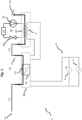
- Fig. 1 schematically shows an embodiment of a heat pump system 1 for heating water.
- the heat pump system 1 comprises a water flow system 10, having an inlet 11 to receive water to be heated and an outlet to discharge heated water 12.
- the heat pump comprises a compressor 21, a condenser 22, an expander 23 and an evaporator 24 forming a cycle through which a heat transfer fluid can be cycled.
- the heat transfer fluid transfers heat to the water to be heated by means of the condenser 22.
- the condenser 22 is thus in thermal contact with part of the water flow system 10.
- Fig. 1 further depicts an electronic control system 30.
- the electronic control system 30 may comprise a plurality of electronic circuits and elements. As an example a convertor 31 is shown.
- the heat pump system comprises a supplemental heating system 4 having one or more fixed resistive electronic elements (not shown) and one variable resistive electrical element 5.
- the electronic control system 30 is configured to distribute at least part of the supplemental power over the fixed resistive electrical elements and control the converter 31 to provide a modulated residual power to the variable resistive electrical element 5.
- part of the water flow system referred to as the cooling section 13 is in thermal contact with the electronic control system 30 and in particular with the convertor 31.
- the electronic control system 30 is depicted as a single unit but may in fact be formed by more than one different units and may be provided on a plurality of electronic boards or cards.
- the cooling section 13 is depicted schematically but may be formed by a plurality of cooling conduits passing the electronic control system.
- a renewable power source 3 e.g. solar panels
- the additional energy is used to heat the water by means of resistive electrical elements, including the variable resistive electrical element according to the embodiment shown in Fig. 1 .
- the electronic control system is implemented to optimize the use of the overproduction of electricity.
- the electronic control system 30 comprises elements that do not have a 100% efficiency, heat is generated. To re-use this waste heat, it is transmitted to the water in the cooling section 13.
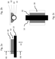
- thermal conducting elements 32 may be provided. This is shown in more detail in Fig.'s 2a-c.
- Fig. 2a shows a side view of part of an electronic control system 30, i.e. an electronic board or card and part of the cooling section 13 configured to transport water to be heated.
- Fig. 2b shows a cross sectional view of Fig. 2a , as indicated by the dashed line and references IIB in Fig. 2a.
- Fig. 2b also shows the water inside the cooling section 13.
- Fig. 2c shows a bottom view of Fig. 2a , as indicated by the arrow and reference IIC in Fig. 2a .
- a thermal conducting element 32 is provided connecting the electronic control system 30, i.e. the electronic board or card, to the cooling section 13.
- water to be heated by the heat pump system 1 circulates in a network of pipes, tanks and various heat exchangers.
- Heat exchange between the electronic control system 30 and the water to be heated is preferably achieved by thermal conductivity between the electronic control system 30 and at least one of the elements of the water flow system 10.
- Thermal conductive materials are therefore installed between the electronic control system 30 and the cooling section 13, with the objective of having a surface and an efficiency of exchange allowing to transmit thermal energy lost by the electronic control system 30 to the water.
- Different components such as a thermally conductive film, thermally conductive paste or thermally conductive materials (copper, aluminium etc...) can be used.
- the embodiment described make it possible to re-use the energy lost during the electronic regulation. This significantly improves the overall efficiency of the heating solution.
- the electronic control system is known and so is the power consumption and associated heat loss. This allows the heat pump system and the cooling part to be optimally dimensioned to exploit as much of the energy as possible in an efficient manner.
- the electronic control system does not produce significant heat, for instance when the supplemental heating system, comprising a plurality of resistive electronic elements, does not work, there is no loss to compensate and therefore no counter-performance.
- the system always works only in the desired direction.
Landscapes
- Engineering & Computer Science (AREA)
- Physics & Mathematics (AREA)
- Thermal Sciences (AREA)
- Mechanical Engineering (AREA)
- General Engineering & Computer Science (AREA)
- Chemical & Material Sciences (AREA)
- Combustion & Propulsion (AREA)
- Heat-Pump Type And Storage Water Heaters (AREA)
Priority Applications (2)
| Application Number | Priority Date | Filing Date | Title |
|---|---|---|---|
| EP22200956.5A EP4354026A1 (de) | 2022-10-11 | 2022-10-11 | Wärmepumpensystem und verfahren zum betrieb eines wärmepumpensystems |
| PCT/EP2023/077679 WO2024078980A1 (en) | 2022-10-11 | 2023-10-06 | Heat pump system and method of operating a heat pump system |
Applications Claiming Priority (1)
| Application Number | Priority Date | Filing Date | Title |
|---|---|---|---|
| EP22200956.5A EP4354026A1 (de) | 2022-10-11 | 2022-10-11 | Wärmepumpensystem und verfahren zum betrieb eines wärmepumpensystems |
Publications (1)
| Publication Number | Publication Date |
|---|---|
| EP4354026A1 true EP4354026A1 (de) | 2024-04-17 |
Family
ID=83690439
Family Applications (1)
| Application Number | Title | Priority Date | Filing Date |
|---|---|---|---|
| EP22200956.5A Pending EP4354026A1 (de) | 2022-10-11 | 2022-10-11 | Wärmepumpensystem und verfahren zum betrieb eines wärmepumpensystems |
Country Status (2)
| Country | Link |
|---|---|
| EP (1) | EP4354026A1 (de) |
| WO (1) | WO2024078980A1 (de) |
Citations (4)
| Publication number | Priority date | Publication date | Assignee | Title |
|---|---|---|---|---|
| EP2098802A2 (de) * | 2008-03-04 | 2009-09-09 | BSH Bosch und Siemens Hausgeräte GmbH | Warmwassergerät mit einem Elektronikkühlrohr |
| US20150354833A1 (en) * | 2012-04-09 | 2015-12-10 | David Kreutzman | Renewable energy hot water heater with heat pump |
| WO2019215240A1 (de) * | 2018-05-08 | 2019-11-14 | Stiebel Eltron Gmbh & Co.Kg | Heizungs- und/oder warmwasserbereitungssystem |
| EP3650769A1 (de) * | 2017-07-04 | 2020-05-13 | Mitsubishi Electric Corporation | Wärmeaustauscheinheit für klimaanlage |
-
2022
- 2022-10-11 EP EP22200956.5A patent/EP4354026A1/de active Pending
-
2023
- 2023-10-06 WO PCT/EP2023/077679 patent/WO2024078980A1/en unknown
Patent Citations (4)
| Publication number | Priority date | Publication date | Assignee | Title |
|---|---|---|---|---|
| EP2098802A2 (de) * | 2008-03-04 | 2009-09-09 | BSH Bosch und Siemens Hausgeräte GmbH | Warmwassergerät mit einem Elektronikkühlrohr |
| US20150354833A1 (en) * | 2012-04-09 | 2015-12-10 | David Kreutzman | Renewable energy hot water heater with heat pump |
| EP3650769A1 (de) * | 2017-07-04 | 2020-05-13 | Mitsubishi Electric Corporation | Wärmeaustauscheinheit für klimaanlage |
| WO2019215240A1 (de) * | 2018-05-08 | 2019-11-14 | Stiebel Eltron Gmbh & Co.Kg | Heizungs- und/oder warmwasserbereitungssystem |
Also Published As
| Publication number | Publication date |
|---|---|
| WO2024078980A1 (en) | 2024-04-18 |
Similar Documents
| Publication | Publication Date | Title |
|---|---|---|
| US10753236B2 (en) | Fuel vaporization using data center waste heat | |
| CN101815868A (zh) | 具有电子装置冷却系统的压缩机组件及方法 | |
| CN101849311A (zh) | 具有热回收的热泵 | |
| CN108601314A (zh) | 一种液冷系统及流量调节方法 | |
| US11098932B2 (en) | Method for air-conditioning of environments in the marine field | |
| US10631442B2 (en) | Cooling system, cooled computer system and computer facility | |
| JP2013160415A (ja) | 熱源システムおよび熱源システムの制御方法 | |
| CN206207598U (zh) | 空调器 | |
| JP2018168746A (ja) | 圧縮空気貯蔵発電装置 | |
| EP4354026A1 (de) | Wärmepumpensystem und verfahren zum betrieb eines wärmepumpensystems | |
| EP1883775B1 (de) | Heizsystem | |
| CN104626925A (zh) | 电动车热管理系统 | |
| EP3482136B1 (de) | Heizsystem | |
| US20220074604A1 (en) | Heating system | |
| CN111584898B (zh) | 燃料电池系统 | |
| CN115066583A (zh) | 热能组件 | |
| KR20150100827A (ko) | 파워 플랜트용 사전 가열 시스템 | |
| Thompson | Cool system, hot results | |
| US20230106883A1 (en) | Energy-efficient fluid distributor for server racks | |
| GB1596786A (en) | Energy storage devices | |
| WO2022115029A1 (en) | Domestic cold water heat exchanger arrangement | |
| CN112902441A (zh) | 一种暖风系统及方法 | |
| WO2022212000A1 (en) | Multi-stage thermal management system |
Legal Events
| Date | Code | Title | Description |
|---|---|---|---|
| PUAI | Public reference made under article 153(3) epc to a published international application that has entered the european phase |
Free format text: ORIGINAL CODE: 0009012 |
|
| STAA | Information on the status of an ep patent application or granted ep patent |
Free format text: STATUS: THE APPLICATION HAS BEEN PUBLISHED |
|
| AK | Designated contracting states |
Kind code of ref document: A1 Designated state(s): AL AT BE BG CH CY CZ DE DK EE ES FI FR GB GR HR HU IE IS IT LI LT LU LV MC ME MK MT NL NO PL PT RO RS SE SI SK SM TR |