EP4353973A1 - Compressor - Google Patents
Compressor Download PDFInfo
- Publication number
- EP4353973A1 EP4353973A1 EP22816233.5A EP22816233A EP4353973A1 EP 4353973 A1 EP4353973 A1 EP 4353973A1 EP 22816233 A EP22816233 A EP 22816233A EP 4353973 A1 EP4353973 A1 EP 4353973A1
- Authority
- EP
- European Patent Office
- Prior art keywords
- boss portion
- front head
- contact surface
- muffler
- compressor
- Prior art date
- Legal status (The legal status is an assumption and is not a legal conclusion. Google has not performed a legal analysis and makes no representation as to the accuracy of the status listed.)
- Granted
Links
Images



Classifications
-
- F—MECHANICAL ENGINEERING; LIGHTING; HEATING; WEAPONS; BLASTING
- F04—POSITIVE - DISPLACEMENT MACHINES FOR LIQUIDS; PUMPS FOR LIQUIDS OR ELASTIC FLUIDS
- F04B—POSITIVE-DISPLACEMENT MACHINES FOR LIQUIDS; PUMPS
- F04B39/00—Component parts, details, or accessories, of pumps or pumping systems specially adapted for elastic fluids, not otherwise provided for in, or of interest apart from, groups F04B25/00 - F04B37/00
- F04B39/0027—Pulsation and noise damping means
-
- F—MECHANICAL ENGINEERING; LIGHTING; HEATING; WEAPONS; BLASTING
- F04—POSITIVE - DISPLACEMENT MACHINES FOR LIQUIDS; PUMPS FOR LIQUIDS OR ELASTIC FLUIDS
- F04B—POSITIVE-DISPLACEMENT MACHINES FOR LIQUIDS; PUMPS
- F04B39/00—Component parts, details, or accessories, of pumps or pumping systems specially adapted for elastic fluids, not otherwise provided for in, or of interest apart from, groups F04B25/00 - F04B37/00
- F04B39/12—Casings; Cylinders; Cylinder heads; Fluid connections
- F04B39/125—Cylinder heads
-
- F—MECHANICAL ENGINEERING; LIGHTING; HEATING; WEAPONS; BLASTING
- F04—POSITIVE - DISPLACEMENT MACHINES FOR LIQUIDS; PUMPS FOR LIQUIDS OR ELASTIC FLUIDS
- F04C—ROTARY-PISTON, OR OSCILLATING-PISTON, POSITIVE-DISPLACEMENT MACHINES FOR LIQUIDS; ROTARY-PISTON, OR OSCILLATING-PISTON, POSITIVE-DISPLACEMENT PUMPS
- F04C18/00—Rotary-piston pumps specially adapted for elastic fluids
- F04C18/30—Rotary-piston pumps specially adapted for elastic fluids having the characteristics covered by two or more of groups F04C18/02, F04C18/08, F04C18/22, F04C18/24, F04C18/48, or having the characteristics covered by one of these groups together with some other type of movement between co-operating members
- F04C18/34—Rotary-piston pumps specially adapted for elastic fluids having the characteristics covered by two or more of groups F04C18/02, F04C18/08, F04C18/22, F04C18/24, F04C18/48, or having the characteristics covered by one of these groups together with some other type of movement between co-operating members having the movement defined in group F04C18/08 or F04C18/22 and relative reciprocation between the co-operating members
-
- F—MECHANICAL ENGINEERING; LIGHTING; HEATING; WEAPONS; BLASTING
- F04—POSITIVE - DISPLACEMENT MACHINES FOR LIQUIDS; PUMPS FOR LIQUIDS OR ELASTIC FLUIDS
- F04C—ROTARY-PISTON, OR OSCILLATING-PISTON, POSITIVE-DISPLACEMENT MACHINES FOR LIQUIDS; ROTARY-PISTON, OR OSCILLATING-PISTON, POSITIVE-DISPLACEMENT PUMPS
- F04C18/00—Rotary-piston pumps specially adapted for elastic fluids
- F04C18/30—Rotary-piston pumps specially adapted for elastic fluids having the characteristics covered by two or more of groups F04C18/02, F04C18/08, F04C18/22, F04C18/24, F04C18/48, or having the characteristics covered by one of these groups together with some other type of movement between co-operating members
- F04C18/34—Rotary-piston pumps specially adapted for elastic fluids having the characteristics covered by two or more of groups F04C18/02, F04C18/08, F04C18/22, F04C18/24, F04C18/48, or having the characteristics covered by one of these groups together with some other type of movement between co-operating members having the movement defined in group F04C18/08 or F04C18/22 and relative reciprocation between the co-operating members
- F04C18/356—Rotary-piston pumps specially adapted for elastic fluids having the characteristics covered by two or more of groups F04C18/02, F04C18/08, F04C18/22, F04C18/24, F04C18/48, or having the characteristics covered by one of these groups together with some other type of movement between co-operating members having the movement defined in group F04C18/08 or F04C18/22 and relative reciprocation between the co-operating members with vanes reciprocating with respect to the outer member
-
- F—MECHANICAL ENGINEERING; LIGHTING; HEATING; WEAPONS; BLASTING
- F04—POSITIVE - DISPLACEMENT MACHINES FOR LIQUIDS; PUMPS FOR LIQUIDS OR ELASTIC FLUIDS
- F04C—ROTARY-PISTON, OR OSCILLATING-PISTON, POSITIVE-DISPLACEMENT MACHINES FOR LIQUIDS; ROTARY-PISTON, OR OSCILLATING-PISTON, POSITIVE-DISPLACEMENT PUMPS
- F04C29/00—Component parts, details or accessories of pumps or pumping installations, not provided for in groups F04C18/00 - F04C28/00
- F04C29/06—Silencing
- F04C29/065—Noise dampening volumes, e.g. muffler chambers
-
- F—MECHANICAL ENGINEERING; LIGHTING; HEATING; WEAPONS; BLASTING
- F04—POSITIVE - DISPLACEMENT MACHINES FOR LIQUIDS; PUMPS FOR LIQUIDS OR ELASTIC FLUIDS
- F04C—ROTARY-PISTON, OR OSCILLATING-PISTON, POSITIVE-DISPLACEMENT MACHINES FOR LIQUIDS; ROTARY-PISTON, OR OSCILLATING-PISTON, POSITIVE-DISPLACEMENT PUMPS
- F04C29/00—Component parts, details or accessories of pumps or pumping installations, not provided for in groups F04C18/00 - F04C28/00
- F04C29/06—Silencing
- F04C29/068—Silencing the silencing means being arranged inside the pump housing
-
- F—MECHANICAL ENGINEERING; LIGHTING; HEATING; WEAPONS; BLASTING
- F04—POSITIVE - DISPLACEMENT MACHINES FOR LIQUIDS; PUMPS FOR LIQUIDS OR ELASTIC FLUIDS
- F04C—ROTARY-PISTON, OR OSCILLATING-PISTON, POSITIVE-DISPLACEMENT MACHINES FOR LIQUIDS; ROTARY-PISTON, OR OSCILLATING-PISTON, POSITIVE-DISPLACEMENT PUMPS
- F04C23/00—Combinations of two or more pumps, each being of rotary-piston or oscillating-piston type, specially adapted for elastic fluids; Pumping installations specially adapted for elastic fluids; Multi-stage pumps specially adapted for elastic fluids
- F04C23/008—Hermetic pumps
Definitions
- the present disclosure relates to a compressor.
- PTL 1 Japanese Unexamined Patent Publication No. 05-133377 discloses a compressor in which a space (shell space), into which a fluid compressed in a compression element is discharged, is formed by a front head (upper frame body) and a muffler cover (muffler).
- a space shell space
- muffler cover muffler
- the position of a fluid discharge port formed in the muffler cover is adjusted to cancel the pressure pulsation of the fluid discharged from the compression element so that the vibration and noise of the casing caused by the pressure pulsation are reduced.
- the muffler cover included in the compressor of PTL 1 is provided with an opening through which a boss portion of the front head is inserted. There is a slight clearance between the opening and the boss portion in a state where the muffler cover is attached to the front head, and therefore there is a problem in that it is difficult to sufficiently obtain a reduction effect of the vibration and noise due to the fluid compressed by the cylinder and flowing out through the clearance.
- the present disclosure proposes a compressor that suppresses the vibration and noise caused by pressure pulsation of a compressed refrigerant flowing out from a compression mechanism.
- a compressor includes a compression mechanism.
- the compression mechanism includes a front head including a boss portion and a muffler cover attached to the front head.
- the front head includes a first contact surface that is part of a conical side surface on an outer peripheral surface of the boss portion.
- the muffler cover includes a first surface having a circular first opening formed therein, into which the boss portion is inserted. A first end portion of the first surface forming the first opening is in contact with the first contact surface in a state where the muffler cover is attached to the front head.
- the gap between the boss portion and the first opening is sealed by the contact between the first contact surface and the first end portion of the first surface so that the refrigerant is prevented from flowing out through the gap between the boss portion and the first opening.
- the compressor suppresses the occurrence of vibration and noise caused by pressure pulsation of the compressed refrigerant flowing out from the compression mechanism.
- a compressor according to a second aspect is the compressor according to the first aspect, and the first surface includes a second contact surface that is part of a conical side surface formed around the first opening.
- the second contact surface is in contact with the first contact surface in a state where the muffler cover is attached to the front head.
- the gap between the boss portion and the first opening is sealed by the contact between the first contact surface and the second contact surface so that the refrigerant is prevented from flowing out through the gap between the boss portion and the first opening.
- the compressor suppresses the occurrence of vibration and noise caused by pressure pulsation of the compressed refrigerant flowing out from the compression mechanism.
- a compressor according to a third aspect is the compressor according to the first aspect or the second aspect, and the muffler cover has two second openings formed therein, through which a fluid compressed by the compression mechanism passes.
- the two second openings are formed on a circumference of a predetermined radius around an axial center of the boss portion in positions at intervals of 180° with the axial center as an axis.
- the refrigerant discharged from the second openings serves as a symmetric sound source, and the occurrence of vibration and noise caused by pressure pulsation of the compressed refrigerant is effectively suppressed.
- a compressor according to a fourth aspect is the compressor according to the second aspect or the third aspect and, on a plane including the axial center of the boss portion, an angle formed between the axial center of the boss portion and the first contact surface is smaller than an angle formed between the axial center of the boss portion and the second contact surface.
- the compressor when a downward load is applied to the muffler cover, the second contact surface is elastically deformed to come into surface contact with the first contact surface, and thus the occurrence of vibration and noise caused by pressure pulsation of the compressed refrigerant is effectively suppressed.
- a compressor according to a fifth aspect is the compressor according to any one of the second aspect to the fourth aspect, and a width of the second contact surface is larger than a plate thickness of the muffler cover.
- the elastic deformation of the second contact surface may ensure the sealing property, and the occurrence of vibration and noise caused by pressure pulsation of the compressed refrigerant is effectively suppressed.
- a compressor according to a sixth aspect is the compressor according to any one of the first aspect to the fifth aspect and, on a plane including the axial center of the boss portion, an angle formed between the axial center of the boss portion and the first contact surface is more than 0° and less than 45°.
- the compressor prevents a reduction in the volume of the space formed by the muffler cover and the front head due to an excessive increase in the outer peripheral diameter of the boss portion below the first contact surface, and therefore the occurrence of vibration and noise caused by pressure pulsation of the compressed refrigerant is effectively suppressed.
- Fig. 1 is a schematic longitudinal sectional view of a compressor 10 according to a first embodiment.
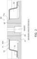
- Fig. 2 is an enlarged view of a portion A surrounded by a dotted line in Fig. 1 .
- the compressor 10 is a rotary compressor in which a piston is eccentrically rotated inside a cylinder to change the volume of a space inside the cylinder and thus compress a fluid into a predetermined pressure.
- the compressor 10 is used to compress a refrigerant in a refrigeration cycle device such as an air conditioner or a heat pump type water heater.
- the compressor 10 includes a substantially cylindrical casing 11 serving as a sealed container, a drive mechanism 20 accommodated in the casing 11, and a compression mechanism 30 serving as a compression element.
- the compressor 10 suctions the refrigerant from a suction pipe 96 and discharges the refrigerant, which is compressed to have a high temperature and a high pressure, from a discharge pipe 25 toward a heat exchanger of a refrigeration apparatus (not illustrated).
- the drive mechanism 20 drives the compression mechanism 30.
- the drive mechanism 20 is housed above the compression mechanism 30 inside the casing 11.
- the drive mechanism 20 includes a motor 21 as a drive source and a shaft 22 as a drive shaft attached to the motor 21.
- the motor 21 and the shaft 22 are provided such that their axial centers coincide with an axis O.
- the motor 21 primarily includes a rotor 23 and a stator 24.
- the rotor 23 has a columnar shape.
- the shaft 22 is fixed to the rotor 23 such that their axial centers coincide with each other.
- the rotor 23 includes laminated electromagnetic steel plates and a magnet embedded in a rotor body.
- the stator 24 has a cylindrical shape and is fixed to an inner peripheral surface of the casing 11.
- the rotor 23 is provided on a radially inner side of the stator 24 via a space (air gap) having a predetermined width.
- the stator 24 is formed by using laminated electromagnetic steel plates and a coil wound around a stator body.
- the rotor 23 rotates together with the shaft 22 by an electromagnetic force generated in the stator 24 when a current flows through the coil. (2-1-2) Shaft
- the shaft 22 transmits the rotation of the motor 21 to the compression mechanism 30.
- the shaft 22 includes a crankpin 22a that is provided below the rotor 23 and is eccentric from the axial center.
- the crankpin 22a is inserted into a piston 31, described below, of the compression mechanism 30 in a state where the rotational force from the rotor 23 is transmittable.
- the crankpin 22a eccentrically rotates around the axial center and causes the piston 31 of the compression mechanism 30 to revolve around the axial center.
- the driving force of the motor 21 is transmitted to the compression mechanism 30 via the shaft 22.
- the compression mechanism 30 suctions and compresses the refrigerant via the suction pipe 96.
- the compression mechanism 30 is housed below the drive mechanism 20 inside the casing 11.
- the compression mechanism 30 is a rotary compression mechanism and primarily includes a front head 40, a cylinder 50, the piston 31, a rear head 60, and a muffler cover 70.
- the refrigerant compressed by the compression mechanism 30 is discharged from a discharge hole (not illustrated) to a space between the motor 21 and the compression mechanism 30 through a muffler space S2 described below.
- the cylinder 50 forms a compression chamber S1, which compresses the refrigerant, together with the piston 31 housed inside.
- the cylinder 50 is a plate-shaped member that has a predetermined width and is provided to be perpendicular to the vertical direction.
- the cylinder 50 includes a suction passage 51 and a cylinder chamber 52.
- the cylinder chamber 52 is formed by closing a through-hole, which is formed in the vertical direction of the cylinder 50 and has a substantially circular shape in a plan view, with the rear head 60 from below and the front head 40 from above.
- the suction passage 51 is a refrigerant channel that communicates between the cylinder chamber 52 and the outside of the cylinder 50.
- One end of the suction passage 51 is opened to the cylinder chamber 52, and the other end of the suction passage 51 is opened to an outer surface of the cylinder chamber 52.
- a distal end portion of the suction pipe 96 is inserted into the other end of the suction passage 51.
- the cylinder chamber 52 accommodates the piston 31.
- the piston 31 is a plate member that is circular in a plan view and is accommodated in the cylinder chamber 52.
- the piston 31 is integrally mounted on the crankpin 22a of the shaft 22.
- the piston 31 revolves around the axis O with part of the outer peripheral surface in contact with the inner peripheral surface of the cylinder 50 forming the cylinder chamber 52 as viewed from above.
- the front head 40 includes a front head disk portion 41 that closes an upper surface of the cylinder 50 and a front head boss portion 42 that extends upward from a peripheral edge of an opening formed in the center of the front head disk portion 41.
- the front head 40 is fixed to the casing 11.
- the front head disk portion 41 is provided with a discharge hole (not illustrated).
- the refrigerant compressed in the compression chamber S1 whose volume changes in the cylinder chamber 52 of the cylinder 50 is discharged through the discharge hole.
- the front head disk portion 41 is provided with a discharge valve (not illustrated) that opens and closes an outlet of the discharge hole.
- the discharge valve opens to allow the refrigerant to be discharged into the muffler space S2 through the discharge hole.
- the front head boss portion 42 has a cylindrical shape.
- the front head boss portion 42 has the shaft 22 inserted into the inner periphery thereof and functions as a bearing of the shaft 22.
- the front head boss portion 42 is formed such that an axial center 42o coincides with the axis O.
- the front head 40 includes a first contact surface 42a that is part of a conical side surface on the outer peripheral surface of the front head boss portion 42.
- the first contact surface 42a forms a side surface of a truncated cone whose diameter increases from top to bottom.
- an angle a1 formed between the axial center 42o and the first contact surface 42a is preferably more than 0° and less than 45°.
- the rear head 60 includes a rear head disk portion 61 that closes a lower surface of the cylinder 50 and a rear head boss portion 62 that extends downward from a peripheral edge portion of an opening formed in the center of the rear head disk portion 61.
- the rear head boss portion 62 has a cylindrical shape.
- the rear head boss portion 62 has the shaft 22 inserted into the inner periphery thereof and functions as a bearing of the shaft 22.
- the muffler cover 70 is a member that forms the muffler space S2 to reduce vibration and noise caused by pressure pulsation of the refrigerant discharged from the compression mechanism 30.
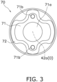
- Fig. 3 is a plan view of the muffler cover 70 as viewed from above.
- the muffler cover 70 primarily includes an upper surface 71, which is a surface perpendicular to the vertical direction, and a side surface 72 extending downward from an outer peripheral edge of the upper surface 71.
- the upper surface 71 is provided with a first muffler opening 71a and two second muffler openings 71b.
- the muffler cover 70 is formed of, but not limited thereto, a metal plate having a plate thickness t of approximately 1 mm.
- the upper surface 71 is an example of a first surface.
- the first muffler opening 71a is a circular opening formed to cause the front head boss portion 42 to penetrate therethrough.
- the first muffler opening 71a is formed such that a first end portion 71e of the upper surface 71 forming the first muffler opening 71a is in contact with the first contact surface 42a in a state where the muffler cover 70 is attached to the front head 40. According to the present embodiment, as illustrated in Fig.
- the first muffler opening 71a is formed such that the lower end of the first end portion 71e comes into contact (line contact) with the first contact surface 42a in a state where the front head boss portion 42 is inserted from under the first muffler opening 71a and the muffler cover 70 is attached to the upper surface of the front head 40.
- the first muffler opening 71a is an example of a first opening.
- the second muffler opening 71b is a circular opening formed to cause the refrigerant to flow from the muffler space S2 into the space between the motor 21 and the compression mechanism 30.
- the two muffler openings 70b are formed on the circumference of a predetermined radius around the axial center 42o of the front head boss portion 42 in positions at intervals of 180° with the axial center 42o as an axis (see Fig. 3 ).
- the two second muffler openings 71b when viewed in the extending direction of the front head boss portion 42, are formed in positions such that the centers thereof are located on the circumference of a predetermined radius around the axial center 42o of the front head boss portion 42 and the centers thereof have an interval of 180° with the axial center 42o as an axis.
- the second muffler opening 71b is an example of a second opening.
- the muffler cover 70 is attached to the front head disk portion 41 in a state where the front head boss portion 42 is inserted into the first muffler opening 71a.
- the muffler cover 70 forms the muffler space S2 together with the upper surface of the front head disk portion 41 and the outer peripheral surface of the front head boss portion 42.
- the first end portion 71e of the upper surface 71 is in contact with the first contact surface 42a.
- the eccentric rotation of the crankpin 22a causes the piston 31 of the compression mechanism 30 to revolve inside the cylinder chamber 52, which changes the volume of the compression chamber S1.
- the refrigerant is suctioned into the compression chamber S1 through the suction passage 51.
- the suctioned refrigerant is compressed by the piston 31 and flows out to the muffler space S2 through the discharge hole.
- the refrigerant having flowed out to the muffler space S2 is discharged into the space between the motor 21 and the compression mechanism 30 through the two second muffler openings 71b of the muffler cover 70.
- the refrigerant discharged to the outside of the muffler space S2 passes through the air gap between the rotor 23 and the stator 24 of the motor 21 and is discharged from the discharge pipe 25.
- the two second muffler openings 71b are formed on the circumference of a predetermined radius around the axial center 42o of the front head boss portion 42 in positions at intervals of 180° with the axial center 42o as an axis, and therefore the refrigerant discharged from the second muffler openings 71b serves as a symmetric sound source.
- the occurrence of standing waves caused by pressure pulsation of the refrigerant flowing out of the compression mechanism 30 is suppressed, and the occurrence of vibration and noise caused by the standing waves is suppressed.
- the compressor 10 includes the compression mechanism 30.
- the compression mechanism 30 includes the front head 40 including the front head boss portion 42 and the muffler cover 70 attached to the front head 40.
- the front head 40 includes the first contact surface 42a that is part of the conical side surface on the outer peripheral surface of the front head boss portion 42.
- the muffler cover 70 includes the upper surface 71 having the circular first muffler opening 71a formed therein, into which the front head boss portion 42 is inserted.
- the first end portion 71e of the first surface 71 forming the first muffler opening 71a is in contact with the first contact surface 42a in a state where the muffler cover 70 is attached to the front head 40.
- the front head boss portion 42 is inserted from under the first muffler opening 71a so that the first contact surface 42a and the first end portion 71e may be in line contact with each other. Accordingly, the gap between the front head boss portion 42 and the first muffler opening 71a is sealed by the first contact surface 42a and the lower end of the first end portion 71e so that the refrigerant is prevented from flowing out through the gap between the front head boss portion 42 and the first muffler opening 71a. As a result, the compressor 10 suppresses the occurrence of vibration and noise caused by pressure pulsation of the compressed refrigerant flowing out from the compression mechanism 30.
- the compressor according to the related art disclosed in PTL 1 is designed to reduce the gap (clearance) between the front head boss portion and the boss portion of the muffler cover with the intention of preventing the refrigerant from flowing out through the gap between both members.
- the reduced gap causes a problem of a reduction in assemblability.
- the compressor 10 as the first contact surface 42a, which is part of the conical side surface, and the first end portion 71e are in contact with each other, the sealing property may be ensured without designing the small clearance between the outer diameter of the front head boss portion 42 and the inner diameter of the first muffler opening 71a. Therefore, the compressor 10 suppresses the occurrence of vibration and noise caused by pressure pulsation of the compressed refrigerant without causing deterioration in assemblability.
- the compressor 10 suppresses the clearance formed between the first contact surface 42a of the front head boss portion 42 and the first muffler opening 71a, and thus the muffler cover 70 may be positioned in the horizontal direction more easily than in the related art.
- the muffler cover 70 is provided with the two second muffler openings 71b through which the refrigerant compressed by the compression mechanism 30 passes.
- the two second muffler openings 71b are formed on the circumference of a predetermined radius around the axial center 42o of the front head boss portion 42 in positions at intervals of 180° with the axial center 42o as an axis.
- the refrigerant discharged from the second muffler openings 71b serves as a symmetric sound source, and the occurrence of vibration and noise caused by pressure pulsation of the compressed refrigerant is effectively suppressed.
- Fig. 4 is a schematic longitudinal sectional view of the compressor 10 according to a second embodiment.
- Fig. 5 is an enlarged view of a portion B surrounded by a dotted line in Fig. 4 .
- Fig. 6 is a cross-sectional view of the muffler cover 70 included in the compressor 10 according to the second embodiment.
- the difference between the compressor 10 according to the first embodiment and the compressor 10 according to the second embodiment is the shape of the muffler cover 70.
- the difference between the first embodiment and the second embodiment will be mainly described below.
- the same or corresponding features between the first embodiment and the second embodiment are denoted by the same reference numerals, and the description thereof will be omitted as appropriate.
- the upper surface 71 of the muffler cover 70 includes a second contact surface 71c that is part of the conical side surface formed around the first muffler opening 71a.
- the second contact surface 71c forms the side surface of the truncated cone whose diameter increases from top to bottom.
- the second contact surface 71c is formed to be in contact (surface contact) with the first contact surface 42a of the front head 40 in a state where the front head boss portion 42 is inserted from under the first muffler opening 71a and the muffler cover 70 is attached to the upper surface of the front head 40.
- the first end portion 71e is also in contact with the first contact surface 42a in a state where the muffler cover 70 is attached to the upper surface of the front head 40.
- the second contact surface 71c is preferably formed such that an angle a2 formed with the axial center 42o is larger than the angle a1 in the plane including the axial center 42o of the front head boss portion 42.
- the angle a1 is preferably smaller than the angle a2.
- a width W of the second contact surface 71c is preferably larger than the plate thickness t of the muffler cover 70.
- the upper surface 71 includes the second contact surface 71c that is part of the conical side surface formed around the first muffler opening 71a.
- the second contact surface 71c is in contact with the first contact surface 42a in a state where the muffler cover 70 is attached to the front head 40.
- the first contact surface 42a and the second contact surface 71c may be in surface contact with each other in addition to the first end portion 71e when the front head boss portion 42 is inserted from under the first muffler opening 71a.
- the gap between the front head boss portion 42 and the first muffler opening 71a is sealed by the first contact surface 42a and the second contact surface 71c so that the refrigerant is prevented from flowing out through the gap between the front head boss portion 42 and the first muffler opening 71a.
- the compressor 10 according to the second embodiment effectively suppresses the occurrence of vibration and noise caused by pressure pulsation of the compressed refrigerant flowing out from the compression mechanism 30.
- the elastic deformation of the second contact surface 71c may ensure the sealing property even when there is some variation in the dimension of the first contact surface 42a or the second contact surface 71c.
- the angle a1 formed between the axial center 42o of the front head boss portion 42 and the first contact surface 42a is smaller than the angle a2 formed between the axial center 42o of the front head boss portion 42 and the second contact surface 71c.
- the vicinity of the first end portion 71e of the second contact surface 71c comes into contact with the first contact surface 42a earlier than the other portions. Therefore, when a downward load is applied to the muffler cover 70, the second contact surface 71c is elastically deformed so that the area below the vicinity of the first end portion 71e may be further brought into surface contact. As a result, the occurrence of vibration and noise caused by pressure pulsation of the compressed refrigerant is effectively suppressed.
- the width w of the second contact surface 71c is larger than the plate thickness t of the muffler cover 70.
- the elastic deformation of the second contact surface 71c may ensure the sealing property, and the occurrence of vibration and noise caused by pressure pulsation of the compressed refrigerant is effectively suppressed.
- the angle a1 formed between the axial center 42o of the front head boss portion 42 and the first contact surface 42a is more than 0° and less than 45°.
- a model of a compressor according to an example and a model of a compressor according to a comparative example were created to analyze the radiated sound.
- a model of the compressor 10 according to the second embodiment illustrated in Fig. 4 was used as the example.
- the model of the compressor used as the comparative example is different from the compressor 10 only in that the first contact surface 42a and the second contact surface 71c are not provided.
- the muffler cover was arranged to be biased with respect to the front head boss portion.
- the clearance between the front head boss portion and the muffler cover was set to 0. 6 mm.
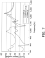
- Fig. 7 is a graph illustrating analysis results using the models according to the example and the comparative example.
Landscapes
- Engineering & Computer Science (AREA)
- Mechanical Engineering (AREA)
- General Engineering & Computer Science (AREA)
- Applications Or Details Of Rotary Compressors (AREA)
Abstract
Description
- The present disclosure relates to a compressor.
- PTL 1 (
Japanese Unexamined Patent Publication No. 05-133377 - The muffler cover included in the compressor of PTL 1 is provided with an opening through which a boss portion of the front head is inserted. There is a slight clearance between the opening and the boss portion in a state where the muffler cover is attached to the front head, and therefore there is a problem in that it is difficult to sufficiently obtain a reduction effect of the vibration and noise due to the fluid compressed by the cylinder and flowing out through the clearance.
- The present disclosure proposes a compressor that suppresses the vibration and noise caused by pressure pulsation of a compressed refrigerant flowing out from a compression mechanism.
- A compressor according to a first aspect includes a compression mechanism. The compression mechanism includes a front head including a boss portion and a muffler cover attached to the front head. The front head includes a first contact surface that is part of a conical side surface on an outer peripheral surface of the boss portion. The muffler cover includes a first surface having a circular first opening formed therein, into which the boss portion is inserted. A first end portion of the first surface forming the first opening is in contact with the first contact surface in a state where the muffler cover is attached to the front head.
- With the compressor, the gap between the boss portion and the first opening is sealed by the contact between the first contact surface and the first end portion of the first surface so that the refrigerant is prevented from flowing out through the gap between the boss portion and the first opening. As a result, the compressor suppresses the occurrence of vibration and noise caused by pressure pulsation of the compressed refrigerant flowing out from the compression mechanism.
- A compressor according to a second aspect is the compressor according to the first aspect, and the first surface includes a second contact surface that is part of a conical side surface formed around the first opening. The second contact surface is in contact with the first contact surface in a state where the muffler cover is attached to the front head.
- With the compressor, the gap between the boss portion and the first opening is sealed by the contact between the first contact surface and the second contact surface so that the refrigerant is prevented from flowing out through the gap between the boss portion and the first opening. As a result, the compressor suppresses the occurrence of vibration and noise caused by pressure pulsation of the compressed refrigerant flowing out from the compression mechanism.
- A compressor according to a third aspect is the compressor according to the first aspect or the second aspect, and the muffler cover has two second openings formed therein, through which a fluid compressed by the compression mechanism passes. When viewed in an extending direction of the boss portion, the two second openings are formed on a circumference of a predetermined radius around an axial center of the boss portion in positions at intervals of 180° with the axial center as an axis.
- With the compressor, the refrigerant discharged from the second openings serves as a symmetric sound source, and the occurrence of vibration and noise caused by pressure pulsation of the compressed refrigerant is effectively suppressed.
- A compressor according to a fourth aspect is the compressor according to the second aspect or the third aspect and, on a plane including the axial center of the boss portion, an angle formed between the axial center of the boss portion and the first contact surface is smaller than an angle formed between the axial center of the boss portion and the second contact surface.
- With the compressor, when a downward load is applied to the muffler cover, the second contact surface is elastically deformed to come into surface contact with the first contact surface, and thus the occurrence of vibration and noise caused by pressure pulsation of the compressed refrigerant is effectively suppressed.
- A compressor according to a fifth aspect is the compressor according to any one of the second aspect to the fourth aspect, and a width of the second contact surface is larger than a plate thickness of the muffler cover.
- With the compressor, even when there is some variation in the dimension of the first contact surface or the second contact surface, the elastic deformation of the second contact surface may ensure the sealing property, and the occurrence of vibration and noise caused by pressure pulsation of the compressed refrigerant is effectively suppressed.
- A compressor according to a sixth aspect is the compressor according to any one of the first aspect to the fifth aspect and, on a plane including the axial center of the boss portion, an angle formed between the axial center of the boss portion and the first contact surface is more than 0° and less than 45°.
- The compressor prevents a reduction in the volume of the space formed by the muffler cover and the front head due to an excessive increase in the outer peripheral diameter of the boss portion below the first contact surface, and therefore the occurrence of vibration and noise caused by pressure pulsation of the compressed refrigerant is effectively suppressed.
-
-
Fig. 1 is a schematic longitudinal sectional view of acompressor 10 according to a first embodiment. -
Fig. 2 is an enlarged view of a portion A surrounded by a dotted line inFig. 1 . -
Fig. 3 is a plan view of amuffler cover 70 as viewed from above. -
Fig. 4 is a schematic longitudinal sectional view of thecompressor 10 according to a second embodiment. -
Fig. 5 is an enlarged view of a portion B surrounded by a dotted line inFig. 4 . -
Fig. 6 is a cross-sectional view of themuffler cover 70 included in thecompressor 10 according to the second embodiment. -
Fig. 7 is a graph illustrating analysis results using models according to an example and a comparative example. -
Fig. 1 is a schematic longitudinal sectional view of acompressor 10 according to a first embodiment.Fig. 2 is an enlarged view of a portion A surrounded by a dotted line inFig. 1 . Thecompressor 10 is a rotary compressor in which a piston is eccentrically rotated inside a cylinder to change the volume of a space inside the cylinder and thus compress a fluid into a predetermined pressure. Although not limited, thecompressor 10 is used to compress a refrigerant in a refrigeration cycle device such as an air conditioner or a heat pump type water heater. Thecompressor 10 includes a substantially cylindrical casing 11 serving as a sealed container, adrive mechanism 20 accommodated in the casing 11, and acompression mechanism 30 serving as a compression element. Thecompressor 10 suctions the refrigerant from asuction pipe 96 and discharges the refrigerant, which is compressed to have a high temperature and a high pressure, from adischarge pipe 25 toward a heat exchanger of a refrigeration apparatus (not illustrated). - The up and down directions used in the description below are the directions indicated by arrows in
Fig. 1 . - The
drive mechanism 20 drives thecompression mechanism 30. Thedrive mechanism 20 is housed above thecompression mechanism 30 inside the casing 11. Thedrive mechanism 20 includes amotor 21 as a drive source and ashaft 22 as a drive shaft attached to themotor 21. Themotor 21 and theshaft 22 are provided such that their axial centers coincide with an axis O. - The
motor 21 primarily includes arotor 23 and astator 24. Therotor 23 has a columnar shape. Theshaft 22 is fixed to therotor 23 such that their axial centers coincide with each other. Therotor 23 includes laminated electromagnetic steel plates and a magnet embedded in a rotor body. Thestator 24 has a cylindrical shape and is fixed to an inner peripheral surface of the casing 11. Therotor 23 is provided on a radially inner side of thestator 24 via a space (air gap) having a predetermined width. Thestator 24 is formed by using laminated electromagnetic steel plates and a coil wound around a stator body. Therotor 23 rotates together with theshaft 22 by an electromagnetic force generated in thestator 24 when a current flows through the coil. (2-1-2) Shaft - The
shaft 22 transmits the rotation of themotor 21 to thecompression mechanism 30. Theshaft 22 includes acrankpin 22a that is provided below therotor 23 and is eccentric from the axial center. Thecrankpin 22a is inserted into apiston 31, described below, of thecompression mechanism 30 in a state where the rotational force from therotor 23 is transmittable. When theshaft 22 rotates, thecrankpin 22a eccentrically rotates around the axial center and causes thepiston 31 of thecompression mechanism 30 to revolve around the axial center. As a result, the driving force of themotor 21 is transmitted to thecompression mechanism 30 via theshaft 22. - The
compression mechanism 30 suctions and compresses the refrigerant via thesuction pipe 96. Thecompression mechanism 30 is housed below thedrive mechanism 20 inside the casing 11. Thecompression mechanism 30 is a rotary compression mechanism and primarily includes afront head 40, acylinder 50, thepiston 31, arear head 60, and amuffler cover 70. The refrigerant compressed by thecompression mechanism 30 is discharged from a discharge hole (not illustrated) to a space between themotor 21 and thecompression mechanism 30 through a muffler space S2 described below. - The
cylinder 50 forms a compression chamber S1, which compresses the refrigerant, together with thepiston 31 housed inside. Thecylinder 50 is a plate-shaped member that has a predetermined width and is provided to be perpendicular to the vertical direction. Thecylinder 50 includes asuction passage 51 and acylinder chamber 52. - The
cylinder chamber 52 is formed by closing a through-hole, which is formed in the vertical direction of thecylinder 50 and has a substantially circular shape in a plan view, with therear head 60 from below and thefront head 40 from above. - The
suction passage 51 is a refrigerant channel that communicates between thecylinder chamber 52 and the outside of thecylinder 50. One end of thesuction passage 51 is opened to thecylinder chamber 52, and the other end of thesuction passage 51 is opened to an outer surface of thecylinder chamber 52. A distal end portion of thesuction pipe 96 is inserted into the other end of thesuction passage 51. Thecylinder chamber 52 accommodates thepiston 31. - The
piston 31 is a plate member that is circular in a plan view and is accommodated in thecylinder chamber 52. Thepiston 31 is integrally mounted on thecrankpin 22a of theshaft 22. When theshaft 22 rotates, thepiston 31 revolves around the axis O with part of the outer peripheral surface in contact with the inner peripheral surface of thecylinder 50 forming thecylinder chamber 52 as viewed from above. - The
front head 40 includes a fronthead disk portion 41 that closes an upper surface of thecylinder 50 and a fronthead boss portion 42 that extends upward from a peripheral edge of an opening formed in the center of the fronthead disk portion 41. Thefront head 40 is fixed to the casing 11. - The front
head disk portion 41 is provided with a discharge hole (not illustrated). The refrigerant compressed in the compression chamber S1 whose volume changes in thecylinder chamber 52 of thecylinder 50 is discharged through the discharge hole. The fronthead disk portion 41 is provided with a discharge valve (not illustrated) that opens and closes an outlet of the discharge hole. When the pressure in the compression chamber S1 become higher than the pressure in the muffler space S2, because of the pressure gap, the discharge valve opens to allow the refrigerant to be discharged into the muffler space S2 through the discharge hole. - The front
head boss portion 42 has a cylindrical shape. The fronthead boss portion 42 has theshaft 22 inserted into the inner periphery thereof and functions as a bearing of theshaft 22. The fronthead boss portion 42 is formed such that an axial center 42o coincides with the axis O. - The
front head 40 includes afirst contact surface 42a that is part of a conical side surface on the outer peripheral surface of the fronthead boss portion 42. According to the present embodiment, thefirst contact surface 42a forms a side surface of a truncated cone whose diameter increases from top to bottom. In the plane including the axial center 42o of the fronthead boss portion 42, an angle a1 formed between the axial center 42o and thefirst contact surface 42a is preferably more than 0° and less than 45°. - The
rear head 60 includes a rearhead disk portion 61 that closes a lower surface of thecylinder 50 and a rearhead boss portion 62 that extends downward from a peripheral edge portion of an opening formed in the center of the rearhead disk portion 61. - The rear
head boss portion 62 has a cylindrical shape. The rearhead boss portion 62 has theshaft 22 inserted into the inner periphery thereof and functions as a bearing of theshaft 22. - The
muffler cover 70 is a member that forms the muffler space S2 to reduce vibration and noise caused by pressure pulsation of the refrigerant discharged from thecompression mechanism 30.Fig. 3 is a plan view of themuffler cover 70 as viewed from above. Themuffler cover 70 primarily includes anupper surface 71, which is a surface perpendicular to the vertical direction, and aside surface 72 extending downward from an outer peripheral edge of theupper surface 71. - The
upper surface 71 is provided with afirst muffler opening 71a and twosecond muffler openings 71b. Themuffler cover 70 is formed of, but not limited thereto, a metal plate having a plate thickness t of approximately 1 mm. Theupper surface 71 is an example of a first surface. - The
first muffler opening 71a is a circular opening formed to cause the fronthead boss portion 42 to penetrate therethrough. Thefirst muffler opening 71a is formed such that afirst end portion 71e of theupper surface 71 forming thefirst muffler opening 71a is in contact with thefirst contact surface 42a in a state where themuffler cover 70 is attached to thefront head 40. According to the present embodiment, as illustrated inFig. 2 , thefirst muffler opening 71a is formed such that the lower end of thefirst end portion 71e comes into contact (line contact) with thefirst contact surface 42a in a state where the fronthead boss portion 42 is inserted from under thefirst muffler opening 71a and themuffler cover 70 is attached to the upper surface of thefront head 40. Thefirst muffler opening 71a is an example of a first opening. - The
second muffler opening 71b is a circular opening formed to cause the refrigerant to flow from the muffler space S2 into the space between themotor 21 and thecompression mechanism 30. When viewed in the extending direction of the fronthead boss portion 42, the two muffler openings 70b are formed on the circumference of a predetermined radius around the axial center 42o of the fronthead boss portion 42 in positions at intervals of 180° with the axial center 42o as an axis (seeFig. 3 ). According to the present embodiment, when viewed in the extending direction of the fronthead boss portion 42, the twosecond muffler openings 71b are formed in positions such that the centers thereof are located on the circumference of a predetermined radius around the axial center 42o of the fronthead boss portion 42 and the centers thereof have an interval of 180° with the axial center 42o as an axis. Thesecond muffler opening 71b is an example of a second opening. - The
muffler cover 70 is attached to the fronthead disk portion 41 in a state where the fronthead boss portion 42 is inserted into thefirst muffler opening 71a. The muffler cover 70 forms the muffler space S2 together with the upper surface of the fronthead disk portion 41 and the outer peripheral surface of the fronthead boss portion 42. As described above, when themuffler cover 70 is attached to the upper surface of the fronthead disk portion 41, thefirst end portion 71e of theupper surface 71 is in contact with thefirst contact surface 42a. - When the
rotor 23 rotates, the eccentric rotation of thecrankpin 22a causes thepiston 31 of thecompression mechanism 30 to revolve inside thecylinder chamber 52, which changes the volume of the compression chamber S1. As a result, the refrigerant is suctioned into the compression chamber S1 through thesuction passage 51. The suctioned refrigerant is compressed by thepiston 31 and flows out to the muffler space S2 through the discharge hole. The refrigerant having flowed out to the muffler space S2 is discharged into the space between themotor 21 and thecompression mechanism 30 through the twosecond muffler openings 71b of themuffler cover 70. The refrigerant discharged to the outside of the muffler space S2 passes through the air gap between therotor 23 and thestator 24 of themotor 21 and is discharged from thedischarge pipe 25. - Furthermore, in the
compressor 10, when viewed in the extending direction of the fronthead boss portion 42, the twosecond muffler openings 71b are formed on the circumference of a predetermined radius around the axial center 42o of the fronthead boss portion 42 in positions at intervals of 180° with the axial center 42o as an axis, and therefore the refrigerant discharged from thesecond muffler openings 71b serves as a symmetric sound source. As a result, the occurrence of standing waves caused by pressure pulsation of the refrigerant flowing out of thecompression mechanism 30 is suppressed, and the occurrence of vibration and noise caused by the standing waves is suppressed. - The
compressor 10 includes thecompression mechanism 30. Thecompression mechanism 30 includes thefront head 40 including the fronthead boss portion 42 and themuffler cover 70 attached to thefront head 40. Thefront head 40 includes thefirst contact surface 42a that is part of the conical side surface on the outer peripheral surface of the fronthead boss portion 42. Themuffler cover 70 includes theupper surface 71 having the circularfirst muffler opening 71a formed therein, into which the fronthead boss portion 42 is inserted. Thefirst end portion 71e of thefirst surface 71 forming thefirst muffler opening 71a is in contact with thefirst contact surface 42a in a state where themuffler cover 70 is attached to thefront head 40. - In the
compressor 10, the fronthead boss portion 42 is inserted from under thefirst muffler opening 71a so that thefirst contact surface 42a and thefirst end portion 71e may be in line contact with each other. Accordingly, the gap between the fronthead boss portion 42 and thefirst muffler opening 71a is sealed by thefirst contact surface 42a and the lower end of thefirst end portion 71e so that the refrigerant is prevented from flowing out through the gap between the fronthead boss portion 42 and thefirst muffler opening 71a. As a result, thecompressor 10 suppresses the occurrence of vibration and noise caused by pressure pulsation of the compressed refrigerant flowing out from thecompression mechanism 30. - The compressor according to the related art disclosed in PTL 1 is designed to reduce the gap (clearance) between the front head boss portion and the boss portion of the muffler cover with the intention of preventing the refrigerant from flowing out through the gap between both members. However, the reduced gap causes a problem of a reduction in assemblability. On the other hand, in the
compressor 10, as thefirst contact surface 42a, which is part of the conical side surface, and thefirst end portion 71e are in contact with each other, the sealing property may be ensured without designing the small clearance between the outer diameter of the fronthead boss portion 42 and the inner diameter of thefirst muffler opening 71a. Therefore, thecompressor 10 suppresses the occurrence of vibration and noise caused by pressure pulsation of the compressed refrigerant without causing deterioration in assemblability. - In addition, the
compressor 10 suppresses the clearance formed between thefirst contact surface 42a of the fronthead boss portion 42 and thefirst muffler opening 71a, and thus themuffler cover 70 may be positioned in the horizontal direction more easily than in the related art. - The
muffler cover 70 is provided with the twosecond muffler openings 71b through which the refrigerant compressed by thecompression mechanism 30 passes. When viewed in the extending direction of the fronthead boss portion 42, the twosecond muffler openings 71b are formed on the circumference of a predetermined radius around the axial center 42o of the fronthead boss portion 42 in positions at intervals of 180° with the axial center 42o as an axis. - Thus, the refrigerant discharged from the
second muffler openings 71b serves as a symmetric sound source, and the occurrence of vibration and noise caused by pressure pulsation of the compressed refrigerant is effectively suppressed. -
Fig. 4 is a schematic longitudinal sectional view of thecompressor 10 according to a second embodiment.Fig. 5 is an enlarged view of a portion B surrounded by a dotted line inFig. 4 .Fig. 6 is a cross-sectional view of themuffler cover 70 included in thecompressor 10 according to the second embodiment. The difference between thecompressor 10 according to the first embodiment and thecompressor 10 according to the second embodiment is the shape of themuffler cover 70. The difference between the first embodiment and the second embodiment will be mainly described below. The same or corresponding features between the first embodiment and the second embodiment are denoted by the same reference numerals, and the description thereof will be omitted as appropriate. - In the
compressor 10 according to the second embodiment, theupper surface 71 of themuffler cover 70 includes asecond contact surface 71c that is part of the conical side surface formed around thefirst muffler opening 71a. - According to the present embodiment, the
second contact surface 71c forms the side surface of the truncated cone whose diameter increases from top to bottom. Thesecond contact surface 71c is formed to be in contact (surface contact) with thefirst contact surface 42a of thefront head 40 in a state where the fronthead boss portion 42 is inserted from under thefirst muffler opening 71a and themuffler cover 70 is attached to the upper surface of thefront head 40. In the same manner as the first embodiment, thefirst end portion 71e is also in contact with thefirst contact surface 42a in a state where themuffler cover 70 is attached to the upper surface of thefront head 40. - The
second contact surface 71c is preferably formed such that an angle a2 formed with the axial center 42o is larger than the angle a1 in the plane including the axial center 42o of the fronthead boss portion 42. In other words, the angle a1 is preferably smaller than the angle a2. Further, a width W of thesecond contact surface 71c is preferably larger than the plate thickness t of themuffler cover 70. - In the
compressor 10 according to the second embodiment, theupper surface 71 includes thesecond contact surface 71c that is part of the conical side surface formed around thefirst muffler opening 71a. Thesecond contact surface 71c is in contact with thefirst contact surface 42a in a state where themuffler cover 70 is attached to thefront head 40. - In the
compressor 10 according to the second embodiment, as both thefirst contact surface 42a and thesecond contact surface 71c are parts of the conical side surface, thefirst contact surface 42a and thesecond contact surface 71c may be in surface contact with each other in addition to thefirst end portion 71e when the fronthead boss portion 42 is inserted from under thefirst muffler opening 71a. Thus, the gap between the fronthead boss portion 42 and thefirst muffler opening 71a is sealed by thefirst contact surface 42a and thesecond contact surface 71c so that the refrigerant is prevented from flowing out through the gap between the fronthead boss portion 42 and thefirst muffler opening 71a. As a result, thecompressor 10 according to the second embodiment effectively suppresses the occurrence of vibration and noise caused by pressure pulsation of the compressed refrigerant flowing out from thecompression mechanism 30. - Furthermore, as the
first contact surface 42a and thesecond contact surface 71c are in surface contact with each other, the elastic deformation of thesecond contact surface 71c may ensure the sealing property even when there is some variation in the dimension of thefirst contact surface 42a or thesecond contact surface 71c. - In the plane including the axial center 42o of the front
head boss portion 42, the angle a1 formed between the axial center 42o of the fronthead boss portion 42 and thefirst contact surface 42a is smaller than the angle a2 formed between the axial center 42o of the fronthead boss portion 42 and thesecond contact surface 71c. - Thus, when the front
head boss portion 42 is inserted from under thefirst muffler opening 71a, the vicinity of thefirst end portion 71e of thesecond contact surface 71c comes into contact with thefirst contact surface 42a earlier than the other portions. Therefore, when a downward load is applied to themuffler cover 70, thesecond contact surface 71c is elastically deformed so that the area below the vicinity of thefirst end portion 71e may be further brought into surface contact. As a result, the occurrence of vibration and noise caused by pressure pulsation of the compressed refrigerant is effectively suppressed. - The width w of the
second contact surface 71c is larger than the plate thickness t of themuffler cover 70. - Thus, it is possible to elastically deform the
second contact surface 71c as appropriate while ensuring the area where thefirst contact surface 42a and thesecond contact surface 71c may be in surface contact with each other. Therefore, even when there is some variation in the dimension of thefirst contact surface 42a or thesecond contact surface 71c, the elastic deformation of thesecond contact surface 71c may ensure the sealing property, and the occurrence of vibration and noise caused by pressure pulsation of the compressed refrigerant is effectively suppressed. - In the plane including the axial center 42o of the front
head boss portion 42, the angle a1 formed between the axial center 42o of the fronthead boss portion 42 and thefirst contact surface 42a is more than 0° and less than 45°. - This prevents a reduction in the volume of the muffler space S2 due to an excessive increase in the outer peripheral diameter of the front
head boss portion 42 below thefirst contact surface 42a, and therefore the occurrence of vibration and noise caused by pressure pulsation of the compressed refrigerant is effectively suppressed. - A model of a compressor according to an example and a model of a compressor according to a comparative example were created to analyze the radiated sound.
- A model of the
compressor 10 according to the second embodiment illustrated inFig. 4 was used as the example. The model of the compressor used as the comparative example is different from thecompressor 10 only in that thefirst contact surface 42a and thesecond contact surface 71c are not provided. In the model of the compressor according to the comparative example, the muffler cover was arranged to be biased with respect to the front head boss portion. The clearance between the front head boss portion and the muffler cover was set to 0. 6 mm. - The above-described model was used to analyze the radiated sound (Sound Pressure Level [dB]) at a predetermined distance from the surface of the casing 11 when the fluid (refrigerant) was suctioned and discharged at a predetermined speed.
Fig. 7 is a graph illustrating analysis results using the models according to the example and the comparative example. - As illustrated in
Fig. 7 , with the use of thecompressor 10 to seal the gap between the fronthead boss portion 42 and thefirst muffler opening 71a, a reduction in the noise level was confirmed in a wide range of frequencies. - Although the embodiment of the present disclosure has been described above, it is understood that various modifications may be made to forms and details without departing from the spirit and scope of the present disclosure described in the scope of claims.
-
- 10
- Compressor
- 11
- Casing
- 20
- Drive mechanism
- 30
- Compression mechanism
- 40
- Front head
- 42
- Front head boss portion (boss portion)
- 42a
- First contact surface
- 42o
- Axial center
- 70
- Muffler cover
- 71
- Upper surface (first surface)
- 71a
- First muffler opening (first opening)
- 71b
- Second muffler opening (second opening)
- 71c
- Second contact surface
- a1
- Angle formed between axial center of front head boss portion and first contact surface
- a2
- Angle formed between axial center of front head boss portion and second contact surface
- w
- Width of second contact surface
- t
- Plate thickness of muffler cover
- PTL 1:
Japanese Unexamined Patent Publication No. 05-133377
Claims (6)
- A compressor (10) comprising a compression mechanism (30), whereinthe compression mechanism includes:a front head (40) including a boss portion (42); anda muffler cover (70) attached to the front head,the front head includes a first contact surface (42a) that is part of a conical side surface on an outer peripheral surface of the boss portion,the muffler cover includes a first surface (71) having a circular first opening (71a) formed therein, into which the boss portion is inserted, anda first end portion of the first surface forming the first opening is in contact with the first contact surface in a state where the muffler cover is attached to the front head.
- The compressor according to claim 1, whereinthe first surface includes a second contact surface (71c) that is part of a conical side surface formed around the first opening, andthe second contact surface is in contact with the first contact surface in a state where the muffler cover is attached to the front head.
- The compressor according to claim 1 or 2, whereinthe muffler cover has two second openings (71b) formed therein, through which a fluid compressed by the compression mechanism passes, andwhen viewed in an extending direction of the boss portion, the two second openings are formed on a circumference of a predetermined radius around an axial center (42o) of the boss portion in positions at intervals of 180° with the axial center as an axis.
- The compressor according to claim 2 or 3, wherein, on a plane including the axial center of the boss portion, an angle (a1) formed between the axial center of the boss portion and the first contact surface is smaller than an angle (a2) formed between the axial center of the boss portion and the second contact surface.
- The compressor according to any one of claims 2 to 4, wherein a width (w) of the second contact surface is larger than a plate thickness (t) of the muffler cover.
- The compressor according to any one of claims 1 to 5, wherein, on a plane including the axial center of the boss portion, an angle formed between the axial center of the boss portion and the first contact surface is more than 0° and less than 45°.
Applications Claiming Priority (2)
| Application Number | Priority Date | Filing Date | Title |
|---|---|---|---|
| JP2021093685 | 2021-06-03 | ||
| PCT/JP2022/022656 WO2022255488A1 (en) | 2021-06-03 | 2022-06-03 | Compressor |
Publications (3)
| Publication Number | Publication Date |
|---|---|
| EP4353973A1 true EP4353973A1 (en) | 2024-04-17 |
| EP4353973A4 EP4353973A4 (en) | 2024-10-23 |
| EP4353973B1 EP4353973B1 (en) | 2026-02-04 |
Family
ID=84322727
Family Applications (1)
| Application Number | Title | Priority Date | Filing Date |
|---|---|---|---|
| EP22816233.5A Active EP4353973B1 (en) | 2021-06-03 | 2022-06-03 | Compressor |
Country Status (5)
| Country | Link |
|---|---|
| US (1) | US12607189B2 (en) |
| EP (1) | EP4353973B1 (en) |
| JP (1) | JP7339572B2 (en) |
| CN (1) | CN117396676A (en) |
| WO (1) | WO2022255488A1 (en) |
Families Citing this family (1)
| Publication number | Priority date | Publication date | Assignee | Title |
|---|---|---|---|---|
| CN120537728B (en) * | 2025-04-27 | 2026-06-30 | 上海海立电器有限公司 | Sealing cover and refrigerant pump |
Family Cites Families (20)
| Publication number | Priority date | Publication date | Assignee | Title |
|---|---|---|---|---|
| JPS60180792U (en) * | 1984-05-11 | 1985-11-30 | 三洋電機株式会社 | rotary compressor |
| JPS63115590U (en) * | 1987-01-20 | 1988-07-26 | ||
| JPH078864Y2 (en) * | 1988-10-31 | 1995-03-06 | 株式会社東芝 | Compressor |
| JPH05133377A (en) | 1991-11-12 | 1993-05-28 | Sanyo Electric Co Ltd | Hermetic compressor |
| KR100324771B1 (en) * | 2000-04-25 | 2002-02-20 | 구자홍 | Double-stage enclosed compressor |
| KR100504913B1 (en) * | 2003-02-07 | 2005-07-29 | 엘지전자 주식회사 | Horizontal type compressor having pressure plate |
| JP4660244B2 (en) * | 2005-03-28 | 2011-03-30 | 三洋電機株式会社 | Attaching the upper cup muffler |
| CN1880774A (en) * | 2005-06-15 | 2006-12-20 | 乐金电子(天津)电器有限公司 | Muffler for hermetic rotary compressor |
| JP3960347B2 (en) * | 2005-12-16 | 2007-08-15 | ダイキン工業株式会社 | Compressor |
| US7527484B2 (en) * | 2006-07-06 | 2009-05-05 | Lg Electronics Inc. | Muffler of scroll compressor |
| JP2008223566A (en) * | 2007-03-12 | 2008-09-25 | Daikin Ind Ltd | Compressor |
| JP2012021407A (en) * | 2010-07-12 | 2012-02-02 | Daikin Industries Ltd | Compressor |
| CN103415706B (en) * | 2010-12-24 | 2016-06-29 | 三洋电机株式会社 | Closed rotary compressor |
| JP2014118863A (en) * | 2012-12-14 | 2014-06-30 | Daikin Ind Ltd | Rotary compressor |
| CN104153994B (en) * | 2014-09-03 | 2016-08-24 | 武汉凌达压缩机有限公司 | Compressor air exhausting unit and there is its compressor |
| WO2017216875A1 (en) * | 2016-06-14 | 2017-12-21 | 三菱電機株式会社 | Rotary compressor |
| KR20180090675A (en) * | 2017-02-03 | 2018-08-13 | 엘지전자 주식회사 | Rotary compressor |
| US11136980B2 (en) | 2017-02-09 | 2021-10-05 | Daikin Industries, Ltd. | Compressor |
| KR102238358B1 (en) * | 2017-03-15 | 2021-04-12 | 엘지전자 주식회사 | Rotary compressor |
| JP7204446B2 (en) * | 2018-11-28 | 2023-01-16 | 日立ジョンソンコントロールズ空調株式会社 | electric rotary compressor |
-
2022
- 2022-06-03 CN CN202280038075.1A patent/CN117396676A/en active Pending
- 2022-06-03 WO PCT/JP2022/022656 patent/WO2022255488A1/en not_active Ceased
- 2022-06-03 EP EP22816233.5A patent/EP4353973B1/en active Active
- 2022-06-03 JP JP2022090939A patent/JP7339572B2/en active Active
-
2023
- 2023-11-27 US US18/520,046 patent/US12607189B2/en active Active
Also Published As
| Publication number | Publication date |
|---|---|
| CN117396676A (en) | 2024-01-12 |
| US20240102473A1 (en) | 2024-03-28 |
| JP7339572B2 (en) | 2023-09-06 |
| EP4353973B1 (en) | 2026-02-04 |
| JP2022186674A (en) | 2022-12-15 |
| WO2022255488A1 (en) | 2022-12-08 |
| EP4353973A4 (en) | 2024-10-23 |
| US12607189B2 (en) | 2026-04-21 |
Similar Documents
| Publication | Publication Date | Title |
|---|---|---|
| AU663408B2 (en) | Valved discharge mechanism of a refrigerant compressor | |
| CN104937273B (en) | Hermetic compressor and vapor compression refrigeration cycle device having the same | |
| EP2339178B1 (en) | Suction muffler for hermetic compressor | |
| JP4008883B2 (en) | Hermetic rotary compressor muffler | |
| JPH04255595A (en) | Sealed type compressor for freezing | |
| CN112160908A (en) | Pump body subassembly, compressor and air conditioner | |
| CN104011393A (en) | rotary compressor | |
| US11136980B2 (en) | Compressor | |
| EP4353973B1 (en) | Compressor | |
| CN110418892A (en) | Rotary compressor | |
| CN100507276C (en) | Compressor | |
| CN108825468B (en) | Suction muffler and compressor | |
| CN213628005U (en) | Pump body subassembly, compressor and air conditioner | |
| CN111315993A (en) | compressor | |
| CN100449150C (en) | Closed compressor | |
| CN210829734U (en) | An exhaust system for a scroll compressor | |
| CN104884808B (en) | Helical-lobe compressor | |
| CN119957501A (en) | A rotary compressor | |
| KR100531911B1 (en) | Muffler structure of hermetic rotary compressor | |
| KR100858773B1 (en) | Muffler installation structure for compressor | |
| CN221033131U (en) | Compressor with a compressor body having a rotor with a rotor shaft | |
| CN217999880U (en) | Novel rotary compressor high-efficiency low-noise pump and compressor | |
| KR101492342B1 (en) | Compressor | |
| CN119982529A (en) | Compressors and refrigeration equipment | |
| JP6136167B2 (en) | Rotary compressor |
Legal Events
| Date | Code | Title | Description |
|---|---|---|---|
| STAA | Information on the status of an ep patent application or granted ep patent |
Free format text: STATUS: THE INTERNATIONAL PUBLICATION HAS BEEN MADE |
|
| PUAI | Public reference made under article 153(3) epc to a published international application that has entered the european phase |
Free format text: ORIGINAL CODE: 0009012 |
|
| STAA | Information on the status of an ep patent application or granted ep patent |
Free format text: STATUS: REQUEST FOR EXAMINATION WAS MADE |
|
| 17P | Request for examination filed |
Effective date: 20231218 |
|
| AK | Designated contracting states |
Kind code of ref document: A1 Designated state(s): AL AT BE BG CH CY CZ DE DK EE ES FI FR GB GR HR HU IE IS IT LI LT LU LV MC MK MT NL NO PL PT RO RS SE SI SK SM TR |
|
| P01 | Opt-out of the competence of the unified patent court (upc) registered |
Free format text: CASE NUMBER: APP_38495/2024 Effective date: 20240627 |
|
| DAV | Request for validation of the european patent (deleted) | ||
| DAX | Request for extension of the european patent (deleted) | ||
| A4 | Supplementary search report drawn up and despatched |
Effective date: 20240923 |
|
| RIC1 | Information provided on ipc code assigned before grant |
Ipc: F04C 29/00 20060101ALI20240917BHEP Ipc: F04B 39/00 20060101ALI20240917BHEP Ipc: F04C 29/06 20060101AFI20240917BHEP |
|
| GRAP | Despatch of communication of intention to grant a patent |
Free format text: ORIGINAL CODE: EPIDOSNIGR1 |
|
| STAA | Information on the status of an ep patent application or granted ep patent |
Free format text: STATUS: GRANT OF PATENT IS INTENDED |
|
| INTG | Intention to grant announced |
Effective date: 20250904 |
|
| GRAS | Grant fee paid |
Free format text: ORIGINAL CODE: EPIDOSNIGR3 |
|
| GRAA | (expected) grant |
Free format text: ORIGINAL CODE: 0009210 |
|
| STAA | Information on the status of an ep patent application or granted ep patent |
Free format text: STATUS: THE PATENT HAS BEEN GRANTED |
|
| AK | Designated contracting states |
Kind code of ref document: B1 Designated state(s): AL AT BE BG CH CY CZ DE DK EE ES FI FR GB GR HR HU IE IS IT LI LT LU LV MC MK MT NL NO PL PT RO RS SE SI SK SM TR |
|
| REG | Reference to a national code |
Ref country code: CH Ref legal event code: F10 Free format text: ST27 STATUS EVENT CODE: U-0-0-F10-F00 (AS PROVIDED BY THE NATIONAL OFFICE) Effective date: 20260204 Ref country code: GB Ref legal event code: FG4D |
|
| REG | Reference to a national code |
Ref country code: DE Ref legal event code: R096 Ref document number: 602022029761 Country of ref document: DE |
|
| REG | Reference to a national code |
Ref country code: IE Ref legal event code: FG4D |
|
| REG | Reference to a national code |
Ref country code: NL Ref legal event code: MP Effective date: 20260204 |
|
| PG25 | Lapsed in a contracting state [announced via postgrant information from national office to epo] |
Ref country code: RS Free format text: LAPSE BECAUSE OF FAILURE TO SUBMIT A TRANSLATION OF THE DESCRIPTION OR TO PAY THE FEE WITHIN THE PRESCRIBED TIME-LIMIT Effective date: 20260504 |
|
| PG25 | Lapsed in a contracting state [announced via postgrant information from national office to epo] |
Ref country code: ES Free format text: LAPSE BECAUSE OF FAILURE TO SUBMIT A TRANSLATION OF THE DESCRIPTION OR TO PAY THE FEE WITHIN THE PRESCRIBED TIME-LIMIT Effective date: 20260204 |
|
| PG25 | Lapsed in a contracting state [announced via postgrant information from national office to epo] |
Ref country code: PL Free format text: LAPSE BECAUSE OF FAILURE TO SUBMIT A TRANSLATION OF THE DESCRIPTION OR TO PAY THE FEE WITHIN THE PRESCRIBED TIME-LIMIT Effective date: 20260204 |
|
| PGFP | Annual fee paid to national office [announced via postgrant information from national office to epo] |
Ref country code: GB Payment date: 20260626 Year of fee payment: 5 |
|
| PG25 | Lapsed in a contracting state [announced via postgrant information from national office to epo] |
Ref country code: GR Free format text: LAPSE BECAUSE OF FAILURE TO SUBMIT A TRANSLATION OF THE DESCRIPTION OR TO PAY THE FEE WITHIN THE PRESCRIBED TIME-LIMIT Effective date: 20260505 |
|
| REG | Reference to a national code |
Ref country code: LT Ref legal event code: MG9D |
|
| PG25 | Lapsed in a contracting state [announced via postgrant information from national office to epo] |
Ref country code: LT Free format text: LAPSE BECAUSE OF FAILURE TO SUBMIT A TRANSLATION OF THE DESCRIPTION OR TO PAY THE FEE WITHIN THE PRESCRIBED TIME-LIMIT Effective date: 20260204 |
|
| PGFP | Annual fee paid to national office [announced via postgrant information from national office to epo] |
Ref country code: DE Payment date: 20260622 Year of fee payment: 5 |
|
| PG25 | Lapsed in a contracting state [announced via postgrant information from national office to epo] |
Ref country code: NO Free format text: LAPSE BECAUSE OF FAILURE TO SUBMIT A TRANSLATION OF THE DESCRIPTION OR TO PAY THE FEE WITHIN THE PRESCRIBED TIME-LIMIT Effective date: 20260504 |
|
| PG25 | Lapsed in a contracting state [announced via postgrant information from national office to epo] |
Ref country code: FI Free format text: LAPSE BECAUSE OF FAILURE TO SUBMIT A TRANSLATION OF THE DESCRIPTION OR TO PAY THE FEE WITHIN THE PRESCRIBED TIME-LIMIT Effective date: 20260204 Ref country code: AT Free format text: LAPSE BECAUSE OF FAILURE TO SUBMIT A TRANSLATION OF THE DESCRIPTION OR TO PAY THE FEE WITHIN THE PRESCRIBED TIME-LIMIT Effective date: 20260204 Ref country code: SE Free format text: LAPSE BECAUSE OF FAILURE TO SUBMIT A TRANSLATION OF THE DESCRIPTION OR TO PAY THE FEE WITHIN THE PRESCRIBED TIME-LIMIT Effective date: 20260204 |
|
| REG | Reference to a national code |
Ref country code: AT Ref legal event code: MK05 Ref document number: 1884175 Country of ref document: AT Kind code of ref document: T Effective date: 20260204 |
|
| PG25 | Lapsed in a contracting state [announced via postgrant information from national office to epo] |
Ref country code: HR Free format text: LAPSE BECAUSE OF FAILURE TO SUBMIT A TRANSLATION OF THE DESCRIPTION OR TO PAY THE FEE WITHIN THE PRESCRIBED TIME-LIMIT Effective date: 20260204 |
|
| PG25 | Lapsed in a contracting state [announced via postgrant information from national office to epo] |
Ref country code: IS Free format text: LAPSE BECAUSE OF FAILURE TO SUBMIT A TRANSLATION OF THE DESCRIPTION OR TO PAY THE FEE WITHIN THE PRESCRIBED TIME-LIMIT Effective date: 20260604 Ref country code: PT Free format text: LAPSE BECAUSE OF FAILURE TO SUBMIT A TRANSLATION OF THE DESCRIPTION OR TO PAY THE FEE WITHIN THE PRESCRIBED TIME-LIMIT Effective date: 20260605 |
|
| PG25 | Lapsed in a contracting state [announced via postgrant information from national office to epo] |
Ref country code: NL Free format text: LAPSE BECAUSE OF FAILURE TO SUBMIT A TRANSLATION OF THE DESCRIPTION OR TO PAY THE FEE WITHIN THE PRESCRIBED TIME-LIMIT Effective date: 20260204 |
|
| PGFP | Annual fee paid to national office [announced via postgrant information from national office to epo] |
Ref country code: FR Payment date: 20260626 Year of fee payment: 5 |
|
| PG25 | Lapsed in a contracting state [announced via postgrant information from national office to epo] |
Ref country code: LV Free format text: LAPSE BECAUSE OF FAILURE TO SUBMIT A TRANSLATION OF THE DESCRIPTION OR TO PAY THE FEE WITHIN THE PRESCRIBED TIME-LIMIT Effective date: 20260204 |
|
| PG25 | Lapsed in a contracting state [announced via postgrant information from national office to epo] |
Ref country code: BG Free format text: LAPSE BECAUSE OF FAILURE TO SUBMIT A TRANSLATION OF THE DESCRIPTION OR TO PAY THE FEE WITHIN THE PRESCRIBED TIME-LIMIT Effective date: 20260204 |