EP4353688A1 - Photocatalytic decomposition apparatus - Google Patents
Photocatalytic decomposition apparatus Download PDFInfo
- Publication number
- EP4353688A1 EP4353688A1 EP23199340.3A EP23199340A EP4353688A1 EP 4353688 A1 EP4353688 A1 EP 4353688A1 EP 23199340 A EP23199340 A EP 23199340A EP 4353688 A1 EP4353688 A1 EP 4353688A1
- Authority
- EP
- European Patent Office
- Prior art keywords
- photocatalytic
- steam generator
- water
- decomposition apparatus
- photocatalyst
- Prior art date
- Legal status (The legal status is an assumption and is not a legal conclusion. Google has not performed a legal analysis and makes no representation as to the accuracy of the status listed.)
- Pending
Links
Images

Classifications
-
- C—CHEMISTRY; METALLURGY
- C02—TREATMENT OF WATER, WASTE WATER, SEWAGE, OR SLUDGE
- C02F—TREATMENT OF WATER, WASTE WATER, SEWAGE, OR SLUDGE
- C02F1/00—Treatment of water, waste water, or sewage
- C02F1/02—Treatment of water, waste water, or sewage by heating
-
- B—PERFORMING OPERATIONS; TRANSPORTING
- B01—PHYSICAL OR CHEMICAL PROCESSES OR APPARATUS IN GENERAL
- B01J—CHEMICAL OR PHYSICAL PROCESSES, e.g. CATALYSIS OR COLLOID CHEMISTRY; THEIR RELEVANT APPARATUS
- B01J19/00—Chemical, physical or physico-chemical processes in general; Their relevant apparatus
- B01J19/08—Processes employing the direct application of electric or wave energy, or particle radiation; Apparatus therefor
- B01J19/12—Processes employing the direct application of electric or wave energy, or particle radiation; Apparatus therefor employing electromagnetic waves
- B01J19/122—Incoherent waves
- B01J19/123—Ultraviolet light
-
- B—PERFORMING OPERATIONS; TRANSPORTING
- B01—PHYSICAL OR CHEMICAL PROCESSES OR APPARATUS IN GENERAL
- B01J—CHEMICAL OR PHYSICAL PROCESSES, e.g. CATALYSIS OR COLLOID CHEMISTRY; THEIR RELEVANT APPARATUS
- B01J4/00—Feed or outlet devices; Feed or outlet control devices
- B01J4/001—Feed or outlet devices as such, e.g. feeding tubes
-
- B—PERFORMING OPERATIONS; TRANSPORTING
- B01—PHYSICAL OR CHEMICAL PROCESSES OR APPARATUS IN GENERAL
- B01J—CHEMICAL OR PHYSICAL PROCESSES, e.g. CATALYSIS OR COLLOID CHEMISTRY; THEIR RELEVANT APPARATUS
- B01J7/00—Apparatus for generating gases
-
- C—CHEMISTRY; METALLURGY
- C01—INORGANIC CHEMISTRY
- C01B—NON-METALLIC ELEMENTS; COMPOUNDS THEREOF; METALLOIDS OR COMPOUNDS THEREOF NOT COVERED BY SUBCLASS C01C
- C01B13/00—Oxygen; Ozone; Oxides or hydroxides in general
- C01B13/02—Preparation of oxygen
- C01B13/0203—Preparation of oxygen from inorganic compounds
- C01B13/0207—Water
-
- C—CHEMISTRY; METALLURGY
- C01—INORGANIC CHEMISTRY
- C01B—NON-METALLIC ELEMENTS; COMPOUNDS THEREOF; METALLOIDS OR COMPOUNDS THEREOF NOT COVERED BY SUBCLASS C01C
- C01B3/00—Hydrogen; Gaseous mixtures containing hydrogen; Separation of hydrogen from mixtures containing it; Purification of hydrogen; Reversible storage of hydrogen
- C01B3/02—Production of hydrogen; Production of gaseous mixtures containing hydrogen
- C01B3/04—Production of hydrogen; Production of gaseous mixtures containing hydrogen by decomposition of inorganic compounds
- C01B3/042—Decomposition of water
- C01B3/045—Decomposition of water in gaseous phase
-
- B—PERFORMING OPERATIONS; TRANSPORTING
- B01—PHYSICAL OR CHEMICAL PROCESSES OR APPARATUS IN GENERAL
- B01J—CHEMICAL OR PHYSICAL PROCESSES, e.g. CATALYSIS OR COLLOID CHEMISTRY; THEIR RELEVANT APPARATUS
- B01J2204/00—Aspects relating to feed or outlet devices; Regulating devices for feed or outlet devices
- B01J2204/002—Aspects relating to feed or outlet devices; Regulating devices for feed or outlet devices the feeding side being of particular interest
-
- C—CHEMISTRY; METALLURGY
- C02—TREATMENT OF WATER, WASTE WATER, SEWAGE, OR SLUDGE
- C02F—TREATMENT OF WATER, WASTE WATER, SEWAGE, OR SLUDGE
- C02F2103/00—Nature of the water, waste water, sewage or sludge to be treated
- C02F2103/08—Seawater, e.g. for desalination
-
- C—CHEMISTRY; METALLURGY
- C02—TREATMENT OF WATER, WASTE WATER, SEWAGE, OR SLUDGE
- C02F—TREATMENT OF WATER, WASTE WATER, SEWAGE, OR SLUDGE
- C02F2305/00—Use of specific compounds during water treatment
- C02F2305/10—Photocatalysts
Definitions
- the present invention relates to a photocatalytic decomposition apparatus.
- an artificial photosynthesis system can use solar energy to synthesize compounds that can be used as other energy carriers, such as hydrogen, without emitting CO 2 , and thus attracts attention as a method for generating clean energy.
- One of methods for sustainably generating hydrogen or the like is a method using renewable energy such as sunlight, and seawater that is not being effectively used.
- WO2004/085306 discloses a water photolysis apparatus including a casing 1 having a light transmission window 12 through which sunlight L is transmitted, and a photolysis layer 5 disposed in the casing 1.
- a configuration is disclosed in which the photolysis apparatus is disposed in a state of floating on a water layer 9, water vapor evaporates from the water layer 9 due to irradiation with the sunlight L and is introduced into the photolysis layer 5, photocatalyst particles 52 are excited by the sunlight L in the photolysis layer 5, and the introduced water vapor is decomposed into hydrogen and oxygen in the photolysis layer 5.
- chloride ions can be removed by vaporizing seawater once, a mechanism for efficiently supplying seawater to the apparatus and efficiently vaporizing the seawater at the time of the removal is required. Under such circumstances, it has been desired to consider a configuration for supplying and vaporizing seawater more efficiently than conventional techniques such as the above-described WO2004/085306 .
- an object of the present invention is to provide a photocatalytic decomposition apparatus capable of efficiently supplying and vaporizing water to be decomposed by using a photocatalyst.
- a photocatalytic decomposition apparatus capable of efficiently supplying and vaporizing water to be decomposed by using a photocatalyst.
- FIG. 1A is a diagram schematically illustrating the photocatalytic decomposition apparatus according to a first embodiment.
- a photocatalytic decomposition apparatus 100 includes a steam generator 102 that absorbs light 105 supplied from a light source to generate heat and generates steam 106 from water obtained from a water layer 107, a photocatalytic decomposer 103 that includes a photocatalyst and causes the light 105 supplied from the light source and the steam 106 generated by the steam generator 102 to react with the photocatalyst so as to decompose the steam 106, and a casing 101 housing the steam generator 102 and the photocatalytic decomposer 103.
- the sun is used as the light source
- seawater is used as the water layer 107.
- the casing 101 is made of a material through which the light 105 incident from the light source such as the sun is transmitted.
- FIG. 1B is an enlarged diagram illustrating the steam generator illustrated in FIG. 1A .
- the steam generator 102 is made of a material having a large number of pores (pores penetrating in the steam generator 102 from an upper end of the steam generator 102 to a lower end of the steam generator 102), and can efficiently suck up water in a direction indicated by black arrows in FIG. 1B from the water layer 107 by a capillary action of the pores 120.
- the steam generator 102 can generate heat by the light 105, and efficiently vaporize water sucked up from the water layer 107 and remaining on the surface of the steam generator 102.
- the steam generator 102 is preferably made of, for example, a carbon-based material such as graphite, graphene, or a carbon nanotube.
- the porosity (the volume ratio of the pores in the steam generator 102) of the steam generator 102 is 10% by volume or higher and 90% by volume or lower.
- the porosity is lower than 10%, it is difficult to form pores penetrating from the upper end to the lower end of the steam generator 102, and it is not possible to suck up water to be efficiently supplied to the photocatalytic decomposer 103.
- the porosity is higher than 90%, it is difficult to sustainably decompose water due to insufficient strength and damage.
- the photocatalytic decomposer 103 contains a photocatalyst material and decomposes steam generated by the steam generator 102 and water liquefied by cooling steam into hydrogen (H 2 ) and oxygen (O 2 ) by the light 105 and the photocatalyst.
- the material of the photocatalyst is not particularly limited as long as the material of the photocatalyst absorbs light to excite electrons.
- Examples of the material of the photocatalyst are TiO 2 , SrTiO 3 , SrTiO 2 N, BaTaO 2 N, NaTaO 3 , WO 3 , ZnO, Fe 2 O 3 , CuO, Ta 2 O 5 , Bi 2 O 3 , SnO 2 , BiVO 4 , and Y 2 Ti 2 O 5 S 2 .
- a material that can serve as a promoter may be appropriately modified on the surface of the material of the photocatalyst.
- the material of the promoter are Pt, Ru, Rh, and Au.
- the material of the photocatalyst may be supported by a substrate.
- the material of the photocatalyst may be a mixture of powders functioning as an anode and a cathode or may be a pressed powder or a sheet.
- a photoelectrode structure in which an anode portion and a cathode portion are separated may be used.
- the gases (generated gases: H 2 and O 2 ) generated by the photocatalytic decomposer 103 can be collected through a collection port 104.
- a mechanism capable of trapping extra steam for example, a mechanism such as a Liebig condenser, may be provided at an edge of the collection port 104.
- a mechanism is preferably provided, which transfers the generated gases in a pipe 108 by a pump 109a, separates a gas other than H 2 and O 2 , discharges an exhaust gas 110, and separates the gases into H 2 and O 2 using a pump 109b after the trapping of the steam.
- a mechanism is preferably provided, which uses trapped fresh water to remove salt partially precipitated in the steam generator 102.
- the photocatalytic decomposition apparatus 100 in the steam generator 102 having the pores 120, the light 105 is converted into heat, water is vaporized into steam, and water decomposition is performed by the photocatalytic decomposer 103 on the steam or fresh water generated by cooling the steam. Therefore, it is possible to more efficiently decompose water in the photocatalytic decomposition apparatus 100 than the conventional techniques. Water in the water layer 107 is vaporized once before being decomposed in the photocatalytic decomposer 103.
- the photocatalytic decomposition apparatus 100 is not limited to only the use in decomposing water to generate only H 2 and O 2 .
- CO 2 or nitrogen oxide (NO x ) may be introduced and used for reduction reaction at a cathode portion.
- the gaseous species to be reacted can be introduced into a container by providing a separate gas introduction portion.
- the gaseous species can be used for synthesis of organic compounds such as formic acid, ethanol, methanol, and methyl.
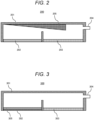
- FIG. 2 is a diagram schematically illustrating the photocatalytic decomposition apparatus according to a second embodiment.
- FIG. 2 illustrates a casing 201 of a photocatalytic decomposition apparatus 200 and an internal structure of the photocatalytic decomposition apparatus 200.
- an inclined portion 205 that is inclined in a lateral direction is provided on an upper surface of the casing 201, steam generated by a steam generator 202 moves along the inclined portion 205 so as to be cooled and become fresh water, which is introduced into a photocatalytic decomposer 203.
- the fresh water introduced in the photocatalytic decomposer 203 is decomposed by a photocatalytic reaction in a similar manner to steam.
- FIG. 3 is a diagram schematically illustrating the photocatalytic decomposition apparatus according to a third embodiment.
- FIG. 3 illustrates a casing 301 of a photocatalytic decomposition apparatus 300 and an internal structure of the photocatalytic decomposition apparatus 300.
- a blackbody portion 305 that absorbs light supplied from a light source so as to increase in temperature is provided on an upper surface of a steam generator 302.
- the blackbody portion 305 is made of a material that absorbs more heat than the steam generator 302. In this configuration, it is possible to efficiently heat water from the water layer, and to more efficiently perform photocatalytic decomposition in the overall apparatus than in the first embodiment.
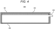
- FIG. 4 is a diagram schematically illustrating the photocatalytic decomposition apparatus according to a fourth embodiment.
- FIG. 4 illustrates a casing 401 of a photocatalytic decomposition apparatus 400 and an internal structure of the photocatalytic decomposition apparatus 400.
- a photocatalytic decomposer 403 is provided in contact with a surface on which light from the casing 401 is incident.
- a substrate holding a photocatalyst is made of a material through which at least infrared light is transmitted.
- the infrared light transmitted through the photocatalytic decomposer 403 is absorbed by a steam generator 402 and raises the temperature of the steam generator 402.
- Ultraviolet light and visible light that are not transmitted through the photocatalytic decomposer 403 are absorbed by a photocatalytic material of the photocatalytic decomposer 403, and are used for a photocatalytic reaction and contribute to water decomposition.
- the present invention is not limited to the examples described above, and includes various modification examples.
- the examples described above have been described in detail to simply describe the present invention, and are not necessarily required to include all the described configurations.
- part of the configuration of one example can be replaced with the configurations of other examples, and in addition, the configuration of the one example can also be added with the configurations of other examples.
- part of the configuration of each of the examples can be subjected to addition, deletion, and replacement with respect to other configurations.
- 100, 200, 300, 400 photocatalytic decomposition apparatus, 101, 201, 301, 401: casing, 102, 202, 302, 402: steam generator, 103, 203, 303, 403: photocatalytic decomposer, 104: collection port, 105: light, 106: steam, 107: water layer, 108: pipe, 109a, 109b: pump, 110: exhaust gas, 120: pore, 205: inclined portion, 305: blackbody portion
Landscapes
- Chemical & Material Sciences (AREA)
- Organic Chemistry (AREA)
- Chemical Kinetics & Catalysis (AREA)
- Health & Medical Sciences (AREA)
- Inorganic Chemistry (AREA)
- Engineering & Computer Science (AREA)
- General Health & Medical Sciences (AREA)
- Water Supply & Treatment (AREA)
- Electromagnetism (AREA)
- Physics & Mathematics (AREA)
- Life Sciences & Earth Sciences (AREA)
- Toxicology (AREA)
- Environmental & Geological Engineering (AREA)
- Combustion & Propulsion (AREA)
- Hydrology & Water Resources (AREA)
- Catalysts (AREA)
- Physical Water Treatments (AREA)
Abstract
Description
- The present invention relates to a photocatalytic decomposition apparatus.
- In recent years, an artificial photosynthesis system can use solar energy to synthesize compounds that can be used as other energy carriers, such as hydrogen, without emitting CO2, and thus attracts attention as a method for generating clean energy. One of methods for sustainably generating hydrogen or the like is a method using renewable energy such as sunlight, and seawater that is not being effectively used.
- As an example of such techniques, for example, there is
WO2004/085306 .WO2004/085306 discloses a water photolysis apparatus including a casing 1 having a light transmission window 12 through which sunlight L is transmitted, and a photolysis layer 5 disposed in the casing 1. A configuration is disclosed in which the photolysis apparatus is disposed in a state of floating on a water layer 9, water vapor evaporates from the water layer 9 due to irradiation with the sunlight L and is introduced into the photolysis layer 5, photocatalyst particles 52 are excited by the sunlight L in the photolysis layer 5, and the introduced water vapor is decomposed into hydrogen and oxygen in the photolysis layer 5. According to the configuration disclosed inWO2004/085306 , it is possible to efficiently obtain hydrogen and oxygen by suppressing a reverse reaction, and to provide a water photolysis apparatus that can promote the photolysis of water by effectively using solar energy. - In the conventional artificial photosynthesis system, when seawater is decomposed directly, chloride ions contained in seawater are discharged as hypochlorous acid and toxic chlorine gas, which may lead to corrosion and degradation of the apparatus and environmental pollution.
- In addition, although chloride ions can be removed by vaporizing seawater once, a mechanism for efficiently supplying seawater to the apparatus and efficiently vaporizing the seawater at the time of the removal is required. Under such circumstances, it has been desired to consider a configuration for supplying and vaporizing seawater more efficiently than conventional techniques such as the above-described
WO2004/085306 . - In view of the above-described circumstances, an object of the present invention is to provide a photocatalytic decomposition apparatus capable of efficiently supplying and vaporizing water to be decomposed by using a photocatalyst.
- To solve the above-described problems, according to an aspect of the present invention, a photocatalytic decomposition apparatus that decomposes water using a photocatalyst includes a steam generator that has a pore for sucking up water and absorbs light supplied form a light source so as to generate heat, and a photocatalytic decomposer in which steam generated by the steam generator comes in contact with the photocatalyst, and the photocatalyst is irradiated with the light supplied from the light source.
- More specific configurations according to the present invention are described in claims.
- According to the present invention, it is possible to provide a photocatalytic decomposition apparatus capable of efficiently supplying and vaporizing water to be decomposed by using a photocatalyst.
- Problems, configurations, and effects other than those described above will be clarified by the description of the following embodiments.
-
-
FIG. 1A is a diagram schematically illustrating a photocatalytic decomposition apparatus according to a first embodiment. -
FIG. 1B is an enlarged diagram illustrating a steam generator illustrated inFIG. 1A . -
FIG. 2 is a diagram schematically illustrating a photocatalytic decomposition apparatus according to a second embodiment. -
FIG. 3 is a diagram schematically illustrating a photocatalytic decomposition apparatus according to a third embodiment. -
FIG. 4 is a diagram schematically illustrating a photocatalytic decomposition apparatus according to a fourth embodiment. - A configuration according to the present invention is described below in detail with reference to the accompanying drawings.
-
FIG. 1A is a diagram schematically illustrating the photocatalytic decomposition apparatus according to a first embodiment. As illustrated inFIG. 1A , aphotocatalytic decomposition apparatus 100 according to the present embodiment includes asteam generator 102 that absorbslight 105 supplied from a light source to generate heat and generatessteam 106 from water obtained from awater layer 107, aphotocatalytic decomposer 103 that includes a photocatalyst and causes thelight 105 supplied from the light source and thesteam 106 generated by thesteam generator 102 to react with the photocatalyst so as to decompose thesteam 106, and acasing 101 housing thesteam generator 102 and thephotocatalytic decomposer 103. In the present embodiment, the sun is used as the light source, and seawater is used as thewater layer 107. Each configuration is described below in detail. - The
casing 101 is made of a material through which thelight 105 incident from the light source such as the sun is transmitted. -
FIG. 1B is an enlarged diagram illustrating the steam generator illustrated inFIG. 1A . As illustrated inFIG. 1B , thesteam generator 102 is made of a material having a large number of pores (pores penetrating in thesteam generator 102 from an upper end of thesteam generator 102 to a lower end of the steam generator 102), and can efficiently suck up water in a direction indicated by black arrows inFIG. 1B from thewater layer 107 by a capillary action of thepores 120. In addition, thesteam generator 102 can generate heat by thelight 105, and efficiently vaporize water sucked up from thewater layer 107 and remaining on the surface of thesteam generator 102. - The
steam generator 102 is preferably made of, for example, a carbon-based material such as graphite, graphene, or a carbon nanotube. - It is desirable that the porosity (the volume ratio of the pores in the steam generator 102) of the
steam generator 102 is 10% by volume or higher and 90% by volume or lower. When the porosity is lower than 10%, it is difficult to form pores penetrating from the upper end to the lower end of thesteam generator 102, and it is not possible to suck up water to be efficiently supplied to thephotocatalytic decomposer 103. On the other hand, when the porosity is higher than 90%, it is difficult to sustainably decompose water due to insufficient strength and damage. - The
photocatalytic decomposer 103 contains a photocatalyst material and decomposes steam generated by thesteam generator 102 and water liquefied by cooling steam into hydrogen (H2) and oxygen (O2) by thelight 105 and the photocatalyst. - The material of the photocatalyst is not particularly limited as long as the material of the photocatalyst absorbs light to excite electrons. Examples of the material of the photocatalyst are TiO2, SrTiO3, SrTiO2N, BaTaO2N, NaTaO3, WO3, ZnO, Fe2O3, CuO, Ta2O5, Bi2O3, SnO2, BiVO4, and Y2Ti2O5S2. In order to promote the reaction, a material that can serve as a promoter may be appropriately modified on the surface of the material of the photocatalyst. Representative examples of the material of the promoter are Pt, Ru, Rh, and Au. In addition, the material of the photocatalyst may be supported by a substrate. Furthermore, the material of the photocatalyst may be a mixture of powders functioning as an anode and a cathode or may be a pressed powder or a sheet.
Furthermore, a photoelectrode structure in which an anode portion and a cathode portion are separated may be used. - The gases (generated gases: H2 and O2) generated by the
photocatalytic decomposer 103 can be collected through acollection port 104. Although not illustrated, a mechanism capable of trapping extra steam, for example, a mechanism such as a Liebig condenser, may be provided at an edge of thecollection port 104. A mechanism is preferably provided, which transfers the generated gases in apipe 108 by apump 109a, separates a gas other than H2 and O2, discharges anexhaust gas 110, and separates the gases into H2 and O2 using apump 109b after the trapping of the steam. Furthermore, a mechanism is preferably provided, which uses trapped fresh water to remove salt partially precipitated in thesteam generator 102. - According to the
photocatalytic decomposition apparatus 100 according to the present embodiment, in thesteam generator 102 having thepores 120, thelight 105 is converted into heat, water is vaporized into steam, and water decomposition is performed by thephotocatalytic decomposer 103 on the steam or fresh water generated by cooling the steam. Therefore, it is possible to more efficiently decompose water in thephotocatalytic decomposition apparatus 100 than the conventional techniques. Water in thewater layer 107 is vaporized once before being decomposed in thephotocatalytic decomposer 103. Therefore, for example, in a case where the water is seawater, it is possible to suppress the generation of chloride ions and hypochlorous acid in thephotocatalytic decomposer 103, and to sustainably decompose seawater without generating harmful and toxic substances contained in the seawater. - The
photocatalytic decomposition apparatus 100 according to the present embodiment is not limited to only the use in decomposing water to generate only H2 and O2. For example, CO2 or nitrogen oxide (NOx) may be introduced and used for reduction reaction at a cathode portion. In this case, the gaseous species to be reacted can be introduced into a container by providing a separate gas introduction portion. In addition, the gaseous species can be used for synthesis of organic compounds such as formic acid, ethanol, methanol, and methyl. -
FIG. 2 is a diagram schematically illustrating the photocatalytic decomposition apparatus according to a second embodiment.FIG. 2 illustrates acasing 201 of aphotocatalytic decomposition apparatus 200 and an internal structure of thephotocatalytic decomposition apparatus 200. As illustrated inFIG. 2 , in the present embodiment, aninclined portion 205 that is inclined in a lateral direction is provided on an upper surface of thecasing 201, steam generated by asteam generator 202 moves along theinclined portion 205 so as to be cooled and become fresh water, which is introduced into aphotocatalytic decomposer 203. The fresh water introduced in thephotocatalytic decomposer 203 is decomposed by a photocatalytic reaction in a similar manner to steam. - With this configuration, it is possible to more efficiently supply water to be decomposed than the supply of steam to the
photocatalytic decomposer 203, and to more efficiently perform photocatalytic decomposition in the overall apparatus than in the first embodiment. -
FIG. 3 is a diagram schematically illustrating the photocatalytic decomposition apparatus according to a third embodiment.FIG. 3 illustrates acasing 301 of aphotocatalytic decomposition apparatus 300 and an internal structure of thephotocatalytic decomposition apparatus 300. As illustrated inFIG. 3 , in the present embodiment, ablackbody portion 305 that absorbs light supplied from a light source so as to increase in temperature is provided on an upper surface of asteam generator 302. Theblackbody portion 305 is made of a material that absorbs more heat than thesteam generator 302. In this configuration, it is possible to efficiently heat water from the water layer, and to more efficiently perform photocatalytic decomposition in the overall apparatus than in the first embodiment. -
FIG. 4 is a diagram schematically illustrating the photocatalytic decomposition apparatus according to a fourth embodiment.FIG. 4 illustrates acasing 401 of aphotocatalytic decomposition apparatus 400 and an internal structure of thephotocatalytic decomposition apparatus 400. As illustrated inFIG. 4 , in the present embodiment, aphotocatalytic decomposer 403 is provided in contact with a surface on which light from thecasing 401 is incident. In thephotocatalytic decomposer 403, a substrate holding a photocatalyst is made of a material through which at least infrared light is transmitted. The infrared light transmitted through thephotocatalytic decomposer 403 is absorbed by asteam generator 402 and raises the temperature of thesteam generator 402. Ultraviolet light and visible light that are not transmitted through thephotocatalytic decomposer 403 are absorbed by a photocatalytic material of thephotocatalytic decomposer 403, and are used for a photocatalytic reaction and contribute to water decomposition. - In this configuration, it is possible to more efficiently generate heat and decompose water by dividing light from the light source into light for heating water and light for exciting the photocatalyst, and to more efficiently perform photocatalytic decomposition in the overall apparatus than in the first embodiment.
- As described above, according to the present invention, it is shown that it is possible to provide a photocatalytic decomposition apparatus capable of efficiently supplying and vaporizing water to be decomposed by using a photocatalyst.
- It should be noted that the present invention is not limited to the examples described above, and includes various modification examples. For example, the examples described above have been described in detail to simply describe the present invention, and are not necessarily required to include all the described configurations. In addition, part of the configuration of one example can be replaced with the configurations of other examples, and in addition, the configuration of the one example can also be added with the configurations of other examples. In addition, part of the configuration of each of the examples can be subjected to addition, deletion, and replacement with respect to other configurations.
- 100, 200, 300, 400: photocatalytic decomposition apparatus, 101, 201, 301, 401: casing, 102, 202, 302, 402: steam generator, 103, 203, 303, 403: photocatalytic decomposer, 104: collection port, 105: light, 106: steam, 107: water layer, 108: pipe, 109a, 109b: pump, 110: exhaust gas, 120: pore, 205: inclined portion, 305: blackbody portion
Claims (6)
- A photocatalytic decomposition apparatus that uses a photocatalyst, the photocatalytic decomposition apparatus comprising:a steam generator that has a pore for sucking up water and absorbs light supplied from a light source so as to generate heat; anda photocatalytic decomposer in which steam generated by the steam generator comes into contact with the photocatalyst, and the photocatalyst is irradiated with the light supplied from the light source.
- The photocatalytic decomposition apparatus according to claim 1, wherein the steam generator is in contact with water, and the pore sucks up water by a capillary action.
- The photocatalytic decomposition apparatus according to claim 1, wherein a porosity of the steam generator is 10% by volume or higher and 90% by volume or lower.
- The photocatalytic decomposition apparatus according to claim 1, whereinan inclined portion is provided on an inner surface of a casing housing the steam generator and the photocatalytic decomposer, andsteam generated by the steam generator or water moves along the inclined portion and is supplied to the photocatalytic decomposer.
- The photocatalytic decomposition apparatus according to claim 1, further comprising a blackbody portion that is provided on an upper surface of the steam generator and absorbs more heat than the steam generator.
- The photocatalytic decomposition apparatus according to claim 1, wherein the photocatalytic decomposer is provided on a surface on which the light from the casing is incident, and the light transmitted through the photocatalytic decomposer is supplied to the steam generator.
Applications Claiming Priority (1)
| Application Number | Priority Date | Filing Date | Title |
|---|---|---|---|
| JP2022157805A JP2024051568A (en) | 2022-09-30 | 2022-09-30 | Photocatalytic decomposition device |
Publications (1)
| Publication Number | Publication Date |
|---|---|
| EP4353688A1 true EP4353688A1 (en) | 2024-04-17 |
Family
ID=88192126
Family Applications (1)
| Application Number | Title | Priority Date | Filing Date |
|---|---|---|---|
| EP23199340.3A Pending EP4353688A1 (en) | 2022-09-30 | 2023-09-25 | Photocatalytic decomposition apparatus |
Country Status (2)
| Country | Link |
|---|---|
| EP (1) | EP4353688A1 (en) |
| JP (1) | JP2024051568A (en) |
Citations (5)
| Publication number | Priority date | Publication date | Assignee | Title |
|---|---|---|---|---|
| FR2833000B1 (en) * | 2001-12-04 | 2004-01-02 | Navarre Francois Pierre | TECHNICAL KIT FOR PURIFYING AQUEOUS LIQUIDS LOADED WITH IMPURITIES |
| WO2004085306A1 (en) | 2003-03-26 | 2004-10-07 | Matsushita Electric Industrial Co. Ltd. | Apparatus for photolysis of water and method for photolysis of water |
| FR2856052B1 (en) * | 2003-06-11 | 2006-05-19 | Francois Pierre Navarre | DEVICE FOR PURIFYING RICH MICRO POLLUTANT WATER |
| WO2021242705A1 (en) * | 2020-05-24 | 2021-12-02 | Matregenix, Inc. | System and method for solar-powered desalination and water purification |
| CN114873677A (en) * | 2022-05-18 | 2022-08-09 | 西安交通大学 | Solar photo-thermal conversion water treatment method and device for resisting salt deposition |
Family Cites Families (1)
| Publication number | Priority date | Publication date | Assignee | Title |
|---|---|---|---|---|
| JPS5534141A (en) * | 1978-08-31 | 1980-03-10 | Toyobo Co Ltd | Evaporating and concentrating method by solar heat |
-
2022
- 2022-09-30 JP JP2022157805A patent/JP2024051568A/en active Pending
-
2023
- 2023-09-25 EP EP23199340.3A patent/EP4353688A1/en active Pending
Patent Citations (5)
| Publication number | Priority date | Publication date | Assignee | Title |
|---|---|---|---|---|
| FR2833000B1 (en) * | 2001-12-04 | 2004-01-02 | Navarre Francois Pierre | TECHNICAL KIT FOR PURIFYING AQUEOUS LIQUIDS LOADED WITH IMPURITIES |
| WO2004085306A1 (en) | 2003-03-26 | 2004-10-07 | Matsushita Electric Industrial Co. Ltd. | Apparatus for photolysis of water and method for photolysis of water |
| FR2856052B1 (en) * | 2003-06-11 | 2006-05-19 | Francois Pierre Navarre | DEVICE FOR PURIFYING RICH MICRO POLLUTANT WATER |
| WO2021242705A1 (en) * | 2020-05-24 | 2021-12-02 | Matregenix, Inc. | System and method for solar-powered desalination and water purification |
| CN114873677A (en) * | 2022-05-18 | 2022-08-09 | 西安交通大学 | Solar photo-thermal conversion water treatment method and device for resisting salt deposition |
Also Published As
| Publication number | Publication date |
|---|---|
| JP2024051568A (en) | 2024-04-11 |
Similar Documents
| Publication | Publication Date | Title |
|---|---|---|
| Cho et al. | Improved photoelectrochemical properties of TiO2 nanotubes doped with Er and effects on hydrogen production from water splitting | |
| Yang et al. | Self-assembly Cu2O nanowire arrays on Cu mesh: a solid-state, highly-efficient, and stable photocatalyst for toluene degradation under sunlight | |
| Liu et al. | A porous Ni 3 N nanosheet array as a high-performance non-noble-metal catalyst for urea-assisted electrochemical hydrogen production | |
| Wang et al. | Photocatalytic water oxidation on BiVO4 with the electrocatalyst as an oxidation cocatalyst: essential relations between electrocatalyst and photocatalyst | |
| Ma et al. | Hydrazine-assisted electrolytic hydrogen production: CoS 2 nanoarray as a superior bifunctional electrocatalyst | |
| ES2670972T3 (en) | Reduction of carbon dioxide in products with an indium oxide electrode | |
| JP5830527B2 (en) | Semiconductor device, hydrogen production system, and methane or methanol production system | |
| Ren et al. | Continuous production of ethylene from carbon dioxide and water using intermittent sunlight | |
| Wang et al. | Efficient gas phase VOC removal and electricity generation in an integrated bio-photo-electro-catalytic reactor with bio-anode and TiO2 photo-electro-catalytic air cathode | |
| Sun et al. | Synergistic enhancement of H2 and CH4 evolution by CO2 photoreduction in water with reduced graphene oxide–bismuth monoxide quantum dot catalyst | |
| CN109569684B (en) | Plasma-modified metal oxide and g-carbon nitride co-modified titania nanorod composite photocatalyst and its preparation and application | |
| WO2009048242A2 (en) | Plasma decomposition apparatus and method for carbon dioxide | |
| de Brito et al. | Turning carbon dioxide into fuel concomitantly to the photoanode-driven process of organic pollutant degradation by photoelectrocatalysis | |
| CN112076761A (en) | A copper oxide nanowire-supported silver particle composite electrode, preparation method and application | |
| Li et al. | A minireview on electrochemical CO 2 conversion based on carbonate/bicarbonate media | |
| JP5398918B2 (en) | Photocatalytic material for decomposing carbon oxides | |
| KR101814128B1 (en) | manufacturing method of hydrogen using liquid phase plasma and photocatalysts | |
| CN113353932A (en) | Hierarchical pore charcoal electrocatalyst prepared from pitaya peel and preparation method and application thereof | |
| ES2744877T3 (en) | Device for the production of hydrogen and electricity | |
| Pouramini et al. | Enhancing PFC ability to dye removal and power generation simultaneously via conductive spheres in the anodic chamber | |
| US20140154597A1 (en) | Fuel Cells Based on Precise Energy Separation | |
| EP4353688A1 (en) | Photocatalytic decomposition apparatus | |
| JP6497590B2 (en) | Method of decomposing water, water splitting device and anode electrode for oxygen generation | |
| US20240139723A1 (en) | Photocatalyst decomposition system | |
| CN112827484A (en) | A kind of preparation of composite photoelectric catalytic material and method for treating unsymmetrical dimethyl hydrazine wastewater |
Legal Events
| Date | Code | Title | Description |
|---|---|---|---|
| PUAI | Public reference made under article 153(3) epc to a published international application that has entered the european phase |
Free format text: ORIGINAL CODE: 0009012 |
|
| STAA | Information on the status of an ep patent application or granted ep patent |
Free format text: STATUS: REQUEST FOR EXAMINATION WAS MADE |
|
| 17P | Request for examination filed |
Effective date: 20230925 |
|
| AK | Designated contracting states |
Kind code of ref document: A1 Designated state(s): AL AT BE BG CH CY CZ DE DK EE ES FI FR GB GR HR HU IE IS IT LI LT LU LV MC ME MK MT NL NO PL PT RO RS SE SI SK SM TR |
|
| REG | Reference to a national code |
Ref country code: DE Ref legal event code: R079 Free format text: PREVIOUS MAIN CLASS: C02F0001720000 Ipc: B01J0004000000 |
|
| RIC1 | Information provided on ipc code assigned before grant |
Ipc: B01J 4/00 20060101AFI20260227BHEP Ipc: B01J 7/00 20060101ALI20260227BHEP Ipc: B01J 19/12 20060101ALI20260227BHEP Ipc: C01B 3/042 20260101ALI20260227BHEP Ipc: C01B 13/02 20060101ALI20260227BHEP Ipc: C02F 1/02 20230101ALI20260227BHEP |
|
| GRAP | Despatch of communication of intention to grant a patent |
Free format text: ORIGINAL CODE: EPIDOSNIGR1 |
|
| STAA | Information on the status of an ep patent application or granted ep patent |
Free format text: STATUS: GRANT OF PATENT IS INTENDED |