EP4353578A1 - Verankerungssystem und verankerungsverfahren - Google Patents
Verankerungssystem und verankerungsverfahren Download PDFInfo
- Publication number
- EP4353578A1 EP4353578A1 EP22807284.9A EP22807284A EP4353578A1 EP 4353578 A1 EP4353578 A1 EP 4353578A1 EP 22807284 A EP22807284 A EP 22807284A EP 4353578 A1 EP4353578 A1 EP 4353578A1
- Authority
- EP
- European Patent Office
- Prior art keywords
- mooring
- unmanned machine
- rope
- mooring rope
- bit
- Prior art date
- Legal status (The legal status is an assumption and is not a legal conclusion. Google has not performed a legal analysis and makes no representation as to the accuracy of the status listed.)
- Withdrawn
Links
Images




Classifications
-
- B—PERFORMING OPERATIONS; TRANSPORTING
- B63—SHIPS OR OTHER WATERBORNE VESSELS; RELATED EQUIPMENT
- B63B—SHIPS OR OTHER WATERBORNE VESSELS; EQUIPMENT FOR SHIPPING
- B63B21/00—Tying-up; Shifting, towing, or pushing equipment; Anchoring
- B63B21/04—Fastening or guiding equipment for chains, ropes, hawsers, or the like
-
- B—PERFORMING OPERATIONS; TRANSPORTING
- B63—SHIPS OR OTHER WATERBORNE VESSELS; RELATED EQUIPMENT
- B63B—SHIPS OR OTHER WATERBORNE VESSELS; EQUIPMENT FOR SHIPPING
- B63B21/00—Tying-up; Shifting, towing, or pushing equipment; Anchoring
- B63B21/16—Tying-up; Shifting, towing, or pushing equipment; Anchoring using winches
-
- B—PERFORMING OPERATIONS; TRANSPORTING
- B63—SHIPS OR OTHER WATERBORNE VESSELS; RELATED EQUIPMENT
- B63B—SHIPS OR OTHER WATERBORNE VESSELS; EQUIPMENT FOR SHIPPING
- B63B35/00—Vessels or similar floating structures specially adapted for specific purposes and not otherwise provided for
- B63B35/44—Floating buildings, stores, drilling platforms, or workshops, e.g. carrying water-oil separating devices
-
- B—PERFORMING OPERATIONS; TRANSPORTING
- B64—AIRCRAFT; AVIATION; COSMONAUTICS
- B64U—UNMANNED AERIAL VEHICLES [UAV]; EQUIPMENT THEREFOR
- B64U10/00—Type of UAV
- B64U10/60—Tethered aircraft
-
- B—PERFORMING OPERATIONS; TRANSPORTING
- B64—AIRCRAFT; AVIATION; COSMONAUTICS
- B64U—UNMANNED AERIAL VEHICLES [UAV]; EQUIPMENT THEREFOR
- B64U10/00—Type of UAV
- B64U10/10—Rotorcrafts
- B64U10/13—Flying platforms
-
- B—PERFORMING OPERATIONS; TRANSPORTING
- B64—AIRCRAFT; AVIATION; COSMONAUTICS
- B64U—UNMANNED AERIAL VEHICLES [UAV]; EQUIPMENT THEREFOR
- B64U2101/00—UAVs specially adapted for particular uses or applications
- B64U2101/15—UAVs specially adapted for particular uses or applications for conventional or electronic warfare
- B64U2101/16—UAVs specially adapted for particular uses or applications for conventional or electronic warfare for controlling, capturing or immobilising other vehicles
-
- B—PERFORMING OPERATIONS; TRANSPORTING
- B64—AIRCRAFT; AVIATION; COSMONAUTICS
- B64U—UNMANNED AERIAL VEHICLES [UAV]; EQUIPMENT THEREFOR
- B64U2101/00—UAVs specially adapted for particular uses or applications
- B64U2101/30—UAVs specially adapted for particular uses or applications for imaging, photography or videography
-
- B—PERFORMING OPERATIONS; TRANSPORTING
- B64—AIRCRAFT; AVIATION; COSMONAUTICS
- B64U—UNMANNED AERIAL VEHICLES [UAV]; EQUIPMENT THEREFOR
- B64U2101/00—UAVs specially adapted for particular uses or applications
- B64U2101/60—UAVs specially adapted for particular uses or applications for transporting passengers; for transporting goods other than weapons
-
- B—PERFORMING OPERATIONS; TRANSPORTING
- B64—AIRCRAFT; AVIATION; COSMONAUTICS
- B64U—UNMANNED AERIAL VEHICLES [UAV]; EQUIPMENT THEREFOR
- B64U2201/00—UAVs characterised by their flight controls
- B64U2201/20—Remote controls
Definitions
- the present disclosure relates to a mooring system and a mooring method each of which moors a floating structure, such as a ship, to a mooring facility, such as a quay.
- a conventional mooring work of mooring a ship to a quay through a ship mooring rope has been performed by cooperation of a land-side worker and a ship-side worker.
- the conventional mooring work is performed by the following procedure. First, the ship-side worker unwinds the ship mooring rope from a hawser drum mounted on the ship and throws a heaving line, tied to a tip of the ship mooring rope, toward the quay. Next, the land-side worker pulls the heaving line to draw the ship mooring rope and fixes one end of the ship mooring rope to a ship mooring bit located at the quay. Finally, the ship mooring rope is wound by the hawser drum mounted on the ship. Thus, tensile force is applied to the ship mooring rope, and the ship is moored to the quay.
- PTL 1 proposes that an end portion of a mooring rope connected to a first connector is carried to a second connector by using an unmanned machine (aerial drone, amphibious drone).
- PTL 1 discloses: a case where the first connector is located at the ship, and the second connector is located at the quay; a case where the first connector is located at the quay, and the second connector is located at the ship; and a case where the first connector and the second connector are located at the ship.
- PTL 1 describes that the unmanned machine carries the tip of the mooring rope and can fix and unfix the tip of the mooring rope to and from the second connector (ship mooring bit, for example), but does not disclose a specific configuration of the unmanned machine.
- the unmanned machine may be able to hang the tip of the mooring rope to the second connector.
- the control of the unmanned machine requires a high degree of positional accuracy. Therefore, this is not realistic from the viewpoint of work efficiency.
- the present disclosure was made under these circumstances, and an object of the present disclosure is to propose a mooring system that moors and unmoors a floating body, such as a ship, to and from a mooring bit located at a quay or the like and can realize manpower saving in mooring and unmooring work.
- a mooring system is a mooring system that moors a floating structure to a mooring facility, one of the floating structure and the mooring facility being a first object, the other being a second object.
- the mooring system includes:
- a mooring method is a mooring method of mooring a floating structure to a mooring facility, one of the floating structure and the mooring facility being a first object, the other being a second object.
- the mooring method includes:
- the present disclosure can propose the mooring system that moors and unmoors the floating body, such as a ship, to and from the mooring bit located at a quay or the like and can realize manpower saving in mooring and unmooring work.
- FIG. 1 is a plan view showing that a floating structure 10 is moored to a mooring facility 11 by a mooring system 1 according to Embodiment 1 of the present disclosure.
- the mooring system 1 is located at the floating structure 10, and a mooring bit 12 is located at the mooring facility 11.
- the mooring system 1 may be located at the mooring facility 11, and the mooring bit 12 may be located at the floating structure 10.
- Some of components of the mooring system 1 may be located at the floating structure 10, and the rest of the components of the mooring system 1 may be located at the mooring facility 11 or another structure (small ship, for example).
- the floating structure 10 is the boat-shaped floating structure 10 (i.e., a ship).
- the floating structure 10 is not limited to the ship and may be a structure, such as an ocean platform (a floating body production facility or a floating body storage facility), floating on the ocean.
- the mooring facility 11 according to the present embodiment is a quay at a port.
- the mooring facility 11 is not limited to the quay and may be a ship other than the floating structure 10, a mooring floating body, a floating body production facility, or the like.
- the floating structure 10 includes: a vessel 5; at least one propeller 2 that outputs thrust in a front-rear direction with respect to the vessel 5; and at least one side thruster 3 that outputs thrust in a lateral direction with respect to the vessel 5.
- a horizontal direction connecting a bow and stern of the vessel 5 is referred to as the "front-rear direction" of the vessel 5
- a horizontal direction (left-right direction) orthogonal to the front-rear direction is referred to as the "lateral direction” of the vessel 5.
- the floating structure 10 may not include any propellers or thrusters and may be moved by being towed.
- the floating structure 10 includes at least one mooring system 1.
- the mooring systems 1 are located at four positions of the vessel 5 which are separated from each other in the front-rear direction.
- the number of mooring systems 1 located at the floating structure 10 is not limited to the present embodiment.
- FIG. 2 is a schematic configuration diagram of the mooring system 1.
- the mooring system 1 includes: a mooring rope 20; a winch 30 that can wind and unwind the mooring rope 20; a locking tool 24; at least one conveyance unmanned machine (hereinafter simply referred to as an "unmanned machine 6") that conveys the mooring rope 20; and a control device 60.
- the unmanned machine 6 may be shared by the mooring systems 1.
- the unmanned machine 6 is located at the floating structure 10.
- the unmanned machine 6 may be located at the mooring facility 11.
- the control device 60 is located at the floating structure 10.
- the control device 60 may be located at the mooring facility 11 or may be located at a small ship independent from the floating structure 10.
- FIG. 3 is a schematic configuration diagram of the winch 30.
- the winch 30 shown in FIG. 3 includes: a hawser drum 31 around which the mooring rope 20 is wound; a motor 32 that rotates the hawser drum 31; a hydraulic clutch 33 that switches between a state where power transmission from the motor 32 to the hawser drum 31 is established and a state where such power transmission is cut; a reduction gear 34 located on a power transmitting path extending from the motor 32 to the hawser drum 31; and a brake 35 that applies braking force at all times.
- the winch 30 according to the present embodiment is of an electrohydraulic type. However, the structure of the winch 30 is not limited to the above, and the winch 30 may be of an electric type.
- the power transmitting path extending from the motor 32 to the hawser drum 31 is established by the clutch 33, and the hawser drum 31 is rotated in a winding direction.
- the clutch 33 is disengaged, and the power transmitting path extending from the motor 32 to the hawser drum 31 is cut.
- the hawser drum 31 becomes a state of being able to idle and can rotate in an unwinding direction.
- the power transmitting path extending from the motor 32 to the hawser drum 31 may be established by the clutch 33, and the hawser drum 31 may be rotated in the unwinding direction.
- the mooring rope 20 unwound from the hawser drum 31 is protected and guided by a suitable mooring rope guide 23, such as a chock (mooring hole), a fair-leader, a deck end roller, or a stand roller.
- the mooring system 1 further includes a rotational position sensor 51, a tensile force sensor 26, a rope length measuring device 53, and a winch control device 50 configured to control the operation of the winch 30 based on detected values of the rotational position sensor 51, the tensile force sensor 26, and the rope length measuring device 53.
- the rotational position sensor 51 detects a rotational position and rotational frequency of the motor 32 or the hawser drum 31.
- the rope length measuring device 53 measures the length of the mooring rope 20 which has been unwound from the hawser drum 31.
- the winch control device 50 measures the rotation of the motor 32 or the hawser drum 31 and estimates the length of the wound mooring rope 20 and the length of the unwound mooring rope 20 based on a detection signal of the rotational position sensor 51 and/or a measured value of the rope length measuring device 53.
- the locking tool 24 locks a tip of the mooring rope 20 such that the tip of the mooring rope 20 is engageable with and disengageable from the locking tool 24.
- the locking tool 24 is located at the floating structure 10.
- the locking tool 24 is located at a position, such as a position on a deck, a side surface of the vessel 5, or a support base of the hawser drum 31 of the mooring system 1, which is appropriate for the route of the mooring rope 20.
- the engagement the mooring rope 20 with the locking tool 24 and the disengagement of the mooring rope 20 from the locking tool 24 may be performed by a worker. Or, the engagement of the mooring rope 20 with the locking tool 24 may be performed by the worker, and the disengagement of the mooring rope 20 from the locking tool 24 may be performed automatically.
- the locking tool 24 may have an automatic release function of automatically releasing the mooring rope 20.
- the locking tool 24 includes an actuator that performs a disengaging operation, and when the actuator operates upon reception of a disengaging signal from an operating unit (not shown), the mooring rope 20 is disengaged from the locking tool 24.
- the locking tool 24 includes a tensile force buffer 27.
- the tensile force buffer 27 includes a buffer member, such as a spring. When unexpected excessive tensile force is applied to the mooring rope 20 engaged with the locking tool 24, the tensile force buffer 27 absorbs the tensile force to prevent the rupture of the mooring rope 20 and the damage of the locking tool 24 or the structure to which the locking tool 24 is fixed.
- the locking tool 24 includes the tensile force sensor 26.
- the tensile force sensor 26 is, for example, a load cell, and the tensile force of the mooring rope 20 can be estimated based on a load detected by the load cell.
- the winch control device 50 controls the rotation of the hawser drum 31 based on the detected value of the tensile force sensor 26 such that the tensile force acting on the mooring rope 20 is maintained at a predetermined value that does not exceed a predetermined upper limit.
- the unmanned machine 6 moves the mooring rope 20 from the floating structure 10 to the mooring bit 12.
- the unmanned machine 6 may be able to move between the floating structure 10 and the mooring facility 11 and may travel on the sea, on land, or in the sky.
- Examples of the unmanned machine 6 include: an unmanned aircraft, such as a drone; and an amphibious unmanned machine, such as an amphibious drone.
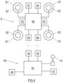
- FIG. 4 is a diagram showing a schematic configuration of the unmanned machine 6.
- the unmanned machine 6 includes pairs of rotors 61 and motors 62, a battery 63, sensors 64, a transmitter 65, a receiver 66, a camera 67, and a controller 68.
- the motor 62 rotates the rotor 61.
- the battery 63 supplies electric power to the motor 62.
- an engine may be mounted.
- the sensors 64 include at least one type of detector that detects a flying angle, flying speed, and positional information (GPS positional information) of the unmanned machine 6.
- GPS positional information positional information
- the configuration of the unmanned machine 6 is not limited to the present embodiment, and the unmanned machine 6 may fly and/or swim (dive) by remote control or autonomously.
- the unmanned machine 6 is controlled by the control device 60.
- the control device 60 is a manipulating device that performs remote control of the unmanned machine 6.
- the control device 60 may be a device that performs autonomous movement (autonomous flight) of the unmanned machine 6.
- the control device 60 includes an operation tool 41, a display 42, a transmitter 43, a receiver 44, a calculator 45, and a communicator 46.
- the operation tool 41 is operated by an operator or a manipulator, and information, operation, and the like are input to the calculator 45 through the operation tool 41.
- a keyboard, a lever, a button, a touch-panel-type display, and a joystick may be used as the operation tool 41.
- At least one of a display of a smartphone, a display of a tablet personal computer, a goggle display, and a head mount display may be used as the display 42.
- the transmitter 43 transmits, for example, a command signal to the unmanned machine 6.
- the receiver 44 receives an image signal, positional information, information detected by the sensors 64, and the like from the unmanned machine 6.
- the communicator 46 performs transmission and reception of information, such as weather/marine phenomenon information and positional information of the mooring bit 12, utilized in the mooring system 1.
- the calculator 45 acquires information and signals through the operation tool 41, the receiver 44, and the communicator 46, performs calculation processing, and outputs the result of the calculation processing through the display 42 and the transmitter 43.
- the calculator 45 may include a manual control program that generates and sends a command signal based on information input through the operation tool 41.
- the calculator 45 may include an automatic control program that generates and sends a command signal based on image information from the camera 67 mounted on the unmanned machine 6 such that the unmanned machine 6 performs the autonomous movement (autonomous flight) along a set route.
- the command signal sent from the transmitter 43 of the control device 60 is received by the receiver 66 of the unmanned machine 6 and sent to the controller 68.
- the controller 68 processes the command signal together with the information acquired from the sensors 64 and controls the rotational frequency of the rotor 61 driven by the motor 62.
- the controller 68 transmits image (or video image) information, taken by the camera 67, to the control device 60 through the transmitter 65.
- the control device 60 outputs the received image information to the display 42.
- the manipulator can control the unmanned machine 6 by utilizing the image information shown on the display 42.
- the unmanned machine 6 includes a holding tool 69 that holds the mooring rope 20.
- An intermediate portion of the mooring rope 20 is inserted through the holding tool 69.
- the intermediate portion of the mooring rope 20 is a portion between a tip portion locked to the locking tool 24 and a portion wound around the hawser drum 31.
- the holding tool 69 includes an annular portion into which the mooring rope 20 can be inserted.
- the mooring rope 20 is loosely inserted into the holding tool 69.
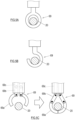
- a held position of the mooring rope 20 held by the holding tool 69 is variable. Examples of the shape of such holding tool 69 include a ring shape ( FIG. 5A ), a hook shape ( FIG. 5B ), and an open-close claw shape ( FIG. 5C ).
- the holding tool 69 ( FIG. 5C ) having the open-close claw shape includes, for example, two claws.
- Each of the claws includes: a circular-arc link 69a located at a tip of the claw; two linear links 69b and 69c connected to the circular-arc link 69a; joints each coupling the adjacent links to each other; and actuators (not shown) that drive the joints.
- the two claws can be opened and closed by the rotations of the joints.
- the mooring method roughly includes (1) a preparing step, (2) a rope hanging step, and (3) a rope tensing step.
- the rope hanging step may be performed manually or automatically.
- the tip of the mooring rope 20 is engaged with the locking tool 24, and the mooring rope 20 is unwound from the hawser drum 31 of the winch 30.
- the mooring rope 20 may be unwound in advance by a length adequate when the mooring rope 20 extends to the mooring bit 12 and returns, or may be unwound little by little in accordance with the movement of the unmanned machine 6.
- the intermediate portion of the unwound mooring rope 20 is held by the holding tool 69 of the unmanned machine 6.
- the unmanned machine 6 stands by at a stand-by position defined at the floating structure 10.
- the manipulator When manually performing the rope hanging step, the manipulator performs the remote control of the unmanned machine 6 by using the operation tool 41 connected to the control device 60.
- the unmanned machine 6 controlled by the manipulator departs from the stand-by position, moves toward the mooring bit 12, hangs the mooring rope 20 to the mooring bit 12, and returns to the stand-by position again.
- the manipulator can control the unmanned machine 6 by visually confirming the image taken by the camera 67 mounted on the unmanned machine 6 or by visually grasping a positional relation between the unmanned machine 6 and the mooring bit 12.
- the position of the mooring bit 12 as a target and the designation of the mooring system 1 including the mooring rope 20 to be hung to the mooring bit 12 are input to the control device 60 by the operator.
- the position of the mooring bit 12 as the target can be acquired from map information.
- a positional information transmitter may be located at the mooring bit 12, and the positional information of the mooring bit 12 may be sent from the positional information transmitter to the control device 60 through a communication network.
- the positional information transmitter examples include: a GPS sender that receives a radio wave from a GPS satellite, calculates positional information, and sends the positional information to the control device 60; and an IC tag that grasps positional information by utilizing a communication network and sends the positional information to the control device 60.
- a light source may be located at the mooring bit 12, and a positional information detector may calculate positional information of the mooring bit 12 by utilizing an optical sensor that detects light from the light source, and transmit the positional information to the control device 60.
- a command of starting rope hanging is input to the control device 60 by the operator.
- the control device 60 acquires the command of starting rope hanging and calculates a flight route of the unmanned machine 6.
- the control device 60 uses the weather/marine phenomenon information of the mooring facility 11, the positional information of the unmanned machine 6, the positional information of the mooring bit 12, and the like.
- the control device 60 calculates such a flight route that the unmanned machine 6 departs from the stand-by position, moves to the mooring bit 12, hangs the mooring rope 20 to the mooring bit 12, and returns to the stand-by position again. It is desirable that to suppress an influence of wind, the flight route of the unmanned machine 6 be close to a water surface.
- the control device 60 performs the automatic control of the unmanned machine 6 such that the unmanned machine 6 moves along the calculated flight route.
- the control device 60 can control the operation of the unmanned machine 6 by analyzing the image taken by the camera 67 mounted on the unmanned machine 6.
- the unmanned machine 6 moves from the stand-by position to the mooring bit 12 while holding the intermediate portion of the mooring rope 20. It is desirable that to suppress an influence of wind, the unmanned machine 6 move close to the water surface.
- the mooring rope 20 including the intermediate portion held by the unmanned machine 6 forms a relatively large loop having a length that is about twice a distance between the floating structure 10 and the mooring bit 12.
- the holding tool 69 of the unmanned machine 6 flies over the mooring bit 12 and then moves down, the loop of the mooring rope 20 is hung to the mooring bit 12 (see FIG. 6 ).
- Whether or not the mooring rope 20 is hung to the mooring bit 12 can be determined by the image taken by the camera 67 of the unmanned machine 6.
- the unmanned machine 6 releases the mooring rope 20 and then returns to the stand-by position of the floating structure 10.
- the unmanned machine 6 may return to the stand-by position of the floating structure 10 along the mooring rope 20 without releasing the mooring rope 20.
- the unmanned machine 6 can be collected even if the unmanned machine 6 becomes uncontrollable or breaks down in the middle of returning to the stand-by position of the floating structure 10 along the mooring rope 20.
- a portion of the mooring bit 12 to which the mooring rope 20 is hung may include a roller that turns.
- at least a body portion of the mooring bit 12 to which the mooring rope 20 is hung includes a pulley (or a roller) that rotates about an axis extending in a vertical direction.
- the mooring system 1 can unmoor the floating structure 10. First, the mooring rope 20 is unwound from the hawser drum 31, and the tensile force of the mooring rope 20 is adequately reduced. Next, the mooring rope 20 is disengaged from the locking tool 24. Disengaging the mooring rope 20 from the locking tool 24 may be performed manually or automatically. After the mooring rope 20 is released from the locking tool 24, the mooring rope 20 is wound around the hawser drum 31 by the operation of the winch 30. Thus, the floating structure 10 is unmoored.
- the mooring system 1 is a mooring system that moors the floating structure 10 to the mooring facility 11, one of the floating structure 10 and the mooring facility 11 being a first object, the other being a second object, the mooring system 1 including:
- the mooring method according to the present embodiment is a mooring method that moors the floating structure 10 to the mooring facility 11, one of the floating structure 10 and the mooring facility 11 being the first object, the other being the second object, the mooring method including:
- the work of hanging the mooring rope 20 to the mooring bit 12 is performed by the unmanned machine 6. Since the unmanned machine 6 hangs the intermediate portion of the mooring rope 20 to the mooring bit 12, the control of the unmanned machine 6 does not require a high degree of positional accuracy. Therefore, even when an error of the position of the unmanned machine 6 relative to the mooring bit 12 occurs due to wind or accuracy of meters, the work of hanging the mooring rope 20 to the mooring bit 12 can be stably performed. Thus, a worker who ties the mooring rope 20 to the mooring bit 12 is not required, and manpower saving can be realized.
- the number of workers who directly touch or approach the mooring rope 20 in the mooring work can be reduced.
- the floating structure 10 can be moored to the quay, and goods can be transported to a disaster-stricken area at an early stage through a sea route.
- the holding tool 69 may hold the intermediate portion of the mooring rope 20 which is located between the tip portion engaged with the locking tool 24 and the base portion unwound from the winch 30, and the control device 60 may control the unmanned machine 6 such that the unmanned machine 6 moves from the second object to the mooring bit 12 while holding the intermediate portion of the mooring rope 20.
- the unmanned machine 6 may hold the intermediate portion of the mooring rope 20 which is located between the tip portion engaged with the locking tool 24 and the base portion unwound from the winch 30, and the unmanned machine 6 may be controlled to move from the second object to the mooring bit 12 while holding the intermediate portion of the mooring rope 20.
- the tip portion of the mooring rope 20 is locked to the locking tool 24.
- the unmanned machine 6 may hang to the mooring bit 12 the adequately large loop of the mooring rope 20 which has a length that is about twice the distance between the mooring bit 12 and the second object. Therefore, the control of the unmanned machine 6 does not require a high degree of positional accuracy.
- control device 60 may control the unmanned machine 6 such that: after the unmanned machine 6 holds the tip portion of the mooring rope 20 in advance, the tip portion of the mooring rope 20 is released from the locking tool 24; and the unmanned machine 6 flies along a movement route of the tip portion of the mooring rope 20.
- the tip portion of the mooring rope 20 can be prevented from falling into the sea.
- the mooring rope 20 turns at the mooring bit 12, and therefore, is used in a double state. Therefore, the tensile force applied to the mooring rope 20 may be about half the tensile force applied to the mooring rope 20 that is used in a single state. Thus, the winch 30 that applies the tensile force to the mooring rope 20 can be reduced in size. In addition, since the mooring rope 20 that is low in strength, thin, lightweight can be used, the mooring rope 20 is suitable for transportation by the unmanned machine 6.
- the position of the locking tool 24 is not especially limited.
- the locking tool 24 may be located at a support base of the winch 30. In this case, a space where the locking tool 24 is located is easily secured.
- the mooring rope 20 unwound from the winch 30 turns at the mooring bit 12, and therefore, is in the double state, and the routes of the double portions of the mooring rope 20 become substantially the same as each other.
- the locking tool 24 may include the tensile force sensor 26 that detects the tensile force applied to the mooring rope 20.
- the tensile force is detected at a side where the tip portion of the mooring rope 20 locked to the locking tool 24 is located. Therefore, the tensile force can be measured more stably than when the tensile force sensor is located at a side where the winch 30 is located.
- the locking tool 24 may include the tensile force buffer 27 that eases a change in the tensile force applied to the mooring rope 20.
- the vessel 5 moored to the quay is connected to the mooring ropes 20 (ship mooring ropes), and the mooring ropes 20 are different in stretchability from each other depending on their materials.
- the tensile forces of the mooring ropes 20 change.
- a load acting on the mooring rope 20 having low stretchability is larger than each of loads acting on the other mooring ropes 20, and the mooring rope 20 having low stretchability may break.
- the holding tool 69 located at the unmanned machine 6 includes the annular portion into which the mooring rope 20 is loosely insert.
- the annular portion does not have to have a completely annular shape and may have an annular shape which is partially open.
- the holding tool 69 can freely move along the mooring rope 20. Therefore, when the unmanned machine 6 conveys the mooring rope 20, the mooring rope 20 can be prevented from tangling. Furthermore, even when the unmanned machine 6 becomes uncontrollable, the unmanned machine 6 does not fly away since the movement of the unmanned machine 6 is restricted by the mooring rope 20. Thus, the unmanned machine 6 is easily collected.
- FIG. 7 is a diagram showing that unmanned machines 6A and 6B hang the mooring rope 20 to the mooring bit 12 in the mooring system 1 according to Modified Example of Embodiment 1.
- the mooring system 1 according to Modified Example is different from the mooring system 1 according to Embodiment 1 in that the mooring system 1 according to Modified Example includes conveyance unmanned machines (a first unmanned machine 6A and a second unmanned machine 6B) and control devices (a first control device 60A that controls the first unmanned machine 6A and a second control device 60B that controls the second unmanned machine 6B) located at the respective conveyance unmanned machines.
- the same reference signs are used in the drawings for the components that are the same as or similar to those in Embodiment 2, and explanations thereof are omitted.
- the first unmanned machine 6A and the second unmanned machine 6B is substantially the same in configuration as the unmanned machine 6 of the mooring system 1 according to Embodiment 1.
- the first control device 60A is substantially the same in configuration as the control device 60 of the mooring system 1 according to Embodiment 1.
- the first unmanned machine 6A is manually or automatically controlled by the first control device 60A.
- the second control device 60B is substantially the same in configuration as the control device 60 of the mooring system 1 according to Embodiment 1.
- the second control device 60B may further include a function of controlling the second unmanned machine 6B such that the second unmanned machine 6B automatically follows the first unmanned machine 6A.
- the position of the second unmanned machine 6B relative to the first unmanned machine 6A when the second unmanned machine 6B follows the first unmanned machine 6A is set in advance. For example, when the second unmanned machine 6B flies, the second unmanned machine 6B is the same in height as the first unmanned machine 6A and is located behind the first unmanned machine 6A by several meters.
- the first control device 60A and/or the second control device 60B can switch a control method such that the first unmanned machine 6A and/or the second unmanned machine 6B is manually controlled.
- the unmooring method using the mooring system 1 according to Modified Example is substantially the same as that in Embodiment 1.
- the mooring method using the mooring system 1 according to Modified Example roughly includes (1) a preparing step, (2) a rope hanging step, and (3) a rope tensing step. Since (3) the rope tensing step using the mooring system 1 according to Modified Example is substantially the same as that in Embodiment 1, an explanation thereof is omitted.
- the mooring rope 20 is unwound from the hawser drum 31.
- the mooring rope 20 may be unwound in advance from the hawser drum 31 by a length adequate when the mooring rope 20 extends to the mooring bit 12 and returns, or may be unwound little by little from the hawser drum 31 in accordance with the movements of the unmanned machines 6A and 6B.
- the tip portion of the unwound mooring rope 20 is locked to the locking tool 24.
- the intermediate portion of the mooring rope 20 which is located between the tip portion locked to the locking tool 24 and the base portion unwound from the winch 30 is held by the first unmanned machine 6A and the second unmanned machine 6B.
- the first unmanned machine 6A and the second unmanned machine 6B stand by at stand-by positions defined at the floating structure 10.
- the first unmanned machine 6A and the second unmanned machine 6B may be manually controlled by the manipulator, or at least one of the first unmanned machine 6A and the second unmanned machine 6B may be automatically controlled to perform autonomous flight.
- the first unmanned machine 6A and the second unmanned machine 6B depart from the stand-by positions, move to the mooring bit 12, hang the mooring rope 20 to the mooring bit 12, and returns to the stand-by positions again.
- the first unmanned machine 6A and the second unmanned machine 6B fly while maintaining a distance between the first unmanned machine 6A and the second unmanned machine 6B such that a line segment connecting the first unmanned machine 6A and the second unmanned machine 6B is substantially parallel to the quay of the mooring facility 11, and then, a portion of the mooring rope 20 which is located between the holding tool 69 of the first unmanned machine 6A and the holding tool 69 of the second unmanned machine 6B is hung to the mooring bit 12.
- the first unmanned machine 6A and the second unmanned machine 6B release the mooring rope 20 and return to the stand-by positions, or the first unmanned machine 6A and the second unmanned machine 6B return to the stand-by positions along the mooring rope 20 while holding the mooring rope 20. Since the mooring rope 20 is conveyed by the unmanned machines 6A and 6B, the load of the mooring rope 20 applied to each of the unmanned machines 6A and 6B can be made smaller than that applied to one unmanned machine 6, and the loop of the mooring rope 20 hung to the mooring bit 12 is surely formed, and therefore, the rope hanging is stably performed.
- FIG. 8 is a diagram showing the configuration of a mooring system 1A according to Embodiment 2 of the present disclosure.
- the mooring system 1A according to Embodiment 2 is different from the mooring system 1 according to Embodiment 1 in that the rope hanging is performed in such a manner that the unmanned machine 6 holds not the intermediate portion of the mooring rope 20 but the tip portion of the mooring rope 20 or a heaving line connected to the tip portion of the mooring rope 20.
- the mooring method of the mooring system 1A according to Embodiment 2 is different from that of the mooring system 1 according to Embodiment 1, and the configuration of the mooring system 1A is substantially the same as that of the mooring system 1 according to Embodiment 1. Therefore, in the present embodiment, the same reference signs are used in the drawings for the components that are the same as or similar to those in Embodiment 1, and explanations thereof are omitted.
- the mooring method using the mooring system 1A will be described.
- the unmooring method using the mooring system 1A is substantially the same as that in Embodiment 1.
- the mooring method using the mooring system 1A roughly includes (1) a preparing step, (2) a rope hanging step, and (3) a rope tensing step.
- the rope hanging step is performed manually or automatically. Since (3) the rope tensing step using the mooring system 1A is substantially the same as that in Embodiment 1, an explanation thereof is omitted.
- the mooring rope 20 is unwound from the hawser drum 31.
- the mooring rope 20 may be unwound in advance from the hawser drum 31 by a length adequate when the mooring rope 20 extends to the mooring bit 12 and returns, or may be unwound little by little from the hawser drum 31 in accordance with the movement of the unmanned machine 6.
- the tip portion of the unwound mooring rope 20 (or the heaving line connected to the tip portion) is held by the holding tool 69 of the unmanned machine 6.
- the tip portion of the mooring rope 20 may include a loop, and the loop may be hung to the holding tool 69. Or, the tip portion of the mooring rope 20 may be tied to the holding tool 69.
- the unmanned machine 6 stands by at the stand-by position defined at the floating structure 10.
- the manipulator When manually performing the rope hanging step, the manipulator performs the remote control of the unmanned machine 6 by using the operation tool 41 of the control device 60.
- the unmanned machine 6 controlled by the manipulator departs from the stand-by position, moves toward the mooring bit 12, hangs the mooring rope 20 to the mooring bit 12, and returns to the stand-by position again.
- the manipulator can control the unmanned machine 6 by visually confirming the image taken by the camera 67 mounted on the unmanned machine 6 or by visually grasping a positional relation between the unmanned machine 6 and the mooring bit 12.
- the designation of the mooring bit 12 as a target to which the mooring rope 20 of the mooring system 1 is hung is input to the control device 60 by the operator.
- the unmanned machines 6 may be controlled by one control device 60.
- the designation of the mooring bit 12 as the target and the designation of the mooring system 1 including the mooring rope 20 to be hung to the mooring bit 12 are input.
- the command of starting the rope hanging is input to the control device 60 by the operator.
- the control device 60 acquires the command of starting the rope hanging and calculates the flight route of the unmanned machine 6.
- the control device 60 calculates such a flight route that the unmanned machine 6 departs from the stand-by position, moves to the mooring bit 12, hangs the mooring rope 20 to the mooring bit 12, and returns to the stand-by position again.
- the control device 60 performs the automatic control of the unmanned machine 6 such that the unmanned machine 6 moves along the calculated flight route.
- the unmanned machine 6 moves from the stand-by position to the mooring bit 12 while holding the tip portion of the mooring rope 20.
- the mooring rope 20 is hung to the mooring bit 12 in such a manner that the holding tool 69 turns about the mooring bit 12 so as to draw an arc.
- the unmanned machine 6 returns to the stand-by position of the floating structure 10 while holding the tip of the mooring rope 20.
- the operator receives the tip portion of the mooring rope 20 from the unmanned machine 6 and engages the mooring rope 20 with the locking tool 24.
- the direction in which the mooring rope 20 is wound around the mooring bit 12 will be described.
- the direction in which the mooring rope 20 is wound around the mooring bit 12 can be determined by the control of the unmanned machine 6. More specifically, whether the mooring rope 20 is hung to the mooring bit 12 from a front side to a rear side or from the rear side to the front side can be controlled by a turning direction of the unmanned machine 6 about the mooring bit 12.
- the mooring rope 20 can be hung to the mooring bit 12 in such a manner that the unmanned machine 6 turns about the mooring bit 12 from the front side to the rear side or that the unmanned machine 6 turns about the mooring bit 12 from the rear side to the front side.
- a front side in a direction parallel to the front-rear direction of the vessel 5 of the floating structure 10 is referred to as the "front side,” and its opposite side is referred to as the "rear side.”
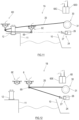
- a portion extending from the tip portion engaged with the locking tool 24 to the mooring bit 12 is referred to as a first portion 21, and a portion extending from the mooring bit 12 to the hawser drum 31 is referred to as a second portion 22.
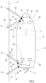
- FIG. 9 is a diagram showing one example of the direction in which the mooring rope 20 is wound around the mooring bit 12.
- the first portion 21 is located behind the second portion 22.
- the mooring rope 20 is hung to the mooring bit 12 from the front side to the rear side. Since the mooring rope 20 is hung to the mooring bit 12 as above, the mooring rope 20 hardly tangles when the floating structure 10 moves forward to separate from the mooring facility 11.
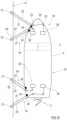
- FIG. 10 is a diagram showing one example of the direction in which the mooring rope 20 is wound around the mooring bit 12.
- the first portion 21 is located behind the second portion 22.
- the first portion 21 is located in front of the second portion 22.
- the mooring rope 20 located at the front portion of the floating structure 10 is hung to the mooring bit 12 from the front side to the rear side, and the mooring rope 20 located at the rear portion of the floating structure 10 is hung to the mooring bit 12 from the rear side to the front side.
- the tensile force applied to the first portion 21 and the tensile force applied to the second portion 22 are substantially equal to each other. However, in some cases, the tensile force applied to the first portion 21 is higher than the tensile force applied to the second portion 22. In such cases, an increase in the tensile force can be quickly detected by the tensile force sensor 26 located at the locking tool 24.
- FIG. 11 is a diagram showing that unmanned machines 6C and 6D hang the mooring rope 20 to the mooring bit 12 in the mooring system 1A according to Modified Example of Embodiment 2.
- the mooring system 1A according to Modified Example is different from the mooring system 1A according to Embodiment 2 in that the mooring system 1A according to Modified Example includes conveyance unmanned machines (a first unmanned machine 6C and a second unmanned machine 6D) and control devices (a first control device 60C that controls the first unmanned machine 6C and a second control device 60D that controls the second unmanned machine 6D) located at the respective unmanned machines.
- the same reference signs are used in the drawings for the components that are the same as or similar to those in Embodiment 2, and explanations thereof are omitted.
- the first unmanned machine 6C and the second unmanned machine 6D is substantially the same in configuration as the unmanned machine 6 of the mooring system 1 according to Embodiment 1.
- the first control device 60C is substantially the same in configuration as the control device 60 of the mooring system 1 according to Embodiment 1.
- the first unmanned machine 6C is manually or automatically controlled by the first control device 60C.
- the second control device 60D is substantially the same in configuration as the control device 60 of the mooring system 1 according to Embodiment 1.
- the second control device 60D may further include a function of controlling the second unmanned machine 6D such that the second unmanned machine 6D automatically follows the first unmanned machine 6C.
- the position of the second unmanned machine 6D relative to the first unmanned machine 6C when the second unmanned machine 6D follows the first unmanned machine 6C is set in advance. For example, when the second unmanned machine 6D flies, the second unmanned machine 6D is the same in height as the first unmanned machine 6C and is located behind the first unmanned machine 6C by several meters.
- the first control device 60C and/or the second control device 60D can switch a control method such that the first unmanned machine 6C and/or the second unmanned machine 6D is manually controlled.
- the unmooring method using the mooring system 1A according to Modified Example is substantially the same as that in Embodiment 1.
- the mooring method using the mooring system 1A according to Modified Example roughly includes (1) a preparing step, (2) a rope hanging step, and (3) a rope tensing step. Since (3) the rope tensing step using the mooring system 1A according to Modified Example is substantially the same as that in Embodiment 1, an explanation thereof is omitted.
- the mooring rope 20 is unwound from the hawser drum 31.
- the mooring rope 20 may be unwound in advance from the hawser drum 31 by a length adequate when the mooring rope 20 extends to the mooring bit 12 and returns, or may be unwound little by little from the hawser drum 31 in accordance with the movement of the unmanned machine 6C.
- the tip portion of the unwound mooring rope 20 (or the heaving line connected to the tip portion) is held by the holding tool 69 of the first unmanned machine 6C.
- the tip portion of the mooring rope 20 may include a loop, and the loop may be hung to the holding tool 69.
- the tip portion of the mooring rope 20 may be tied to the holding tool 69.
- the intermediate portion of the mooring rope 20 which is located between the tip portion locked to the locking tool 24 and the base portion unwound from the winch 30 is held by the holding tool 69 of the second unmanned machine 6D.
- the first unmanned machine 6C and the second unmanned machine 6D stand by at the stand-by positions defined at the floating structure 10.
- the first unmanned machine 6C and the second unmanned machine 6D may be manually controlled by the manipulator, or at least one of the first unmanned machine 6C and the second unmanned machine 6D may be automatically controlled to perform autonomous flight.
- the first unmanned machine 6C departs from the stand-by position, moves to the mooring bit 12, hangs the mooring rope 20 to the mooring bit 12, and returns to the stand-by position again.
- the mooring rope 20 is hung to the mooring bit 12 in such a manner that the holding tool 69 of the first unmanned machine 6C turns about the mooring bit 12 so as to draw an arc.
- the second unmanned machine 6D departs from the stand-by position and moves to the mooring bit 12.
- the second unmanned machine 6D may perform autonomous flight from the stand-by position to the mooring bit 12 so as to follow the first unmanned machine 6C.
- the second unmanned machine 6D hovers at a position beyond the mooring bit 12.
- the second unmanned machine 6D pulls the mooring rope 20 at a side where the mooring facility 11 is located such that the mooring bit 12 is located within the loop of the mooring rope 20.
- the operator receives the tip portion of the mooring rope 20 from the first unmanned machine 6C and engages the tip portion of the mooring rope 20 with the locking tool 24. After the tip portion of the mooring rope 20 is locked to the locking tool 24, the second unmanned machine 6D releases the mooring rope 20.
- the mooring system 1A is a mooring system that moors the floating structure 10 to the mooring facility 11, one of the floating structure 10 and the mooring facility 11 being the first object, the other being the second object, the mooring system 1A including:
- the mooring method according to Modified Example of the present embodiment is a mooring method of mooring the floating structure 10 to the mooring facility 11, one of the floating structure 10 and the mooring facility 11 being the first object, the other being the second object, the mooring method including:
- the rope hanging work is performed by the cooperation of the first unmanned machine 6C and the second unmanned machine 6D.
- the tension of the mooring rope 20 is maintained by the second unmanned machine 6D from when the first unmanned machine 6C hangs the mooring rope 20 to the mooring bit 12 until the first unmanned machine 6C returns to the second object. Therefore, the mooring rope 20 can be prevented from loosening and coming off from the mooring bit 12.
- FIG. 12 is a diagram showing the configuration of the mooring system 1B according to Embodiment 3 of the present disclosure.
- the mooring system 1B according to Embodiment 3 shown in FIG. 12 is different from the mooring system 1 according to Embodiment 1 in that the mooring system 1B further includes a leading unmanned machine 6E and a leading control device 60E configured to control the leading unmanned machine 6E. Except for these differences, the mooring system 1B according to Embodiment 3 is substantially the same in configuration as the mooring system 1 according to Embodiment 1. Therefore, in the present embodiment, differences from the mooring system 1 according to Embodiment 1 will be described in detail.
- the same reference signs are used in the drawings for the components that are the same as or similar to those in Embodiment 1, and explanations thereof are omitted.
- the leading control device 60E is substantially the same in configuration as the control device 60 of the mooring system 1 according to Embodiment 1.
- the leading unmanned machine 6E is manually or automatically controlled by the leading control device 60E.
- the control device 60 is substantially the same in configuration as the control device 60 of the mooring system 1 according to Embodiment 1, and in addition, includes a function of controlling the conveyance unmanned machine 6 such that the conveyance unmanned machine 6 automatically follows the leading unmanned machine 6E.
- the control device 60 can switch the control method such that the conveyance unmanned machine 6 is manually controlled.
- the position of the conveyance unmanned machine 6 relative to the leading unmanned machine 6E when the conveyance unmanned machine 6 follows the leading unmanned machine 6E is set in advance. For example, when the conveyance unmanned machine 6 flies, the conveyance unmanned machine 6 is the same in height as the leading unmanned machine 6E and is located behind the leading unmanned machine 6E by several meters.
- the conveyance unmanned machine 6 includes the holding tool 69 that holds the mooring rope 20, and the mooring rope 20 is held by the conveyance unmanned machine 6. Therefore, an airframe that is larger in size and conveyance capacity than the leading unmanned machine 6E is adopted as the conveyance unmanned machine 6. Moreover, since the leading unmanned machine 6E does not carry the mooring rope 20, an airframe that is lighter than the conveyance unmanned machine 6 is adopted as the leading unmanned machine 6E, and sensors that search for a better route are mounted on the leading unmanned machine 6E.
- the mooring system 1B is a mooring system that moors the floating structure 10 to the mooring facility 11, one of the floating structure 10 and the mooring facility 11 being the first object, the other being the second object, the mooring system 1B including:
- the control device 60 controls the conveyance unmanned machine 6 such that the conveyance unmanned machine 6 follows the leading unmanned machine 6E.
- the leading control device 60E controls the leading unmanned machine 6E such that the conveyance unmanned machine 6 following the leading unmanned machine 6E moves from the second object to the mooring bit 12 located at the first object while holding the mooring rope 20, and hangs the intermediate portion of the mooring rope 20 to the mooring bit 12, the intermediate portion being a portion between the tip portion locked to the locking tool 24 and the base portion unwound from the winch 30.
- the mooring method according to the present embodiment is a mooring method of mooring the floating structure 10 to the mooring facility 11, one of the floating structure 10 and the mooring facility 11 being the first object, the other being the second object, the mooring method including:
- the leading unmanned machine 6E that searches for the route and the conveyance unmanned machine 6 that conveys the mooring rope 20 has the respective functions. Therefore, the leading unmanned machine 6E and the conveyance unmanned machine 6 can have the functions suitable for their respective roles. Thus, the accuracy of the searching of the route by the leading unmanned machine 6E can be improved, and therefore, the flight stability of the leading unmanned machine 6E and the conveyance unmanned machine 6 can be improved.
- the present specification discloses some embodiments. Two or more of some embodiments may be suitably combined with each other.
- the features of the mooring system 1B are applicable to the mooring system 1A according to Embodiment 2.
- the unmanned machine 6 may be controlled such that the leading unmanned machine 6E leads the movement of the unmanned machine 6, and the unmanned machine 6 follows the leading unmanned machine 6E.
- the functionality of the calculator 45 and the controller 68 disclosed herein may be implemented using circuitry or processing circuitry which includes general purpose processors, special purpose processors, integrated circuits, ASICs ("Application Specific Integrated Circuits"), conventional circuitry and/or combinations thereof which are configured or programmed to perform the disclosed functionality.
- Processors are considered processing circuitry or circuitry as they include transistors and other circuitry therein.
- the circuitry, units, or means are hardware that carry out the recited functionality.
- the hardware may be any hardware disclosed herein or otherwise known which is programmed or configured to carry out the recited functionality.
- the hardware is a processor which may be considered a type of circuitry
- the circuitry, means, or units are a combination of hardware and software, the software being used to configure the hardware and/or processor.
Landscapes
- Engineering & Computer Science (AREA)
- Mechanical Engineering (AREA)
- Chemical & Material Sciences (AREA)
- Ocean & Marine Engineering (AREA)
- Combustion & Propulsion (AREA)
- Aviation & Aerospace Engineering (AREA)
- Remote Sensing (AREA)
- Structural Engineering (AREA)
- Civil Engineering (AREA)
- Architecture (AREA)
- Electric Cable Installation (AREA)
- Load-Engaging Elements For Cranes (AREA)
- Forklifts And Lifting Vehicles (AREA)
Applications Claiming Priority (2)
| Application Number | Priority Date | Filing Date | Title |
|---|---|---|---|
| JP2021082667A JP7660023B2 (ja) | 2021-05-14 | 2021-05-14 | 係留システム及び係留方法 |
| PCT/JP2022/017179 WO2022239580A1 (ja) | 2021-05-14 | 2022-04-06 | 係留システム及び係留方法 |
Publications (1)
| Publication Number | Publication Date |
|---|---|
| EP4353578A1 true EP4353578A1 (de) | 2024-04-17 |
Family
ID=84028239
Family Applications (1)
| Application Number | Title | Priority Date | Filing Date |
|---|---|---|---|
| EP22807284.9A Withdrawn EP4353578A1 (de) | 2021-05-14 | 2022-04-06 | Verankerungssystem und verankerungsverfahren |
Country Status (5)
| Country | Link |
|---|---|
| EP (1) | EP4353578A1 (de) |
| JP (1) | JP7660023B2 (de) |
| KR (1) | KR20240005046A (de) |
| CN (1) | CN116829447B (de) |
| WO (1) | WO2022239580A1 (de) |
Cited By (1)
| Publication number | Priority date | Publication date | Assignee | Title |
|---|---|---|---|---|
| WO2026054364A1 (ko) * | 2024-09-05 | 2026-03-12 | 이소망 | 무어링 로프 데미지 모니터링 시스템 |
Families Citing this family (4)
| Publication number | Priority date | Publication date | Assignee | Title |
|---|---|---|---|---|
| US12623762B2 (en) * | 2022-10-24 | 2026-05-12 | University Of Florida Research Foundation, Inc. | Bathy-drone: an autonomous unmanned drone-tethered sonar system |
| KR102909683B1 (ko) * | 2023-08-28 | 2026-01-09 | 한국기계연구원 | 비행체를 이용한 선박 계류용 계류삭 제어시스템 |
| WO2026055093A1 (en) * | 2024-09-06 | 2026-03-12 | Delmar Systems, Inc. | Mooring release system |
| CN119218366B (zh) * | 2024-10-22 | 2025-05-27 | 青岛海洋地质研究所 | 一种海上无人艇的无人机吊装回收设备 |
Family Cites Families (10)
| Publication number | Priority date | Publication date | Assignee | Title |
|---|---|---|---|---|
| JPS59156093U (ja) * | 1983-04-05 | 1984-10-19 | 三菱重工業株式会社 | 係船ロ−プ保護装置 |
| JPS60252091A (ja) * | 1984-05-29 | 1985-12-12 | Nippon Kokan Kk <Nkk> | ブイ係船方法 |
| JPH0439192U (de) * | 1990-07-31 | 1992-04-02 | ||
| US10723415B2 (en) * | 2016-08-03 | 2020-07-28 | Mangrove Deep LLC | Mooring system for drifting energy converters |
| NO343118B1 (en) | 2016-08-05 | 2018-11-05 | Rolls Royce Marine As | Unmanned vehicle for rope transfer |
| NL2019382B1 (en) | 2017-08-01 | 2019-02-19 | Rotortug Holding B V | Methods and systems for line transfer |
| US10042067B1 (en) | 2017-09-25 | 2018-08-07 | The United States Of America As Represented By The Secretary Of The Navy | Safety system for a towed source |
| CN110104508A (zh) * | 2019-06-24 | 2019-08-09 | 广西翼界科技有限公司 | 一种系留无人机的收线控制机构 |
| CN111650949A (zh) * | 2020-06-30 | 2020-09-11 | 深圳高度创新技术有限公司 | 系留无人机控制系统及方法 |
| CN112027106B (zh) * | 2020-08-31 | 2023-03-07 | 西南科技大学 | 一种自适应收放线的无人机系留平台及无人机定位方法 |
-
2021
- 2021-05-14 JP JP2021082667A patent/JP7660023B2/ja active Active
-
2022
- 2022-04-06 KR KR1020237042161A patent/KR20240005046A/ko not_active Withdrawn
- 2022-04-06 CN CN202280012352.1A patent/CN116829447B/zh active Active
- 2022-04-06 WO PCT/JP2022/017179 patent/WO2022239580A1/ja not_active Ceased
- 2022-04-06 EP EP22807284.9A patent/EP4353578A1/de not_active Withdrawn
Cited By (1)
| Publication number | Priority date | Publication date | Assignee | Title |
|---|---|---|---|---|
| WO2026054364A1 (ko) * | 2024-09-05 | 2026-03-12 | 이소망 | 무어링 로프 데미지 모니터링 시스템 |
Also Published As
| Publication number | Publication date |
|---|---|
| WO2022239580A1 (ja) | 2022-11-17 |
| JP7660023B2 (ja) | 2025-04-10 |
| CN116829447A (zh) | 2023-09-29 |
| KR20240005046A (ko) | 2024-01-11 |
| JP2022175897A (ja) | 2022-11-25 |
| CN116829447B (zh) | 2026-04-28 |
Similar Documents
| Publication | Publication Date | Title |
|---|---|---|
| CN116829447B (zh) | 系留系统及系留方法 | |
| US11845521B2 (en) | Marine structure comprising a launch and recovery system | |
| CN109153433B (zh) | 远程控制拖船、陆基控制中心、系统以及控制拖船的方法 | |
| EP3436338B1 (de) | Verfahren und system für den betrieb einer oder mehrerer schleppschiffe | |
| DK179634B1 (en) | A TUGBOAT WITH A CRANE FOR HANDLING A TOWING LINE | |
| WO2017167905A1 (en) | A boat or ship with a collision prevention system | |
| EP3494040B1 (de) | Unbemanntes fahrzeug für seiltransfer | |
| CN114096460A (zh) | 一种用于操作系泊缆绳的方法和装置 | |
| JP2016132406A (ja) | 水中航走体揚収システム | |
| WO2017167888A1 (en) | A tugboat | |
| DK179117B1 (en) | Tugboat with crane or robot arm | |
| RU213951U1 (ru) | Устройство развёртываемого оборудования для подъёма груза | |
| JP2019038543A (ja) | 水中航走体揚収システム | |
| GB2641385A (en) | Underwater vehicle launch and recovery cradle, system and method | |
| CN116280117A (zh) | 一种用于船舶救援的水面水下机器人系统及其使用方法 |
Legal Events
| Date | Code | Title | Description |
|---|---|---|---|
| STAA | Information on the status of an ep patent application or granted ep patent |
Free format text: STATUS: THE INTERNATIONAL PUBLICATION HAS BEEN MADE |
|
| PUAI | Public reference made under article 153(3) epc to a published international application that has entered the european phase |
Free format text: ORIGINAL CODE: 0009012 |
|
| STAA | Information on the status of an ep patent application or granted ep patent |
Free format text: STATUS: REQUEST FOR EXAMINATION WAS MADE |
|
| 17P | Request for examination filed |
Effective date: 20231214 |
|
| AK | Designated contracting states |
Kind code of ref document: A1 Designated state(s): AL AT BE BG CH CY CZ DE DK EE ES FI FR GB GR HR HU IE IS IT LI LT LU LV MC MK MT NL NO PL PT RO RS SE SI SK SM TR |
|
| DAV | Request for validation of the european patent (deleted) | ||
| DAX | Request for extension of the european patent (deleted) | ||
| STAA | Information on the status of an ep patent application or granted ep patent |
Free format text: STATUS: THE APPLICATION HAS BEEN WITHDRAWN |
|
| 18W | Application withdrawn |
Effective date: 20250213 |