EP4353532A1 - Shoulder adjusting mechanism for seat backrest - Google Patents
Shoulder adjusting mechanism for seat backrest Download PDFInfo
- Publication number
- EP4353532A1 EP4353532A1 EP22819494.0A EP22819494A EP4353532A1 EP 4353532 A1 EP4353532 A1 EP 4353532A1 EP 22819494 A EP22819494 A EP 22819494A EP 4353532 A1 EP4353532 A1 EP 4353532A1
- Authority
- EP
- European Patent Office
- Prior art keywords
- transmission structure
- backrest frame
- base
- adjustment mechanism
- lead screw
- Prior art date
- Legal status (The legal status is an assumption and is not a legal conclusion. Google has not performed a legal analysis and makes no representation as to the accuracy of the status listed.)
- Pending
Links
- 230000007246 mechanism Effects 0.000 title claims abstract description 57
- 230000005540 biological transmission Effects 0.000 claims abstract description 92
- 238000003780 insertion Methods 0.000 claims description 19
- 230000037431 insertion Effects 0.000 claims description 19
- 238000005096 rolling process Methods 0.000 claims description 6
- 230000009286 beneficial effect Effects 0.000 description 2
Images


Classifications
-
- B—PERFORMING OPERATIONS; TRANSPORTING
- B60—VEHICLES IN GENERAL
- B60N—SEATS SPECIALLY ADAPTED FOR VEHICLES; VEHICLE PASSENGER ACCOMMODATION NOT OTHERWISE PROVIDED FOR
- B60N2/00—Seats specially adapted for vehicles; Arrangement or mounting of seats in vehicles
- B60N2/02—Seats specially adapted for vehicles; Arrangement or mounting of seats in vehicles the seat or part thereof being movable, e.g. adjustable
- B60N2/22—Seats specially adapted for vehicles; Arrangement or mounting of seats in vehicles the seat or part thereof being movable, e.g. adjustable the back-rest being adjustable
- B60N2/2222—Seats specially adapted for vehicles; Arrangement or mounting of seats in vehicles the seat or part thereof being movable, e.g. adjustable the back-rest being adjustable the back-rest having two or more parts
-
- B—PERFORMING OPERATIONS; TRANSPORTING
- B60—VEHICLES IN GENERAL
- B60N—SEATS SPECIALLY ADAPTED FOR VEHICLES; VEHICLE PASSENGER ACCOMMODATION NOT OTHERWISE PROVIDED FOR
- B60N2/00—Seats specially adapted for vehicles; Arrangement or mounting of seats in vehicles
- B60N2/02—Seats specially adapted for vehicles; Arrangement or mounting of seats in vehicles the seat or part thereof being movable, e.g. adjustable
- B60N2/0224—Non-manual adjustments, e.g. with electrical operation
- B60N2/02246—Electric motors therefor
- B60N2/02253—Electric motors therefor characterised by the transmission between the electric motor and the seat or seat parts
Definitions
- the present disclosure relates to the field of automobile seats, in particular, to shoulder adjustment mechanisms for seat backrests.
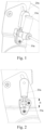
- FIG.1 a structural schematic view of a shoulder adjustment mechanism for a seat backrest in the prior art is shown.
- FIG 2 a front view of the shoulder adjustment mechanism for a seat backrest in the prior art is shown.
- a motor 10a is adopted to drive a main movement pair 20a to move up and down and meanwhile rotate about a bolt fixing point 30A, to thereby realize adjustment of the shoulder.
- the mounting point and rotating point of the shoulder adjustment mechanism in the prior art are at the same point 30a, and the movement stroke for shoulder adjustment depends on the length b of the lead screw, so the movement stroke is difficult to increase. If it is expected to increase the movement stroke for shoulder adjustment, the shoulder adjustment mechanism needs to be made larger, which may lead to large occupation space, high cost and poor applicability of the shoulder adjustment mechanism.
- An object of the present disclosure is to overcome the shortcomings in the prior art, by providing a shoulder adjustment mechanism for a seat backrest to solve the problem that the movement stroke of the shoulder adjustment mechanism is difficult to increase in the prior art.
- the present disclosure provides a shoulder adjustment mechanism for a seat backrest, comprising:
- a further improvement to the shoulder adjustment mechanism for a seat backrest according to the present disclosure lies in that:
- a further improvement to the shoulder adjustment mechanism for a seat backrest according to the present disclosure lies in that:
- a further improvement to the shoulder adjustment mechanism for a seat backrest according to the present disclosure lies in that: a first nut for limiting position is threadedly connected to a bottom end of the first lead screw.
- a further improvement to the shoulder adjustment mechanism for a seat backrest according to the present disclosure lies in that: the first transmission structure is a first worm-gear structure.
- a further improvement to the shoulder adjustment mechanism for a seat backrest according to the present disclosure lies in that, the shoulder adjustment mechanism further comprises:
- a further improvement to the shoulder adjustment mechanism for a seat backrest according to the present disclosure lies in that:
- a further improvement to the shoulder adjustment mechanism for a seat backrest according to the present disclosure lies in that:
- a further improvement to the shoulder adjustment mechanism for a seat backrest according to the present disclosure lies in that: a second nut for limiting position is threadedly connected to a bottom end of the second lead screw.
- a further improvement to the shoulder adjustment mechanism for a seat backrest according to the present disclosure lies in that: the second transmission structure is a second worm-gear structure.
- the shoulder adjustment mechanism for a seat backrest is beneficial in that:
- the seat backrest disclosed in the present disclosure comprises an upper backrest frame and a lower backrest frame in an up-and-down arrangement and hinged together, and a motor is used as a driving source to drive the first transmission structure to move the first lead screw up and down, and the lead screw brings the upper backrest frame into rotation relative to the lower backrest frame to thereby achieve adjustment of the shoulder.
- a spacing exists between the rotating position of the first transmission structure and the fixed position of the first base (that is, the rotating point of the first transmission structure is separate from the mounting and fixing point of the first base), and the first lead screw passes through the first transmission structure.
- the base and the first transmission structure may not be affected, and there is only a need to increase the length of the first lead screw without increasing the volume of the first transmission structure.
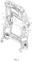
- FIGS. 3 and 4 are schematic views of the shoulder adjustment mechanism for a seat backrest according to the present disclosure before and after adjustment.
- FIGS. 5, 6 and 7 are enlarged views of Part A of FIG. 3 in three adjustment states.
- FIGS. 8 , 9 and 10 are side views of the opposite side of Part A of FIG. 3 in the three adjustment states.
- FIG. 11 is an exploded schematic view of the shoulder adjustment mechanism for a seat backrest according to the present disclosure.
- the shoulder adjustment mechanism for a seat backrest according to the present disclosure comprises:
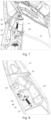
- FIG. 12 shows a structural schematic view of the shoulder adjustment mechanism for a seat backrest according to the present disclosure that is not mounted on the upper backrest frame and the lower backrest frame.
- FIG. 13 is an enlarged view of part B of FIG. 12 .
- FIG. 14 is a front view of FIG. 13 .
- FIG. 15 is an exploded schematic view of FIG.13 . As shown in FIGS.
- the first base 50 is provided with a first transverse hole in a transverse direction; the first base 50 is provided with a first rotating shaft 51 located on a rim of the first transverse hole; the first transmission structure 60 is placed within the first transverse hole, and an edge of the first transmission structure 60 is in rolling connection with the first rotating shaft 51; the first rotating shaft 51 is a rotating position where the first transmission structure 60 rotates relative to the first base 50.
- the first transverse hole is an arc-shaped hole.
- an edge of the first base 50 is fixed to the lower backrest frame 20 through a fixing bolt 52.
- the fixed position of the first base 50 is the position where the fixing bolt 52 is located.
- the first rotating shaft 51 and the fixing bolt 52 are not located at the same point, that is, the rotating position of the first transmission structure 60 is spaced from the fixed position of the first base 50, and they do not affect each other. If the adjustment stroke desires to be increased, it only needs to increase the length of the first lead screw 70 without affecting the first base 50 and the first transmission structure 60 and increasing the volume of the first transmission structure 60, so the shoulder adjustment mechanism can adapt to different stroke requirements and has saved space.
- the first base 50 is provided with a first vertical hole in a vertical direction and communicating with the first transverse hole;
- the first transmission structure 60 is provided with a first insertion hole in a vertical direction, and when the first transmission structure 60 is placed within the first transverse hole, the first insertion hole and the first vertical hole correspondingly communicate with each other;
- the first lead screw 70 penetrates through and placed within the first insertion hole and the first vertical hole.
- the first insertion hole is formed therein with a thread that is fit for the first lead screw 70.
- the first transmission structure 60 is provided therein with a nut, and the first lead screw 70 is inserted into the first transmission structure 60 and is in threaded connection with the nut within the first transmission structure 60.
- the motor drives the nut in the first transmission structure 60 to rotate through a worm-gear structure, which further brings the first lead screw 70 into up-and-down movement.
- the first lead screw 70 is provided with an external thread.
- a top portion of the first lead screw 70 is provided with a connecting hole for allowing the second hinge 40 to pass through.
- a thread is formed in the connecting hole at the top of the first lead screw 70.
- a first nut 71 for limiting position is threadedly connected to a bottom end of the first lead screw 70.
- the first nut 71 and a top portion of the first base 50 serve as two limiting end points for adjustment of the first lead screw 70.
- the first transmission structure 60 is a first worm-gear structure.
- the first worm-gear structure is driven to work to bring the first lead screw 70 into linear movement.
- both the first hinges 30 and the second hinges 40 are step bolts.
- two bushings 41 are further included.
- One bushing 41 is sandwiched between the upper backrest frame 10 and the lower backrest frame 20, and the other bushing 41 is sandwiched between the lower backrest frame 20 and the first lead screw 70.
- the second hinges 40 pass through the upper backrest frame 10 and the sliding grooves 200 in the lower backrest frame 20, the connecting hole in the first lead screw 70, and the two bushings 41 to achieve hinged connection of the upper backrest frame 10 with the lower backrest frame 20.
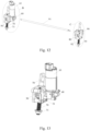
- FIG. 16 shows an enlarged view of part C of FIG. 12 .
- FIG. 17 is a front view of FIG.16 .
- FIG. 18 is an exploded schematic view of FIG. 16 . As shown in FIGS.
- the shoulder adjustment mechanism for a seat backrest further includes: a second base 80 fixed to the second side of the lower backrest frame 20; a second transmission structure 90 rotatably mounted on the second base 80, wherein a spacing exists between a rotating position of the second transmission structure 90 and a fixed position of the second base 80; a transverse shaft 91 transversely connected between the first transmission structure 60 and the second transmission structure 90; a second lead screw 92 in transmission connection with the second transmission structure 90 wherein a top portion of the second lead screw 92 is connected with another one of the second hinges 40.
- the transverse shaft 91 includes a flexible shaft and a sleeve fitted over the flexible shaft.
- the second base 80 is provided with a second transverse hole in a transverse direction; the second base 80 is provided with a second rotating shaft 81 located on a rim of the second transverse hole; the second transmission structure 90 is placed within the second transverse hole, and an edge of the second transmission structure 90 is in rolling connection with the second rotating shaft 81.
- the second base 80 is provided with a second vertical hole in a vertical direction and communicating with the second transverse hole;
- the second transmission structure 90 is provided with a second insertion hole in a vertical direction, and when the second transmission structure 90 is placed within the second transverse hole, the second insertion hole and the second vertical hole correspondingly communicate with each other;
- the second lead screw 92 penetrates through and placed within the second insertion hole and the second vertical hole.
- a second nut 93 for limiting position is threadedly connected to a bottom end of the second lead screw 92.
- the second transmission structure 90 is a second worm-gear structure.
- the second base 80, the second transmission structure 90 and the second lead screw 92 have the same structures as the first base 50, the first transmission structure 60 and the first lead screw 70.
- the linkage between two sides of the seat backrest can be realized by means of the transverse shaft 91 transversely connected between the first transmission structure 60 and the second transmission structure 90 to transmit a driving force.
- the shoulder adjustment mechanism for a seat backrest is beneficial in that:
- the seat backrest disclosed in the present disclosure comprises an upper backrest frame and a lower backrest frame in an up-and-down arrangement and hinged together, and a motor is used as a driving source to drive the first transmission structure to move the first lead screw up and down, and accordingly the lead screw brings the upper backrest frame into rotation relative to the lower backrest frame to thereby achieve adjustment of the shoulder.
- a spacing exists between the rotating position of the first transmission structure and the fixed position of the first base (that is, the rotating point of the first transmission structure is separate from the mounting and fixing point of the first base), and the first lead screw passes through the first transmission structure.
- the base and the first transmission structure may not be affected, and there is only a need to increase the length of the first lead screw without increasing the volume of the first transmission structure.
- the shoulder adjustment mechanism according to the present disclosure adaptable to different stroke requirements and have stronger applicability and saved space, and can achieve the function of shoulder adjustment.
- the length of the lead screw can also be adjusted to meet different requirements for different movement strokes of the shoulder adjustment mechanism.
Landscapes
- Engineering & Computer Science (AREA)
- Aviation & Aerospace Engineering (AREA)
- Transportation (AREA)
- Mechanical Engineering (AREA)
- Chairs For Special Purposes, Such As Reclining Chairs (AREA)
- Seats For Vehicles (AREA)
Abstract
The present disclosure relates to a shoulder adjustment mechanism for a seat backrest, comprising: an upper backrest frame (10) and a lower backrest frame (20) in an up-and-down arrangement, each of the upper backrest frame (10) and the lower backrest frame (20) including a first side and a second side opposing to each other in a left-right direction, a third side facing a seat, and a fourth side facing away from the seat; a pair of first hinges (30) hingedly connected to the first sides and the second sides of the upper backrest frame (10) and the lower backrest frame (20) and close to the third sides; a pair of second hinges (40) hingedly connected to the first sides and the second sides of the upper backrest frame (10) and the lower backrest frame (20) and close to the fourth sides, the lower backrest frame (20) being provided with sliding grooves (200); a first base (50) fixed to the lower backrest frame (20); a first transmission structure (60) rotatably mounted on the first base (50) and in driving connection with a motor, wherein a spacing exists between a rotating position of the first transmission structure (60) and a fixed position of the first base (50); a first lead screw (70) in transmission connection with the first transmission structure (60) and connected with the second hinge (40), wherein the motor drives the first lead screw (70) to move through the first transmission structure (60), thereby bringing the second hinges (40) to move in the sliding grooves (200).
Description
- The present disclosure relates to the field of automobile seats, in particular, to shoulder adjustment mechanisms for seat backrests.
- With the development of the automobile industry and the changes in the automobile market, in order to improve user experiences, more and higher demands are put forward for functions and comfortability of the automobile.
- Referring to
FIG.1 , a structural schematic view of a shoulder adjustment mechanism for a seat backrest in the prior art is shown. Referring toFIG 2 , a front view of the shoulder adjustment mechanism for a seat backrest in the prior art is shown. As shown inFIG.1 and FIG.2 , amotor 10a is adopted to drive amain movement pair 20a to move up and down and meanwhile rotate about a bolt fixing point 30A, to thereby realize adjustment of the shoulder. The mounting point and rotating point of the shoulder adjustment mechanism in the prior art are at thesame point 30a, and the movement stroke for shoulder adjustment depends on the length b of the lead screw, so the movement stroke is difficult to increase. If it is expected to increase the movement stroke for shoulder adjustment, the shoulder adjustment mechanism needs to be made larger, which may lead to large occupation space, high cost and poor applicability of the shoulder adjustment mechanism. - An object of the present disclosure is to overcome the shortcomings in the prior art, by providing a shoulder adjustment mechanism for a seat backrest to solve the problem that the movement stroke of the shoulder adjustment mechanism is difficult to increase in the prior art.
- The aforesaid object is achieved by the following technical solution:
The present disclosure provides a shoulder adjustment mechanism for a seat backrest, comprising: - an upper backrest frame and a lower backrest frame in an up-and-down arrangement, each of the upper backrest frame and the lower backrest frame including a first side and a second side opposing to each other in a left-right direction, a third side facing a seat, and a fourth side facing away from the seat;
- a pair of first hinges hingedly connected to the first sides and the second sides of the upper backrest frame and the lower backrest frame and close to the third sides;
- a pair of second hinges hingedly connected to the first sides and the second sides of the upper backrest frame and the lower backrest frame and close to the fourth sides, the lower backrest frame being provided with sliding grooves for allowing movement of the second hinges;
- a first base fixed to the first side of the lower backrest frame;
- a first transmission structure rotatably mounted on the first base and in driving connection with a motor, wherein a spacing exists between a rotating position of the first transmission structure and a fixed position of the first base;
- a first lead screw in transmission connection with the first transmission structure, wherein a top portion of the first lead screw is connected with one of the second hinges, and wherein the motor drives the first lead screw to move up and down through the first transmission structure, and accordingly the first lead screw brings the second hinges to move in the sliding grooves, thus realizing rotation of the upper backrest frame about the first hinges relative to the lower backrest frame.
- A further improvement to the shoulder adjustment mechanism for a seat backrest according to the present disclosure lies in that:
- the first base is provided with a first transverse hole in a transverse direction;
- the first base is provided with a first rotating shaft located on a rim of the first transverse hole;
- the first transmission structure is placed within the first transverse hole, and an edge of the first transmission structure is in rolling connection with the first rotating shaft.
- A further improvement to the shoulder adjustment mechanism for a seat backrest according to the present disclosure lies in that:
- the first base is provided with a first vertical hole in a vertical direction and communicating with the first transverse hole;
- the first transmission structure is provided with a first insertion hole in a vertical direction, and when the first transmission structure is placed within the first transverse hole, the first insertion hole and the first vertical hole correspondingly communicate with each other;
- the first lead screw penetrates through and placed within the first insertion hole and the first vertical hole.
- A further improvement to the shoulder adjustment mechanism for a seat backrest according to the present disclosure lies in that:
a first nut for limiting position is threadedly connected to a bottom end of the first lead screw. - A further improvement to the shoulder adjustment mechanism for a seat backrest according to the present disclosure lies in that:
the first transmission structure is a first worm-gear structure. - A further improvement to the shoulder adjustment mechanism for a seat backrest according to the present disclosure lies in that, the shoulder adjustment mechanism further comprises:
- a second base fixed to the second side of the lower backrest frame;
- a second transmission structure rotatably mounted on the second base, wherein a spacing exists between a rotating position of the second transmission structure and a fixed position of the second base;
- a transverse shaft transversely connected between the first transmission structure and the second transmission structure;
- a second lead screw in transmission connection with the second transmission structure, wherein a top portion of the second lead screw is connected with another one of the second hinges.
- A further improvement to the shoulder adjustment mechanism for a seat backrest according to the present disclosure lies in that:
- the second base is provided with a second transverse hole in a transverse direction;
- the second base is provided with a second rotating shaft located on a rim of the second transverse hole;
- the second transmission structure is placed within the second transverse hole, and an edge of the second transmission structure is in rolling connection with the second rotating shaft.
- A further improvement to the shoulder adjustment mechanism for a seat backrest according to the present disclosure lies in that:
- the second base is provided with a second vertical hole in a vertical direction and communicating with the second transverse hole;
- the second transmission structure is provided with a second insertion hole in a vertical direction, and when the second transmission structure is placed within the second transverse hole, the second insertion hole and the second vertical hole correspondingly communicate with each other;
- the second lead screw penetrates through and placed within the second insertion hole and the second vertical hole.
- A further improvement to the shoulder adjustment mechanism for a seat backrest according to the present disclosure lies in that:
a second nut for limiting position is threadedly connected to a bottom end of the second lead screw. - A further improvement to the shoulder adjustment mechanism for a seat backrest according to the present disclosure lies in that:
the second transmission structure is a second worm-gear structure. - The shoulder adjustment mechanism for a seat backrest according to the present disclosure is beneficial in that:
The seat backrest disclosed in the present disclosure comprises an upper backrest frame and a lower backrest frame in an up-and-down arrangement and hinged together, and a motor is used as a driving source to drive the first transmission structure to move the first lead screw up and down, and the lead screw brings the upper backrest frame into rotation relative to the lower backrest frame to thereby achieve adjustment of the shoulder. - In the present disclosure, a spacing exists between the rotating position of the first transmission structure and the fixed position of the first base (that is, the rotating point of the first transmission structure is separate from the mounting and fixing point of the first base), and the first lead screw passes through the first transmission structure. In this way, if the stroke needs to be increased, the base and the first transmission structure may not be affected, and there is only a need to increase the length of the first lead screw without increasing the volume of the first transmission structure. This makes the shoulder adjustment mechanism according to the present disclosure adaptable to different stroke requirements and have saved space and stronger applicability and can achieve the function of shoulder adjustment. In addition, the length of the lead screw can also be adjusted to meet different requirements for different movement strokes of the shoulder adjustment mechanism.
-
-
FIG.1 is a structural schematic view of a shoulder adjustment mechanism for a seat backrest in the prior art. -
FIG 2 is a front view of the shoulder adjustment mechanism for a seat backrest in the prior art. -
FIGS. 3 and4 are schematic views of the shoulder adjustment mechanism for a seat backrest according to the present disclosure before and after adjustment. -
FIGS. 5, 6 and7 are enlarged views of Part A ofFIG. 3 in three adjustment states. -
FIGS. 8 ,9 and 10 are side views of the opposite side of Part A ofFIG. 3 in the three adjustment states. -
FIG. 11 is an exploded schematic view of the shoulder adjustment mechanism for a seat backrest according to the present disclosure. -
FIG. 12 is a schematic structural view of the shoulder adjustment mechanism for a seat backrest according to the present disclosure, which is not mounted on an upper backrest frame and a lower backrest frame. -
FIG. 13 is an enlarged view of part B ofFIG. 12 . -
FIG. 14 is a front view ofFIG. 13 . -
FIG. 15 is an exploded schematic view ofFIG. 13 . -
FIG. 16 is an enlarged view of part C ofFIG. 12 . -
FIG. 17 is a front view ofFIG. 16 . -
FIG. 18 is an exploded schematic view ofFIG. 16 . - The present disclosure will be further described with reference to the attached drawings and specific embodiments.
- Refer to
FIGS. 3 and4 , which are schematic views of the shoulder adjustment mechanism for a seat backrest according to the present disclosure before and after adjustment.FIGS. 5, 6 and7 are enlarged views of Part A ofFIG. 3 in three adjustment states.FIGS. 8 ,9 and 10 are side views of the opposite side of Part A ofFIG. 3 in the three adjustment states.FIG. 11 is an exploded schematic view of the shoulder adjustment mechanism for a seat backrest according to the present disclosure. As shown inFIGS. 3 to 11 , the shoulder adjustment mechanism for a seat backrest according to the present disclosure comprises: - an
upper backrest frame 10 and alower backrest frame 20 in an up-and-down arrangement, each of the upper backrest frame and the lower backrest frame including a first side and a second side opposing to each other in a left-right direction, a third side facing a seat, and a fourth side facing away from the seat; - a pair of
first hinges 30 hingedly connected to the first sides and the second sides of theupper backrest frame 10 and thelower backrest frame 20 and close to the third sides; - a pair of
second hinges 40 hingedly connected to the first sides and the second sides of theupper backrest frame 10 and thelower backrest frame 20 and close to the fourth sides, thelower backrest frame 20 being provided with slidinggrooves 200 for allowing movement of the second hinges 40 (seeFIG. 11 ). - a
first base 50 fixed to the first side of thelower backrest frame 20; - a
first transmission structure 60 rotatably mounted on thefirst base 50 and in driving connection with amotor 61, wherein a spacing exists between a rotating position of thefirst transmission structure 60 and a fixed position of thefirst base 50; - a
first lead screw 70 in transmission connection with thefirst transmission structure 60, wherein a top portion of thefirst lead screw 70 is connected with one of the second hinges 40, wherein themotor 61 drives thefirst lead screw 70 to move up and down through thefirst transmission structure 60, and accordingly thefirst lead screw 70 brings the second hinges 40 to move in the sliding grooves, thus realizing rotation of theupper backrest frame 10 about the first hinges 30 relative to thelower backrest frame 20. - As a preferred embodiment of the shoulder adjustment mechanism for a seat backrest according to the present disclosure, refer to
FIG. 12 , which shows a structural schematic view of the shoulder adjustment mechanism for a seat backrest according to the present disclosure that is not mounted on the upper backrest frame and the lower backrest frame.FIG. 13 is an enlarged view of part B ofFIG. 12 .FIG. 14 is a front view ofFIG. 13 .FIG. 15 is an exploded schematic view ofFIG.13 . As shown inFIGS. 12 to 15 , thefirst base 50 is provided with a first transverse hole in a transverse direction; thefirst base 50 is provided with a firstrotating shaft 51 located on a rim of the first transverse hole; thefirst transmission structure 60 is placed within the first transverse hole, and an edge of thefirst transmission structure 60 is in rolling connection with the firstrotating shaft 51; the firstrotating shaft 51 is a rotating position where thefirst transmission structure 60 rotates relative to thefirst base 50. In this embodiment, the first transverse hole is an arc-shaped hole. - In this embodiment, an edge of the
first base 50 is fixed to thelower backrest frame 20 through a fixingbolt 52. The fixed position of thefirst base 50 is the position where the fixingbolt 52 is located. The firstrotating shaft 51 and the fixingbolt 52 are not located at the same point, that is, the rotating position of thefirst transmission structure 60 is spaced from the fixed position of thefirst base 50, and they do not affect each other. If the adjustment stroke desires to be increased, it only needs to increase the length of thefirst lead screw 70 without affecting thefirst base 50 and thefirst transmission structure 60 and increasing the volume of thefirst transmission structure 60, so the shoulder adjustment mechanism can adapt to different stroke requirements and has saved space. - As a preferred embodiment of the shoulder adjustment mechanism for a seat backrest according to the present disclosure, the
first base 50 is provided with a first vertical hole in a vertical direction and communicating with the first transverse hole; thefirst transmission structure 60 is provided with a first insertion hole in a vertical direction, and when thefirst transmission structure 60 is placed within the first transverse hole, the first insertion hole and the first vertical hole correspondingly communicate with each other; thefirst lead screw 70 penetrates through and placed within the first insertion hole and the first vertical hole. The first insertion hole is formed therein with a thread that is fit for thefirst lead screw 70. In this embodiment, thefirst transmission structure 60 is provided therein with a nut, and thefirst lead screw 70 is inserted into thefirst transmission structure 60 and is in threaded connection with the nut within thefirst transmission structure 60. In use, the motor drives the nut in thefirst transmission structure 60 to rotate through a worm-gear structure, which further brings thefirst lead screw 70 into up-and-down movement. - In this embodiment, the
first lead screw 70 is provided with an external thread. A top portion of thefirst lead screw 70 is provided with a connecting hole for allowing thesecond hinge 40 to pass through. In this embodiment, a thread is formed in the connecting hole at the top of thefirst lead screw 70. - As a preferred embodiment of the shoulder adjustment mechanism for a seat backrest according to the present disclosure, a
first nut 71 for limiting position is threadedly connected to a bottom end of thefirst lead screw 70. Thefirst nut 71 and a top portion of thefirst base 50 serve as two limiting end points for adjustment of thefirst lead screw 70. - In this embodiment, the
first transmission structure 60 is a first worm-gear structure. When an output shaft of the motor rotates, the first worm-gear structure is driven to work to bring thefirst lead screw 70 into linear movement. - In this embodiment, both the first hinges 30 and the second hinges 40 are step bolts.
- Further, as shown in
FIG. 11 , twobushings 41 are further included. One bushing 41is sandwiched between theupper backrest frame 10 and thelower backrest frame 20, and theother bushing 41 is sandwiched between thelower backrest frame 20 and thefirst lead screw 70. The second hinges 40 pass through theupper backrest frame 10 and the slidinggrooves 200 in thelower backrest frame 20, the connecting hole in thefirst lead screw 70, and the twobushings 41 to achieve hinged connection of theupper backrest frame 10 with thelower backrest frame 20. - As a preferred embodiment of the shoulder adjustment mechanism for a seat backrest according to the present disclosure, refer to
FIG. 16 , which shows an enlarged view of part C ofFIG. 12 .FIG. 17 is a front view ofFIG.16 .FIG. 18 is an exploded schematic view ofFIG. 16 . As shown inFIGS. 12 to 18 , the shoulder adjustment mechanism for a seat backrest according to the present disclosure further includes: asecond base 80 fixed to the second side of thelower backrest frame 20; asecond transmission structure 90 rotatably mounted on thesecond base 80, wherein a spacing exists between a rotating position of thesecond transmission structure 90 and a fixed position of thesecond base 80; atransverse shaft 91 transversely connected between thefirst transmission structure 60 and thesecond transmission structure 90; asecond lead screw 92 in transmission connection with thesecond transmission structure 90 wherein a top portion of thesecond lead screw 92 is connected with another one of the second hinges 40. In this embodiment, thetransverse shaft 91 includes a flexible shaft and a sleeve fitted over the flexible shaft. - As a preferred embodiment of the shoulder adjustment mechanism for a seat backrest according to the present disclosure, the
second base 80 is provided with a second transverse hole in a transverse direction; thesecond base 80 is provided with a secondrotating shaft 81 located on a rim of the second transverse hole; thesecond transmission structure 90 is placed within the second transverse hole, and an edge of thesecond transmission structure 90 is in rolling connection with the secondrotating shaft 81. - As a preferred embodiment of the shoulder adjustment mechanism for a seat backrest according to the present disclosure, the
second base 80 is provided with a second vertical hole in a vertical direction and communicating with the second transverse hole; thesecond transmission structure 90 is provided with a second insertion hole in a vertical direction, and when thesecond transmission structure 90 is placed within the second transverse hole, the second insertion hole and the second vertical hole correspondingly communicate with each other; thesecond lead screw 92 penetrates through and placed within the second insertion hole and the second vertical hole. - As a preferred embodiment of the shoulder adjustment mechanism for a seat backrest according to the present disclosure, a
second nut 93 for limiting position is threadedly connected to a bottom end of thesecond lead screw 92. In this embodiment, thesecond transmission structure 90 is a second worm-gear structure. - The
second base 80, thesecond transmission structure 90 and thesecond lead screw 92 have the same structures as thefirst base 50, thefirst transmission structure 60 and thefirst lead screw 70. The linkage between two sides of the seat backrest can be realized by means of thetransverse shaft 91 transversely connected between thefirst transmission structure 60 and thesecond transmission structure 90 to transmit a driving force. - The shoulder adjustment mechanism for a seat backrest according to the present disclosure is beneficial in that:
The seat backrest disclosed in the present disclosure comprises an upper backrest frame and a lower backrest frame in an up-and-down arrangement and hinged together, and a motor is used as a driving source to drive the first transmission structure to move the first lead screw up and down, and accordingly the lead screw brings the upper backrest frame into rotation relative to the lower backrest frame to thereby achieve adjustment of the shoulder. - In the present disclosure, a spacing exists between the rotating position of the first transmission structure and the fixed position of the first base (that is, the rotating point of the first transmission structure is separate from the mounting and fixing point of the first base), and the first lead screw passes through the first transmission structure. In this way, if the stroke needs to be increased, the base and the first transmission structure may not be affected, and there is only a need to increase the length of the first lead screw without increasing the volume of the first transmission structure. This makes the shoulder adjustment mechanism according to the present disclosure adaptable to different stroke requirements and have stronger applicability and saved space, and can achieve the function of shoulder adjustment. In addition, the length of the lead screw can also be adjusted to meet different requirements for different movement strokes of the shoulder adjustment mechanism.
- The present disclosure has been described in detail with reference to the attached drawings and embodiments, and those skilled in the art can make various changes to the present disclosure according to the above description. Therefore, some details in the embodiments shall not be construed as limiting the present disclosure, and the scope of protection of the present disclosure will be defined by the appended claims.
Claims (10)
- A shoulder adjustment mechanism for a seat backrest, characterized in that the shoulder adjustment mechanism comprises:an upper backrest frame and a lower backrest frame in an up-and-down arrangement, each of the upper backrest frame and the lower backrest frame including a first side and a second side opposing to each other in a left-right direction, a third side facing a seat, and a fourth side facing away from the seat;a pair of first hinges hingedly connected to the first sides and the second sides of the upper backrest frame and the lower backrest frame and close to the third sides;a pair of second hinges hingedly connected to the first sides and the second sides of the upper backrest frame and the lower backrest frame and close to the fourth sides, the lower backrest frame being provided with sliding grooves for allowing movement of the second hinges;a first base fixed to the first side of the lower backrest frame;a first transmission structure rotatably mounted on the first base and in driving connection with a motor, wherein a spacing exists between a rotating position of the first transmission structure and a fixed position of the first base; anda first lead screw in transmission connection with the first transmission structure, wherein a top portion of the first lead screw is connected with the second hinge, and wherein the motor drives the first lead screw to move up and down through the first transmission structure, and accordingly the first lead screw brings the second hinges to move in the sliding grooves, thus realizing rotation of the upper backrest frame about the first hinges relative to the lower backrest frame.
- The shoulder adjustment mechanism for a seat backrest according to claim 1, characterized in that,the first base is provided with a first transverse hole in a transverse direction;the first base is provided with a first rotating shaft located on a rim of the first transverse hole;the first transmission structure is placed within the first transverse hole, and an edge of the first transmission structure is in rolling connection with the first rotating shaft.
- The shoulder adjustment mechanism for a seat backrest according to claim 2, characterized in that,the first base is provided with a first vertical hole in a vertical direction and communicating with the first transverse hole;the first transmission structure is provided with a first insertion hole in a vertical direction, and when the first transmission structure is placed within the first transverse hole, the first insertion hole and the first vertical hole correspondingly communicate with each other;the first lead screw penetrates through and placed within the first insertion hole and the first vertical hole.
- The shoulder adjustment mechanism for a seat backrest according to claim 1, characterized in that,
a first nut for limiting position is threadedly connected to a bottom end of the first lead screw. - The shoulder adjustment mechanism for a seat backrest according to claim 1, characterized in that,
the first transmission structure is a first worm-gear structure. - The shoulder adjustment mechanism for a seat backrest according to claim 1, characterized in that the shoulder adjustment mechanism further comprises:a second base fixed to the second side of the lower backrest frame;a second transmission structure rotatably mounted on the second base, wherein a spacing exists between a rotating position of the second transmission structure and a fixed position of the second base;a transverse shaft transversely connected between the first transmission structure and the second transmission structure; anda second lead screw in transmission connection with the second transmission structure, wherein a top portion of the second lead screw is connected with another one of the second hinges.
- The shoulder adjustment mechanism for a seat backrest according to claim 6, characterized in that,the second base is provided with a second transverse hole in a transverse direction;the second base is provided with a second rotating shaft located on a rim of the second transverse hole;the second transmission structure is placed within the second transverse hole, and an edge of the second transmission structure is in rolling connection with the second rotating shaft.
- The shoulder adjustment mechanism for a seat backrest according to claim 7, characterized in that,the second base is provided with a second vertical hole in a vertical direction and communicating with the second transverse hole;the second transmission structure is provided with a second insertion hole in a vertical direction, and when the second transmission structure is placed within the second transverse hole, the second insertion hole and the second vertical hole correspondingly communicate with each other;the second lead screw penetrates through and placed within the second insertion hole and the second vertical hole.
- The shoulder adjustment mechanism for a seat backrest according to claim 6, characterized in that,
a second nut for limiting position is threadedly connected to a bottom end of the second lead screw. - The shoulder adjustment mechanism for a seat backrest according to claim 6, characterized in that,
the second transmission structure is a second worm-gear structure.
Applications Claiming Priority (2)
| Application Number | Priority Date | Filing Date | Title |
|---|---|---|---|
| CN202121319747.5U CN215590552U (en) | 2021-06-11 | 2021-06-11 | Shoulder adjustment mechanism for a seat back |
| PCT/CN2022/097215 WO2022257896A1 (en) | 2021-06-11 | 2022-06-06 | Shoulder adjusting mechanism for seat backrest |
Publications (1)
| Publication Number | Publication Date |
|---|---|
| EP4353532A1 true EP4353532A1 (en) | 2024-04-17 |
Family
ID=79875108
Family Applications (1)
| Application Number | Title | Priority Date | Filing Date |
|---|---|---|---|
| EP22819494.0A Pending EP4353532A1 (en) | 2021-06-11 | 2022-06-06 | Shoulder adjusting mechanism for seat backrest |
Country Status (3)
| Country | Link |
|---|---|
| EP (1) | EP4353532A1 (en) |
| CN (1) | CN215590552U (en) |
| WO (1) | WO2022257896A1 (en) |
Families Citing this family (1)
| Publication number | Priority date | Publication date | Assignee | Title |
|---|---|---|---|---|
| CN215590552U (en) * | 2021-06-11 | 2022-01-21 | 延锋国际座椅系统有限公司 | Shoulder adjustment mechanism for a seat back |
Family Cites Families (7)
| Publication number | Priority date | Publication date | Assignee | Title |
|---|---|---|---|---|
| JP6871506B2 (en) * | 2017-02-08 | 2021-05-12 | テイ・エス テック株式会社 | Vehicle seats with center-folded seatbacks and center-folded seatbacks |
| CN207190864U (en) * | 2017-08-30 | 2018-04-06 | 重庆延锋安道拓汽车部件系统有限公司 | Headrest adjusting seat front and back |
| CN209257942U (en) * | 2018-11-28 | 2019-08-16 | 深圳市力辉电机有限公司 | A kind of lifting transmission mechanism |
| CN209365954U (en) * | 2018-12-29 | 2019-09-10 | 扬州恒新座椅有限公司 | Commercial seat shoulder regulating mechanism |
| CN111186345A (en) * | 2020-03-15 | 2020-05-22 | 麦格纳座椅(台州)有限公司 | Device for improving comfort level of automobile seat and increasing seating space |
| CN215590552U (en) * | 2021-06-11 | 2022-01-21 | 延锋国际座椅系统有限公司 | Shoulder adjustment mechanism for a seat back |
| CN114013350B (en) * | 2021-11-16 | 2023-02-28 | 恺博(常熟)座椅机械部件有限公司 | Seat adjusting mechanism |
-
2021
- 2021-06-11 CN CN202121319747.5U patent/CN215590552U/en active Active
-
2022
- 2022-06-06 EP EP22819494.0A patent/EP4353532A1/en active Pending
- 2022-06-06 WO PCT/CN2022/097215 patent/WO2022257896A1/en active Application Filing
Also Published As
| Publication number | Publication date |
|---|---|
| WO2022257896A1 (en) | 2022-12-15 |
| CN215590552U (en) | 2022-01-21 |
Similar Documents
| Publication | Publication Date | Title |
|---|---|---|
| EP4353532A1 (en) | Shoulder adjusting mechanism for seat backrest | |
| US5145233A (en) | Arrangement of headrest in seat | |
| US7510228B2 (en) | Seating apparatus for a vehicle | |
| CN1962310B (en) | Electric telescopic apparatus for vehicle seat | |
| US20160250957A1 (en) | 4-way lumbar support | |
| CN101744708B (en) | Three-dimensional massaging machine | |
| KR20010007390A (en) | Door glass lifting apparatus | |
| JP2020044858A (en) | Seat slide device | |
| US6543852B2 (en) | Headrest device | |
| KR101470213B1 (en) | Apparatus for seat side bolster of vehicle | |
| US5924668A (en) | Motorized vehicle seat lift mechanism | |
| CN115158117B (en) | Seat sliding device | |
| CN112901007A (en) | Automobile side door actuator | |
| CN114274848B (en) | Zero-gravity seat | |
| CN110901486A (en) | Seat headrest tilting mechanism and car seat | |
| CN212386367U (en) | Self-adaptive side waist support electric adjusting mechanism of automobile electric seat | |
| CN210390864U (en) | Height adjusting device of locomotive seat | |
| CN211641957U (en) | Electronic flank adjustment mechanism of anterior headrest | |
| CN112498203A (en) | Mechanical massage waist support | |
| CN218750596U (en) | Display installation mechanism and car | |
| KR102415251B1 (en) | Lumber support for vehicle seat with push type avtuating block | |
| CN112761442B (en) | Hidden hinge and door system | |
| CN217744949U (en) | Be used for dentistry backrest electric lift structure | |
| KR20200064313A (en) | Height adjustable powered seat | |
| CN216300862U (en) | Electric adjusting mechanism of seat backrest |
Legal Events
| Date | Code | Title | Description |
|---|---|---|---|
| STAA | Information on the status of an ep patent application or granted ep patent |
Free format text: STATUS: THE INTERNATIONAL PUBLICATION HAS BEEN MADE |
|
| PUAI | Public reference made under article 153(3) epc to a published international application that has entered the european phase |
Free format text: ORIGINAL CODE: 0009012 |
|
| STAA | Information on the status of an ep patent application or granted ep patent |
Free format text: STATUS: REQUEST FOR EXAMINATION WAS MADE |
|
| 17P | Request for examination filed |
Effective date: 20231117 |
|
| AK | Designated contracting states |
Kind code of ref document: A1 Designated state(s): AL AT BE BG CH CY CZ DE DK EE ES FI FR GB GR HR HU IE IS IT LI LT LU LV MC MK MT NL NO PL PT RO RS SE SI SK SM TR |