EP4353135A2 - Side brush and intelligent cleaning device - Google Patents
Side brush and intelligent cleaning device Download PDFInfo
- Publication number
- EP4353135A2 EP4353135A2 EP24161241.5A EP24161241A EP4353135A2 EP 4353135 A2 EP4353135 A2 EP 4353135A2 EP 24161241 A EP24161241 A EP 24161241A EP 4353135 A2 EP4353135 A2 EP 4353135A2
- Authority
- EP
- European Patent Office
- Prior art keywords
- side brush
- brush
- scraper
- base
- cleaning device
- Prior art date
- Legal status (The legal status is an assumption and is not a legal conclusion. Google has not performed a legal analysis and makes no representation as to the accuracy of the status listed.)
- Pending
Links
- 238000004140 cleaning Methods 0.000 title claims abstract description 78
- 230000002093 peripheral effect Effects 0.000 claims abstract description 3
- 238000007790 scraping Methods 0.000 claims description 57
- 239000003292 glue Substances 0.000 claims description 2
- 238000001746 injection moulding Methods 0.000 claims description 2
- 238000000034 method Methods 0.000 abstract 1
- 239000007788 liquid Substances 0.000 description 7
- 238000010586 diagram Methods 0.000 description 6
- 238000005108 dry cleaning Methods 0.000 description 5
- 239000004744 fabric Substances 0.000 description 5
- 238000005096 rolling process Methods 0.000 description 5
- 230000006870 function Effects 0.000 description 4
- 230000003993 interaction Effects 0.000 description 4
- 239000002699 waste material Substances 0.000 description 4
- 230000000694 effects Effects 0.000 description 3
- 239000000463 material Substances 0.000 description 3
- 230000008447 perception Effects 0.000 description 3
- 239000000428 dust Substances 0.000 description 2
- 238000012986 modification Methods 0.000 description 2
- 230000004048 modification Effects 0.000 description 2
- 238000010408 sweeping Methods 0.000 description 2
- WHXSMMKQMYFTQS-UHFFFAOYSA-N Lithium Chemical compound [Li] WHXSMMKQMYFTQS-UHFFFAOYSA-N 0.000 description 1
- 229910005813 NiMH Inorganic materials 0.000 description 1
- 230000003139 buffering effect Effects 0.000 description 1
- 238000005516 engineering process Methods 0.000 description 1
- 230000014509 gene expression Effects 0.000 description 1
- 229910052744 lithium Inorganic materials 0.000 description 1
- 229920006395 saturated elastomer Polymers 0.000 description 1
- 238000012876 topography Methods 0.000 description 1
- 230000001052 transient effect Effects 0.000 description 1
Images


Classifications
-
- A—HUMAN NECESSITIES
- A46—BRUSHWARE
- A46B—BRUSHES
- A46B5/00—Brush bodies; Handles integral with brushware
- A46B5/002—Brush bodies; Handles integral with brushware having articulations, joints or flexible portions
- A46B5/0054—Brush bodies; Handles integral with brushware having articulations, joints or flexible portions designed to allow relative positioning of the head to body
- A46B5/0062—Brush bodies; Handles integral with brushware having articulations, joints or flexible portions designed to allow relative positioning of the head to body being flexible or resilient during use
- A46B5/0066—Flexible resilience by elastic deformation of the material
-
- A—HUMAN NECESSITIES
- A47—FURNITURE; DOMESTIC ARTICLES OR APPLIANCES; COFFEE MILLS; SPICE MILLS; SUCTION CLEANERS IN GENERAL
- A47L—DOMESTIC WASHING OR CLEANING; SUCTION CLEANERS IN GENERAL
- A47L11/00—Machines for cleaning floors, carpets, furniture, walls, or wall coverings
- A47L11/40—Parts or details of machines not provided for in groups A47L11/02 - A47L11/38, or not restricted to one of these groups, e.g. handles, arrangements of switches, skirts, buffers, levers
- A47L11/4036—Parts or details of the surface treating tools
-
- A—HUMAN NECESSITIES
- A46—BRUSHWARE
- A46B—BRUSHES
- A46B1/00—Brush bodies and bristles moulded as a unit
-
- A—HUMAN NECESSITIES
- A46—BRUSHWARE
- A46B—BRUSHES
- A46B13/00—Brushes with driven brush bodies or carriers
-
- A—HUMAN NECESSITIES
- A46—BRUSHWARE
- A46B—BRUSHES
- A46B13/00—Brushes with driven brush bodies or carriers
- A46B13/008—Disc-shaped brush bodies
-
- A—HUMAN NECESSITIES
- A46—BRUSHWARE
- A46B—BRUSHES
- A46B3/00—Brushes characterised by the way in which the bristles are fixed or joined in or on the brush body or carrier
- A46B3/005—Bristle carriers and bristles moulded as a unit
-
- A—HUMAN NECESSITIES
- A46—BRUSHWARE
- A46B—BRUSHES
- A46B5/00—Brush bodies; Handles integral with brushware
- A46B5/06—Brush bodies; Handles integral with brushware in the form of tapes, chains, flexible shafts, springs, mats or the like
-
- A—HUMAN NECESSITIES
- A47—FURNITURE; DOMESTIC ARTICLES OR APPLIANCES; COFFEE MILLS; SPICE MILLS; SUCTION CLEANERS IN GENERAL
- A47L—DOMESTIC WASHING OR CLEANING; SUCTION CLEANERS IN GENERAL
- A47L11/00—Machines for cleaning floors, carpets, furniture, walls, or wall coverings
- A47L11/24—Floor-sweeping machines, motor-driven
-
- A—HUMAN NECESSITIES
- A47—FURNITURE; DOMESTIC ARTICLES OR APPLIANCES; COFFEE MILLS; SPICE MILLS; SUCTION CLEANERS IN GENERAL
- A47L—DOMESTIC WASHING OR CLEANING; SUCTION CLEANERS IN GENERAL
- A47L11/00—Machines for cleaning floors, carpets, furniture, walls, or wall coverings
- A47L11/28—Floor-scrubbing machines, motor-driven
- A47L11/282—Floor-scrubbing machines, motor-driven having rotary tools
-
- A—HUMAN NECESSITIES
- A47—FURNITURE; DOMESTIC ARTICLES OR APPLIANCES; COFFEE MILLS; SPICE MILLS; SUCTION CLEANERS IN GENERAL
- A47L—DOMESTIC WASHING OR CLEANING; SUCTION CLEANERS IN GENERAL
- A47L9/00—Details or accessories of suction cleaners, e.g. mechanical means for controlling the suction or for effecting pulsating action; Storing devices specially adapted to suction cleaners or parts thereof; Carrying-vehicles specially adapted for suction cleaners
- A47L9/02—Nozzles
- A47L9/04—Nozzles with driven brushes or agitators
- A47L9/0461—Dust-loosening tools, e.g. agitators, brushes
- A47L9/0466—Rotating tools
-
- A—HUMAN NECESSITIES
- A46—BRUSHWARE
- A46B—BRUSHES
- A46B2200/00—Brushes characterized by their functions, uses or applications
- A46B2200/30—Brushes for cleaning or polishing
-
- A—HUMAN NECESSITIES
- A46—BRUSHWARE
- A46B—BRUSHES
- A46B3/00—Brushes characterised by the way in which the bristles are fixed or joined in or on the brush body or carrier
- A46B3/08—Brushes characterised by the way in which the bristles are fixed or joined in or on the brush body or carrier by clamping
- A46B3/10—Brushes characterised by the way in which the bristles are fixed or joined in or on the brush body or carrier by clamping into rings or the like
- A46B3/14—Brushes characterised by the way in which the bristles are fixed or joined in or on the brush body or carrier by clamping into rings or the like specially adapted for street-cleaning or rail-cleaning brooms
-
- A—HUMAN NECESSITIES
- A47—FURNITURE; DOMESTIC ARTICLES OR APPLIANCES; COFFEE MILLS; SPICE MILLS; SUCTION CLEANERS IN GENERAL
- A47L—DOMESTIC WASHING OR CLEANING; SUCTION CLEANERS IN GENERAL
- A47L2201/00—Robotic cleaning machines, i.e. with automatic control of the travelling movement or the cleaning operation
Definitions
- the present application relates to the field of cleaning tool technologies, and more specifically, to a side brush and an intelligent cleaning device.
- Existing intelligent cleaning devices such as intelligent cleaning machines are usually provided with side brushes at their bottoms.
- the side brushes are able to rotate to move debris on a floor surface to the cleaning region under the intelligent cleaning device.
- the embodiments of the present application provide a side brush that prevents itself from being entangled, and an intelligent cleaning device.
- this application provides a side brush, including a side brush base for mounting to an intelligent cleaning device, and a scraper connected to a peripheral side of the side brush base, where the scraper is configured to be in contact with the floor, so as to scrape sundries.
- the embodiments of the present application provide an intelligent cleaning device, including a device body and the foregoing side brush.
- the side brush in this application includes a scraper, so as to effectively prevent the side brush from being entangled by sundries such as hair, thereby improving the cleaning effect of the intelligent cleaning device and ensuring normal operation of the cleaning program of the intelligent cleaning device.
- first and second cited in the present application are merely identifiers and do not have any other meaning, such as a particular order.
- first component does not imply existence of “second component”
- second component does not imply existence of “first component”.
- an intelligent cleaning device mainly includes a device body.
- the device body can be in an approximate circular shape (both the front and the back are circular) or can be in other shapes. It can be understood that the intelligent cleaning device shown in the present application may be a sweeping robot, a mopping robot, a sweeping and mopping robot, or the like.
- the intelligent cleaning device includes a cleaning system, a perception system, a control system, a driving system, an energy system, a man-machine interaction system, and the like. Various systems cooperate with each other to make the intelligent cleaning device autonomously move and implement a cleaning task. Functional elements and the like that constitute the above-mentioned systems in the intelligent cleaning device are integrated into the device body.
- the device body includes an upper cover, a chassis, and a middle frame disposed between the upper cover and the chassis.
- the middle frame serves as a basic frame for disposing various functional elements.
- the upper cover and the chassis cover a surface of the device body to protect internal parts and improve appearance of the intelligent cleaning device.
- the driving system mainly includes a traveling wheel, a driving motor, and a control circuit for controlling the driving motor.
- the intelligent cleaning device may include one or more driven wheels, and the driven wheel include but are not limited to a caster.
- the perception system is used by the intelligent cleaning device to perceive an external environment such as topography.
- the perception system includes sensing apparatuses such as a position determining apparatus, a bumper, a cliff sensor, an ultrasonic sensor, an infrared sensor, a magnetometer, an accelerometer, a gyroscope, and an odometer. These sensing apparatuses provide various position information and motion state information of the intelligent cleaning device for the control system.
- the position determining apparatus includes but is not limited to an infrared emitter and receiver, a camera, and a laser ranging apparatus (laser distance sensor, LDS).
- the bumper is configured to relieve a collision between the intelligent cleaning devices and an object during movement.
- a layer of flexible material is provided on a surface of the bumper, and the bumper is mounted to the device body, and the predetermined distance between the bumper and the device body can ensure the sufficient time for the device body to decelerate in the case of a collision.
- the control system is provided on the main circuit board in the device body, and includes a non-transient memory, a computing processor, and the like.
- the computing processor may be a central processing unit, an application processor, or the like.
- the computing processor generates, based on obstacle information provided by the laser ranging apparatus and a positioning algorithm, an instant map of an environment in which the intelligent cleaning device is located.
- the control system may determine a current working status of the intelligent cleaning device, such as crossing a threshold, crossing an edge of a carpet, reaching a cliff, being stuck, full dust box, or being picked up.
- the control system provides next actions based on different situations, to make the performance of the intelligent cleaning device meet a certain requirement and improve user experience.
- the man-machine interaction system includes buttons on a panel of the robot, which are used for a user to select functions.
- the man-machine interaction system may further include a display screen, an indicator, and/or a speaker, which provide the current status of the machine or function options for the user.
- the man-machine interaction system may further include a mobile phone application. For a route-navigated intelligent cleaning device, the mobile phone application can show a map of the environment in which the device is located, as well as the location of the intelligent cleaning device, to the user, thereby providing the user with abundant and user-friendly function options.
- the energy system is configured to supply power to the elements of various systems, and mainly includes a rechargeable battery and a power supply circuit.
- the rechargeable battery can be a NiMH battery or a lithium battery.
- the rechargeable battery may be charged by contacting a charging device and a charging electrode disposed on a side or a bottom of the device body.
- the cleaning system is a important system of the intelligent cleaning device, and is configured to implement a cleaning function.
- the cleaning system includes a dry cleaning assembly and a wet cleaning assembly.
- the dry cleaning assembly mainly removes loose particulates from a to-be-cleaned surface by using a cleaning brush and the like.
- the wet cleaning assembly mainly mops the to-be-cleaned surface (such as a floor surface) by using a cleaning cloth saturated with cleaning liquid.
- the dry cleaning unit may mainly include a rolling brush, a waste container, and a vacuum.
- the vacuum is connected to the waste container through an air duct, and configured to generate suction force.
- the rolling brush interferes with the floor surface, the debris on the floor surface is agitated and taken to a suction door between the rolling brush and the waste container, and then sucked into the waste container by the suction force generated by the vacuum.
- the wet cleaning assembly may mainly include a liquid reservoir and a cleaning cloth.
- the liquid reservoir may be configured to contain cleaning liquid, and the cleaning cloth is detachably disposed on the liquid reservoir. After the dry cleaning unit completes cleaning, the liquid in the liquid reservoir flows to the cleaning cloth, and the cleaning cloth mops the floor surface cleaned by the rolling brush and the like.
- the dry cleaning unit may further include a side brush.
- the side brush is disposed on the device body with a rotation shaft. Specifically, the side brush may be mounted at the edge of the bottom of the device body. The side brush may rotate about the rotation shaft, so as to move the debris into a cleaning region of the rolling brush.
- the embodiments of the present application provide a side brush.
- the side brush is provided with a scraper 123, which is configured to rotate to remove debris.
- the movement of the scraper 123 mainly includes two types: traveling movement, which enables the intelligent cleaning device and the scraper 123 to reach a specified location; and rotation about a rotation shaft.
- a side brush 100 includes a side brush base 110 and a brush body 120.
- the side brush base 110 is mounted to the device body of the intelligent cleaning device.
- the brush body 120 extends outward from the side brush base 110 in a radial direction D1.
- At least one brush body 120 may be provided.
- there are at least two brush bodies 120, the brush bodies 120 may extend in a radial direction, and may be approximately evenly distributed around the side brush base 10.
- direction terms such as “downward”, “facing upward”, and “upward” that are used to describe the side brush 100 in this specification are relative to a horizontal mounting status of the side brush 100.
- radial direction D1 is a radial direction D1 relative to a rotation shaft of the side brush 100
- circumferential direction D2 is a circumferential direction D2 relative to the rotation shaft of the side brush 100
- axial direction D3 is a direction extending along the rotation shaft.
- “Outward from the side brush base 110” refers to a direction that is away from the side brush base 110.
- downward refers to a direction in which the axial direction D3 extends toward a free end of the brush body 120; and “upward” refers to a direction in which the axial direction D3 extends toward the side brush base 110.
- the brush body 120 includes a brush body mounting part 121 and a brush body extension part 122.
- the brush body mounting part 121 is configured to connect to the side brush base 110.
- the brush body extension part 122 extends outward in the radial direction D1 from the brush body mounting part 121 to cleaning debris.
- the brush body mounting part 121 and the brush body extension part 122 may be integrally formed. 0r the brush body extension part 122 may be assembled into the brush body mounting part 121 by buckling or clamping.
- the side brush 100 may be effectively prevented from being entangled by debris such as hair during cleaning, thereby improving the cleaning effect and ensuring operation of the cleaning.
- the brush body 120 may be formed through glue material injection molding, so that the brush body extension part 122 may have a property of flexibility, which plays a role of buffering. Therefore, during the cleaning, the brush body extension part 122 can efficiently clean debris, thereby implementing high dust pick up efficiency (DPU) of the intelligent cleaning device.
- DPU high dust pick up efficiency
- the brush body extension part 122 is connected to the brush body mounting part 121, and the present application is not limited thereto.
- the brush body extension part 122 may be directly connected to a brush body base 130, and in this case, and the brush body mounting part 121 may be omitted.
- the side brush 100 further includes the brush body base 130 that couples to the side brush base 110.
- the brush body mounting part 121 may be connected to the side brush base 110 through the brush body base 130.
- the brush body base 130 and the brush body 120 may be integrally formed.
- the brush body 120 may be connected to the brush body base 130, or the radial brush body and the brush body base 130 may be formed as an integral part.
- the integral part and the side brush base 110 may be separate members.
- the brush body base 130 and the side brush base 110 may be integrally formed.
- the side brush 100 and the side brush base 110 may be integrally formed, or the side brush 100 can be assembled into the side brush base 110.
- the brush body base 130 may be made of a plastic material. Therefore, the side brush 100 can closely couple to the rotation shaft for mounting.
- the brush body 120 may have at least one scraper 123.
- the scraper 123 includes a connecting part 1202 connected to the brush body mounting part 121, and a scraping part 1203 extending from the connecting part 1202 to the floor surface.
- the scraping part 1203 is in contact with the floor surface to scrape debris, which increases the surface of the scrapper 123 that contacts with debris, so that improve the cleaning performance.
- the scraper 123 moves the debris to the cleaning region under the intelligent cleaning device.
- there are at least two scrapers 123 the scrapers 123 clean the debris along the rotational direction of the side brush 100 sequentially. The front scraper 123 first clean the debris, and the debris that are not removed are further cleaned by the rear scraper 123, thereby improving the cleaning efficiency and cleaning effect.
- the scraper 123 includes a scraping part 1203 extending from the connecting part 1202 to the floor surface. During performing a cleaning task, the scraping part 1203 contacts with the floor surface to remove debris.
- the connecting part 1202 can serve as a scraping part, and the connecting part 1202 is in contact with the floor to remove debris. The scraping part extending to the floor surface may be omitted, which makes the structure simpler.
- the scraper 123 and the brush body extension part 122 are integrally formed, so that the brush body 120 may be formed as an integrally formed member.
- the scraper 123 may be coupled to the brush body mounting part 121 by buckling or clamping.
- the brush body extension part 122 may be provided with an opening 124 that extends in a radial direction D1 and penetrates the free end of the brush body 120. That is, the free end the brush body extension part 122 is separated by the opening 124.
- the opening 124 may be disposed between at least two adjacent scrapers 123.
- the opening 124 extends in the radial direction D1 from the middle of the brush body extension part 122 and penetrates the free end of the brush body 120.
- the scrapers 123 do not interfere with each other during cleaning, and elasticity of the scrapers 123 increases.
- a size of the opening 124 in the radial direction D1 can be greater than or equal to a size of the scraper 123 in the radial direction D1.
- the opening 124 completely separates the connecting parts 1202 of adjacent scrapers 123, and the present application is not limited thereto.
- the opening 124 can partially separate the connecting parts 1202 of adjacent scrapers 123.
- the brush body 120 is provided with the opening 124 to separate the connecting parts 1202 of the front scraper 123a and the rear scraper 123b. The present application is not limited thereto.
- the opening may be omitted, and the connecting parts 1202 of the front scraper 123a and the rear scraper 123b are connected to each other, that is, the scraper 123 includes the connecting part 1202, and the secondary scraping part 1204 and the scraping part 1203 that are formed through extension downward from two opposite sides of the connecting part 1202.
- the brush body 120 includes two scrapers 123, which are defined as the front scraper 123a and the rear scraper 123b in this specification.
- the front scraper 123a In the rotational direction of the side brush 100, the front scraper 123a is located in front of the rear scraper 123b in the rotational direction of the side brush 100.
- the front scraper 123a is first in contact with debris.
- the front scraper 123a first removes the sundries, and the sundries that are not removed by the front scraper 123a may be further removed by the rear scraper 123b, thereby improving the cleaning efficiency.
- the brush body extension part 122 is a plate-like part extending in the circumferential direction D2.
- the brush body extension part 122 gradually becomes narrower in the radial direction D1.
- the brush body extension part 122 is provided with the opening 124 between the front scraper 123a and the rear scraper 123b.
- the opening 124 separates a portion of the brush body extension part 122 near the free end into two smaller portions.
- the front scraper 123a and the rear scraper 123b are close to the edge of the brush body extension part 122 in the axial direction D1, so that there is a specific distance between the front scraper 123a and the rear scraper 123b.
- the connecting part 1202 can be coupled to the brush body extension part 122, or the connecting part 1202 and the brush body extension part 122 are integrally formed.
- the connecting part 1202 may be directly connected to the brush body base 130, in which case the brush body mounting part 121 is omitted.
- the rear scraper 123b includes a secondary scraping part 1204.
- the secondary scraping part 1204 In the rotational direction of the side brush 100, the secondary scraping part 1204 is located on a rear side of the scraping part 1203.
- the opening 124 separates the scraping part 1203 from the secondary scraping part 1204 completely or partially.
- overall widths of the secondary scraping parts 1204 are the same, and the present application is not limited thereto.
- the secondary scraping part 1204 gradually becomes smaller in a direction toward the floor, so as to prevent the secondary scraping part 1204 from being lifted away from the floor surface due to upwarping during sundries scraping.
- one scraper 123 may include a plurality of rear scrapers 123b; that is, one scraper may include a plurality of secondary scraping parts 1204.
- the secondary scraping part 1204 is disposed vertically relative to the floor.
- the scraping part 1203 includes a front end surface P1 and a rear end surface P3 that are disposed from front to back.
- the scraping part 1203 is inclined as a whole in the circumferential direction D2 relative to the rotational direction of the connecting part 1202 toward the side brush 100, so that the front end surface P1 of the scraping part 1203 away from the secondary scraping part 1204 may be formed as a bevel that is inclined outward in the circumferential direction D2 relative to the connecting part 1202, and a lower end (free end) of the front end surface P1 is further forward than an upper end of the front end surface P1. Therefore, during cleaning, the scraping part 1203 may scrape the debris more easily, especially the debris at an included angle of walls (the included angle between the floor and the wall), or the debris at an included angle between another object and the floor.
- the secondary scraping part 1204 may extend in the axial direction D3, so that the second surface P2 of the secondary scraping part 1204 facing the scraping part 1203 may be formed as an axial surface that extends in the axial direction D3. That is, when the side brush 100 is horizontally mounted, the second surface P2 of the secondary scraping part 1204 facing the scraping part 1203 is a plane that extends vertically.
- the scraping part 1203 further includes a tip 12031 that is located at the free end of the scraping part 1203 and that extends in the movement direction, so that the sundries can be scraped thoroughly.
- the scraping part 1203 is disposed as a whole in an inclined manner relative to the floor surface, so that in the rotational direction of the side brush 100, the front end surface P1 is disposed in an inclined manner relative to the floor, and the present application is not limited thereto.
- only the front end surface P1 is disposed in an inclined manner relative to the floor, and a lower end (free end) of the front end surface P1 is further forward than an upper end of the front end surface P1.
- the side brush may include a plurality of scrapers 123, and the scrapers 123 are configured to move in a rotational manner to scrape debris.
- the side brush includes five scrapers 123, and the five scrapers 123 are evenly distributed along a circumference of the side brush base 110.
- Each scraper 123 includes one scraping part 1203 and one secondary scraping part 1204.
- each scraper 123 may include a plurality of secondary scraping parts 1204.
- the present application is not limited thereto.
- all the scraping parts 1203 and secondary scraping parts 1204 may be in the same shape or different shapes, or some of them can be in different shapes.
- the quantity of the scrapers 123 is not limited in the present application, and may be set depending on actual needs.
- the scraping part 1203 may extend in the axial direction D3, and the front end surface P1 is an axial surface in the axial direction D3.
- the secondary scraping part 1204 may be slightly inclined toward the scraping part 1203, and the second surface P2 is a bevel that is slightly inclined toward the scraping part 1203, so that the secondary scraping part 1204 can scrape the debris more easily.
- the direction term "outward in a circumferential direction D2" used herein to describe the front scraper 123a refers to a direction of the front scraper 123a away from the rear scraper 123b in the circumferential direction D2.
- a thickness of the scraping part 1203 is greater than a thickness of the secondary scraping part 1204.
- the scraper in the present application is a plate-like part, and the thickness of the scraping part 1203 refers to a size in the circumferential direction D2. That is, the size L1 of the scraping part 1203 in the circumferential direction D2 is greater than the size L2 of the secondary scraping part 1204 in the circumferential direction D2.
- the side brush base 110 is a separate member.
- the side brush base 110 includes a side brush base body 111 and a boss 112 for mounting a rotation shaft.
- the side brush base body 111 is provided with a receiving part whose opening 114 faces upward.
- the boss 112 is located at the center of the side brush base body 111 and extends upward from the bottom of the receiving part.
- the brush body base 130 is accommodated in the receiving part, and is located between the boss 112 and the side brush base body 111 (refer to FIG. 1 ).
- the shape of the brush body base 130 adapts to the shape of the side brush base body 111.
- the side brush base body 111 is an approximate semisphere that has a receiving part
- the brush body base 130 is an approximate ring (refer to FIG. 3 )
- the boss 112 may be accommodated in a center hole 131 of the brush body base 130.
- the center of the boss 112 may be provided with a mounting hole 113 for mounting the rotation shaft.
- the mounting hole 113 is coaxial with the center hole 131 of the brush body base 130.
- the side brush base body 111 is provided with a side brush base opening 114 that corresponds to the brush body mounting part 121, and the brush body 120 penetrates the side brush base opening 114 and extends outward in the radial direction D1 (refer to FIG. 2 ).
- the shape of the brush body mounting part 121 adapts to the side brush base opening 114.
- a protrusion 115 for abutting against the brush body base 130 is disposed between adjacent side brush base openings 114, and the protrusion 115 extends upward from the side brush base body 111.
- An upper surface P3 of the protrusion 115 is formed as an arc-shaped surface.
- the brush body base 130 is provided with a recess 132 that corresponds to the protrusion 115.
- the recess 132 is recessed upward from a bottom surface P4 of the brush body base 130, and includes a side opening.
- the protrusion 115 can be confined to the recess 132.
- An upper surface P5 of the recess 132 is formed as an arc-shaped surface that corresponds to and abuts against the upper surface P3 of the protrusion 115.
Landscapes
- Engineering & Computer Science (AREA)
- Mechanical Engineering (AREA)
- Nozzles For Electric Vacuum Cleaners (AREA)
- Cleaning In General (AREA)
Abstract
A side brush (100) and an intelligent cleaning device. The side brush (100) comprises a side brush base (110) mounted on the intelligent cleaning device and a scraper (123) connected to a peripheral side of the side brush base (110), wherein the scraper (123) is used for contacting the ground to scrape sundries. 0n the basis of the structure of the side brush (100), the side brush (100) can be effectively prevented from being wound by the sundries in a cleaning process.
Description
- The present application relates to the field of cleaning tool technologies, and more specifically, to a side brush and an intelligent cleaning device.
- Existing intelligent cleaning devices such as intelligent cleaning machines are usually provided with side brushes at their bottoms. The side brushes are able to rotate to move debris on a floor surface to the cleaning region under the intelligent cleaning device.
- The embodiments of the present application provide a side brush that prevents itself from being entangled, and an intelligent cleaning device.
- According to an aspect, this application provides a side brush, including a side brush base for mounting to an intelligent cleaning device, and a scraper connected to a peripheral side of the side brush base, where the scraper is configured to be in contact with the floor, so as to scrape sundries.
- According to another aspect, the embodiments of the present application provide an intelligent cleaning device, including a device body and the foregoing side brush.
- The side brush in this application includes a scraper, so as to effectively prevent the side brush from being entangled by sundries such as hair, thereby improving the cleaning effect of the intelligent cleaning device and ensuring normal operation of the cleaning program of the intelligent cleaning device.
- The following accompanying drawings of the embodiments of the present application are used herein as a part of the present application for understanding of this application. The accompanying drawings show embodiments of the present application and descriptions of the embodiments, which are used to explain apparatuses and principles of the present application. In the drawings:
-
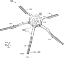
FIG. 1 is a schematic three-dimensional diagram of a side brush according to an optional embodiment of the present application; -
FIG. 2 is a schematic bottom view of a side brush shown inFIG. 1 ; -
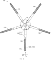
FIG. 3 is an exploded schematic three-dimensional diagram of the side brush shown inFIG. 1 ; -
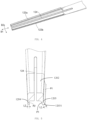
FIG. 4 is a partially enlarged diagram of a brush body shown inFIG. 1 ; -
FIG. 5 is a schematic cross-sectional diagram of a brush body shown inFIG. 1 ; -
FIG. 6 is a schematic three-dimensional diagram of a side brush base shown inFIG. 1 ; and -
FIG. 7 is a schematic three-dimensional diagram of a brush body and a brush body base shown inFIG. 1 . - The following describes specific details to provide a more thorough understanding of the present application. However, it is obvious to a person skilled in the art that the present application can be implemented without one or more of these details. In other examples, to avoid confusion with the present application, some technical features well known in the art are not described.
- To fully understand the present application, the following description provides a detailed structure to illustrate the present application. Clearly, the implementation of the present application is not limited to the specific details well known to a person skilled in the art. The following describes example embodiments of the present application in detail. However, in addition to these detailed descriptions, the present application can have other embodiments, and should not be construed as being limited to the embodiments provided herein.
- It should be understood that the terms used herein are merely intended to describe specific embodiments, and are not intended to limit the present application. The singular forms of "a/an", "one", and "the/said" are also intended to include plural forms, unless the context clearly indicates another manner. The terms "include" and/or "comprise" used in the specification specify existence of the features, entireties, steps, operations, elements and/or components, but do not exclude existence or addition of one or more of other features, entireties, steps, operations, elements, components, and/or a combination thereof. The terms "upper", "lower", "front", "rear", "left", "right" and similar expressions used in the present application are merely intended for illustrative purposes, and are not intended to impose a limitation.
- The ordinal numbers such as "first" and "second" cited in the present application are merely identifiers and do not have any other meaning, such as a particular order. In addition, for example, the term "first component" does not imply existence of "second component" and the term "second component" does not imply existence of "first component".
- The following describes in more detail the specific embodiments of the present application with reference to the accompanying drawings. These accompanying drawings illustrate representative embodiments of the present application and are not intended to limit the present application.
- Generally, an intelligent cleaning device mainly includes a device body. The device body can be in an approximate circular shape (both the front and the back are circular) or can be in other shapes. It can be understood that the intelligent cleaning device shown in the present application may be a sweeping robot, a mopping robot, a sweeping and mopping robot, or the like.
- The intelligent cleaning device includes a cleaning system, a perception system, a control system, a driving system, an energy system, a man-machine interaction system, and the like. Various systems cooperate with each other to make the intelligent cleaning device autonomously move and implement a cleaning task. Functional elements and the like that constitute the above-mentioned systems in the intelligent cleaning device are integrated into the device body. The device body includes an upper cover, a chassis, and a middle frame disposed between the upper cover and the chassis. The middle frame serves as a basic frame for disposing various functional elements. The upper cover and the chassis cover a surface of the device body to protect internal parts and improve appearance of the intelligent cleaning device.
- Autonomous movement of the intelligent cleaning system is implemented by the driving system. The driving system mainly includes a traveling wheel, a driving motor, and a control circuit for controlling the driving motor. To enable the intelligent cleaning device to move more stably on the floor or to have a stronger motion ability, the intelligent cleaning device may include one or more driven wheels, and the driven wheel include but are not limited to a caster.
- The perception system is used by the intelligent cleaning device to perceive an external environment such as topography. The perception system includes sensing apparatuses such as a position determining apparatus, a bumper, a cliff sensor, an ultrasonic sensor, an infrared sensor, a magnetometer, an accelerometer, a gyroscope, and an odometer. These sensing apparatuses provide various position information and motion state information of the intelligent cleaning device for the control system. The position determining apparatus includes but is not limited to an infrared emitter and receiver, a camera, and a laser ranging apparatus (laser distance sensor, LDS). The bumper is configured to relieve a collision between the intelligent cleaning devices and an object during movement. A layer of flexible material is provided on a surface of the bumper, and the bumper is mounted to the device body, and the predetermined distance between the bumper and the device body can ensure the sufficient time for the device body to decelerate in the case of a collision.
- The control system is provided on the main circuit board in the device body, and includes a non-transient memory, a computing processor, and the like. The computing processor may be a central processing unit, an application processor, or the like. The computing processor generates, based on obstacle information provided by the laser ranging apparatus and a positioning algorithm, an instant map of an environment in which the intelligent cleaning device is located. Base on the distance information and speed information provided by the bumper and the sensing apparatuses, the control system may determine a current working status of the intelligent cleaning device, such as crossing a threshold, crossing an edge of a carpet, reaching a cliff, being stuck, full dust box, or being picked up. In addition, the control system provides next actions based on different situations, to make the performance of the intelligent cleaning device meet a certain requirement and improve user experience.
- The man-machine interaction system includes buttons on a panel of the robot, which are used for a user to select functions. The man-machine interaction system may further include a display screen, an indicator, and/or a speaker, which provide the current status of the machine or function options for the user. The man-machine interaction system may further include a mobile phone application. For a route-navigated intelligent cleaning device, the mobile phone application can show a map of the environment in which the device is located, as well as the location of the intelligent cleaning device, to the user, thereby providing the user with abundant and user-friendly function options.
- The energy system is configured to supply power to the elements of various systems, and mainly includes a rechargeable battery and a power supply circuit. The rechargeable battery can be a NiMH battery or a lithium battery. When power of the rechargeable battery is less than a predetermined threshold, the rechargeable battery may be charged by contacting a charging device and a charging electrode disposed on a side or a bottom of the device body.
- The cleaning system is a important system of the intelligent cleaning device, and is configured to implement a cleaning function. The cleaning system includes a dry cleaning assembly and a wet cleaning assembly. The dry cleaning assembly mainly removes loose particulates from a to-be-cleaned surface by using a cleaning brush and the like. The wet cleaning assembly mainly mops the to-be-cleaned surface (such as a floor surface) by using a cleaning cloth saturated with cleaning liquid.
- The dry cleaning unit may mainly include a rolling brush, a waste container, and a vacuum. The vacuum is connected to the waste container through an air duct, and configured to generate suction force. Specifically, as the intelligent cleaning device moves, the rolling brush interferes with the floor surface, the debris on the floor surface is agitated and taken to a suction door between the rolling brush and the waste container, and then sucked into the waste container by the suction force generated by the vacuum.
- The wet cleaning assembly may mainly include a liquid reservoir and a cleaning cloth. The liquid reservoir may be configured to contain cleaning liquid, and the cleaning cloth is detachably disposed on the liquid reservoir. After the dry cleaning unit completes cleaning, the liquid in the liquid reservoir flows to the cleaning cloth, and the cleaning cloth mops the floor surface cleaned by the rolling brush and the like.
- The dry cleaning unit may further include a side brush. The side brush is disposed on the device body with a rotation shaft. Specifically, the side brush may be mounted at the edge of the bottom of the device body. The side brush may rotate about the rotation shaft, so as to move the debris into a cleaning region of the rolling brush.
- To resolve a problem that a bristle brush is easily entangled, the embodiments of the present application provide a side brush. The side brush is provided with a
scraper 123, which is configured to rotate to remove debris. The movement of thescraper 123 mainly includes two types: traveling movement, which enables the intelligent cleaning device and thescraper 123 to reach a specified location; and rotation about a rotation shaft. The following provides descriptions with reference to the accompanying drawings. - As shown in
FIG. 1 to FIG. 3 , aside brush 100 includes aside brush base 110 and abrush body 120. Theside brush base 110 is mounted to the device body of the intelligent cleaning device. Thebrush body 120 extends outward from theside brush base 110 in a radial direction D1. At least onebrush body 120 may be provided. In an embodiment, there are at least twobrush bodies 120, thebrush bodies 120 may extend in a radial direction, and may be approximately evenly distributed around the side brush base 10. - It should be noted that the direction terms such as "downward", "facing upward", and "upward" that are used to describe the
side brush 100 in this specification are relative to a horizontal mounting status of theside brush 100. It can be understood that "radial direction D1" is a radial direction D1 relative to a rotation shaft of theside brush 100; "circumferential direction D2" is a circumferential direction D2 relative to the rotation shaft of theside brush 100; and "axial direction D3" is a direction extending along the rotation shaft. "Outward from theside brush base 110" refers to a direction that is away from theside brush base 110. Further, for example, "downward" refers to a direction in which the axial direction D3 extends toward a free end of thebrush body 120; and "upward" refers to a direction in which the axial direction D3 extends toward theside brush base 110. - The
brush body 120 includes a brushbody mounting part 121 and a brushbody extension part 122. The brushbody mounting part 121 is configured to connect to theside brush base 110. The brushbody extension part 122 extends outward in the radial direction D1 from the brushbody mounting part 121 to cleaning debris. The brushbody mounting part 121 and the brushbody extension part 122 may be integrally formed. 0r the brushbody extension part 122 may be assembled into the brushbody mounting part 121 by buckling or clamping. In an embodiment, theside brush 100 may be effectively prevented from being entangled by debris such as hair during cleaning, thereby improving the cleaning effect and ensuring operation of the cleaning. Optionally, thebrush body 120 may be formed through glue material injection molding, so that the brushbody extension part 122 may have a property of flexibility, which plays a role of buffering. Therefore, during the cleaning, the brushbody extension part 122 can efficiently clean debris, thereby implementing high dust pick up efficiency (DPU) of the intelligent cleaning device. - In the illustrated embodiments, the brush
body extension part 122 is connected to the brushbody mounting part 121, and the present application is not limited thereto. In another embodiment, the brushbody extension part 122 may be directly connected to abrush body base 130, and in this case, and the brushbody mounting part 121 may be omitted. - The
side brush 100 further includes thebrush body base 130 that couples to theside brush base 110. The brushbody mounting part 121 may be connected to theside brush base 110 through thebrush body base 130. Referring toFIG. 3 , thebrush body base 130 and thebrush body 120 may be integrally formed. Specifically, thebrush body 120 may be connected to thebrush body base 130, or the radial brush body and thebrush body base 130 may be formed as an integral part. The integral part and theside brush base 110 may be separate members. In another embodiment, thebrush body base 130 and theside brush base 110 may be integrally formed. Theside brush 100 and theside brush base 110 may be integrally formed, or theside brush 100 can be assembled into theside brush base 110. Thebrush body base 130 may be made of a plastic material. Therefore, theside brush 100 can closely couple to the rotation shaft for mounting. - The
brush body 120 may have at least onescraper 123. As shown inFIG. 1 andFIG. 5 , thescraper 123 includes a connectingpart 1202 connected to the brushbody mounting part 121, and ascraping part 1203 extending from the connectingpart 1202 to the floor surface. Thescraping part 1203 is in contact with the floor surface to scrape debris, which increases the surface of thescrapper 123 that contacts with debris, so that improve the cleaning performance. During the cleaning, thescraper 123 moves the debris to the cleaning region under the intelligent cleaning device. In an embodiment, there are at least twoscrapers 123, thescrapers 123 clean the debris along the rotational direction of theside brush 100 sequentially. Thefront scraper 123 first clean the debris, and the debris that are not removed are further cleaned by therear scraper 123, thereby improving the cleaning efficiency and cleaning effect. - In the illustrated embodiments, the
scraper 123 includes ascraping part 1203 extending from the connectingpart 1202 to the floor surface. During performing a cleaning task, thescraping part 1203 contacts with the floor surface to remove debris. In another embodiment, the connectingpart 1202 can serve as a scraping part, and the connectingpart 1202 is in contact with the floor to remove debris. The scraping part extending to the floor surface may be omitted, which makes the structure simpler. - In an embodiment, the
scraper 123 and the brushbody extension part 122 are integrally formed, so that thebrush body 120 may be formed as an integrally formed member. In another embodiment, thescraper 123 may be coupled to the brushbody mounting part 121 by buckling or clamping. - Further, as shown in
FIG. 4 , in an embodiment, there are at least twoscrapers 123, the brushbody extension part 122 may be provided with anopening 124 that extends in a radial direction D1 and penetrates the free end of thebrush body 120. That is, the free end the brushbody extension part 122 is separated by theopening 124. Theopening 124 may be disposed between at least twoadjacent scrapers 123. Theopening 124 extends in the radial direction D1 from the middle of the brushbody extension part 122 and penetrates the free end of thebrush body 120. In an embodiment, thescrapers 123 do not interfere with each other during cleaning, and elasticity of thescrapers 123 increases. Optionally, a size of theopening 124 in the radial direction D1 can be greater than or equal to a size of thescraper 123 in the radial direction D1. - As shown in
FIG. 5 , theopening 124 completely separates the connectingparts 1202 ofadjacent scrapers 123, and the present application is not limited thereto. In another embodiment, theopening 124 can partially separate the connectingparts 1202 ofadjacent scrapers 123. In the illustrated embodiment, thebrush body 120 is provided with theopening 124 to separate the connectingparts 1202 of thefront scraper 123a and therear scraper 123b. The present application is not limited thereto. In another embodiment, the opening may be omitted, and the connectingparts 1202 of thefront scraper 123a and therear scraper 123b are connected to each other, that is, thescraper 123 includes the connectingpart 1202, and thesecondary scraping part 1204 and thescraping part 1203 that are formed through extension downward from two opposite sides of the connectingpart 1202. - In the illustrated embodiments, the
brush body 120 includes twoscrapers 123, which are defined as thefront scraper 123a and therear scraper 123b in this specification. In the rotational direction of theside brush 100, thefront scraper 123a is located in front of therear scraper 123b in the rotational direction of theside brush 100. During the operation of theside brush 100, thefront scraper 123a is first in contact with debris. Thefront scraper 123a first removes the sundries, and the sundries that are not removed by thefront scraper 123a may be further removed by therear scraper 123b, thereby improving the cleaning efficiency. Specifically, the brushbody extension part 122 is a plate-like part extending in the circumferential direction D2. In the illustrated embodiments, the brushbody extension part 122 gradually becomes narrower in the radial direction D1. The brushbody extension part 122 is provided with theopening 124 between thefront scraper 123a and therear scraper 123b. Theopening 124 separates a portion of the brushbody extension part 122 near the free end into two smaller portions. Thefront scraper 123a and therear scraper 123b are close to the edge of the brushbody extension part 122 in the axial direction D1, so that there is a specific distance between thefront scraper 123a and therear scraper 123b. - As shown in
FIG. 3 andFIG. 5 , the connectingpart 1202 can be coupled to the brushbody extension part 122, or the connectingpart 1202 and the brushbody extension part 122 are integrally formed. The connectingpart 1202 may be directly connected to thebrush body base 130, in which case the brushbody mounting part 121 is omitted. - The
rear scraper 123b includes asecondary scraping part 1204. In the rotational direction of theside brush 100, thesecondary scraping part 1204 is located on a rear side of thescraping part 1203. Theopening 124 separates thescraping part 1203 from thesecondary scraping part 1204 completely or partially. In the illustrated embodiment, overall widths of thesecondary scraping parts 1204 are the same, and the present application is not limited thereto. In another embodiment, thesecondary scraping part 1204 gradually becomes smaller in a direction toward the floor, so as to prevent thesecondary scraping part 1204 from being lifted away from the floor surface due to upwarping during sundries scraping. In this way, the debris may be removed thoroughly, a friction force with the floor may be reduced, a driving force of the intelligent cleaning device for driving theside brush 100 to rotate may be reduced, and smooth movement of the intelligent cleaning device may be effectively ensured while saving power. In another embodiment, onescraper 123 may include a plurality ofrear scrapers 123b; that is, one scraper may include a plurality ofsecondary scraping parts 1204. - As shown in
FIG. 5 , in the illustrated embodiments, thesecondary scraping part 1204 is disposed vertically relative to the floor. In the rotational direction of theside brush 100, thescraping part 1203 includes a front end surface P1 and a rear end surface P3 that are disposed from front to back. Thescraping part 1203 is inclined as a whole in the circumferential direction D2 relative to the rotational direction of the connectingpart 1202 toward theside brush 100, so that the front end surface P1 of thescraping part 1203 away from thesecondary scraping part 1204 may be formed as a bevel that is inclined outward in the circumferential direction D2 relative to the connectingpart 1202, and a lower end (free end) of the front end surface P1 is further forward than an upper end of the front end surface P1. Therefore, during cleaning, thescraping part 1203 may scrape the debris more easily, especially the debris at an included angle of walls (the included angle between the floor and the wall), or the debris at an included angle between another object and the floor. Thesecondary scraping part 1204 may extend in the axial direction D3, so that the second surface P2 of thesecondary scraping part 1204 facing thescraping part 1203 may be formed as an axial surface that extends in the axial direction D3. That is, when theside brush 100 is horizontally mounted, the second surface P2 of thesecondary scraping part 1204 facing thescraping part 1203 is a plane that extends vertically. Thescraping part 1203 further includes atip 12031 that is located at the free end of thescraping part 1203 and that extends in the movement direction, so that the sundries can be scraped thoroughly. - In the illustrated embodiments, the
scraping part 1203 is disposed as a whole in an inclined manner relative to the floor surface, so that in the rotational direction of theside brush 100, the front end surface P1 is disposed in an inclined manner relative to the floor, and the present application is not limited thereto. In another embodiment, only the front end surface P1 is disposed in an inclined manner relative to the floor, and a lower end (free end) of the front end surface P1 is further forward than an upper end of the front end surface P1. - As shown in
FIG. 3 andFIG. 5 , the side brush may include a plurality ofscrapers 123, and thescrapers 123 are configured to move in a rotational manner to scrape debris. As shown inFIG. 3 , the side brush includes fivescrapers 123, and the fivescrapers 123 are evenly distributed along a circumference of theside brush base 110. Eachscraper 123 includes onescraping part 1203 and onesecondary scraping part 1204. In other embodiments, eachscraper 123 may include a plurality ofsecondary scraping parts 1204. The present application is not limited thereto. In another embodiment, all thescraping parts 1203 andsecondary scraping parts 1204 may be in the same shape or different shapes, or some of them can be in different shapes. The quantity of thescrapers 123 is not limited in the present application, and may be set depending on actual needs. - In an embodiment not shown, if desired and/or expected, the
scraping part 1203 may extend in the axial direction D3, and the front end surface P1 is an axial surface in the axial direction D3. Thesecondary scraping part 1204 may be slightly inclined toward thescraping part 1203, and the second surface P2 is a bevel that is slightly inclined toward thescraping part 1203, so that thesecondary scraping part 1204 can scrape the debris more easily. - It can be understood that the direction term "outward in a circumferential direction D2" used herein to describe the
front scraper 123a refers to a direction of thefront scraper 123a away from therear scraper 123b in the circumferential direction D2. - As shown in
FIG. 5 , optionally, a thickness of thescraping part 1203 is greater than a thickness of thesecondary scraping part 1204. It can be understood that the scraper in the present application is a plate-like part, and the thickness of thescraping part 1203 refers to a size in the circumferential direction D2. That is, the size L1 of thescraping part 1203 in the circumferential direction D2 is greater than the size L2 of thesecondary scraping part 1204 in the circumferential direction D2. - Further, as shown in
FIG. 6 andFIG. 7 , theside brush base 110 is a separate member. Theside brush base 110 includes a sidebrush base body 111 and aboss 112 for mounting a rotation shaft. The sidebrush base body 111 is provided with a receiving part whoseopening 114 faces upward. Theboss 112 is located at the center of the sidebrush base body 111 and extends upward from the bottom of the receiving part. Thebrush body base 130 is accommodated in the receiving part, and is located between theboss 112 and the side brush base body 111 (refer toFIG. 1 ). The shape of thebrush body base 130 adapts to the shape of the sidebrush base body 111. Specifically, the sidebrush base body 111 is an approximate semisphere that has a receiving part, thebrush body base 130 is an approximate ring (refer toFIG. 3 ), and theboss 112 may be accommodated in acenter hole 131 of thebrush body base 130. In the illustrated embodiments, the center of theboss 112 may be provided with a mountinghole 113 for mounting the rotation shaft. The mountinghole 113 is coaxial with thecenter hole 131 of thebrush body base 130. - The side
brush base body 111 is provided with a sidebrush base opening 114 that corresponds to the brushbody mounting part 121, and thebrush body 120 penetrates the sidebrush base opening 114 and extends outward in the radial direction D1 (refer toFIG. 2 ). The shape of the brushbody mounting part 121 adapts to the sidebrush base opening 114. Specifically, aprotrusion 115 for abutting against thebrush body base 130 is disposed between adjacent sidebrush base openings 114, and theprotrusion 115 extends upward from the sidebrush base body 111. An upper surface P3 of theprotrusion 115 is formed as an arc-shaped surface. Thebrush body base 130 is provided with arecess 132 that corresponds to theprotrusion 115. Therecess 132 is recessed upward from a bottom surface P4 of thebrush body base 130, and includes a side opening. Theprotrusion 115 can be confined to therecess 132. An upper surface P5 of therecess 132 is formed as an arc-shaped surface that corresponds to and abuts against the upper surface P3 of theprotrusion 115. - Unless otherwise defined, the technical and scientific terms used in this specification have the same meanings as those commonly understood by a person skilled in the art of this application. The terms used in this specification are merely used for the purpose of describing specific implementation, and are not intended to limit this application. Terms such as "member" and "part" that appear in this specification can represent either a single part or a combination of a plurality of parts. Terms such as "mount" and "dispose" that appear in this specification may indicate that one part is attached directly to another part, or may indicate that one part is attached to another part by using an intermediate part. In this specification, a feature described in one embodiment can be applied to another embodiment individually or in combination with other features, unless the feature is not applicable or otherwise stated in the another embodiment.
- This application has been described by using the foregoing embodiments, but it should be understood that the foregoing embodiments are used only for the purposes of illustration and description, and are not intended to limit this application to the scope of the described embodiments. In addition, a person skilled in the art can understand that this application is not limited to the foregoing embodiments, and further variations and modifications can be made according to the teachings of this application. These variations and modifications fall within the protection scope of this application. The protection scope of this application shall be subject to the appended claims and their equivalent range.
| 100: | side brush | 110: | side brush base |
| 111: | side brush base body | 112: | boss |
| 113: | mounting hole | 114: | side brush base opening |
| 115: | protrusion | 120: | brush body |
| 121: | brush body mounting part | 122: | brush body extension part |
| 123: | | 123a: | |
| 123b: | rear scraper | 124: | opening |
| 130: | brush body base | 131: | center hole |
| 132: | recess | 1202: | connecting part |
| 1203: | scraping part | 1204: | scraping part |
| 12031: | tip |
Claims (12)
- A side brush (100), comprising:a side brush base (110), configured to be mounted to an intelligent cleaning device; anda scraper (123), connected to a peripheral side of the side brush base (110), and configured to engage a floor surface to remove debris,wherein the scraper (123) comprises a connecting part (1202) connected to the side brush base (110), and a scraping part (1203) extending from a first portion of the connecting part (1202) to the floor surface,the scraper (123) further comprises a secondary scraping part (1204) extending from a second portion of the connecting part (1202) to the floor surface, andin the rotational direction of the side brush (100), the scraping part (1203) precedes the secondary scraping part (1204).
- The side brush (100) of claim 1, wherein:the scraper (123) is configured to rotate for removing the debris; andthe scraping part (1203) comprises a front end surface (P1) and a rear end surface (P3) in a rotational direction of the side brush (100), and the front end surface (P1) tilts at an angle relative to the floor surface, and the front end surface (P1) comprises a first end configured to make contact with the floor surface, and a second end connected to the connecting part (1202), where the first end precedes the second end in the rotational direction of the side brush (100) .
- The side brush (100) of claim 1 or 2, wherein the secondary scraping part (1204) is disposed vertically relative to the floor surface.
- The side brush (100) of any one of claims 1 to 3, wherein an opening (124) is provided in the first portion of the connecting part (1202) and the second portion of the connecting part (1202) and the opening (124) is configured to separate the scraping part (1203) from the secondary scraping part (1204) completely or partially.
- The side brush (100) of any one of claims 1 to 4, wherein the side brush (100) comprises a plurality of scrapers (123), and the plurality of scrapers (123) are evenly distributed along a circumference of the side brush base (110).
- The side brush (100) of any one of claims 1 to 5, wherein the side brush (100) comprises a brush body mounting part (121) connected to the side brush base (110), and the connecting part (1202) of the scraper (123) is connected to the side brush base (110) through the brush body mounting part (121).
- The side brush (100) of claim 6, wherein the connecting part (1202) of the scraper (123) is integrally formed with the brush body mounting part (121).
- The side brush (100) of claim 7, wherein the scraper (123) is formed through glue injection molding.
- An intelligent cleaning device, comprising:a device body; anda side brush (100) of any one of claims 1 to 8.
- The intelligent cleaning device of claim 9, wherein the side brush (100) comprises a brush body base (130) connected to the scraper (123) and assembled to the side brush base (110).
- The intelligent cleaning device of claim 10, wherein the side brush base (110) comprises a side brush base body (111), a boss (112) to be assembled to the device body, and a receiving part between the side brush base body (111) and the boss (112), where the brush body base (130) is accommodated in the receiving part.
- The intelligent cleaning device of claim 11, wherein the side brush base body (111) comprises a side brush base opening (114) configured to be penetrated by the scraper (123), and the scraper (123) comprises a brush body mounting part (121) adapted in shape to the side brush base opening (114).
Applications Claiming Priority (3)
| Application Number | Priority Date | Filing Date | Title |
|---|---|---|---|
| CN201821672719.XU CN209153450U (en) | 2018-10-15 | 2018-10-15 | Side brush and intelligent cleaning equipment |
| EP19872969.1A EP3868271B1 (en) | 2018-10-15 | 2019-04-15 | Side brush and intelligent cleaning device |
| PCT/CN2019/082691 WO2020077963A1 (en) | 2018-10-15 | 2019-04-15 | Side brush and intelligent cleaning device |
Related Parent Applications (1)
| Application Number | Title | Priority Date | Filing Date |
|---|---|---|---|
| EP19872969.1A Division EP3868271B1 (en) | 2018-10-15 | 2019-04-15 | Side brush and intelligent cleaning device |
Publications (1)
| Publication Number | Publication Date |
|---|---|
| EP4353135A2 true EP4353135A2 (en) | 2024-04-17 |
Family
ID=67333727
Family Applications (2)
| Application Number | Title | Priority Date | Filing Date |
|---|---|---|---|
| EP24161241.5A Pending EP4353135A2 (en) | 2018-10-15 | 2019-04-15 | Side brush and intelligent cleaning device |
| EP19872969.1A Active EP3868271B1 (en) | 2018-10-15 | 2019-04-15 | Side brush and intelligent cleaning device |
Family Applications After (1)
| Application Number | Title | Priority Date | Filing Date |
|---|---|---|---|
| EP19872969.1A Active EP3868271B1 (en) | 2018-10-15 | 2019-04-15 | Side brush and intelligent cleaning device |
Country Status (4)
| Country | Link |
|---|---|
| US (1) | US20210228048A1 (en) |
| EP (2) | EP4353135A2 (en) |
| CN (1) | CN209153450U (en) |
| WO (1) | WO2020077963A1 (en) |
Families Citing this family (3)
| Publication number | Priority date | Publication date | Assignee | Title |
|---|---|---|---|---|
| USD944479S1 (en) * | 2019-03-12 | 2022-02-22 | Beijing Roborock Technology Co., Ltd | Brush |
| EP4154763A1 (en) * | 2021-05-28 | 2023-03-29 | Techtronic Cordless GP | Scrubber with non-circular brush head |
| CN114557650B (en) * | 2022-02-28 | 2023-10-03 | 深圳市无限动力发展有限公司 | Scraper floating structure and cleaning machine |
Family Cites Families (10)
| Publication number | Priority date | Publication date | Assignee | Title |
|---|---|---|---|---|
| WO2007065034A1 (en) * | 2005-12-02 | 2007-06-07 | Irobot Corporation | Modular robot |
| WO2007065033A2 (en) * | 2005-12-02 | 2007-06-07 | Irobot Corporation | Coverage robot mobility |
| JP4945255B2 (en) * | 2007-02-05 | 2012-06-06 | 三洋電機株式会社 | Vacuum cleaner suction tool |
| SE535181C2 (en) * | 2010-02-17 | 2012-05-08 | Qleeno Ab | Ring with scraper strips for scrapers |
| US9265397B2 (en) * | 2012-07-09 | 2016-02-23 | Carlisle Food Service Products, Inc. | Adapter plate for a rotary floor scrubbing machine |
| CN103549920A (en) * | 2013-11-06 | 2014-02-05 | 张周新 | Brush disc for cleaning robot |
| CN205697568U (en) * | 2016-03-22 | 2016-11-23 | 陈国英 | A kind of intelligence floor cleaning machine |
| CN205903223U (en) * | 2016-04-14 | 2017-01-25 | 北京小米移动软件有限公司 | Automatic cleaning device's round brush subassembly, wind path structure and automatic cleaning device |
| CN106913288A (en) * | 2017-04-02 | 2017-07-04 | 阳珉 | Cleaning head and the burnisher using the cleaning head |
| CN107890325B (en) * | 2017-11-08 | 2021-06-04 | 地邦环境产业有限公司 | Intelligent sweeper capable of automatically cleaning dust collecting box based on data processing |
-
2018
- 2018-10-15 CN CN201821672719.XU patent/CN209153450U/en active Active
-
2019
- 2019-04-15 WO PCT/CN2019/082691 patent/WO2020077963A1/en unknown
- 2019-04-15 EP EP24161241.5A patent/EP4353135A2/en active Pending
- 2019-04-15 EP EP19872969.1A patent/EP3868271B1/en active Active
-
2021
- 2021-04-14 US US17/230,034 patent/US20210228048A1/en active Pending
Also Published As
| Publication number | Publication date |
|---|---|
| WO2020077963A1 (en) | 2020-04-23 |
| EP3868271A4 (en) | 2022-08-03 |
| EP3868271B1 (en) | 2024-04-03 |
| CN209153450U (en) | 2019-07-26 |
| EP3868271A1 (en) | 2021-08-25 |
| US20210228048A1 (en) | 2021-07-29 |
Similar Documents
| Publication | Publication Date | Title |
|---|---|---|
| US20210228048A1 (en) | Side brush and intelligent cleaning device | |
| US11882970B2 (en) | Cleaning device and sweeping assembly thereof | |
| US10271699B2 (en) | Autonomous cleaning device and wind path structure of same | |
| US11659972B2 (en) | Moisture-proof mat and intelligent cleaning system | |
| EP2422675A2 (en) | Robot cleaner comprising a discharge member and control method thereof | |
| WO2020186583A1 (en) | Autonomous cleaner | |
| KR20160104432A (en) | A robot cleaner and a method for operating it | |
| US20200146523A1 (en) | Autonomous cleaner | |
| US20210228034A1 (en) | Gearbox and intelligent cleaning apparatus | |
| WO2023134157A1 (en) | Automatic cleaning apparatus | |
| US20210315431A1 (en) | Intelligent cleaning device | |
| CN111657790A (en) | Autonomous cleaner | |
| CN209863669U (en) | Cleaning robot | |
| CN218451585U (en) | Automatic cleaning equipment | |
| CN210169968U (en) | Autonomous cleaner | |
| CN214760900U (en) | Mop structure and cleaning robot | |
| CN215272496U (en) | Isolating device for surface cleaning equipment and charging system thereof | |
| WO2023019975A1 (en) | Base station and cleaning robot system | |
| CN220557920U (en) | Automatic cleaning device and cleaning robot system | |
| WO2023019939A1 (en) | Base station and cleaning robot system | |
| CN115316889B (en) | Automatic cleaning equipment | |
| WO2023193589A1 (en) | Cleaning robot | |
| WO2023193581A1 (en) | Cleaning robot | |
| WO2023193602A1 (en) | Robot vacuum cleaner | |
| WO2023193582A1 (en) | Cleaning robot |
Legal Events
| Date | Code | Title | Description |
|---|---|---|---|
| PUAI | Public reference made under article 153(3) epc to a published international application that has entered the european phase |
Free format text: ORIGINAL CODE: 0009012 |
|
| STAA | Information on the status of an ep patent application or granted ep patent |
Free format text: STATUS: REQUEST FOR EXAMINATION WAS MADE |
|
| 17P | Request for examination filed |
Effective date: 20240304 |
|
| AC | Divisional application: reference to earlier application |
Ref document number: 3868271 Country of ref document: EP Kind code of ref document: P |
|
| AK | Designated contracting states |
Kind code of ref document: A2 Designated state(s): AL AT BE BG CH CY CZ DE DK EE ES FI FR GB GR HR HU IE IS IT LI LT LU LV MC MK MT NL NO PL PT RO RS SE SI SK SM TR |