EP4353127A1 - Slide rail assembly - Google Patents
Slide rail assembly Download PDFInfo
- Publication number
- EP4353127A1 EP4353127A1 EP23166431.9A EP23166431A EP4353127A1 EP 4353127 A1 EP4353127 A1 EP 4353127A1 EP 23166431 A EP23166431 A EP 23166431A EP 4353127 A1 EP4353127 A1 EP 4353127A1
- Authority
- EP
- European Patent Office
- Prior art keywords
- rail
- slide
- working member
- wall
- feature
- Prior art date
- Legal status (The legal status is an assumption and is not a legal conclusion. Google has not performed a legal analysis and makes no representation as to the accuracy of the status listed.)
- Granted
Links
Images







Classifications
-
- A—HUMAN NECESSITIES
- A47—FURNITURE; DOMESTIC ARTICLES OR APPLIANCES; COFFEE MILLS; SPICE MILLS; SUCTION CLEANERS IN GENERAL
- A47B—TABLES; DESKS; OFFICE FURNITURE; CABINETS; DRAWERS; GENERAL DETAILS OF FURNITURE
- A47B88/00—Drawers for tables, cabinets or like furniture; Guides for drawers
- A47B88/40—Sliding drawers; Slides or guides therefor
- A47B88/49—Sliding drawers; Slides or guides therefor with double extensible guides or parts
- A47B88/493—Sliding drawers; Slides or guides therefor with double extensible guides or parts with rollers, ball bearings, wheels, or the like
-
- A—HUMAN NECESSITIES
- A47—FURNITURE; DOMESTIC ARTICLES OR APPLIANCES; COFFEE MILLS; SPICE MILLS; SUCTION CLEANERS IN GENERAL
- A47B—TABLES; DESKS; OFFICE FURNITURE; CABINETS; DRAWERS; GENERAL DETAILS OF FURNITURE
- A47B88/00—Drawers for tables, cabinets or like furniture; Guides for drawers
- A47B88/40—Sliding drawers; Slides or guides therefor
- A47B88/44—Sequencing or synchronisation of drawer slides or functional units
-
- A—HUMAN NECESSITIES
- A47—FURNITURE; DOMESTIC ARTICLES OR APPLIANCES; COFFEE MILLS; SPICE MILLS; SUCTION CLEANERS IN GENERAL
- A47B—TABLES; DESKS; OFFICE FURNITURE; CABINETS; DRAWERS; GENERAL DETAILS OF FURNITURE
- A47B88/00—Drawers for tables, cabinets or like furniture; Guides for drawers
- A47B88/40—Sliding drawers; Slides or guides therefor
- A47B88/423—Fastening devices for slides or guides
-
- A—HUMAN NECESSITIES
- A47—FURNITURE; DOMESTIC ARTICLES OR APPLIANCES; COFFEE MILLS; SPICE MILLS; SUCTION CLEANERS IN GENERAL
- A47B—TABLES; DESKS; OFFICE FURNITURE; CABINETS; DRAWERS; GENERAL DETAILS OF FURNITURE
- A47B88/00—Drawers for tables, cabinets or like furniture; Guides for drawers
- A47B88/40—Sliding drawers; Slides or guides therefor
- A47B88/483—Sliding drawers; Slides or guides therefor with single extensible guides or parts
- A47B88/487—Sliding drawers; Slides or guides therefor with single extensible guides or parts with rollers, ball bearings, wheels, or the like
-
- A—HUMAN NECESSITIES
- A47—FURNITURE; DOMESTIC ARTICLES OR APPLIANCES; COFFEE MILLS; SPICE MILLS; SUCTION CLEANERS IN GENERAL
- A47B—TABLES; DESKS; OFFICE FURNITURE; CABINETS; DRAWERS; GENERAL DETAILS OF FURNITURE
- A47B2210/00—General construction of drawers, guides and guide devices
- A47B2210/0002—Guide construction for drawers
- A47B2210/0029—Guide bearing means
- A47B2210/0032—Balls
- A47B2210/0035—Balls cages therefor, e.g. for telescopic slides
Definitions
- the present invention relates to a slide rail assembly that can be reliably used.
- US Patent No. 6,851,773B2 discloses a retaining structure for a slide-aiding member of a track device of a drawer.
- the track device includes a first track, a second track, a slide-aiding member, and a retaining member.
- the slide-aiding member is movably mounted between the first track and the second track and is provided with an engaging notch at the front end.
- the retaining member is provided at an opening of a channel of the first track.
- a resilient hook rod (or more particularly a hook thereof) of the retaining member is engaged with the engaging notch of the slide-aiding member to prevent the slide-aiding member from sliding arbitrarily with respect to the first track, and this allows the second track to be reinserted into the channel of the first track stably or in a supported manner.
- US Patent No. 7,648,214B2 discloses a positioning device for a drawer slide bearing carrier.
- the positioning device includes a carrying rail, a sliding rail, and a bearing carrier.
- the carrying rail is provided at the front end with a support on which the sliding rail leans and along which the sliding rail can slide.
- the support is provided with a hook unit.
- the hook unit is pivotally connected to a block and is able to swing.
- the block is secured to the front end of the carrying rail and covers a portion of the support.
- the support has a through hole and an elastic rod formed at an inner side of the through hole. The elastic rod can apply an elastic force that urges the hook unit to restore its original position after swinging.
- the bearing carrier is provided between the sliding rail and the carrying rail and has rollers that serve as a sliding medium between the sliding rail and the carrying rail.
- the bearing carrier is also provided with a hook portion at the front end. Once the bearing carrier is moved to the support, the front end of the bearing carrier is pressed by the block, with the hook portion engaged with the hook unit to secure the bearing carrier in position.
- the present invention provides a slide rail assembly that is reliable in use.
- a slide rail assembly includes a first rail, a second rail, a slide-facilitating device, and a working member.
- the first rail includes a channel.
- the second rail is movably mounted in the channel of the first rail and can be displaced with respect to the first rail.
- the slide-facilitating device is movably mounted between the first rail and the second rail and includes an engaging feature.
- the working member is provided on the first rail and includes a main body portion, an elastic portion, and a predetermined portion.
- the elastic portion is configured to support the main body portion, and the predetermined portion is connected to the main body portion.
- the first rail is provided with a supporting portion for supporting the elastic portion of the working member.
- the slide-facilitating device When the second rail is moved out of the channel of the first rail after being displaced in an opening direction with respect to the first rail, the slide-facilitating device is at a predetermined position, and the engaging feature of the slide-facilitating device is engaged with the predetermined portion of the working member.
- the first rail includes a first wall, a second wall, and a longitudinal wall connected between the first wall and the second wall of the first rail; and the first wall, the second wall, and the longitudinal wall of the first rail jointly define the channel.
- the working member is movably mounted on the longitudinal wall of the first rail.
- the main body portion of the working member is pivotally connected to the longitudinal wall of the first rail.
- the elastic portion of the working member has a first section and a second section.
- the first section of the elastic portion of the working member is connected to the main body portion, and a predetermined space is defined between the second section of the elastic portion of the working member and the main body portion of the working member.
- the predetermined portion of the working member includes a first guiding feature, a second guiding feature, and a hole located between the first guiding feature and the second guiding feature, and the hole is defined by a plurality of hole walls and is configured for engagement with the engaging feature of the slide-facilitating device.
- the hole is substantially larger in size than the engaging feature.
- the second rail includes a releasing feature, and in the course in which the second rail is reinserted into the channel of the first rail from outside the channel of the first rail in a retracting direction, the releasing feature of the second rail contacts one of the first guiding feature and the second guiding feature and thereby moves the predetermined portion of the working member such that the engaging feature of the slide-facilitating device is disengaged from the hole of the predetermined portion of the working member to allow the slide-facilitating device to be displaced from the predetermined position in the retracting direction.
- the second rail has a front end and a rear end; the releasing feature is adjacent to the rear end of the second rail; the first rail has a front end and a rear end; the working member is adjacent to the front end of the first rail; and a distance between the releasing feature and the rear end of the second rail is greater or slightly greater than a distance between the working member and the front end of the first rail.
- the engaging feature of the slide-facilitating device is configured to extend into the hole of the predetermined portion of the working member to prevent the slide-facilitating device from arbitrary displacement with respect to the first rail.
- the predetermined portion of the working member is provided with an extension section adjacent to the hole, and the engaging feature of the slide-facilitating device corresponds to the extension section when extending into the hole of the predetermined portion of the working member.
- the slide-facilitating device further includes a first portion, a second portion, and a longitudinal portion connected between the first portion and the second portion; and the first portion, the second portion, and the longitudinal portion correspond to the first wall, the second wall, and the longitudinal wall of the first rail respectively.
- the first portion of the slide-facilitating device is provided with a plurality of rolling balls for supporting the first wall of the first rail
- the second portion of the slide-facilitating device is provided with a plurality of rolling balls for supporting the second wall of the first rail.
- the engaging feature of the slide-facilitating device is an engaging hook.
- the slide rail assembly 20 includes a first rail 22, a second rail 24, a slide-facilitating device 26, a working member 28, and preferably also a third rail 30.
- the first rail 22 is movably mounted between the third rail 30 and the second rail 24, and the first rail 22 serves to increase the distance for which the second rail 24 can be displaced with respect to the third rail 30.
- the third rail 30 e.g., an outer rail
- the first rail 22 e.g., a middle rail
- the second rail 24 e.g., an inner rail
- the longitudinal direction (or the length direction of the slide rails) is defined by the X axis in FIG. 1 , the transverse direction (or the lateral direction of the slide rails) by the Y axis, and the vertical direction (or the height direction of the slide rails) by the Z axis.
- the first rail 22 includes a channel 32.
- the first rail 22 includes a first wall 34a, a second wall 34b, and a longitudinal wall 36 connected between the first wall 34a and the second wall 34b of the first rail 22.
- the first wall 34a, the second wall 34b, and the longitudinal wall 36 of the first rail 22 jointly define the channel 32.
- the first rail 22 has a front end 22a and a rear end 22b.
- the second rail 24 is movably mounted in the channel 32 of the first rail 22, and the second rail 24 can be longitudinally displaced with respect to the first rail 22.
- the second rail 24 includes a first wall 38a, a second wall 38b, and a longitudinal wall 40 connected between the first wall 38a and the second wall 38b of the second rail 24.
- the second rail 24 includes a releasing feature 37 such as a projection, and the releasing feature 37 includes a first guiding structure 39a and a second guiding structure 39b.
- Each of the first guiding structure 39a and the second guiding structure 39b may be an inclined surface or a curved surface; the present invention has no limitation in this regard.
- the second rail 24 has a front end 24a and a rear end 24b, and the releasing feature 37 is adjacent to the rear end 24b of the second rail 24.
- the slide-facilitating device 26 is movably mounted between the first rail 22 and the second rail 24, and the slide-facilitating device 26 includes an engaging feature 42 such as an engaging hook.
- the slide-facilitating device 26 further includes a first portion 44a, a second portion 44b, and a longitudinal portion 46 connected between the first portion 44a and the second portion 44b.
- the first portion 44a, the second portion 44b, and the longitudinal portion 46 correspond to the first wall 34a, the second wall 34b, and the longitudinal wall 36 of the first rail 22 respectively.
- Each of the first portion 44a and the second portion 44b of the slide-facilitating device 26 is provided with a plurality of rolling balls 48 (only the rolling balls 48 on the second portion 44b being visible in FIG. 1 and FIG. 2 due to limitations of the viewing angle).
- the rolling balls 48 on the first portion 44a are used to support the first wall 34a of the first rail 22 and the first wall 38a of the second rail 24, and the rolling balls 48 on the second portion 44b are used to support the second wall 34b of the first rail 22 and the second wall 38b of the second rail 24.
- the rolling balls 48 help increase the smoothness with which the second rail 24 and the first rail 22 can be displaced with respect to each other.
- the working member 28 is provided on the longitudinal wall 36 of the first rail 22, and the working member 28 is adjacent to the front end 22a of the first rail 22.
- the distance between the releasing feature 37 and the rear end 24b of the second rail 24 is greater (or slightly greater) than the distance between the working member 28 and the front end 22a of the first rail 22.
- the working member 28 includes a main body portion 50, an elastic portion 52, and a predetermined portion 54 (see FIG. 2A ).
- the working member 28 is movably mounted on the longitudinal wall 36 of the first rail 22.
- the main body portion 50 of the working member 28 is pivotally connected to the longitudinal wall 36 of the first rail 22 through a shaft 56; the present invention, however, has no limitation in this regard.
- the elastic portion 52 such as but not limited to an elastic arm, is configured to support the main body portion 50.
- the predetermined portion 54 is connected to the main body portion 50.
- the longitudinal wall 36 of the first rail 22 is provided with a supporting portion 58 for supporting the elastic portion 52 of the working member 28 (see FIG. 3 and FIG. 4 ).
- the main body portion 50 of the working member 28 has two opposite ends defined respectively as a first end E1 and a second end E2, and the predetermined portion 54 is adjacent to the first end E1 of the main body portion 50 (see FIG. 2A ).
- the elastic portion 52 of the working member 28 has a first section 60a and a second section 60b extending from the first section 60a.
- the first section 60a is connected to the main body portion 50 and is adjacent to the second end E2 of the main body portion 50.
- the second section 60b and the main body portion 50 define a predetermined space J therebetween (see FIG. 2A ).
- the main body portion 50 of the working member 28 and the second section 60b of the elastic portion 52 are spaced apart by a distance G due to the predetermined space J.
- the predetermined portion 54 of the working member 28 includes a first guiding feature 62, a second guiding feature 64, and a hole 66 located between the first guiding feature 62 and the second guiding feature 64.
- Each of the first guiding feature 62 and the second guiding feature 64 may be an inclined surface or a curved surface.
- the hole 66 is defined by a plurality of hole walls.
- the predetermined portion 54 includes a first hole wall 68a, a second hole wall 68b, a third hole wall 68c, and a fourth hole wall 68d, and the hole walls 68a, 68b, 68c, and 68d jointly define the hole 66 (see FIG. 2A ).
- the main body portion 50, the elastic portion 52, and the predetermined portion 54 are integrated into one unit so that the working member 28 exists as a single component (see FIG. 2A ).
- the engaging feature 42 of the slide-facilitating device 26 is located at the longitudinal portion 46 and has a guiding section 70, which may be an inclined surface or a curved surface.
- the working member 28 is shown in FIG. 4 as in the first state S 1, with the supporting portion 58 of the longitudinal wall 36 of the first rail 22 supporting at least a portion of the second section 60b of the elastic portion 52 of the working member 28.
- the predetermined portion 54 of the working member 28 is provided with an extension section 72 adjacent to the hole 66.
- the extension section 72 extends from the first hole wall 68a toward the second wall 34b of the first rail 22.
- the first guiding structure 39a of the releasing feature 37 contacts the first guiding feature 62 so that the releasing feature 37 can move past the predetermined portion 54 of the working member 28 with ease, and the slide-facilitating device 26 will respond to the displacement of the second rail 24 by moving in the opening direction D 1 too, during which process the engaging feature 42 (or more particularly the guiding section 70 thereof) of the slide-facilitating device 26 contacts the first guiding feature 62 of the predetermined portion 54 of the working member 28 (see FIG. 4 and FIG. 4A ).
- the foregoing movements can be readily understood by a person of ordinary skill in the art and therefore will not be described in more detail.
- the contact between the engaging feature 42 (or more particularly the guiding section 70 thereof) of the slide-facilitating device 26 and the first guiding feature 62 of the predetermined portion 54 of the working member 28 produces an action force that moves the working member 28 from the first stat S 1 to a second state S2, e.g., by pivoting the working member 28 from the first state S 1 to the second state S2 in a predetermined rotation direction R.
- the elastic portion 52 of the working member 28 stores an elastic force in the second state S2.
- the mutual support between the supporting portion 58 of the longitudinal wall 36 of the first rail 22 and the second section 60b of the elastic portion 52 of the working member 28 creates a fulcrum around which the working member 28 can be pivoted from the first state S 1 to the second state S2, and in the course in which the working member 28 is pivoted to the second state S2, the predetermined space J allows the main body portion 50 of the working member 28 and the second section 60b of the elastic portion 52 to get closer to each other such that the first section 60a of the elastic portion 52 of the working member 28 is tilted up at a predetermined angle with respect to the second section 60b (or the supporting portion 58 of the longitudinal wall 36 of the first rail 22), with the aforesaid elastic force stored in the elastic portion 52 of the working member 28.
- the working member 28 further includes a bent section 55 extending from the first end E1 of the main body portion 50, and the longitudinal wall 36 of the first rail 22 is provided with a corresponding space 57 into which the bent section 55 can extend in order for the longitudinal wall 36 of the first rail 22 to support the bent section 55 and thereby allow the working member 28 to move (e.g., pivot) stably.
- the slide-facilitating device 26 when the second rail 24 is moved out of the channel 32 of the first rail 22 after being further displaced in the opening direction D 1 with respect to the first rail 22, the slide-facilitating device 26 is displaced to a predetermined position K adjacent to the front end 22a of the first rail 22, with the engaging feature 42 of the slide-facilitating device 26 engaged with the hole 66 of the predetermined portion 54 of the working member 28.
- the engaging feature 42 of the slide-facilitating device 26 corresponds to the hole 66 of the predetermined portion 54 such that the elastic portion 52 of the working member 28 releases the elastic force stored therein and thereby brings the working member 28 from the second state S2 back to the first state S1 (e.g., a locking state), with the engaging feature 42 of the slide-facilitating device 26 extending into the hole 66 of the predetermined portion 54 of the working member 28 and corresponding to the first hole wall 68a (and the extension section 72) to prevent the slide-facilitating device 26 from arbitrary displacement with respect to the first rail 22.
- the first state S1 e.g., a locking state
- the first hole wall 68a (together with the extension section 72) can block the engaging feature 42 and thereby prevent the slide-facilitating device 26 from being displaced from the predetermined position K in a retracting direction D2 with respect to the first rail 22 (see FIG. 6 ).
- the slide-facilitating device 26 is at the predetermined position K, and the working member 28 is in the first state S1 (e.g., the locking state) to lock the engaging feature 42 of the slide-facilitating device 26 in place.
- the first wall 38a and the second wall 38b of the second rail 24 can, at the beginning of the insertion process, be supported respectively by the rolling balls 48 on the first and the second portions 44a and 44b of the slide-facilitating device 26 because the distance between the releasing feature 37 and the rear end 24b of the second rail 24 is greater (or slightly greater) than the distance between the working member 28 and the front end 22a of the first rail 22, and this allows the second rail 24 to be inserted stably or smoothly into the channel 32 of the first rail 22 in the retracting direction D2.
- the releasing feature 37 of the second rail 24 moves the working member 28 and thereby disengages the engaging feature 42 of the slide-facilitating device 26 from the hole 66 of the predetermined portion 54 of the working member 28; in consequence, the slide-facilitating device 26 is allowed to be displaced from the predetermined position K in the retracting direction D2.
- the second guiding structure 39b of the releasing feature 37 of the second rail 24 contacts the second guiding feature 64 of the predetermined portion 54 of the working member 28 and thereby produces an action force that moves the working member 28 from the first state S1 (e.g., the locking state as shown in FIG. 9 and FIG. 9A ) to the second state S2 (e.g., an unlocking state as shown in FIG. 10 and FIG. 10A ), e.g., by pivoting the working member 28 from the first state S 1 to the second state S2 in the predetermined rotation direction R.
- the engaging feature 42 of the slide-facilitating device 26 is disengaged from the hole 66 of the predetermined portion 54 of the working member 28.
- the mutual support between the supporting portion 58 of the longitudinal wall 36 of the first rail 22 and the second section 60b of the elastic portion 52 of the working member 28 creates a fulcrum around which the working member 28 can be pivoted from the first state S 1 (see FIG. 9 and FIG. 9A ) to the second state S2 (see FIG. 10 and FIG. 10A ), and in the course in which the working member 28 is pivoted to the second state S2, the predetermined space J allows the main body portion 50 of the working member 28 and the second section 60b of the elastic portion 52 to get closer to each other (see FIG. 10 and FIG.
- the slide-facilitating device 26 responds to the displacement of the second rail 24 by moving from the predetermined position K in the retracting direction D2, and the elastic portion 52 of the working member 28 releases the elastic force stored therein and thereby brings the working member 28 from the second state S2 (see FIG. 10 and FIG. 10A ) back to the first state S 1 (see FIG. 11 and FIG. 11A ).
- the hole 66 of the predetermined portion 54 is substantially larger in size than the engaging feature 42 of the slide-facilitating device 26. More specifically, the first hole wall 68a and the second hole wall 68b define the longitudinal dimension of the hole 66 therebetween, and the longitudinal dimension of the hole 66 is substantially greater (or slightly greater) than the longitudinal dimension of the engaging feature 42 (e.g., an engaging hook) so that the engaging feature 42 can be received in the hole 66 with a predetermined degree of looseness.
- the predetermined degree of looseness allows the engaging feature 42 of the slide-facilitating device 26 to be easily disengaged from the hole 66 of the predetermined portion 54 of the working member 28 when the working member 28 is moved from the first state S 1 to the second state S2 by the releasing feature 37 (or more particularly the second guiding structure 39b thereof) of the second rail 24 in response to the insertion of the second rail 24 into the channel 32 of the first rail 22 in the retracting direction D2.
- the engaging feature 42 and the hole 66 are so sized that the engaging feature 42 and the hole walls (e.g., the first hole wall 68a and the second hole wall 68b) of the hole 66 may engage with each other too tightly to allow easy disengagement or may disengage from each other because of excessive tightness of engagement, the engaging feature 42 of the slide-facilitating device 26 and the predetermined portion 54 of the working member 28 may be deformed or damaged as a result.
- the engaging feature 42 and the hole walls e.g., the first hole wall 68a and the second hole wall 68b
- the slide rail assembly 20 preferably has the following features:
Landscapes
- Drawers Of Furniture (AREA)
- Forklifts And Lifting Vehicles (AREA)
- Seats For Vehicles (AREA)
- Agricultural Machines (AREA)
Abstract
Description
- The present invention relates to a slide rail assembly that can be reliably used.
-
US Patent No. 6,851,773B2 discloses a retaining structure for a slide-aiding member of a track device of a drawer. The track device includes a first track, a second track, a slide-aiding member, and a retaining member. The slide-aiding member is movably mounted between the first track and the second track and is provided with an engaging notch at the front end. The retaining member is provided at an opening of a channel of the first track. When the second track is moved out of the channel of the first track after being displaced in an opening direction with respect to the first track, a resilient hook rod (or more particularly a hook thereof) of the retaining member is engaged with the engaging notch of the slide-aiding member to prevent the slide-aiding member from sliding arbitrarily with respect to the first track, and this allows the second track to be reinserted into the channel of the first track stably or in a supported manner. -
US Patent No. 7,648,214B2 discloses a positioning device for a drawer slide bearing carrier. The positioning device includes a carrying rail, a sliding rail, and a bearing carrier. The carrying rail is provided at the front end with a support on which the sliding rail leans and along which the sliding rail can slide. The support is provided with a hook unit. The hook unit is pivotally connected to a block and is able to swing. The block is secured to the front end of the carrying rail and covers a portion of the support. The support has a through hole and an elastic rod formed at an inner side of the through hole. The elastic rod can apply an elastic force that urges the hook unit to restore its original position after swinging. The bearing carrier is provided between the sliding rail and the carrying rail and has rollers that serve as a sliding medium between the sliding rail and the carrying rail. The bearing carrier is also provided with a hook portion at the front end. Once the bearing carrier is moved to the support, the front end of the bearing carrier is pressed by the block, with the hook portion engaged with the hook unit to secure the bearing carrier in position. - While the patents cited above have disclosed the technical features of the retaining structure for the slide-aiding member and of the positioning device for the bearing carrier, different user needs make it worthwhile to develop a different slide rail product.
- The present invention provides a slide rail assembly that is reliable in use.
- The objective of the invention is achieved by the subject-matter of the independent claim. Advantageous embodiments are disclosed by the dependent claims.
- According to one aspect of the present invention, a slide rail assembly includes a first rail, a second rail, a slide-facilitating device, and a working member. The first rail includes a channel. The second rail is movably mounted in the channel of the first rail and can be displaced with respect to the first rail. The slide-facilitating device is movably mounted between the first rail and the second rail and includes an engaging feature. The working member is provided on the first rail and includes a main body portion, an elastic portion, and a predetermined portion. The elastic portion is configured to support the main body portion, and the predetermined portion is connected to the main body portion. The first rail is provided with a supporting portion for supporting the elastic portion of the working member. When the second rail is moved out of the channel of the first rail after being displaced in an opening direction with respect to the first rail, the slide-facilitating device is at a predetermined position, and the engaging feature of the slide-facilitating device is engaged with the predetermined portion of the working member.
- Preferably, the first rail includes a first wall, a second wall, and a longitudinal wall connected between the first wall and the second wall of the first rail; and the first wall, the second wall, and the longitudinal wall of the first rail jointly define the channel.
- Preferably, the working member is movably mounted on the longitudinal wall of the first rail.
- Preferably, the main body portion of the working member is pivotally connected to the longitudinal wall of the first rail.
- Preferably, the elastic portion of the working member has a first section and a second section. The first section of the elastic portion of the working member is connected to the main body portion, and a predetermined space is defined between the second section of the elastic portion of the working member and the main body portion of the working member.
- Preferably, the predetermined portion of the working member includes a first guiding feature, a second guiding feature, and a hole located between the first guiding feature and the second guiding feature, and the hole is defined by a plurality of hole walls and is configured for engagement with the engaging feature of the slide-facilitating device.
- Preferably, the hole is substantially larger in size than the engaging feature.
- Preferably, the second rail includes a releasing feature, and in the course in which the second rail is reinserted into the channel of the first rail from outside the channel of the first rail in a retracting direction, the releasing feature of the second rail contacts one of the first guiding feature and the second guiding feature and thereby moves the predetermined portion of the working member such that the engaging feature of the slide-facilitating device is disengaged from the hole of the predetermined portion of the working member to allow the slide-facilitating device to be displaced from the predetermined position in the retracting direction. The second rail has a front end and a rear end; the releasing feature is adjacent to the rear end of the second rail; the first rail has a front end and a rear end; the working member is adjacent to the front end of the first rail; and a distance between the releasing feature and the rear end of the second rail is greater or slightly greater than a distance between the working member and the front end of the first rail.
- Preferably, the engaging feature of the slide-facilitating device is configured to extend into the hole of the predetermined portion of the working member to prevent the slide-facilitating device from arbitrary displacement with respect to the first rail. The predetermined portion of the working member is provided with an extension section adjacent to the hole, and the engaging feature of the slide-facilitating device corresponds to the extension section when extending into the hole of the predetermined portion of the working member.
- Preferably, the slide-facilitating device further includes a first portion, a second portion, and a longitudinal portion connected between the first portion and the second portion; and the first portion, the second portion, and the longitudinal portion correspond to the first wall, the second wall, and the longitudinal wall of the first rail respectively. Preferably, the first portion of the slide-facilitating device is provided with a plurality of rolling balls for supporting the first wall of the first rail, and the second portion of the slide-facilitating device is provided with a plurality of rolling balls for supporting the second wall of the first rail.
- Preferably, the engaging feature of the slide-facilitating device is an engaging hook.
-
-
FIG. 1 is an assembled perspective view of the slide rail assembly according to an embodiment of the present invention; -
FIG. 2 is an exploded perspective view of the slide rail assembly according to the embodiment of the present invention; -
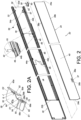
FIG. 2A is a perspective view of the working member of the slide rail assembly according to the embodiment of the present invention; -
FIG. 3 is a perspective view of the first rail of the slide rail assembly according to the embodiment of the present invention; -
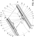
FIG. 4 is a schematic view showing that the second rail of the slide rail assembly according to the embodiment of the present invention is displaced in an opening direction with respect to the first rail; -
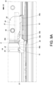
FIG. 4A is another schematic view showing that the second rail of the slide rail assembly according to the embodiment of the present invention is displaced in the opening direction with respect to the first rail; -
FIG. 5 is a schematic view showing that the second rail of the slide rail assembly is further displaced in the opening direction with respect to the first rail; -
FIG. 5A is another schematic view showing that the second rail of the slide rail assembly is further displaced in the opening direction with respect to the first rail; -
FIG. 6 is a schematic view showing that the second rail of the slide rail assembly is yet further displaced in the opening direction with respect to the first rail; -
FIG. 6A is another schematic view showing that the second rail of the slide rail assembly is yet further displaced in the opening direction with respect to the first rail; -
FIG. 7 shows that the first rail of the slide rail assembly according to the embodiment of the present invention is at an extended position with respect to the third rail, and that the second rail is moved out of the channel of the first rail in the opening direction; -
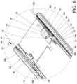
FIG. 8 is a schematic view showing that the second rail of the slide rail assembly is reinserted into the channel of the first rail in a retracting direction; -
FIG. 9 is a schematic view showing that the second rail of the slide rail assembly is further displaced in the retracting direction with respect to the first rail; -
FIG. 9A is another schematic view showing that the second rail of the slide rail assembly is further displaced in the retracting direction with respect to the first rail; -
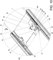
FIG. 10 is a schematic view showing that the second rail of the slide rail assembly is yet further displaced in the retracting direction with respect to the first rail; -
FIG. 10A is another schematic view showing that the second rail of the slide rail assembly is yet further displaced in the retracting direction with respect to the first rail; -
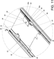
FIG. 11 is a schematic view showing that the second rail of the slide rail assembly is still further displaced in the retracting direction with respect to the first rail; and -
FIG. 11A is another schematic view showing that the second rail of the slide rail assembly is still further displaced in the retracting direction with respect to the first rail. - Referring to
FIG. 1 andFIG. 2 , theslide rail assembly 20 according to an embodiment of the present invention includes afirst rail 22, asecond rail 24, a slide-facilitatingdevice 26, a workingmember 28, and preferably also athird rail 30. Thefirst rail 22 is movably mounted between thethird rail 30 and thesecond rail 24, and thefirst rail 22 serves to increase the distance for which thesecond rail 24 can be displaced with respect to thethird rail 30. In this embodiment, the third rail 30 (e.g., an outer rail), the first rail 22 (e.g., a middle rail), and the second rail 24 (e.g., an inner rail) can be longitudinally displaced with respect to one another. Herein, the longitudinal direction (or the length direction of the slide rails) is defined by the X axis inFIG. 1 , the transverse direction (or the lateral direction of the slide rails) by the Y axis, and the vertical direction (or the height direction of the slide rails) by the Z axis. - The
first rail 22 includes achannel 32. Preferably, thefirst rail 22 includes afirst wall 34a, asecond wall 34b, and alongitudinal wall 36 connected between thefirst wall 34a and thesecond wall 34b of thefirst rail 22. Thefirst wall 34a, thesecond wall 34b, and thelongitudinal wall 36 of thefirst rail 22 jointly define thechannel 32. Thefirst rail 22 has afront end 22a and arear end 22b. - The
second rail 24 is movably mounted in thechannel 32 of thefirst rail 22, and thesecond rail 24 can be longitudinally displaced with respect to thefirst rail 22. Thesecond rail 24 includes afirst wall 38a, asecond wall 38b, and alongitudinal wall 40 connected between thefirst wall 38a and thesecond wall 38b of thesecond rail 24. Thesecond rail 24 includes a releasingfeature 37 such as a projection, and the releasingfeature 37 includes afirst guiding structure 39a and asecond guiding structure 39b. Each of thefirst guiding structure 39a and thesecond guiding structure 39b may be an inclined surface or a curved surface; the present invention has no limitation in this regard. Thesecond rail 24 has afront end 24a and arear end 24b, and the releasingfeature 37 is adjacent to therear end 24b of thesecond rail 24. - The slide-facilitating
device 26 is movably mounted between thefirst rail 22 and thesecond rail 24, and the slide-facilitatingdevice 26 includes anengaging feature 42 such as an engaging hook. Preferably, the slide-facilitatingdevice 26 further includes afirst portion 44a, asecond portion 44b, and alongitudinal portion 46 connected between thefirst portion 44a and thesecond portion 44b. Thefirst portion 44a, thesecond portion 44b, and thelongitudinal portion 46 correspond to thefirst wall 34a, thesecond wall 34b, and thelongitudinal wall 36 of thefirst rail 22 respectively. Each of thefirst portion 44a and thesecond portion 44b of the slide-facilitatingdevice 26 is provided with a plurality of rolling balls 48 (only the rollingballs 48 on thesecond portion 44b being visible inFIG. 1 andFIG. 2 due to limitations of the viewing angle). The rollingballs 48 on thefirst portion 44a are used to support thefirst wall 34a of thefirst rail 22 and thefirst wall 38a of thesecond rail 24, and the rollingballs 48 on thesecond portion 44b are used to support thesecond wall 34b of thefirst rail 22 and thesecond wall 38b of thesecond rail 24. The rollingballs 48 help increase the smoothness with which thesecond rail 24 and thefirst rail 22 can be displaced with respect to each other. - As shown in
FIG. 2 ,FIG. 3 , andFIG. 4 , the workingmember 28 is provided on thelongitudinal wall 36 of thefirst rail 22, and the workingmember 28 is adjacent to thefront end 22a of thefirst rail 22. The distance between the releasingfeature 37 and therear end 24b of thesecond rail 24 is greater (or slightly greater) than the distance between the workingmember 28 and thefront end 22a of thefirst rail 22. The workingmember 28 includes amain body portion 50, anelastic portion 52, and a predetermined portion 54 (seeFIG. 2A ). - Preferably, the working
member 28 is movably mounted on thelongitudinal wall 36 of thefirst rail 22. For example, themain body portion 50 of the workingmember 28 is pivotally connected to thelongitudinal wall 36 of thefirst rail 22 through ashaft 56; the present invention, however, has no limitation in this regard. - The
elastic portion 52, such as but not limited to an elastic arm, is configured to support themain body portion 50. Thepredetermined portion 54 is connected to themain body portion 50. - Preferably, the
longitudinal wall 36 of thefirst rail 22 is provided with a supportingportion 58 for supporting theelastic portion 52 of the working member 28 (seeFIG. 3 andFIG. 4 ). - Preferably, the
main body portion 50 of the workingmember 28 has two opposite ends defined respectively as a first end E1 and a second end E2, and thepredetermined portion 54 is adjacent to the first end E1 of the main body portion 50 (seeFIG. 2A ). - Preferably, the
elastic portion 52 of the workingmember 28 has afirst section 60a and asecond section 60b extending from thefirst section 60a. Thefirst section 60a is connected to themain body portion 50 and is adjacent to the second end E2 of themain body portion 50. Thesecond section 60b and themain body portion 50 define a predetermined space J therebetween (seeFIG. 2A ). When the workingmember 28 is in afirst state S 1, themain body portion 50 of the workingmember 28 and thesecond section 60b of theelastic portion 52 are spaced apart by a distance G due to the predetermined space J. - Preferably, the
predetermined portion 54 of the workingmember 28 includes afirst guiding feature 62, asecond guiding feature 64, and ahole 66 located between thefirst guiding feature 62 and thesecond guiding feature 64. Each of thefirst guiding feature 62 and thesecond guiding feature 64 may be an inclined surface or a curved surface. Thehole 66 is defined by a plurality of hole walls. For example, thepredetermined portion 54 includes afirst hole wall 68a, asecond hole wall 68b, athird hole wall 68c, and afourth hole wall 68d, and thehole walls FIG. 2A ). - Preferably, the
main body portion 50, theelastic portion 52, and thepredetermined portion 54 are integrated into one unit so that the workingmember 28 exists as a single component (seeFIG. 2A ). - Referring to
FIG. 4 , the engagingfeature 42 of the slide-facilitatingdevice 26 is located at thelongitudinal portion 46 and has a guidingsection 70, which may be an inclined surface or a curved surface. The workingmember 28 is shown inFIG. 4 as in thefirst state S 1, with the supportingportion 58 of thelongitudinal wall 36 of thefirst rail 22 supporting at least a portion of thesecond section 60b of theelastic portion 52 of the workingmember 28. In addition, thepredetermined portion 54 of the workingmember 28 is provided with anextension section 72 adjacent to thehole 66. For example, theextension section 72 extends from thefirst hole wall 68a toward thesecond wall 34b of thefirst rail 22. - When the
second rail 24 reaches a predetermined position after being displaced from a retracted position with respect to thefirst rail 22 in an opening direction D1, thefirst guiding structure 39a of the releasingfeature 37 contacts thefirst guiding feature 62 so that the releasingfeature 37 can move past thepredetermined portion 54 of the workingmember 28 with ease, and the slide-facilitatingdevice 26 will respond to the displacement of thesecond rail 24 by moving in theopening direction D 1 too, during which process the engaging feature 42 (or more particularly the guidingsection 70 thereof) of the slide-facilitatingdevice 26 contacts thefirst guiding feature 62 of thepredetermined portion 54 of the working member 28 (seeFIG. 4 andFIG. 4A ). The foregoing movements can be readily understood by a person of ordinary skill in the art and therefore will not be described in more detail. - Referring to
FIG. 5 andFIG. 5A , when thesecond rail 24 is further displaced in theopening direction D 1 with respect to thefirst rail 22, the contact between the engaging feature 42 (or more particularly the guidingsection 70 thereof) of the slide-facilitatingdevice 26 and thefirst guiding feature 62 of thepredetermined portion 54 of the workingmember 28 produces an action force that moves the workingmember 28 from thefirst stat S 1 to a second state S2, e.g., by pivoting the workingmember 28 from thefirst state S 1 to the second state S2 in a predetermined rotation direction R. Theelastic portion 52 of the workingmember 28 stores an elastic force in the second state S2. - Preferably, the mutual support between the supporting
portion 58 of thelongitudinal wall 36 of thefirst rail 22 and thesecond section 60b of theelastic portion 52 of the workingmember 28 creates a fulcrum around which the workingmember 28 can be pivoted from thefirst state S 1 to the second state S2, and in the course in which the workingmember 28 is pivoted to the second state S2, the predetermined space J allows themain body portion 50 of the workingmember 28 and thesecond section 60b of theelastic portion 52 to get closer to each other such that thefirst section 60a of theelastic portion 52 of the workingmember 28 is tilted up at a predetermined angle with respect to thesecond section 60b (or the supportingportion 58 of thelongitudinal wall 36 of the first rail 22), with the aforesaid elastic force stored in theelastic portion 52 of the workingmember 28. - Preferably, the working
member 28 further includes abent section 55 extending from the first end E1 of themain body portion 50, and thelongitudinal wall 36 of thefirst rail 22 is provided with acorresponding space 57 into which thebent section 55 can extend in order for thelongitudinal wall 36 of thefirst rail 22 to support thebent section 55 and thereby allow the workingmember 28 to move (e.g., pivot) stably. - Referring to
FIG. 6 ,FIG. 6A , andFIG. 7 , when thesecond rail 24 is moved out of thechannel 32 of thefirst rail 22 after being further displaced in theopening direction D 1 with respect to thefirst rail 22, the slide-facilitatingdevice 26 is displaced to a predetermined position K adjacent to thefront end 22a of thefirst rail 22, with theengaging feature 42 of the slide-facilitatingdevice 26 engaged with thehole 66 of thepredetermined portion 54 of the workingmember 28. - More specifically, when the slide-facilitating
device 26 reaches the predetermined position K, the engagingfeature 42 of the slide-facilitatingdevice 26 corresponds to thehole 66 of thepredetermined portion 54 such that theelastic portion 52 of the workingmember 28 releases the elastic force stored therein and thereby brings the workingmember 28 from the second state S2 back to the first state S1 (e.g., a locking state), with theengaging feature 42 of the slide-facilitatingdevice 26 extending into thehole 66 of thepredetermined portion 54 of the workingmember 28 and corresponding to thefirst hole wall 68a (and the extension section 72) to prevent the slide-facilitatingdevice 26 from arbitrary displacement with respect to thefirst rail 22. For example, thefirst hole wall 68a (together with the extension section 72) can block the engagingfeature 42 and thereby prevent the slide-facilitatingdevice 26 from being displaced from the predetermined position K in a retracting direction D2 with respect to the first rail 22 (seeFIG. 6 ). - In
FIG. 8 , the slide-facilitatingdevice 26 is at the predetermined position K, and the workingmember 28 is in the first state S1 (e.g., the locking state) to lock theengaging feature 42 of the slide-facilitatingdevice 26 in place. When thesecond rail 24 is reinserted into thechannel 32 of thefirst rail 22 from outside thechannel 32 of thefirst rail 22 in the retracting direction D2, thefirst wall 38a and thesecond wall 38b of thesecond rail 24 can, at the beginning of the insertion process, be supported respectively by the rollingballs 48 on the first and thesecond portions device 26 because the distance between the releasingfeature 37 and therear end 24b of thesecond rail 24 is greater (or slightly greater) than the distance between the workingmember 28 and thefront end 22a of thefirst rail 22, and this allows thesecond rail 24 to be inserted stably or smoothly into thechannel 32 of thefirst rail 22 in the retracting direction D2. - In the course in which the
second rail 24 continues being inserted into thechannel 32 of thefirst rail 22 in the retracting direction D2, referring toFIG. 9 ,FIG. 9A ,FIG. 10 ,FIG. 10A ,FIG. 11 , andFIG. 11A , the releasingfeature 37 of thesecond rail 24 moves the workingmember 28 and thereby disengages theengaging feature 42 of the slide-facilitatingdevice 26 from thehole 66 of thepredetermined portion 54 of the workingmember 28; in consequence, the slide-facilitatingdevice 26 is allowed to be displaced from the predetermined position K in the retracting direction D2. - More specifically, while the
second rail 24 continues being inserted into thechannel 32 of thefirst rail 22 in the retracting direction D2, thesecond guiding structure 39b of the releasingfeature 37 of thesecond rail 24 contacts thesecond guiding feature 64 of thepredetermined portion 54 of the workingmember 28 and thereby produces an action force that moves the workingmember 28 from the first state S1 (e.g., the locking state as shown inFIG. 9 andFIG. 9A ) to the second state S2 (e.g., an unlocking state as shown inFIG. 10 andFIG. 10A ), e.g., by pivoting the workingmember 28 from thefirst state S 1 to the second state S2 in the predetermined rotation direction R. As a result, the engagingfeature 42 of the slide-facilitatingdevice 26 is disengaged from thehole 66 of thepredetermined portion 54 of the workingmember 28. - Preferably, the mutual support between the supporting
portion 58 of thelongitudinal wall 36 of thefirst rail 22 and thesecond section 60b of theelastic portion 52 of the workingmember 28 creates a fulcrum around which the workingmember 28 can be pivoted from the first state S 1 (seeFIG. 9 andFIG. 9A ) to the second state S2 (seeFIG. 10 andFIG. 10A ), and in the course in which the workingmember 28 is pivoted to the second state S2, the predetermined space J allows themain body portion 50 of the workingmember 28 and thesecond section 60b of theelastic portion 52 to get closer to each other (seeFIG. 10 andFIG. 10A ) such that thefirst section 60a of theelastic portion 52 of the workingmember 28 is tilted up at a predetermined angle with respect to thesecond section 60b (or the supportingportion 58 of thelongitudinal wall 36 of the first rail 22), with an elastic force stored in theelastic portion 52 of the workingmember 28. - When the
second rail 24 is further displaced in the retracting direction D2 with respect to thefirst rail 22, the slide-facilitatingdevice 26 responds to the displacement of thesecond rail 24 by moving from the predetermined position K in the retracting direction D2, and theelastic portion 52 of the workingmember 28 releases the elastic force stored therein and thereby brings the workingmember 28 from the second state S2 (seeFIG. 10 andFIG. 10A ) back to the first state S 1 (seeFIG. 11 andFIG. 11A ). - It is worth mentioning that, referring to
FIG. 9 andFIG. 9A , thehole 66 of thepredetermined portion 54 is substantially larger in size than theengaging feature 42 of the slide-facilitatingdevice 26. More specifically, thefirst hole wall 68a and thesecond hole wall 68b define the longitudinal dimension of thehole 66 therebetween, and the longitudinal dimension of thehole 66 is substantially greater (or slightly greater) than the longitudinal dimension of the engaging feature 42 (e.g., an engaging hook) so that theengaging feature 42 can be received in thehole 66 with a predetermined degree of looseness. The predetermined degree of looseness allows theengaging feature 42 of the slide-facilitatingdevice 26 to be easily disengaged from thehole 66 of thepredetermined portion 54 of the workingmember 28 when the workingmember 28 is moved from thefirst state S 1 to the second state S2 by the releasing feature 37 (or more particularly thesecond guiding structure 39b thereof) of thesecond rail 24 in response to the insertion of thesecond rail 24 into thechannel 32 of thefirst rail 22 in the retracting direction D2. If theengaging feature 42 and thehole 66 are so sized that theengaging feature 42 and the hole walls (e.g., thefirst hole wall 68a and thesecond hole wall 68b) of thehole 66 may engage with each other too tightly to allow easy disengagement or may disengage from each other because of excessive tightness of engagement, the engagingfeature 42 of the slide-facilitatingdevice 26 and thepredetermined portion 54 of the workingmember 28 may be deformed or damaged as a result. - It can be known from the above that the
slide rail assembly 20 according to the foregoing embodiment of the present invention preferably has the following features: - 1. When the
predetermined portion 54 of the workingmember 28 is subjected to an external force (e.g., either of the action forces stated above), the external force can be mitigated by the movement (e.g., pivotal movement) of the workingmember 28 with respect to thefirst rail 22 and by the elasticity of theelastic portion 52 of the workingmember 28, lest thepredetermined portion 54 of the workingmember 28 be deformed by the external force. This helps increase the reliability in use of theslide rail assembly 20. - 2. The size of the
hole 66 of thepredetermined portion 54 is substantially larger than that of theengaging feature 42 of the slide-facilitatingdevice 26. - 3. The
main body portion 50, theelastic portion 52, and thepredetermined portion 54 may be integrated into one unit in order for the workingmember 28 to be a single component. - While the present invention has been disclosed by way of the preferred embodiment described above, the embodiment is not intended to be restrictive of the scope of the invention. The scope of the patent protection sought by the applicant is defined by the appended claims.
Claims (11)
- A slide rail assembly (20), comprising:a first rail (22) including a channel (32);a second rail (24) movably mounted in the channel (32) of the first rail (22), the second rail (24) being displaceable with respect to the first rail (22); anda slide-facilitating device (26) movably mounted between the first rail (22) and the second rail (24), the slide-facilitating device (26) including an engaging feature (42);
characterized inthat the slide rail assembly further comprising a working member (28) provided on the first rail (22), the working member (28) including a main body portion (50), an elastic portion (52), and a predetermined portion (54), wherein the elastic portion (52) is configured to support the main body portion (50), and the predetermined portion (54) is connected to the main body portion (50);wherein the first rail (22) is provided with a supporting portion (58) for supporting the elastic portion (52) of the working member (28);wherein when the second rail (24) is moved out of the channel (32) of the first rail (22) after displacement in an opening direction (D1) with respect to the first rail (22), the slide-facilitating device (26) is at a predetermined position (K), and the engaging feature (42) of the slide-facilitating device (26) is engaged with the predetermined portion (54) of the working member (28). - The slide rail assembly (20) as claimed in claim 1, wherein the first rail (22) includes a first wall (34a), a second wall (34b), and a longitudinal wall (36) connected between the first wall (34a) and the second wall (34b) of the first rail (22); and the first wall (34a), the second wall (34b), and the longitudinal wall (36) of the first rail (22) jointly define the channel (32).
- The slide rail assembly (20) as claimed in claim 2, wherein the working member (28) is movably mounted on the longitudinal wall (36) of the first rail (22).
- The slide rail assembly (20) as claimed in claim 2 or 3, wherein the main body portion (50) of the working member (28) is pivotally connected to the longitudinal wall (36) of the first rail (22).
- The slide rail assembly (20) as claimed in any one of claims 1-4, wherein the elastic portion (52) of the working member (28) has a first section (60a) and a second section (60b), the first section (60a) of the elastic portion (52) of the working member (28) is connected to the main body portion (50), and the second section (60b) of the elastic portion (52) of the working member (28) and the main body portion (50) of the working member (28) define a predetermined space (J) therebetween.
- The slide rail assembly (20) as claimed in any one of claims 1-5, wherein the predetermined portion (54) of the working member (28) includes a first guiding feature (62), a second guiding feature (64), and a hole (66) located between the first guiding feature (62) and the second guiding feature (64), the hole (66) is defined by a plurality of hole walls (68a, 68b, 68c, 68d), and the hole (66) is configured for engagement with the engaging feature (42) of the slide-facilitating device (26).
- The slide rail assembly (20) as claimed in claim 6, wherein the hole (66) is substantially larger in size than the engaging feature (42).
- The slide rail assembly (20) as claimed in claim 6 or 7, wherein the second rail (24) includes a releasing feature (37); while the second rail (24) is being reinserted into the channel (32) of the first rail (22) from outside the channel (32) of the first rail (22) in a retracting direction (D2), the releasing feature (37) of the second rail (22) contacts one of the first guiding feature (62) and the second guiding feature (64) and thereby moves the working member (28) such that the engaging feature (42) of the slide-facilitating device (26) is disengaged from the hole (66) of the predetermined portion (54) of the working member (28) to allow the slide-facilitating device (26) to be displaced from the predetermined position (K) in the retracting direction (D2); the second rail (24) has a front end (24a) and a rear end (24b); the releasing feature (37) is adjacent to the rear end (24b) of the second rail (24); the first rail (22) has a front end (22a) and a rear end (22b); the working member (28) is adjacent to the front end (22a) of the first rail (22); and a distance between the releasing feature (37) and the rear end (24b) of the second rail (24) is greater or slightly greater than a distance between the working member (28) and the front end (22a) of the first rail (22).
- The slide rail assembly (20) as claimed in any one of claims 6-8, wherein the engaging feature (42) of the slide-facilitating device (26) is configured to extend into the hole (66) of the predetermined portion (54) of the working member (28) to prevent the slide-facilitating device (26) from arbitrary displacement with respect to the first rail (22); and wherein the predetermined portion (54) of the working member (28) is provided with an extension section (72) adjacent to the hole (66), and the engaging feature (42) of the slide-facilitating device (26) corresponds to the extension section (72) when extending into the hole (66) of the predetermined portion (54) of the working member (28).
- The slide rail assembly (20) as claimed in any one of claims 2-9, wherein the slide-facilitating device (26) further includes a first portion (44a), a second portion (44b), and a longitudinal portion (46) connected between the first portion (44a) and the second portion (44b); the first portion (44a), the second portion (44b), and the longitudinal portion (46) correspond to the first wall (34a), the second wall (34b), and the longitudinal wall (36) of the first rail (22) respectively; the first portion (44a) of the slide-facilitating device (26) is provided with a plurality of rolling balls (48) for supporting the first wall (34a) of the first rail (22); and the second portion (44b) of the slide-facilitating device (26) is provided with a plurality of rolling balls (48) for supporting the second wall (34b) of the first rail (22).
- The slide rail assembly (20) as claimed in any one of claims 1-10, wherein the engaging feature (42) of the slide-facilitating device (26) is an engaging hook.
Applications Claiming Priority (1)
| Application Number | Priority Date | Filing Date | Title |
|---|---|---|---|
| TW111139169A TWI815701B (en) | 2022-10-13 | 2022-10-13 | Slide rail assembly |
Publications (2)
| Publication Number | Publication Date |
|---|---|
| EP4353127A1 true EP4353127A1 (en) | 2024-04-17 |
| EP4353127B1 EP4353127B1 (en) | 2025-05-14 |
Family
ID=85873829
Family Applications (1)
| Application Number | Title | Priority Date | Filing Date |
|---|---|---|---|
| EP23166431.9A Active EP4353127B1 (en) | 2022-10-13 | 2023-04-04 | Slide rail assembly |
Country Status (4)
| Country | Link |
|---|---|
| US (1) | US20240122342A1 (en) |
| EP (1) | EP4353127B1 (en) |
| JP (1) | JP7442714B1 (en) |
| TW (1) | TWI815701B (en) |
Families Citing this family (2)
| Publication number | Priority date | Publication date | Assignee | Title |
|---|---|---|---|---|
| US12324515B2 (en) * | 2023-04-11 | 2025-06-10 | Martas Precision Slide Co., Ltd. | Middle and inner rails synchronization mechanism of slide rail |
| TWI862445B (en) * | 2024-04-12 | 2024-11-11 | 川湖科技股份有限公司 | Slide rail assembly |
Citations (4)
| Publication number | Priority date | Publication date | Assignee | Title |
|---|---|---|---|---|
| US20020081887A1 (en) * | 2000-12-22 | 2002-06-27 | Judge Ronald J. | Controller for a quick disconnect slide assembly |
| US6851773B2 (en) | 2003-04-15 | 2005-02-08 | King Slide Works Co., Ltd. | Retaining structure for a slide-aiding member of a track device for a drawer |
| US7648214B2 (en) | 2005-05-02 | 2010-01-19 | King Slide Works Co., Ltd. | Positioning device for drawer slide bearing carrier |
| US8752917B1 (en) * | 2013-01-03 | 2014-06-17 | Gslide Corporation | Ball bushing positioning structure of a sliding rail assembly for server |
Family Cites Families (5)
| Publication number | Priority date | Publication date | Assignee | Title |
|---|---|---|---|---|
| TWM453419U (en) * | 2012-11-22 | 2013-05-21 | Dynaslide Corp | Ball sleeve positioning device of sliding rail for server |
| TWI706752B (en) * | 2019-11-18 | 2020-10-11 | 川湖科技股份有限公司 | Slide rail assembly |
| TWI712380B (en) * | 2020-05-12 | 2020-12-11 | 川湖科技股份有限公司 | Slide rail assembly and rails mounting method thereof |
| US11607040B2 (en) * | 2020-06-30 | 2023-03-21 | King Slide Works Co., Ltd | Slide rail assembly |
| TWI717306B (en) * | 2020-08-19 | 2021-01-21 | 川湖科技股份有限公司 | Slide rail assembly |
-
2022
- 2022-10-13 TW TW111139169A patent/TWI815701B/en active
-
2023
- 2023-03-27 US US18/190,376 patent/US20240122342A1/en not_active Abandoned
- 2023-04-04 EP EP23166431.9A patent/EP4353127B1/en active Active
- 2023-04-11 JP JP2023063842A patent/JP7442714B1/en active Active
Patent Citations (4)
| Publication number | Priority date | Publication date | Assignee | Title |
|---|---|---|---|---|
| US20020081887A1 (en) * | 2000-12-22 | 2002-06-27 | Judge Ronald J. | Controller for a quick disconnect slide assembly |
| US6851773B2 (en) | 2003-04-15 | 2005-02-08 | King Slide Works Co., Ltd. | Retaining structure for a slide-aiding member of a track device for a drawer |
| US7648214B2 (en) | 2005-05-02 | 2010-01-19 | King Slide Works Co., Ltd. | Positioning device for drawer slide bearing carrier |
| US8752917B1 (en) * | 2013-01-03 | 2014-06-17 | Gslide Corporation | Ball bushing positioning structure of a sliding rail assembly for server |
Also Published As
| Publication number | Publication date |
|---|---|
| EP4353127B1 (en) | 2025-05-14 |
| TWI815701B (en) | 2023-09-11 |
| JP2024058550A (en) | 2024-04-25 |
| TW202415319A (en) | 2024-04-16 |
| JP7442714B1 (en) | 2024-03-04 |
| US20240122342A1 (en) | 2024-04-18 |
Similar Documents
| Publication | Publication Date | Title |
|---|---|---|
| EP4353127B1 (en) | Slide rail assembly | |
| KR100473100B1 (en) | Self-closing slide and mechanism for a self-closing slide | |
| EP4349220A1 (en) | Slide rail assembly | |
| US7210198B2 (en) | Retracting apparatus, drawer apparatus and sliding door apparatus | |
| US5551775A (en) | Telescopic drawer slide with mechanical sequencing latch | |
| US7090319B2 (en) | Guide tab and slide incorporating the same | |
| EP4570126A1 (en) | Slide rail assembly | |
| US6971729B1 (en) | Self-closing slide | |
| JP2001516254A (en) | Improved drawer slide | |
| US4858272A (en) | Door closing device | |
| EP0346050A1 (en) | Folding door structure | |
| JP4690026B2 (en) | Slide assist device for moving objects | |
| EP2853667B1 (en) | Hinge device | |
| JP3084767U (en) | Front tension lock structure for rail | |
| US20130221822A1 (en) | Slide assembly | |
| CN116234966B (en) | Extension lock for drawers | |
| CN221277502U (en) | Corner hinge | |
| EP3714123B1 (en) | Lifting device including a sledge system axle and a roof window comprising such a lifting device | |
| JP2018127776A (en) | Closer for sliding door | |
| US6167781B1 (en) | System and apparatus for retaining position of cam follower | |
| EP4226006B1 (en) | A door hinge for household appliances | |
| HU223550B1 (en) | Closing apparatus, particularly lock for doors and windows | |
| EP0911208A1 (en) | Seat slide apparatus | |
| JP3614201B2 (en) | Drawer double suspension system | |
| JP2585878Y2 (en) | Expansion joint cover holding device |
Legal Events
| Date | Code | Title | Description |
|---|---|---|---|
| PUAI | Public reference made under article 153(3) epc to a published international application that has entered the european phase |
Free format text: ORIGINAL CODE: 0009012 |
|
| STAA | Information on the status of an ep patent application or granted ep patent |
Free format text: STATUS: REQUEST FOR EXAMINATION WAS MADE |
|
| 17P | Request for examination filed |
Effective date: 20240206 |
|
| AK | Designated contracting states |
Kind code of ref document: A1 Designated state(s): AL AT BE BG CH CY CZ DE DK EE ES FI FR GB GR HR HU IE IS IT LI LT LU LV MC ME MK MT NL NO PL PT RO RS SE SI SK SM TR |
|
| GRAP | Despatch of communication of intention to grant a patent |
Free format text: ORIGINAL CODE: EPIDOSNIGR1 |
|
| STAA | Information on the status of an ep patent application or granted ep patent |
Free format text: STATUS: GRANT OF PATENT IS INTENDED |
|
| INTG | Intention to grant announced |
Effective date: 20241106 |
|
| GRAS | Grant fee paid |
Free format text: ORIGINAL CODE: EPIDOSNIGR3 |
|
| GRAA | (expected) grant |
Free format text: ORIGINAL CODE: 0009210 |
|
| STAA | Information on the status of an ep patent application or granted ep patent |
Free format text: STATUS: THE PATENT HAS BEEN GRANTED |
|
| AK | Designated contracting states |
Kind code of ref document: B1 Designated state(s): AL AT BE BG CH CY CZ DE DK EE ES FI FR GB GR HR HU IE IS IT LI LT LU LV MC ME MK MT NL NO PL PT RO RS SE SI SK SM TR |
|
| REG | Reference to a national code |
Ref country code: GB Ref legal event code: FG4D |
|
| REG | Reference to a national code |
Ref country code: CH Ref legal event code: EP |
|
| REG | Reference to a national code |
Ref country code: IE Ref legal event code: FG4D |
|
| REG | Reference to a national code |
Ref country code: DE Ref legal event code: R096 Ref document number: 602023003425 Country of ref document: DE |
|
| REG | Reference to a national code |
Ref country code: NL Ref legal event code: MP Effective date: 20250514 |
|
| PG25 | Lapsed in a contracting state [announced via postgrant information from national office to epo] |
Ref country code: PT Free format text: LAPSE BECAUSE OF FAILURE TO SUBMIT A TRANSLATION OF THE DESCRIPTION OR TO PAY THE FEE WITHIN THE PRESCRIBED TIME-LIMIT Effective date: 20250915 Ref country code: FI Free format text: LAPSE BECAUSE OF FAILURE TO SUBMIT A TRANSLATION OF THE DESCRIPTION OR TO PAY THE FEE WITHIN THE PRESCRIBED TIME-LIMIT Effective date: 20250514 Ref country code: ES Free format text: LAPSE BECAUSE OF FAILURE TO SUBMIT A TRANSLATION OF THE DESCRIPTION OR TO PAY THE FEE WITHIN THE PRESCRIBED TIME-LIMIT Effective date: 20250514 |
|
| REG | Reference to a national code |
Ref country code: LT Ref legal event code: MG9D |
|
| PG25 | Lapsed in a contracting state [announced via postgrant information from national office to epo] |
Ref country code: NO Free format text: LAPSE BECAUSE OF FAILURE TO SUBMIT A TRANSLATION OF THE DESCRIPTION OR TO PAY THE FEE WITHIN THE PRESCRIBED TIME-LIMIT Effective date: 20250814 Ref country code: GR Free format text: LAPSE BECAUSE OF FAILURE TO SUBMIT A TRANSLATION OF THE DESCRIPTION OR TO PAY THE FEE WITHIN THE PRESCRIBED TIME-LIMIT Effective date: 20250815 |
|
| PG25 | Lapsed in a contracting state [announced via postgrant information from national office to epo] |
Ref country code: NL Free format text: LAPSE BECAUSE OF FAILURE TO SUBMIT A TRANSLATION OF THE DESCRIPTION OR TO PAY THE FEE WITHIN THE PRESCRIBED TIME-LIMIT Effective date: 20250514 Ref country code: PL Free format text: LAPSE BECAUSE OF FAILURE TO SUBMIT A TRANSLATION OF THE DESCRIPTION OR TO PAY THE FEE WITHIN THE PRESCRIBED TIME-LIMIT Effective date: 20250514 |
|
| REG | Reference to a national code |
Ref country code: AT Ref legal event code: MK05 Ref document number: 1794059 Country of ref document: AT Kind code of ref document: T Effective date: 20250514 |
|
| PG25 | Lapsed in a contracting state [announced via postgrant information from national office to epo] |
Ref country code: BG Free format text: LAPSE BECAUSE OF FAILURE TO SUBMIT A TRANSLATION OF THE DESCRIPTION OR TO PAY THE FEE WITHIN THE PRESCRIBED TIME-LIMIT Effective date: 20250514 |
|
| PG25 | Lapsed in a contracting state [announced via postgrant information from national office to epo] |
Ref country code: HR Free format text: LAPSE BECAUSE OF FAILURE TO SUBMIT A TRANSLATION OF THE DESCRIPTION OR TO PAY THE FEE WITHIN THE PRESCRIBED TIME-LIMIT Effective date: 20250514 |
|
| PG25 | Lapsed in a contracting state [announced via postgrant information from national office to epo] |
Ref country code: AT Free format text: LAPSE BECAUSE OF FAILURE TO SUBMIT A TRANSLATION OF THE DESCRIPTION OR TO PAY THE FEE WITHIN THE PRESCRIBED TIME-LIMIT Effective date: 20250514 |
|
| PG25 | Lapsed in a contracting state [announced via postgrant information from national office to epo] |
Ref country code: RS Free format text: LAPSE BECAUSE OF FAILURE TO SUBMIT A TRANSLATION OF THE DESCRIPTION OR TO PAY THE FEE WITHIN THE PRESCRIBED TIME-LIMIT Effective date: 20250814 |
|
| PG25 | Lapsed in a contracting state [announced via postgrant information from national office to epo] |
Ref country code: IS Free format text: LAPSE BECAUSE OF FAILURE TO SUBMIT A TRANSLATION OF THE DESCRIPTION OR TO PAY THE FEE WITHIN THE PRESCRIBED TIME-LIMIT Effective date: 20250914 |
|
| PG25 | Lapsed in a contracting state [announced via postgrant information from national office to epo] |
Ref country code: LV Free format text: LAPSE BECAUSE OF FAILURE TO SUBMIT A TRANSLATION OF THE DESCRIPTION OR TO PAY THE FEE WITHIN THE PRESCRIBED TIME-LIMIT Effective date: 20250514 |
|
| PG25 | Lapsed in a contracting state [announced via postgrant information from national office to epo] |
Ref country code: DK Free format text: LAPSE BECAUSE OF FAILURE TO SUBMIT A TRANSLATION OF THE DESCRIPTION OR TO PAY THE FEE WITHIN THE PRESCRIBED TIME-LIMIT Effective date: 20250514 Ref country code: SM Free format text: LAPSE BECAUSE OF FAILURE TO SUBMIT A TRANSLATION OF THE DESCRIPTION OR TO PAY THE FEE WITHIN THE PRESCRIBED TIME-LIMIT Effective date: 20250514 |
|
| PG25 | Lapsed in a contracting state [announced via postgrant information from national office to epo] |
Ref country code: CZ Free format text: LAPSE BECAUSE OF FAILURE TO SUBMIT A TRANSLATION OF THE DESCRIPTION OR TO PAY THE FEE WITHIN THE PRESCRIBED TIME-LIMIT Effective date: 20250514 |
|
| PG25 | Lapsed in a contracting state [announced via postgrant information from national office to epo] |
Ref country code: EE Free format text: LAPSE BECAUSE OF FAILURE TO SUBMIT A TRANSLATION OF THE DESCRIPTION OR TO PAY THE FEE WITHIN THE PRESCRIBED TIME-LIMIT Effective date: 20250514 |
|
| PG25 | Lapsed in a contracting state [announced via postgrant information from national office to epo] |
Ref country code: SK Free format text: LAPSE BECAUSE OF FAILURE TO SUBMIT A TRANSLATION OF THE DESCRIPTION OR TO PAY THE FEE WITHIN THE PRESCRIBED TIME-LIMIT Effective date: 20250514 |
|
| PG25 | Lapsed in a contracting state [announced via postgrant information from national office to epo] |
Ref country code: IT Free format text: LAPSE BECAUSE OF FAILURE TO SUBMIT A TRANSLATION OF THE DESCRIPTION OR TO PAY THE FEE WITHIN THE PRESCRIBED TIME-LIMIT Effective date: 20250514 |
|
| REG | Reference to a national code |
Ref country code: DE Ref legal event code: R097 Ref document number: 602023003425 Country of ref document: DE |
|
| PLBE | No opposition filed within time limit |
Free format text: ORIGINAL CODE: 0009261 |
|
| STAA | Information on the status of an ep patent application or granted ep patent |
Free format text: STATUS: NO OPPOSITION FILED WITHIN TIME LIMIT |
|
| REG | Reference to a national code |
Ref country code: CH Ref legal event code: L10 Free format text: ST27 STATUS EVENT CODE: U-0-0-L10-L00 (AS PROVIDED BY THE NATIONAL OFFICE) Effective date: 20260325 |
|
| PGFP | Annual fee paid to national office [announced via postgrant information from national office to epo] |
Ref country code: IE Payment date: 20260320 Year of fee payment: 4 |
|
| 26N | No opposition filed |
Effective date: 20260217 |