US4858272A - Door closing device - Google Patents
Door closing device Download PDFInfo
- Publication number
- US4858272A US4858272A US07/160,383 US16038388A US4858272A US 4858272 A US4858272 A US 4858272A US 16038388 A US16038388 A US 16038388A US 4858272 A US4858272 A US 4858272A
- Authority
- US
- United States
- Prior art keywords
- door
- slider
- clutch member
- guide rail
- clutch
- Prior art date
- Legal status (The legal status is an assumption and is not a legal conclusion. Google has not performed a legal analysis and makes no representation as to the accuracy of the status listed.)
- Expired - Fee Related
Links
Images


Classifications
-
- E—FIXED CONSTRUCTIONS
- E05—LOCKS; KEYS; WINDOW OR DOOR FITTINGS; SAFES
- E05F—DEVICES FOR MOVING WINGS INTO OPEN OR CLOSED POSITION; CHECKS FOR WINGS; WING FITTINGS NOT OTHERWISE PROVIDED FOR, CONCERNED WITH THE FUNCTIONING OF THE WING
- E05F3/00—Closers or openers with braking devices, e.g. checks; Construction of pneumatic or liquid braking devices
- E05F3/22—Additional arrangements for closers, e.g. for holding the wing in opened or other position
- E05F3/221—Mechanical power-locks, e.g. for holding the wing open or for free-moving zones
-
- E—FIXED CONSTRUCTIONS
- E05—LOCKS; KEYS; WINDOW OR DOOR FITTINGS; SAFES
- E05Y—INDEXING SCHEME RELATING TO HINGES OR OTHER SUSPENSION DEVICES FOR DOORS, WINDOWS OR WINGS AND DEVICES FOR MOVING WINGS INTO OPEN OR CLOSED POSITION, CHECKS FOR WINGS AND WING FITTINGS NOT OTHERWISE PROVIDED FOR, CONCERNED WITH THE FUNCTIONING OF THE WING
- E05Y2900/00—Application of doors, windows, wings or fittings thereof
- E05Y2900/10—Application of doors, windows, wings or fittings thereof for buildings or parts thereof
- E05Y2900/13—Application of doors, windows, wings or fittings thereof for buildings or parts thereof characterised by the type of wing
- E05Y2900/132—Doors
Definitions
- This invention relates to a door closing device for reinforcing a closing force when a door is closed.
- a type of door closing device in which a door closer main body is fixed to a vertical portion of a door frame and in which a guide rail is fixed to an upper portion of the door.
- the door closing device restricts the opening movement of the door when opened and exerts a closing or latching force on the door when the door is released.
- a slide member is slidably held by the guide rail and urged by a tension spring in the direction where the door is closed.
- the slide member is rotatably connected to the door closer main body through a connecting arm.
- the tension spring is generally provided along the guide rail.
- the tension spring is expanded or compressed through a total stroke of the door opening and closing movements. Therefore, the tension spring is expanded for a relatively long distance. This requires a substantially large spring to assure durability. Further, the reliability of the door closing device is decreased. In addition, the size of the guide rail must be increased.
- an improved door closing device for reinforcing the door closing or latching force before a door is completely closed, which comprises: a door closer main body for restricting a swinging motion of the door when the door is opened and exerting closing force on the door when the door is closed; a guide rail provided on the door for guiding a slider there along, an arm for connecting a main axis of the door closer main body with the slider; a tension spring provided in the guide rail for additionally exerting a closing force on the door; a releasably connecting means for releasably connecting the tension spring with the slider when the door is swung to a certain angular position near a position where the door is completely closed.
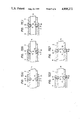
- FIG. 1 is a vertical longitudinal view of an improved door closing device according to a first embodiment of this invention
- FIG. 2 is a bottom view of an improved door closing device according to a first embodiment of this invention
- FIGS. 3(A)(B)(C) and (D) are vertical longitudinal views of the improved door closing device for explaining the operation of the device in order, respectively;
- FIG. 4 is a horizontal longitudinal view of the improved supplemental door closing device according to a second embodiment of this invention.
- FIG. 5 is a vertical longitudinal view of the improved door closing device according to a second embodiment of this invention.
- FIG. 6(A)(B)(C) and (D) are horizontal longitudinal views of the improved door closing device for explaining the operation of the device in order, respectively;
- FIGS. 7(A)(B)(C)(D) and (E) are horizontal sectional views for explaining, in order, a state of engagement of rollers and recesses in a region of a door opening stroke;
- FIG. 8(A) is plan view of a conventional door closing device
- FIG. 8(B) is a side view of the conventional door closing device.
- a conventional door closing device will be first presented below with reference to FIG. 8(A) and 8(B) principally for the purpose of comparison therebetween.
- the main body 101 of a door closer is fixed to a vertical frame 103 while a guide rail 102 is fixed to a door 104.
- the manner of fixing the main body 101 and the guide rail 102 is in contrast with that of a conventional door closer.
- An arm 105 connects the main axis 106 of the door closer with a slider S of the guide rail 102 through a pin 7a.
- the slider S is connected to a tension spring 107 which is expanded and compressed when the door 104 is opened and closed, respectively.
- the slider S is always connected to the spring 107 through a total stroke of the door and is relatively large. Therefore, the spring 107 must be strong and relatively large.
- An improved door closing device comprises a conventional door closer main body 101 as shown in FIGS. 8(A) and 8(B), and conventional connecting arm as shown in FIG. 8(A) and 8(B) whose one end is connected to one end of the door closer main body 101.
- the improved door closing device further includes a slider 4 connected to the other end of the arm, a tension spring 9, a releasably connecting mechanism M 1 for releasably connecting the slider 4 with the spring 9 and a guide rail 1 for guiding the slider 4.
- the guide rail 1 has an elongated shape in which a slit is provided at its lower face for guiding a pin 7a connecting the slider 4 with the arm. Opposite ends of the guide rail 1 are provided with two end caps 2,3 which have two fixing pins 2a, 3a for fixing the guide rail 1 to the door, respectively.
- the fixing pin 3a holds one end of the tension spring 9.
- the guide rail 1 has a stopping hole 1b on its top rail 1a near the left end of the guide rail 1 as viewed in FIG. 1.
- the slider 4 is slidably accommodated in the guide rail 1 and the pin 7a is fixed to the slider 4 through a washer 7c and a screw 7b.
- the main axis of the door closer main body is connected to the pin 7a through the arm (not shown).
- the slider 4 slides the length of the guide rail 1 corresponding to the opening and closing operation of the door.
- the slider 4 has at one end thereof an engaging projection 4a facing upward.
- the releasably connecting mechanism M 1 has a first plate-like clutch member 8 which is slidably accommodated in the guide rail 1 along a sliding face of the top wall 1a.
- the other end of the tension spring 9 is hooked at a hook 8a formed at the left end of the first clutch member 8.
- the tension spring 9 urges the first clutch member 8 in the left direction, as viewed in FIG. 1.
- the first clutch member 8 has a through hole 8b for loosely receiving a stop ball 10.
- the through hole 8b is located at a position deviated in the leftward direction from the stop hole 1b of the guide rail 1 by a certain distance when the door is completely closed, as shown in FIGS. 1. 2 and 3.
- the second clutch member 11 has a deep groove 11a and a shallow groove 11b, at its upper face opposite to the lower face of the first clutch member 8, disposed successively in the longitudinal direction of the guide rail 1 so that the stop ball 10 can be moved in the same direction.
- a step 11c for pushing the stop ball 10 into the through hole 8b and for dropping it onto the deep groove 11a.
- the second clutch member 11 has a recess 11d on its right side, as viewed in FIG. 2, for receiving the third clutch member 12 swingably about a pivot pin 13 extending horizontally. The opposite ends of the pivot pin 13 are fixed to the opposite sides of the second clutch member 11.
- the third clutch member 12 has, at its front end, an engaging projection 12a facing downward which detachably engages with the engaging projection 4a of the slider 4.
- the second clutch member 11 has on its front wall facing the rear wall face of the third clutch member 12, a recess 11e for receiving a compression spring 14.
- the compression spring 14, in FIG. 1 urges the third clutch member 12 to rotate, about the pin 13, in the counterclockwise direction, that is, a direction where the third clutch member 12 releases the slider 4 therefrom.
- the third clutch member 12 is, as shown in FIGS. 1 and 3(A), prevented from rotating by abutting against the front (right) end of the first clutch member 8.
- the third clutch member 12 is slid forward (right direction) by the slider 4 through a certain stroke.
- the third clutch member 12 is rotated by the spring force of the compression spring 14 and the tensile force of the slider 4 in the counterclockwise direction thereby to release the slider 4 therefrom.
- the first, second and third clutch members 8, 11 and 12, respectively, operate in the following manner.
- the three clutch members are moved forward for a certain stroke together with the slider 4 while expanding the tension spring 9. Then, they are released from the slider 4. With the tension spring 9 expanded, the stop ball 10 comes into the stopping hole 1b to keep the three clutch members at a position during the opening movement of the door.
- FIG. 3(A) shows a state wherein the door is closed.
- the first clutch member 8 is pulled by the tension spring 9 in the left direction as viewed in FIG. 3(A) and the slider 4 is held by the arm (not shown) at a predetermined position. Therefore, at this time, the first, second and third clutch members 8, 11 and 12, respectively, are held on the left side of the guide rail 1 as viewed in FIG. 3(A).
- the second clutch member 11 is moved for the length of the shallow groove 11b in the right direction relative to the first clutch member 8 to release the restriction of the rotation of the third clutch member 12. Therefore, the third clutch member 12 is, as shown in FIG. 3(C), rotated by the pushing force of the compression spring 14 and the tensile force of the slider 4 to thereby release the engagement of the third clutch member 12 and the slider 4. Therefore, the slider 4 can be slid freely in the right direction as shown in FIG. 3(C) while the door is further opened.
- the third clutch member 12 and the second clutch member 11 are slid in the left direction with respect to the first clutch member 8.
- the stop ball 10 is dropped from the shallow groove 11b onto the deep groove 11a, so that the stop ball 10 comes out of the stopping hole 1b. Therefore, the first clutch member 8 is released from the guide rail 1 and the three clutch members and the slider 4 are pulled by the stored additional door closing force in the left direction together.
- the door closing force is reinforced by the stored force of the tension spring 9.
- a guide rail 1 has a slider 5 slidable in the longitudinal direction of the guide rail 1.
- the slider 5 is connected to the arm pin 7a.
- the slider 5 cooperates with a releasably connecting mechanism M 2 for releasably connecting the slider 5 with the tension spring 9.
- the mechanism M 2 comprises a connecting plate 15 for connecting the slider 5 with the tension spring 9 through an auxiliary slider 6.
- the right (front) end of the connecting plate 15 is pivotably connected to the arm pin 7a through a washer 7c and a screw 7b.
- the connecting plate 15 is extended, for approximately half the length of the guide rail 1, toward the right (rear) side of the guide rail.
- the roller receiving member 16 has a U-shaped cross section in which the auxiliary slider 6 is held slidably in the same direction as that of the slider 5.
- the auxiliary slider 6 has a flat rectangular hole 6a extending therethrough in the longitudinal direction of the slider 6 and the connecting plate 15 slidably passes through the hole 6a.
- the auxiliary slider 6 is elastically urged by the tension spring 9 to the left (rear) side.
- the rear end of the spring 9 is hooked on the fixing pin 3a fixed to the end cap 3 while the front end of the spring 9 is fixed to the rear end of the auxiliary slider 6.
- the auxiliary slider 6 has, at its two side walls 6b, 6b, a pair of notched spaces 17,17 opposite to each other which are connected to each other in the lateral direction of the guide rail 1.
- a roller 18 extending vertically so as to be freely rotatably movable in the lateral direction.
- the diameter of each roller 18 must have a diameter larger than the thickness of each side wall 6b of the auxiliary slider 6.
- the connecting plate 15 is provided, at its two side walls, with a pair of engaging recesses 19,19 opposite to each other for receiving the rollers 18 in a state wherein the outer surface of each roller 18 abuts against the inner face of each of the two side walls 16a, 16a of the roller receiving member 16 when the door is closed as shown in FIGS. 4 and 5.
- On the inner walls of the left and right side walls 16a of the roller receiving member 16 are formed a pair of engaging recesses 20,20 opposite to each other for receiving the rollers 18, respectively, when the door is opened to a predetermined angular position.
- the engaging recesses 19 of the connecting plate 15 are in registration with the engaging recesses 20, respectively. That is, the distance 1 between the projection 6c and the recess 16b is equal to a slide stroke 1 of the auxiliary slider 6 between the space 17 and the engaging recess 20 when the door is closed or opened.
- the connecting plate 15 has, at a position near its rear end and its two lateral sides, a pair of engaging recesses 21,21 whose depth is smaller than that of the engaging recesses 19.
- the engaging recesses 21, cooperating with the rollers 18, function to temporarily stop a continuous opening movement of the door shortly before the door is completely opened. That is, each roller 18 engages each engaging recess 21 of the connecting plate 15 to stop the continuous opening operation of the door shortly before the door is fully opened, whereby the door can be stopped smoothly at its final step without impact.
- Each of the above recesses 19,20,21 may have approximately semicircular shape to assure a smooth engagement and release between each roller and each recess.
- Two spherical balls may be used instead of the two rollers 18.
- the slider 5 When the door is gradually opened from the completely closed condition, the slider 5 is slid forward (in the right direction as viewed in the drawings) by the swinging motion of the arm 104 shown in FIGS. 8(A) and (B). At this time the slider 5 is slid through the stroke 1 in the forward direction together with the auxiliary slider 6 while expanding the tension spring 9 because the connecting plate 15 and the auxiliary slider 6 are united with each other through the engagement of each roller 18 and each engaging recess 19 of the connecting plate 15. This results in storing a door closing force in the tension spring 9.
- rollers 18 When the rollers 18 reach a position where the engaging recesses 20 are located, the rollers 18 disengage engaging recesses 19 due to a sliding force of the auxiliary slider 6 and the connecting plate 15, to thereby engage with the engaging recess 20, as shown in FIG. 6(A).
- FIGS. 7(A) to 7(E) The state of the movement of the rollers 18 and the engagement of the rollers 18 with the engaging recesses 19, 20 are described in FIGS. 7(A) to 7(E). That is, when each roller 18 is located to the left of each engaging recess 20, the roller 18, received in the engaging recess 19 and the space 17, rotates on the inner surface of the roller receiving member 16, as shown in FIG. 7(A). Then as the roller 18 comes near a position where the roller 18 completely registers with the engaging recess 20, the roller 18 is pushed laterally outwardly by the curved surface of the engaging recess 19, as shown in FIGS. 7(B) and (C).
- each rear engaging recess 21 is relatively shallow, if the slider 5 is pushed further, each roller 18 can easily come out of the recess 21 to open the door further. Then, when the door is fully opened as shown in FIG. 6(D). the slider 5 abuts against the end cap 2 to stop the opening of the door.
- the improved door closing device is so formed that a door closing force is additionally exerted on a door only in a region for which a latching force is necessary. Therefore, the durability of a tension spring can be increased while the size of the tension spring and the guide rail can be decreased. Further, as the door is opened freely through the region of the door opening movement after the slider is released from the tension spring, the opening operation of the door can be easily and smoothly carried out without a large force in comparison with a conventional device.
Abstract
Description
Claims (6)
Applications Claiming Priority (4)
| Application Number | Priority Date | Filing Date | Title |
|---|---|---|---|
| JP1154687U JPS63121340U (en) | 1987-01-30 | 1987-01-30 | |
| JP8597887U JPH0448309Y2 (en) | 1987-06-01 | 1987-06-01 | |
| JP62-85978[U] | 1987-06-01 | ||
| JP62-11546[U] | 1987-07-27 |
Publications (1)
| Publication Number | Publication Date |
|---|---|
| US4858272A true US4858272A (en) | 1989-08-22 |
Family
ID=26346989
Family Applications (1)
| Application Number | Title | Priority Date | Filing Date |
|---|---|---|---|
| US07/160,383 Expired - Fee Related US4858272A (en) | 1987-01-30 | 1988-02-25 | Door closing device |
Country Status (1)
| Country | Link |
|---|---|
| US (1) | US4858272A (en) |
Cited By (14)
| Publication number | Priority date | Publication date | Assignee | Title |
|---|---|---|---|---|
| EP0649962A1 (en) * | 1993-10-15 | 1995-04-26 | Von Duprin, Inc. | Door holder assembly |
| US5829508A (en) * | 1996-01-04 | 1998-11-03 | Emco Enterprises, Inc. | Door closer and method |
| US5906026A (en) * | 1996-09-02 | 1999-05-25 | Abloy Oy | Hold-open device for a door |
| WO1999040283A1 (en) * | 1998-02-09 | 1999-08-12 | Dorma Gmbh + Co. Kg | Fastening of end caps on housings comprised of profile sections |
| US6253417B1 (en) * | 1999-09-30 | 2001-07-03 | Architectural Builders Hardware Mfg., Inc. | Door holder and stop with retaining means for holding a door shut while in a closed position |
| US20030009845A1 (en) * | 2001-07-12 | 2003-01-16 | Edscha Ag | Door catch for sliding doors of motor vehicles |
| WO2004063506A1 (en) * | 2003-01-10 | 2004-07-29 | Dorma Gmbh + Co. Kg | Mechanical stay device |
| US20050125947A1 (en) * | 2002-01-18 | 2005-06-16 | Kral Joseph M. | Mechanical door closer |
| US8402606B1 (en) * | 2011-10-18 | 2013-03-26 | Patrick Tsai | Door closer with buffer mechanism for a sliding door |
| US9556659B2 (en) * | 2015-06-11 | 2017-01-31 | Cmech (Guangzhou Industrial Ltd.) | Door closer capable of adjusting its closing speed |
| US20170081892A1 (en) * | 2015-06-11 | 2017-03-23 | Cmech (Guangzhou) Ltd. | Combination hydraulic and pneumatic door closer |
| US10352079B2 (en) | 2016-02-25 | 2019-07-16 | Cmech (Guangzhou) Ltd. | Pneumatic door closer |
| US11280126B2 (en) * | 2019-09-05 | 2022-03-22 | Abloy Oy | Door closer arrangement |
| US11866966B2 (en) * | 2020-11-25 | 2024-01-09 | Giesse S.P.A. | Device for constraining the opening of doors or windows |
Citations (1)
| Publication number | Priority date | Publication date | Assignee | Title |
|---|---|---|---|---|
| US2693614A (en) * | 1949-10-03 | 1954-11-09 | Edward J Morawetz | Door closer |
-
1988
- 1988-02-25 US US07/160,383 patent/US4858272A/en not_active Expired - Fee Related
Patent Citations (1)
| Publication number | Priority date | Publication date | Assignee | Title |
|---|---|---|---|---|
| US2693614A (en) * | 1949-10-03 | 1954-11-09 | Edward J Morawetz | Door closer |
Cited By (21)
| Publication number | Priority date | Publication date | Assignee | Title |
|---|---|---|---|---|
| EP0649962A1 (en) * | 1993-10-15 | 1995-04-26 | Von Duprin, Inc. | Door holder assembly |
| US5448798A (en) * | 1993-10-15 | 1995-09-12 | Von Duprin, Inc. | Low profile overhead mounted door holder assembly |
| US5829508A (en) * | 1996-01-04 | 1998-11-03 | Emco Enterprises, Inc. | Door closer and method |
| US5906026A (en) * | 1996-09-02 | 1999-05-25 | Abloy Oy | Hold-open device for a door |
| WO1999040283A1 (en) * | 1998-02-09 | 1999-08-12 | Dorma Gmbh + Co. Kg | Fastening of end caps on housings comprised of profile sections |
| US6199321B1 (en) | 1998-02-09 | 2001-03-13 | Dorma Gmbh +Co. Kg | Housings for automatic door mechanisms, revolving doors, sensor strips, sensor strips with integrated rails, and sliding door drive systems having a fastening system for end caps of the housings, which housings are formed by sections |
| AU734718B2 (en) * | 1998-02-09 | 2001-06-21 | Dorma Gmbh & Co. Kg | Attachment of end caps to housings, which are composed of profiles |
| US6253417B1 (en) * | 1999-09-30 | 2001-07-03 | Architectural Builders Hardware Mfg., Inc. | Door holder and stop with retaining means for holding a door shut while in a closed position |
| US20030009845A1 (en) * | 2001-07-12 | 2003-01-16 | Edscha Ag | Door catch for sliding doors of motor vehicles |
| US20050125947A1 (en) * | 2002-01-18 | 2005-06-16 | Kral Joseph M. | Mechanical door closer |
| US7185398B2 (en) * | 2002-01-18 | 2007-03-06 | Joseph Michael Kral | Mechanical door closer |
| WO2004063506A1 (en) * | 2003-01-10 | 2004-07-29 | Dorma Gmbh + Co. Kg | Mechanical stay device |
| US8402606B1 (en) * | 2011-10-18 | 2013-03-26 | Patrick Tsai | Door closer with buffer mechanism for a sliding door |
| US9556659B2 (en) * | 2015-06-11 | 2017-01-31 | Cmech (Guangzhou Industrial Ltd.) | Door closer capable of adjusting its closing speed |
| US20170081892A1 (en) * | 2015-06-11 | 2017-03-23 | Cmech (Guangzhou) Ltd. | Combination hydraulic and pneumatic door closer |
| US9920561B2 (en) * | 2015-06-11 | 2018-03-20 | Cmech (Guangzhou) Ltd. | Combination hydraulic and pneumatic door closer |
| US10352079B2 (en) | 2016-02-25 | 2019-07-16 | Cmech (Guangzhou) Ltd. | Pneumatic door closer |
| US10961759B2 (en) * | 2016-02-25 | 2021-03-30 | Cmech (Guangzhou) Ltd. | Pneumatic door closer |
| US10995532B2 (en) * | 2016-02-25 | 2021-05-04 | Cmech (Guangzhou) Ltd. | Pneumatic door closer |
| US11280126B2 (en) * | 2019-09-05 | 2022-03-22 | Abloy Oy | Door closer arrangement |
| US11866966B2 (en) * | 2020-11-25 | 2024-01-09 | Giesse S.P.A. | Device for constraining the opening of doors or windows |
Similar Documents
| Publication | Publication Date | Title |
|---|---|---|
| US4858272A (en) | Door closing device | |
| JP3930459B2 (en) | Sliding door closing device | |
| WO2006025149A1 (en) | Door closing device for sliding door | |
| JPH03115684A (en) | Furniture hinge, specially for cup hinge | |
| CA2328004C (en) | Window stay | |
| JPH11229705A (en) | Structure for sliding door and sliding door closing device | |
| JP2021536540A (en) | Impact absorption braking device for sliding panels and doors | |
| WO2020258781A1 (en) | Bidirectional opening/closing device, and armrest box and vehicle | |
| JPH08240062A (en) | Bracing device for sliding door | |
| TWI692602B (en) | Door opening and closing mechanism | |
| JP6294917B2 (en) | Sliding door device | |
| JP2580077Y2 (en) | Locking device for dead bolt in lock | |
| JP2003004115A (en) | Cam mechanism and door opening/closing mechanism using the same | |
| JP3647211B2 (en) | Sliding door travel device | |
| JP2553289B2 (en) | Door lock latch actuator | |
| JP2641098B2 (en) | Gate lock latch mechanism | |
| JP2001115720A (en) | Stay | |
| JPH11223061A (en) | Automatic locking device | |
| JP2742033B2 (en) | Key device for door | |
| JPH0426620Y2 (en) | ||
| JPH036777Y2 (en) | ||
| JP2001349113A (en) | Strike of trigger lock for sliding door | |
| JPH0214621Y2 (en) | ||
| JP2604121Y2 (en) | Guard arm lock | |
| JP3291612B2 (en) | Lid opening and closing device |
Legal Events
| Date | Code | Title | Description |
|---|---|---|---|
| AS | Assignment |
Owner name: RYOBI LTD., NO. 762, MESAKI-CHO, FUCHU-SHI, HIROSH Free format text: ASSIGNMENT OF ASSIGNORS INTEREST.;ASSIGNORS:OGAWA, KAZUAKI;SHIRAMASA, MIYOSHI;REEL/FRAME:004846/0517 Effective date: 19880219 Owner name: RYOBI LTD.,JAPAN Free format text: ASSIGNMENT OF ASSIGNORS INTEREST;ASSIGNORS:OGAWA, KAZUAKI;SHIRAMASA, MIYOSHI;REEL/FRAME:004846/0517 Effective date: 19880219 |
|
| FEPP | Fee payment procedure |
Free format text: PAYOR NUMBER ASSIGNED (ORIGINAL EVENT CODE: ASPN); ENTITY STATUS OF PATENT OWNER: LARGE ENTITY |
|
| FPAY | Fee payment |
Year of fee payment: 4 |
|
| FEPP | Fee payment procedure |
Free format text: PAYER NUMBER DE-ASSIGNED (ORIGINAL EVENT CODE: RMPN); ENTITY STATUS OF PATENT OWNER: LARGE ENTITY Free format text: PAYOR NUMBER ASSIGNED (ORIGINAL EVENT CODE: ASPN); ENTITY STATUS OF PATENT OWNER: LARGE ENTITY |
|
| REMI | Maintenance fee reminder mailed | ||
| LAPS | Lapse for failure to pay maintenance fees | ||
| FP | Lapsed due to failure to pay maintenance fee |
Effective date: 19970827 |
|
| STCH | Information on status: patent discontinuation |
Free format text: PATENT EXPIRED DUE TO NONPAYMENT OF MAINTENANCE FEES UNDER 37 CFR 1.362 |