EP4352687B1 - Method for automatic object removal from a photo, processing system and associated computer program product - Google Patents
Method for automatic object removal from a photo, processing system and associated computer program product Download PDFInfo
- Publication number
- EP4352687B1 EP4352687B1 EP21742546.1A EP21742546A EP4352687B1 EP 4352687 B1 EP4352687 B1 EP 4352687B1 EP 21742546 A EP21742546 A EP 21742546A EP 4352687 B1 EP4352687 B1 EP 4352687B1
- Authority
- EP
- European Patent Office
- Prior art keywords
- photo
- tiles
- tile
- consecutive
- cost function
- Prior art date
- Legal status (The legal status is an assumption and is not a legal conclusion. Google has not performed a legal analysis and makes no representation as to the accuracy of the status listed.)
- Active
Links
Images

Classifications
-
- G—PHYSICS
- G06—COMPUTING OR CALCULATING; COUNTING
- G06T—IMAGE DATA PROCESSING OR GENERATION, IN GENERAL
- G06T5/00—Image enhancement or restoration
- G06T5/77—Retouching; Inpainting; Scratch removal
-
- G—PHYSICS
- G06—COMPUTING OR CALCULATING; COUNTING
- G06T—IMAGE DATA PROCESSING OR GENERATION, IN GENERAL
- G06T2207/00—Indexing scheme for image analysis or image enhancement
- G06T2207/20—Special algorithmic details
- G06T2207/20021—Dividing image into blocks, subimages or windows
Definitions
- the present invention relates to a method for automatic object removal from an image such as a photo or a live camera preview, particularly for mobile devices provided with a camera.
- the invention also relates to a processing system able to implement the method and a computer program product associated with the method.
- Rubinstein et al. describes a method for capturing, via a camera, an initial image of the field of view from an initial camera pose.
- the camera includes a display.
- the method includes determining that an obstruction is observable in the field of view.
- the method also includes determining, based on the obstruction, at least one desired camera pose.
- the at least one desired camera pose includes at least one desired position of the camera.
- the method further includes providing, via the display, a capture interface.
- the capture interface includes instructions corresponding to moving the camera to the at least one desired camera pose.
- the method yet further includes capturing, via the camera, at least one further image of the field of view.
- the method additionally includes processing the captured images to provide at least one background image of the field of view. At least a portion of the obstruction is not present in the background image.
- Karki et al. describes techniques for removal of obstructions in a digital image scene, in which target and source digital images that exhibit parallax, one to another, are obtained that were captured together by an image capture device at a similar point in time using two different lenses of the image capture device.
- a foreground obstruction is identified based on displacement in apparent position of objects in the target and source digital images.
- the foreground obstruction is removed from the target digital image, such as by generating an obstruction mask that represents the location of the foreground obstruction and copying pixels from the source digital image to the target digital image based on the locations identified in the obstruction mask.
- the target digital image with the obstruction removed is output to a user interface or service provider system, for example.
- WO 2021/035228 A2 FutureWei Technologies Inc . describes a method and network device for correcting photos implemented by an image-capturing device, where the method includes: capturing a primary photo of a target, wherein the primary photo contains an unwanted object; capturing multiple auxiliary photos of a background region behind the target after capturing the primary photo; generating a first transformed auxiliary photo by mapping a first auxiliary photo to the primary photo, wherein the first auxiliary photo is selected from the multiple auxiliary photos; merging the first transformed auxiliary photo with the primary photo to generate a first merged photo in which the unwanted object is partially removed; and in-painting all or part of the unwanted object when the unwanted object is not completely removed from the first merged photo.
- the object of the invention is based on developing of a method for automatic object removal from a photo, which would be suitable, firstly, for ensuring automatic removal of unwanted objects from a photo, like crowd or cars or fences without additional manual operation of the user and, secondly, for being able to obtain a good quality output photo.
- This object is achieved by a method for automatic object removal from a photo, a processing system comprising an image processing pipeline according to the invention, and an associated computer program product.
- the invention provides crowd removal or object removal as a new feature of camera or any device with embedded camera that allows to automatically remove crowd or object from a photo using deep neural networks and semantic methods (object detection, semantic segmentation etc.).
- a computer-implemented method for automatic removal of an unmoving object from a photo comprises providing a reference photo containing at least one unmoving object to be removed from the reference photo, providing at least one consecutive photo taken from another angle than the reference photo and containing at least one said unmoving object to be removed from the reference photo, for the reference photo and each at least one consecutive photo performing separately: a) detection of at least one said unmoving object to be removed from the reference photo, where the photo is divided into two planes, wherein at least one object to be removed is assigned to the first plane and the second plane comprises elements to be outputted in a final photo, b) division of all captured photos into tiles, c) calculation of a cost function for each tile, wherein only tiles with second plane are processed and next, based on the tiles from all photos, searching for the best selection of tiles by performing optimization of the global cost function, outputting the final photo comprising the selected tiles that are the best combination of tiles for which the global function has the
- a processing system for automatic object removal from a photo comprises at least a memory and a processor which is configured to implement steps of the method according to the invention.
- the invention also concerns a computer program product comprising instructions, which when executed by a processor, cause the processor to perform steps of the method according to the invention.
- the proposed invention allows for automatic removal of crowd, fence or other unmoving objects from a photo. Thanks to acquisition of at least two photos information in time regarding said objects and background can be gathered.
- the proposed invention allows to edit photos so as to ignore regions which should not change or its change is not important in the context of a better photo.
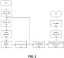
- FIG.3 shows a flowchart of the method, apparatus (system) and computer program product according to the invention. It will be understood that each block of the flowchart and combinations of blocks in the flowchart, can be implemented by computer program instructions.
- These computer program instructions may be provided to a processor of a general-purpose computer, special purpose computer, or other programmable data processing apparatus, such that the instructions, executed via the processor of the computer or other programmable data processing apparatus, create means for implementing the functions/acts specified in the flowchart.
- the general idea of the invention is to allow users of a digital camera to take not only a single photo, as in traditional camera mode, but continuously capture consecutive frames for as long as required by the user in order to acquire enough information for further processing.
- user of a digital camera may slightly change position while taking different frames, obtaining different angles of the image.
- the invention is based on the assumption that when obtaining different frames from different angles, on different frames different parts of the object of interest will be hidden by the object or objects to be removed, allowing deletion of the unwanted objects and creation of unobstructed image of the object of interest by combining elements from different frames.
- each photograph is treated as it would be divided into two planes, the first plane comprising object to be removed and the second comprising the rest of the scene, object of interest included.
- the distance between the camera and the object to be removed is relatively small.
- the distance between the object to be removed and the object of interest is bigger than the distance between the camera and the object to be removed, and therefore we can treat the second plane as planar.
- the captured data is processed online to detect people and/or objects using deep neural networks and to divide the photo into planes, wherein said people and/or objects to be removed are assigned to the first plane and the second plane comprises elements to be outputted in a final photo. This information allows to remove unwanted people and/or unmoving objects from the reference photo.
- Fig. 1 shows in general what is the purpose and what are the results of the method of automatic object removal from a photo. It can be observed that an input image contained a fence obscuring the building that was the object of interest.
- the output image received at the end of the method according to the invention contains only said building while the fence is replaced by background (the second plane elements that were behind the fence and occluded by it on the left picture of the Fig. 1 ) of good quality.
- the proposed method for automatic object removal from a photo is composed of several steps.
- the method comprises of step 100 of providing multiple photos; image alignment step 200 performed in the alignment module; object detection step 300 performed in the object detection module; the division step 400 performed in the background modeling module; tile cost function calculation step 500 performed in the calculation module; global cost optimization step 600 performed in the optimization module; blending step 700 performed in blending module and final result step 800. All the steps will be described in greater detail below.
- the method begins by step 100 of providing multiple photos. This step 100 includes two substeps.
- the first substep 101 is a substep 101 of providing 'a reference photo' by means of a camera.
- the 'reference photo' is a first photo from a series of photos taken continuously by the user of the camera.
- the reference photo is the one from which the at least one unmoving object will be removed and replaced by a background obtained from another, consecutive photo.
- the method according to the invention requires multiple photos to be taken.
- a set of images is taken in a sequence by the user of the camera from slightly different positions and therefore angles during a predetermined period in substep 102, providing at least one consecutive photo.
- This set or series of images can comprise images registered by a standalone digital camera or a digital camera embedded into another digital device like a mobile phone. The images can be written into a separate memory before processing or can be captured directly from the camera.
- the substep102 of providing at least one consecutive input image includes preferably capturing consecutive photos and their parameters directly from the camera in on the fly mode.
- the reference photo and at least one consecutive photo can be provided by reading it from a memory, acquiring image parameters, in particular its size and resolution, and optionally displaying it on a display for user perception.
- the method if the method is performed on the fly, it is the user who decides when to stop acquiring consecutive photos. In practice the period of acquisition can last from 5 to 20 seconds. In another embodiment the decision how many consecutive images should be processed is taken automatically based on the amount of acquired information, namely the method stops automatically if the required amount of information has been gathered for removal off all detected objects.
- next step of the method of automated object removal from a photo is an image alignment step 200 performed in the alignment module.
- each incoming image is aligned onto the reference frame of the first image, namely the reference photo, by use of the key points and ORB key points detector, described in more detail below.
- a 'reference frame' means here an initial position of the reference photo.
- the image alignment step 200 comprises a matching substep 202.
- each input image from a set of consecutive images is matched using for example RANSAC algorithm as described in M. A. Fischler, R. C. Bolles. Random Sample Consensus: A Paradigm for Model Fitting with Applications to Image Analysis and Automated Cartography. Comm. of the ACM, 1981 .Knowing position of those key points in each consecutive input image, each incoming image can be warped into the reference frame of the first image and then, such aligned image can be used in further processing.
- By performing this alignment step 200 it is guaranteed that the content of each incoming input image can be objectively compared with the reference photo, namely the first image. This is required since the user is moving in time between taking of two consecutive images and the same object is captured with different coordinates on each photo. It will be obvious for the person skilled in the art that the alignment step 200 will cause cutting some parts of the consecutive images for further processing.
- Each of the frames fed into the alignment module during the image alignment step 200 has its' position adjusted to previously collected frames. Namely the first image from the set of images is adjusted to the reference image, the second image is adjusted to the first image and so on. It is done by matching detected by the ORB key point detector key points of the image-to-be-aligned against key points found on reference frame (frame of the previous image) using GMS matcher. The key points detected must be distinctive and numerous enough as to allow at least robust matches, so finding holography between the frames is possible.
- Step 300 An Efficient Det architecture based neural network is used for object detection on the reference photo and each consecutive photo to produce object mask with the same resolution as reference photo.
- the object to be removed is a fence and the produced mask is a fence mask.
- This fence is detected on the reference photo and each consecutive photo.
- other types of objects such as tree branches, can be detected.
- the reference image and other consecutives photo are processed so as to detect objects, in particular parts of the fence.
- a regular rectangular regions of the photo are outputted by the object detection algorithm implemented with the above-mentioned neural network.
- the data set comprises photos with labeled parts of the fence.
- the model can be trained for other type of objects based also on a labeled data set.
- a detected region is called 'a region of interest'. All captured images and detected regions of interest are temporarily registered.
- the information which parts of a photo contains detected object is contained in a specific data structure and later on assigned to each corresponding image subregion extracted in the next step of the method according to the invention.
- the detected object to be removed is assigned to the first plane while the elements to be outputted in the final photo, that are not to be removed, are assigned to the second plane.
- both the aligned image and the object mask, for example the fence mask are forwarded to the background reconstruction module, in order to reconstruct the parts of the background from the reference image that are occluded by the fence.
- the size of a tile in 2D will results from a predetermined number of meshes into which an image should be split in 2D, while said number of tiles depends on the computation power of the hardware and can be adaptive.
- the decision how to partition a photo into tiles can be taken automatically, for example based on hardware capacity of a specific mobile phone type.
- the size and number of tiles is predetermined.
- Each photo is divided into at least 2 ⁇ 2 tiles. For example, photos are partitioned into 21 ⁇ 11 tiles. In the case of photos having 1920 ⁇ 1080 and being partitioned into 21 ⁇ 11 tiles resolution the size of a tile is (1920/21) ⁇ (1080/11).
- Each tile of the partitioned image has adjacent tiles, also called neighboring tiles or neighbors. The particulars of the relation between the tiles will be described in more detail further in the description.
- Each photo is partitioned using the same net and contains a predetermined number of rectangular subregions, namely each photo is divided into exactly the same number of tiles.
- the person skilled in the art will understand that smaller the size of a tile is the more detailed processing is possible. For example, more detailed processing is desired if the fence has a denser mesh or comprises more bars close together.
- the processing cannot be time-consuming, and preferably it is done in real time and thus the number of tiles can be determined dynamically in each case separately.
- the step 400 of dividing each photo into tiles results in a photo consisting of regular rectangle puzzles.
- Tiles of the same sizes and of the same coordinates are present on the reference photo and other consecutives photos.
- Tiles from the consecutives photos are called candidate tiles.
- each candidate tile can replace a tile of the same coordinates on the reference photo.
- only chosen tiles from the reference photo should be replaced by a candidate tile from one of consecutives photos, namely those comprising parts of the object to be removed.
- each tile is assigned an information about presence of a detected object within its area.
- the output information from the trained neural network model which is further kept in a tile can be used also in checking whether the acquisition of photos can be early stopped. Namely, if for each tile in the reference photo, for which an object to be removed has been detected, there is at least one candidate tile in at least one consecutive photo which does not contain said detected object, then it means that enough information has been acquired for processing.
- an information about the presence or a lack of detected object within its area is assigned to each tile. This will allow further to provide the answer for the question which tile should be replaced, and whether it should be replaced at all, in further steps of the method.
- the method according to the invention proceeds to a tile cost function calculation step 500 wherein the cost function for each tile from the second plane is calculated.
- Each of tiles of each image is considered as a separate node of the Markov Random Filed (MRF).
- MRF Markov Random Filed
- this step results in receiving a set of specific values C x p for each tile of the second plane, each value representing matching degree of the tile into a specific position of the reference photo. Such set of values is also calculated for tiles in the reference photo.
- the equation defines cost of assigning candidate tile x p to position p.
- the cost comprises of:
- the Applicant found that in on the fly mode processing of one incoming photo (including steps 100, 200,300,400,500) takes about 500 ms, which allows for real-time calculation and is satisfactory for commercial use.
- Next step of the method according to the invention is a step 600 of global cost optimization which enables choosing optimal tiles combination forming a new image from selected tiles chosen from tiles from all captured images.
- this step is iterative and enables choosing a combination of tiles which give the smallest possible cost.
- By iteratively optimizing the global cost function a decision for each tile in the reference photo is taken whether it should be replaced by one of tiles having the same coordinates from one of the consecutive photos.
- any algorithm that is typically used for optimizing MRFs e.g., Loopy Belief Propagation can be utilized.
- the choice of the algorithm determines the trade-of between the computation speed and possibility of convergence to the optimal configuration.
- the following greedy optimization algorithm can be used.
- the calculation is initialized with tiles taken from the reference frame (of the reference photo). Then each tile is checked by iterating at random order. During said checking, all available versions of a specific tile (namely all other tiles having the same coordinates within the net) are compared with the tile from the reference photo and their costs are calculated. The tile, with the lower cost replaces the tile with the higher cost. After replacement, the neighborhood of the replaced tile is recomputed. It means that new values of the cost function of all four neighboring tiles of the tile already replaced are calculated.
- the global cost function value for all tiles from the reference photo is known.
- single cost function value is known for each candidate tile having a position which corresponds to a considered tile in the reference image.
- theoretically all single tiles from the reference photo are virtually replaced by a corresponding candidate tile from each of consecutive photo. This process is random in terms of the tile position in the reference photo for which the calculation is performed.
- said one iteration ends if a replacing tile for which the global cost function value is lower is found. Then another iteration starts and early stopping of the optimization step is not possible until the tile with lowest value of the global cost function is found.
- the optimization algorithm stops if the predetermined number of iterations has been performed or there are no more tiles in the reference photo for which the replacement would result in receiving a lower value of the global cost function (no more replacements takes place).
- restarting of the algorithm multiple times with random initialization can be considered.
- the number of restarts should scale with the number of computations that can be performed according to the specification of the final device in which the method will be implemented.
- step 700 of blending This step is performed in order to output a final photo having at least one object removed and replaced by a background.
- a region (tile) to be reconstructed is calculated in a specific iteration of the optimization step, it is blended into the reference photo, for example if on the fly displaying is required.
- blending is performed after the end of the optimization step. Blending can be done by any suitable algorithm, for example using Poisson blending as described in [4] Patrick Perez, Michel Gangnet, Andrew Blake, "Poisson Image Editing" 2014 .
- the purpose of this step is to receive a photo of very good quality.
- the Poisson blending algorithm elevates color differences and reduces number of artifacts.
- the regions (tiles) are blended onto the reference image to remove crowd and unwanted objects and produce final result.
- the processing system (not shown) comprises a memory and a processor which is configured (by comprising several software modules) to implement steps of the method as described above.
- the processing system is embedded into a mobile phone.
- the mobile phone according to the invention comprises display means (not shown) for displaying the output of the software modules. From the user perspective the processing system allows him to perform actions as follows:
- the processing system can comprise a module for supporting steady holding of the camera. Said module outputs information on the position of the camera to be displayed by the displaying means. It increases chances of acquisition of non-blurred photos of the same quality.
- display means are configured to show a reference photo with frames surrounding detected objects and a camera position indicator. The user can see when enough information has been acquired to remove a specific object, for example based on the frame color.
- the method stops automatically if the required amount of information has been gathered for removal off all detected objects to be removed.
- aspects of the present invention can be realized by a computer of a system or apparatus (or devices such as a CPU or MPU) that reads out and executes a computer program product recorded on a memory device to perform the functions of the above-described embodiment(s), and by a method, the steps of which are performed by a computer of a system or apparatus by, for example, reading out and executing a program recorded on a memory device to perform the functions of the above-described embodiment(s).
- the claimed computer program product is provided to the computer for example via a network or from a recording medium of various types serving as the memory device.
- the computer program product according to the invention comprises also a non-transitory machine-readable medium.
Landscapes
- Physics & Mathematics (AREA)
- General Physics & Mathematics (AREA)
- Engineering & Computer Science (AREA)
- Theoretical Computer Science (AREA)
- Image Processing (AREA)
Applications Claiming Priority (1)
| Application Number | Priority Date | Filing Date | Title |
|---|---|---|---|
| PCT/PL2021/050038 WO2022260544A1 (en) | 2021-06-07 | 2021-06-07 | Method for automatic object removal from a photo, processing system and associated computer program product |
Publications (2)
| Publication Number | Publication Date |
|---|---|
| EP4352687A1 EP4352687A1 (en) | 2024-04-17 |
| EP4352687B1 true EP4352687B1 (en) | 2025-04-09 |
Family
ID=76943073
Family Applications (1)
| Application Number | Title | Priority Date | Filing Date |
|---|---|---|---|
| EP21742546.1A Active EP4352687B1 (en) | 2021-06-07 | 2021-06-07 | Method for automatic object removal from a photo, processing system and associated computer program product |
Country Status (4)
| Country | Link |
|---|---|
| EP (1) | EP4352687B1 (pl) |
| CN (1) | CN117441183B (pl) |
| PL (1) | PL4352687T3 (pl) |
| WO (1) | WO2022260544A1 (pl) |
Family Cites Families (8)
| Publication number | Priority date | Publication date | Assignee | Title |
|---|---|---|---|---|
| CN101266685A (zh) * | 2007-03-14 | 2008-09-17 | 中国科学院自动化研究所 | 一种基于多幅照片去除无关图像的方法 |
| KR101582478B1 (ko) * | 2012-05-03 | 2016-01-19 | 에스케이 텔레콤주식회사 | 정지영상에 포함된 헤이즈 제거를 위한 영상 처리 장치 및 그 방법 |
| CN104735364A (zh) * | 2013-12-19 | 2015-06-24 | 中兴通讯股份有限公司 | 一种照片拍摄处理方法和设备 |
| US10412316B2 (en) * | 2016-06-09 | 2019-09-10 | Google Llc | Taking photos through visual obstructions |
| CN106506981B (zh) * | 2016-11-25 | 2019-04-19 | 阿依瓦(北京)技术有限公司 | 生成高动态范围图像的设备和方法 |
| US10586308B2 (en) * | 2017-05-09 | 2020-03-10 | Adobe Inc. | Digital media environment for removal of obstructions in a digital image scene |
| US11057576B2 (en) * | 2019-02-15 | 2021-07-06 | Shutterfly, Llc | System and method for automated detection and replacement of photographic scenes |
| WO2021035228A2 (en) * | 2020-12-03 | 2021-02-25 | Futurewei Technologies, Inc. | System and methods for photo in-painting of unwanted objects with auxiliary photos on smartphone |
-
2021
- 2021-06-07 PL PL21742546.1T patent/PL4352687T3/pl unknown
- 2021-06-07 EP EP21742546.1A patent/EP4352687B1/en active Active
- 2021-06-07 WO PCT/PL2021/050038 patent/WO2022260544A1/en not_active Ceased
- 2021-06-07 CN CN202180099061.6A patent/CN117441183B/zh active Active
Also Published As
| Publication number | Publication date |
|---|---|
| EP4352687A1 (en) | 2024-04-17 |
| CN117441183B (zh) | 2026-06-02 |
| CN117441183A (zh) | 2024-01-23 |
| PL4352687T3 (pl) | 2025-06-30 |
| WO2022260544A1 (en) | 2022-12-15 |
Similar Documents
| Publication | Publication Date | Title |
|---|---|---|
| JP6553285B2 (ja) | シーン再構成方法、装置、端末機器及び記憶媒体 | |
| EP2087466B1 (en) | Generation of depth map for an image | |
| CN111401205B (zh) | 动作识别方法及装置、电子设备、计算机可读存储介质 | |
| KR102135770B1 (ko) | 스테레오 카메라 기반의 3차원 얼굴 복원 방법 및 장치 | |
| EP3048579B1 (en) | Structure analysis method for recovering missing structures in an image after object removal | |
| KR20150104073A (ko) | 2d 이미지 시퀀스들로부터 3d 장면을 재구성하기 위한 방법 | |
| CN110163265A (zh) | 数据处理方法、装置及计算机设备 | |
| JP4911191B2 (ja) | 画像処理装置および画像処理プログラム | |
| WO2017173578A1 (zh) | 一种图像增强方法及装置 | |
| CN113222845A (zh) | 基于卷积神经网络的肖像外部阴影去除方法 | |
| CN113327316B (zh) | 一种图像处理方法、装置、设备及存储介质 | |
| CN112991159A (zh) | 人脸光照质量评估方法、系统、服务器与计算机可读介质 | |
| CN105488771B (zh) | 光场图像编辑方法及装置 | |
| US20150317520A1 (en) | Method and apparatus for extraction of static scene photo from sequence of images | |
| CN110717980A (zh) | 区域三维重建方法、装置及计算机可读存储介质 | |
| CN115115538B (zh) | 视频处理方法、装置、设备及存储介质 | |
| US20210065336A1 (en) | Method for generating a reduced-blur digital image | |
| CN118608699A (zh) | 三维建模方法及计算机装置 | |
| CN112651357B (zh) | 图像中目标物体的分割方法、三维重建方法及相关装置 | |
| CN116468736B (zh) | 基于空间结构的前景图像分割方法、装置、设备、介质 | |
| US20230209182A1 (en) | Automatic photography composition recommendation | |
| CN116051980B (zh) | 基于倾斜摄影的建筑识别方法、系统、电子设备及介质 | |
| KR101913623B1 (ko) | 촬영 이미지를 이용한 3차원 광고 생성 방법 | |
| CN113256484B (zh) | 一种对图像进行风格化处理的方法及装置 | |
| WO2022260544A1 (en) | Method for automatic object removal from a photo, processing system and associated computer program product |
Legal Events
| Date | Code | Title | Description |
|---|---|---|---|
| STAA | Information on the status of an ep patent application or granted ep patent |
Free format text: STATUS: UNKNOWN |
|
| STAA | Information on the status of an ep patent application or granted ep patent |
Free format text: STATUS: THE INTERNATIONAL PUBLICATION HAS BEEN MADE |
|
| PUAI | Public reference made under article 153(3) epc to a published international application that has entered the european phase |
Free format text: ORIGINAL CODE: 0009012 |
|
| STAA | Information on the status of an ep patent application or granted ep patent |
Free format text: STATUS: REQUEST FOR EXAMINATION WAS MADE |
|
| 17P | Request for examination filed |
Effective date: 20231124 |
|
| AK | Designated contracting states |
Kind code of ref document: A1 Designated state(s): AL AT BE BG CH CY CZ DE DK EE ES FI FR GB GR HR HU IE IS IT LI LT LU LV MC MK MT NL NO PL PT RO RS SE SI SK SM TR |
|
| DAV | Request for validation of the european patent (deleted) | ||
| DAX | Request for extension of the european patent (deleted) | ||
| REG | Reference to a national code |
Ref country code: DE Ref legal event code: R079 Free format text: PREVIOUS MAIN CLASS: G06T0005000000 Ref country code: DE Ref legal event code: R079 Ref document number: 602021028930 Country of ref document: DE Free format text: PREVIOUS MAIN CLASS: G06T0005000000 Ipc: G06T0005770000 |
|
| GRAP | Despatch of communication of intention to grant a patent |
Free format text: ORIGINAL CODE: EPIDOSNIGR1 |
|
| STAA | Information on the status of an ep patent application or granted ep patent |
Free format text: STATUS: GRANT OF PATENT IS INTENDED |
|
| RIC1 | Information provided on ipc code assigned before grant |
Ipc: G06T 5/77 20240101AFI20241018BHEP |
|
| INTG | Intention to grant announced |
Effective date: 20241030 |
|
| GRAS | Grant fee paid |
Free format text: ORIGINAL CODE: EPIDOSNIGR3 |
|
| GRAA | (expected) grant |
Free format text: ORIGINAL CODE: 0009210 |
|
| STAA | Information on the status of an ep patent application or granted ep patent |
Free format text: STATUS: THE PATENT HAS BEEN GRANTED |
|
| AK | Designated contracting states |
Kind code of ref document: B1 Designated state(s): AL AT BE BG CH CY CZ DE DK EE ES FI FR GB GR HR HU IE IS IT LI LT LU LV MC MK MT NL NO PL PT RO RS SE SI SK SM TR |
|
| REG | Reference to a national code |
Ref country code: GB Ref legal event code: FG4D |
|
| REG | Reference to a national code |
Ref country code: CH Ref legal event code: EP |
|
| REG | Reference to a national code |
Ref country code: DE Ref legal event code: R096 Ref document number: 602021028930 Country of ref document: DE |
|
| REG | Reference to a national code |
Ref country code: IE Ref legal event code: FG4D |
|
| PGFP | Annual fee paid to national office [announced via postgrant information from national office to epo] |
Ref country code: AT Payment date: 20250721 Year of fee payment: 5 |
|
| REG | Reference to a national code |
Ref country code: NL Ref legal event code: MP Effective date: 20250409 |
|
| PG25 | Lapsed in a contracting state [announced via postgrant information from national office to epo] |
Ref country code: NL Free format text: LAPSE BECAUSE OF FAILURE TO SUBMIT A TRANSLATION OF THE DESCRIPTION OR TO PAY THE FEE WITHIN THE PRESCRIBED TIME-LIMIT Effective date: 20250409 |
|
| REG | Reference to a national code |
Ref country code: AT Ref legal event code: MK05 Ref document number: 1784223 Country of ref document: AT Kind code of ref document: T Effective date: 20250409 |
|
| PG25 | Lapsed in a contracting state [announced via postgrant information from national office to epo] |
Ref country code: PT Free format text: LAPSE BECAUSE OF FAILURE TO SUBMIT A TRANSLATION OF THE DESCRIPTION OR TO PAY THE FEE WITHIN THE PRESCRIBED TIME-LIMIT Effective date: 20250811 Ref country code: FI Free format text: LAPSE BECAUSE OF FAILURE TO SUBMIT A TRANSLATION OF THE DESCRIPTION OR TO PAY THE FEE WITHIN THE PRESCRIBED TIME-LIMIT Effective date: 20250409 Ref country code: ES Free format text: LAPSE BECAUSE OF FAILURE TO SUBMIT A TRANSLATION OF THE DESCRIPTION OR TO PAY THE FEE WITHIN THE PRESCRIBED TIME-LIMIT Effective date: 20250409 |
|
| REG | Reference to a national code |
Ref country code: LT Ref legal event code: MG9D |
|
| PG25 | Lapsed in a contracting state [announced via postgrant information from national office to epo] |
Ref country code: GR Free format text: LAPSE BECAUSE OF FAILURE TO SUBMIT A TRANSLATION OF THE DESCRIPTION OR TO PAY THE FEE WITHIN THE PRESCRIBED TIME-LIMIT Effective date: 20250710 Ref country code: NO Free format text: LAPSE BECAUSE OF FAILURE TO SUBMIT A TRANSLATION OF THE DESCRIPTION OR TO PAY THE FEE WITHIN THE PRESCRIBED TIME-LIMIT Effective date: 20250709 |
|
| PG25 | Lapsed in a contracting state [announced via postgrant information from national office to epo] |
Ref country code: BG Free format text: LAPSE BECAUSE OF FAILURE TO SUBMIT A TRANSLATION OF THE DESCRIPTION OR TO PAY THE FEE WITHIN THE PRESCRIBED TIME-LIMIT Effective date: 20250409 |
|
| PG25 | Lapsed in a contracting state [announced via postgrant information from national office to epo] |
Ref country code: HR Free format text: LAPSE BECAUSE OF FAILURE TO SUBMIT A TRANSLATION OF THE DESCRIPTION OR TO PAY THE FEE WITHIN THE PRESCRIBED TIME-LIMIT Effective date: 20250409 |
|
| PG25 | Lapsed in a contracting state [announced via postgrant information from national office to epo] |
Ref country code: AT Free format text: LAPSE BECAUSE OF FAILURE TO SUBMIT A TRANSLATION OF THE DESCRIPTION OR TO PAY THE FEE WITHIN THE PRESCRIBED TIME-LIMIT Effective date: 20250409 |
|
| PG25 | Lapsed in a contracting state [announced via postgrant information from national office to epo] |
Ref country code: RS Free format text: LAPSE BECAUSE OF FAILURE TO SUBMIT A TRANSLATION OF THE DESCRIPTION OR TO PAY THE FEE WITHIN THE PRESCRIBED TIME-LIMIT Effective date: 20250709 |
|
| PG25 | Lapsed in a contracting state [announced via postgrant information from national office to epo] |
Ref country code: IS Free format text: LAPSE BECAUSE OF FAILURE TO SUBMIT A TRANSLATION OF THE DESCRIPTION OR TO PAY THE FEE WITHIN THE PRESCRIBED TIME-LIMIT Effective date: 20250809 |
|
| PG25 | Lapsed in a contracting state [announced via postgrant information from national office to epo] |
Ref country code: LV Free format text: LAPSE BECAUSE OF FAILURE TO SUBMIT A TRANSLATION OF THE DESCRIPTION OR TO PAY THE FEE WITHIN THE PRESCRIBED TIME-LIMIT Effective date: 20250409 |
|
| REG | Reference to a national code |
Ref country code: DE Ref legal event code: R097 Ref document number: 602021028930 Country of ref document: DE |
|
| PG25 | Lapsed in a contracting state [announced via postgrant information from national office to epo] |
Ref country code: DK Free format text: LAPSE BECAUSE OF FAILURE TO SUBMIT A TRANSLATION OF THE DESCRIPTION OR TO PAY THE FEE WITHIN THE PRESCRIBED TIME-LIMIT Effective date: 20250409 Ref country code: SM Free format text: LAPSE BECAUSE OF FAILURE TO SUBMIT A TRANSLATION OF THE DESCRIPTION OR TO PAY THE FEE WITHIN THE PRESCRIBED TIME-LIMIT Effective date: 20250409 |
|
| PG25 | Lapsed in a contracting state [announced via postgrant information from national office to epo] |
Ref country code: CZ Free format text: LAPSE BECAUSE OF FAILURE TO SUBMIT A TRANSLATION OF THE DESCRIPTION OR TO PAY THE FEE WITHIN THE PRESCRIBED TIME-LIMIT Effective date: 20250409 |
|
| PG25 | Lapsed in a contracting state [announced via postgrant information from national office to epo] |
Ref country code: EE Free format text: LAPSE BECAUSE OF FAILURE TO SUBMIT A TRANSLATION OF THE DESCRIPTION OR TO PAY THE FEE WITHIN THE PRESCRIBED TIME-LIMIT Effective date: 20250409 |
|
| PG25 | Lapsed in a contracting state [announced via postgrant information from national office to epo] |
Ref country code: SK Free format text: LAPSE BECAUSE OF FAILURE TO SUBMIT A TRANSLATION OF THE DESCRIPTION OR TO PAY THE FEE WITHIN THE PRESCRIBED TIME-LIMIT Effective date: 20250409 |
|
| REG | Reference to a national code |
Ref country code: CH Ref legal event code: H13 Free format text: ST27 STATUS EVENT CODE: U-0-0-H10-H13 (AS PROVIDED BY THE NATIONAL OFFICE) Effective date: 20260127 |
|
| PG25 | Lapsed in a contracting state [announced via postgrant information from national office to epo] |
Ref country code: IT Free format text: LAPSE BECAUSE OF FAILURE TO SUBMIT A TRANSLATION OF THE DESCRIPTION OR TO PAY THE FEE WITHIN THE PRESCRIBED TIME-LIMIT Effective date: 20250409 |
|
| PG25 | Lapsed in a contracting state [announced via postgrant information from national office to epo] |
Ref country code: MC Free format text: LAPSE BECAUSE OF FAILURE TO SUBMIT A TRANSLATION OF THE DESCRIPTION OR TO PAY THE FEE WITHIN THE PRESCRIBED TIME-LIMIT Effective date: 20250409 |
|
| PLBE | No opposition filed within time limit |
Free format text: ORIGINAL CODE: 0009261 |
|
| STAA | Information on the status of an ep patent application or granted ep patent |
Free format text: STATUS: NO OPPOSITION FILED WITHIN TIME LIMIT |
|
| PG25 | Lapsed in a contracting state [announced via postgrant information from national office to epo] |
Ref country code: LU Free format text: LAPSE BECAUSE OF NON-PAYMENT OF DUE FEES Effective date: 20250607 |
|
| REG | Reference to a national code |
Ref country code: CH Ref legal event code: L10 Free format text: ST27 STATUS EVENT CODE: U-0-0-L10-L00 (AS PROVIDED BY THE NATIONAL OFFICE) Effective date: 20260218 |
|
| REG | Reference to a national code |
Ref country code: BE Ref legal event code: MM Effective date: 20250630 |
|
| PG25 | Lapsed in a contracting state [announced via postgrant information from national office to epo] |
Ref country code: RO Free format text: LAPSE BECAUSE OF FAILURE TO SUBMIT A TRANSLATION OF THE DESCRIPTION OR TO PAY THE FEE WITHIN THE PRESCRIBED TIME-LIMIT Effective date: 20250409 |
|
| 26N | No opposition filed |
Effective date: 20260112 |
|
| GBPC | Gb: european patent ceased through non-payment of renewal fee |
Effective date: 20250709 |
|
| PG25 | Lapsed in a contracting state [announced via postgrant information from national office to epo] |
Ref country code: GB Free format text: LAPSE BECAUSE OF NON-PAYMENT OF DUE FEES Effective date: 20250709 |
|
| PG25 | Lapsed in a contracting state [announced via postgrant information from national office to epo] |
Ref country code: IE Free format text: LAPSE BECAUSE OF NON-PAYMENT OF DUE FEES Effective date: 20250607 |
|
| PG25 | Lapsed in a contracting state [announced via postgrant information from national office to epo] |
Ref country code: BE Free format text: LAPSE BECAUSE OF NON-PAYMENT OF DUE FEES Effective date: 20250630 |
|
| PG25 | Lapsed in a contracting state [announced via postgrant information from national office to epo] |
Ref country code: FR Free format text: LAPSE BECAUSE OF NON-PAYMENT OF DUE FEES Effective date: 20250609 |
|
| PG25 | Lapsed in a contracting state [announced via postgrant information from national office to epo] |
Ref country code: CH Free format text: LAPSE BECAUSE OF NON-PAYMENT OF DUE FEES Effective date: 20250630 |
|
| PG25 | Lapsed in a contracting state [announced via postgrant information from national office to epo] |
Ref country code: LT Free format text: LAPSE BECAUSE OF FAILURE TO SUBMIT A TRANSLATION OF THE DESCRIPTION OR TO PAY THE FEE WITHIN THE PRESCRIBED TIME-LIMIT Effective date: 20250409 |
|
| PGFP | Annual fee paid to national office [announced via postgrant information from national office to epo] |
Ref country code: PL Payment date: 20260528 Year of fee payment: 6 |
|
| PGFP | Annual fee paid to national office [announced via postgrant information from national office to epo] |
Ref country code: DE Payment date: 20260622 Year of fee payment: 6 |
|
| PG25 | Lapsed in a contracting state [announced via postgrant information from national office to epo] |
Ref country code: SE Free format text: LAPSE BECAUSE OF FAILURE TO SUBMIT A TRANSLATION OF THE DESCRIPTION OR TO PAY THE FEE WITHIN THE PRESCRIBED TIME-LIMIT Effective date: 20250409 Ref country code: CY Free format text: LAPSE BECAUSE OF FAILURE TO SUBMIT A TRANSLATION OF THE DESCRIPTION OR TO PAY THE FEE WITHIN THE PRESCRIBED TIME-LIMIT Effective date: 20250409 |