EP4352376B1 - Automatisierte entkopplungsstossisolierung für vibrationskoppler - Google Patents
Automatisierte entkopplungsstossisolierung für vibrationskoppler Download PDFInfo
- Publication number
- EP4352376B1 EP4352376B1 EP22724308.6A EP22724308A EP4352376B1 EP 4352376 B1 EP4352376 B1 EP 4352376B1 EP 22724308 A EP22724308 A EP 22724308A EP 4352376 B1 EP4352376 B1 EP 4352376B1
- Authority
- EP
- European Patent Office
- Prior art keywords
- compressive fit
- bushing
- fit rod
- shock
- compressive
- Prior art date
- Legal status (The legal status is an assumption and is not a legal conclusion. Google has not performed a legal analysis and makes no representation as to the accuracy of the status listed.)
- Active
Links
Images



Classifications
-
- F—MECHANICAL ENGINEERING; LIGHTING; HEATING; WEAPONS; BLASTING
- F16—ENGINEERING ELEMENTS AND UNITS; GENERAL MEASURES FOR PRODUCING AND MAINTAINING EFFECTIVE FUNCTIONING OF MACHINES OR INSTALLATIONS; THERMAL INSULATION IN GENERAL
- F16F—SPRINGS; SHOCK-ABSORBERS; MEANS FOR DAMPING VIBRATION
- F16F15/00—Suppression of vibrations in systems; Means or arrangements for avoiding or reducing out-of-balance forces, e.g. due to motion
- F16F15/02—Suppression of vibrations of non-rotating, e.g. reciprocating systems; Suppression of vibrations of rotating systems by use of members not moving with the rotating systems
-
- F—MECHANICAL ENGINEERING; LIGHTING; HEATING; WEAPONS; BLASTING
- F16—ENGINEERING ELEMENTS AND UNITS; GENERAL MEASURES FOR PRODUCING AND MAINTAINING EFFECTIVE FUNCTIONING OF MACHINES OR INSTALLATIONS; THERMAL INSULATION IN GENERAL
- F16F—SPRINGS; SHOCK-ABSORBERS; MEANS FOR DAMPING VIBRATION
- F16F1/00—Springs
- F16F1/36—Springs made of rubber or other material having high internal friction, e.g. thermoplastic elastomers
- F16F1/373—Springs made of rubber or other material having high internal friction, e.g. thermoplastic elastomers characterised by having a particular shape
- F16F1/3732—Springs made of rubber or other material having high internal friction, e.g. thermoplastic elastomers characterised by having a particular shape having an annular or the like shape, e.g. grommet-type resilient mountings
- F16F1/3735—Multi-part grommet-type resilient mountings
-
- F—MECHANICAL ENGINEERING; LIGHTING; HEATING; WEAPONS; BLASTING
- F16—ENGINEERING ELEMENTS AND UNITS; GENERAL MEASURES FOR PRODUCING AND MAINTAINING EFFECTIVE FUNCTIONING OF MACHINES OR INSTALLATIONS; THERMAL INSULATION IN GENERAL
- F16F—SPRINGS; SHOCK-ABSORBERS; MEANS FOR DAMPING VIBRATION
- F16F1/00—Springs
- F16F1/36—Springs made of rubber or other material having high internal friction, e.g. thermoplastic elastomers
- F16F1/38—Springs made of rubber or other material having high internal friction, e.g. thermoplastic elastomers with a sleeve of elastic material between a rigid outer sleeve and a rigid inner sleeve or pin, i.e. bushing-type
-
- G—PHYSICS
- G01—MEASURING; TESTING
- G01M—TESTING STATIC OR DYNAMIC BALANCE OF MACHINES OR STRUCTURES; TESTING OF STRUCTURES OR APPARATUS, NOT OTHERWISE PROVIDED FOR
- G01M7/00—Vibration-testing of structures; Shock-testing of structures
- G01M7/02—Vibration-testing by means of a shake table
-
- G—PHYSICS
- G01—MEASURING; TESTING
- G01M—TESTING STATIC OR DYNAMIC BALANCE OF MACHINES OR STRUCTURES; TESTING OF STRUCTURES OR APPARATUS, NOT OTHERWISE PROVIDED FOR
- G01M7/00—Vibration-testing of structures; Shock-testing of structures
- G01M7/02—Vibration-testing by means of a shake table
- G01M7/027—Specimen mounting arrangements, e.g. table head adapters
-
- F—MECHANICAL ENGINEERING; LIGHTING; HEATING; WEAPONS; BLASTING
- F16—ENGINEERING ELEMENTS AND UNITS; GENERAL MEASURES FOR PRODUCING AND MAINTAINING EFFECTIVE FUNCTIONING OF MACHINES OR INSTALLATIONS; THERMAL INSULATION IN GENERAL
- F16F—SPRINGS; SHOCK-ABSORBERS; MEANS FOR DAMPING VIBRATION
- F16F2224/00—Materials; Material properties
- F16F2224/02—Materials; Material properties solids
- F16F2224/025—Elastomers
-
- F—MECHANICAL ENGINEERING; LIGHTING; HEATING; WEAPONS; BLASTING
- F16—ENGINEERING ELEMENTS AND UNITS; GENERAL MEASURES FOR PRODUCING AND MAINTAINING EFFECTIVE FUNCTIONING OF MACHINES OR INSTALLATIONS; THERMAL INSULATION IN GENERAL
- F16F—SPRINGS; SHOCK-ABSORBERS; MEANS FOR DAMPING VIBRATION
- F16F2226/00—Manufacturing; Treatments
- F16F2226/04—Assembly or fixing methods; methods to form or fashion parts
- F16F2226/045—Press-fitting
-
- F—MECHANICAL ENGINEERING; LIGHTING; HEATING; WEAPONS; BLASTING
- F16—ENGINEERING ELEMENTS AND UNITS; GENERAL MEASURES FOR PRODUCING AND MAINTAINING EFFECTIVE FUNCTIONING OF MACHINES OR INSTALLATIONS; THERMAL INSULATION IN GENERAL
- F16F—SPRINGS; SHOCK-ABSORBERS; MEANS FOR DAMPING VIBRATION
- F16F2228/00—Functional characteristics, e.g. variability, frequency-dependence
- F16F2228/06—Stiffness
- F16F2228/066—Variable stiffness
-
- F—MECHANICAL ENGINEERING; LIGHTING; HEATING; WEAPONS; BLASTING
- F16—ENGINEERING ELEMENTS AND UNITS; GENERAL MEASURES FOR PRODUCING AND MAINTAINING EFFECTIVE FUNCTIONING OF MACHINES OR INSTALLATIONS; THERMAL INSULATION IN GENERAL
- F16F—SPRINGS; SHOCK-ABSORBERS; MEANS FOR DAMPING VIBRATION
- F16F2230/00—Purpose; Design features
- F16F2230/0005—Attachment, e.g. to facilitate mounting onto confer adjustability
-
- F—MECHANICAL ENGINEERING; LIGHTING; HEATING; WEAPONS; BLASTING
- F16—ENGINEERING ELEMENTS AND UNITS; GENERAL MEASURES FOR PRODUCING AND MAINTAINING EFFECTIVE FUNCTIONING OF MACHINES OR INSTALLATIONS; THERMAL INSULATION IN GENERAL
- F16F—SPRINGS; SHOCK-ABSORBERS; MEANS FOR DAMPING VIBRATION
- F16F2236/00—Mode of stressing of basic spring or damper elements or devices incorporating such elements
- F16F2236/04—Compression
Definitions
- the disclosure relates to a shock isolator arranged between automated coupler parts in a vibration testing unit.
- vibration testing for components that will be subject to vibrations during normal operation.
- hardware, circuit card assemblies including stacks of circuit cards, and other subsystem level units may be subject to random vibrations, harmonic vibrations, and controlled shock profiles when implemented in a particular environment.
- exemplary environments in which the components may be subject to vibrations include moving platforms such as aircrafts, missiles, spacecrafts or satellites, sea vessels, land vehicles, etc.
- Vibration testing may include automated coupling and decoupling of components with a vibration testing unit utilizing a conventional coupler which includes an upper coupler part and a lower coupler part. After the vibration testing, the parts are disengaged and decoupled from the vibration testing unit, but the environment imparted on the parts during the decoupling may not be benign.
- the pressure applied to decouple the upper and lower coupler parts may cause the upper coupler part to rapidly accelerate upwardly and then downwardly relative to the lower coupler part such that the upper coupler part hits the lower coupler part and causes a significant shock.
- Conventional couplers may not be sufficient in preventing shock transfer between the upper and lower coupler parts during decoupling, such that the shock occurring during decoupling may exceed the shock specifications for the particular component that is subject to the vibration testing. Consequently, the test component may be damaged by the excess shock.
- US 3 074 269 A discloses an electrodynamic actuator comprising a table, a support mounting said table for approximately horizontal linear movements, means responsive to a variable current for causing said movements of said table, and means for providing a variable damping for said table including a magnet attached to and movable with said table and having its polar ends spaced apart in the direction of said linear movements, and a closed circuit having in series therein a variable resistance and a wire coil carried by said support and wound about but separate from said magnet intermediate of the ends thereof, whereby the movement of said magnet relative to said coil will exert a damping force the effectiveness of which may be varied by operation of said variable resistance.
- US 2017/045110 A1 discloses that two or more vehicle components can be operatively connected with one or more fasteners configured to provide selectively variable dampening characteristics.
- the fastener can include a dampening unit configured to provide different dampening characteristics based on a torque applied to the fastener.
- the dampening unit can provide different dampening characteristics based on an amount of compression the dampening unit is under.
- Target dampening characteristics between two or more components can be determined.
- a torque can be determined and applied to the fastener based on the target dampening characteristics. The torque can cause the dampening unit of the fastener to compress and provide the target dampening characteristics between the components.
- US 9 696 236 B1 discloses a test apparatus including a vibratory body that shakes a device under testing (DUT), a pedestal dedicated to support the DUT and disposed on the vibratory body, and a clamping mechanism operative to selectively clamp the pedestal to the vibratory body and release the pedestal from the vibratory body.
- the vibratory body and the pedestal define a cavity in which the clamping mechanism is disposed.
- the clamping mechanism includes a clamp ring and at least one locking element carried by the clamp ring so as to be displaceable in a radial direction relative to the clamp ring, at least one tang facing the at least one locking element in the radial direction, and a piston slidable in an axial direction relative to the clamp ring between a first position at which the pedestal is free from vibratory body and a second position at which the locking element is compressed between the piston and the tang.
- US 4 633 716 A discloses a structure to provide increased surface area on the head of a shaker used for vibrational testing.
- the structure includes a base plate for attachment to the head of the shaker and a larger expanded head connected thereto by a frustoconical structure surrounding a cylindrical structure surrounding a spoke structure, all designed to increase the vibrational frequency at which undesired vibratory modes appear in the surface of the expanded head which otherwise can provide nonuniform vibration loading to the items attached thereto during testing.
- the structure also includes improved means for attachment to the shaker.
- the disclosure provides a shock isolator arranged between automated coupler parts in a vibration testing unit, the shock isolator comprising: a bushing; and a compressive fit rod supported in the bushing, the compressive fit rod being compressible inside the bushing to disable the shock isolator when the automated coupler parts are engaged during vibration testing, the compressive fit rod being expandable outwardly from the bushing to activate the shock isolator and absorb excess shock energy when the automated coupler parts are disengaged.
- the disclosure provides a vibration testing unit comprising: an automated coupler having an upper coupler part and a lower coupler part that are engaged during vibration testing and disengaged after the vibration testing; and a plurality of shock isolators arranged in the lower coupler part between the upper coupler part and the lower coupler part, each of the plurality of shock isolators including a bushing and a compressive fit rod supported in the bushing, the compressive fit rod being compressible to a compressed position in which the compressive fit rod is compressed inside the bushing to disable the plurality of shock isolators when the upper coupler part and the lower coupler part are engaged during vibration testing, the compressive fit rod being expandable to an expanded position in which the compressive fit rod expands outwardly from the bushing to activate the plurality of shock isolators and absorb excess shock energy when the upper coupler part and the lower coupler part are disengaged.
- the disclosure provides a method of vibration testing, the method comprising: press-fitting a compressive fit rod into a bushing to form a shock isolator; inserting one or more shock isolators into a lower coupler part of two automated coupler parts between the lower coupler part and an upper coupler part of the two automated coupler parts; engaging the two automated coupler parts during vibration testing and disengaging the two automated coupler parts after the vibration testing; compressing an upper portion of the compressive fit rod inside the bushing to disable the one or more shock isolators during the vibration testing; and expanding the upper portion of the compressive fit rod upwardly from and outside the bushing to activate the one or more shock isolators and absorb excess shock energy when the two automated coupler parts are disengaged.
- the present application provides shock isolation for a vibration testing unit that includes an automated coupler.
- the shock isolator is arranged between two automated coupler parts. When the coupler parts are engaged and coupled during vibration testing of a component, the shock isolator is disabled due to compression. When the coupler parts are disengaged and decoupled after vibration testing, the shock isolator is expanded and can absorb excess shock energy and prevent shock transfer between the coupler parts that may damage the test component.
- Each shock isolator includes a bushing that is inserted in the lower coupler part and a compressive fit rod that is press-fit into the bushing.
- the compressive fit rod is formed of an elastomeric material that is able to be repeatedly compressed and expanded without permanent deformation.
- the bushing has a chamfered volume and the compressive fit rod has a corresponding compressible volume that is displaced into the chamfered volume to disable the shock isolator when the coupler parts are engaged. After vibration testing, the coupler parts are disengaged and the compressive fit rod expands to its decompressed shape to activate the shock isolator and absorb the excess shock energy.
- the compressive fit rod has a predetermined durometer and a lower portion of the compressive fit rod is press-fit into the bushing.
- the upper portion of the compressive fit rod is a compressive volume that is deformed during coupling.
- An axial length of the compressible volume may be less than ten percent of the total axial length of the compressive fit rod which enables the compression profile of the compressive fit rod to be linear.
- an automated coupler may include one or more shock isolators arranged between the two coupler parts.
- an automated coupler may include a shock isolator that is disabled during coupling of the two automated coupler parts and activated when the two automated coupler parts are decoupled to absorb excess shock energy.
- a shock isolator may include a bushing and a compressive fit rod inserted in the bushing.
- a shock isolator may include a bushing and a compressive fit rod that is deformable inside the bushing to disable the shock isolator when two automated coupler parts are coupled during vibration testing.
- a shock isolator may include a bushing having a chamfered volume and a compressive fit rod having a corresponding compressible volume that fits inside the chamfered volume.
- a shock isolator may include a bushing and a compressive fit rod having a compressible volume that is the only portion of the compressive fit rod deformable inside the bushing.
- a shock isolator is arranged between coupler parts in an automated coupler and includes a bushing, and a compressive fit rod supported in the bushing, the compressive fit rod being compressible inside the bushing to disable the shock isolator when the coupler parts are coupled during vibration testing, the compressive fit rod being expandable outwardly from the bushing to activate the shock isolator and absorb excess shock energy when the coupler parts are decoupled.
- the bushing may define a chamfered volume and the compressive fit rod may have a compressible volume that is equivalent to the chamfered volume, wherein the chamfered volume is filled by the compressive fit rod when the compressive fit rod is deformed during compression.
- the chamfered volume may be defined by a tapered surface that tapers radially inwardly from a radial mating surface of the bushing.
- the radial mating surface may be an upper surface of the bushing that engages an upper coupler part of the coupler parts.
- the tapered surface may extend an axial distance that is less than half of an entire axial length of the bushing.
- the tapered surface may be angled by between ten and 20 degrees relative to a longitudinal axis of the shock isolator.
- the compressive fit rod may have a compressible volume that is deformed during compression and has an axial length that is ten percent or less of a total axial length of the compressive fit rod.
- the compressible volume may be an uppermost portion of the compressive fit rod.
- the compressive fit rod may be press-fit into the bushing.
- the compressive fit rod may have a compressive fit with the bushing that is ten percent or less.
- the compressive fit rod may define an axially-extending through-aperture.
- the bushing may define a radial seat against which an axial end of the compressive fit rod is supported.
- the compressive fit rod may be formed of an elastomeric material having a durometer between 40 and 70.
- the compressive fit rod may be formed of a urethane material.
- the bushing may be formed of a thermoplastic polymer material.
- an upper portion of the compressive fit rod may be compressed inside an upper portion of the bushing when in a compressed position, and wherein the upper portion expands upwardly and outside of the bushing to an expanded position which corresponds to a decompressed or normal shape of the compressive fit rod.
- a vibration testing unit includes an upper coupler part and a lower coupler part that are coupled during vibration testing and decoupled after the vibration testing, and a plurality of shock isolators arranged in the lower coupler part between the upper coupler part and the lower coupler part, each of the plurality of shock isolators including a bushing and a compressive fit rod supported in the bushing, the compressive fit rod being compressible to a compressed position in which the compressive fit rod is compressed inside the bushing to disable the plurality of shock isolators when the upper coupler part and the lower coupler part are coupled during vibration testing, the compressive fit rod being expandable to an expanded position in which the compressive fit rod expands outwardly from the bushing to activate the plurality of shock isolators and prevent shock transfer when the upper coupler part and the lower coupler part are decoupled.
- a method of vibration testing includes press-fitting a compressive fit rod into a bushing to form a shock isolator, inserting one or more shock isolators into a lower coupler part of two automated coupler parts between the lower coupler part and an upper coupler part of the two automated coupler parts, coupling the two automated coupler parts during vibration testing and decoupling the two automated coupler parts after the vibration testing, compressing an upper portion of the compressive fit rod inside the bushing to disable the one or more shock isolators during the vibration testing, and expanding the upper portion of the compressive fit rod upwardly from and outside the bushing to activate the one or more shock isolators and prevent shock transfer when the two automated coupler parts are decoupled.
- compressing the upper portion of the compressive fit rod may include filling a chamfered volume formed in an upper portion of the bushing and expanding the upper portion of the compressive fit rod includes removing the compressive fit rod from the chamfered volume.
- compressing the upper portion of the compressive fit rod may include compressing a compressible volume of the compressive fit rod that has an axial length of the compressive fit rod that is ten percent or less of a total axial length of the compressive fit rod.
- a vibration testing unit includes two automated coupler parts that are engaged together and coupled during vibration testing of a component and decoupled after the vibration testing. Vibration testing may occur in an enclosed automated system in which there is no manual operation or human interaction.
- the vibration testing unit described herein may be used for any suitable component that is subject to vibration during normal operation. When implemented in a moving platform during normal operation, such as an aircraft, missile, spacecraft or satellite, sea vessel, land vehicle, etc., the component may be subject to random vibrations, harmonic vibrations, or controlled shock profiles depending on the environment. Exemplary components that may undergo vibration testing prior to operation include hardware components, circuit card assemblies, stacks of circuit cards, and other subsystem level units.
- the vibration testing unit 20 includes two automated coupler parts 22, 24 having an upper coupler part 22 and a lower coupler part 24 that are engageable with each other.
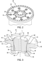
- Fig. 2 shows a top view of the lower coupler part 24 with the upper coupler part 22 removed.
- An interior area 26 is arranged along a central axis A of the vibration testing unit 20 within the vibration testing unit 20. The interior area 26 is enclosed between the two automated coupler parts 22, 24 when the vibration testing unit 20 is assembled.
- a component 28 is received and supported in the interior area 26 for automated vibration testing performed by the vibration testing unit 20.
- the interior area 26 may be shaped and sized to accommodate any suitable component. Any suitable fasteners 30 or other support mechanisms 32 may be used to support and accommodate the component 28.
- the vibration testing unit 20 may have many different configurations depending on the component or components to be tested.
- the upper coupler part 22 and the lower coupler part 24 are engaged and coupled together. After the vibration testing, the upper coupler part 22 and the lower coupler part 24 are disengaged and decoupled using a suitable pneumatic device that exerts a positive pressure on the vibration testing unit 20.
- a suitable pneumatic device that exerts a positive pressure on the vibration testing unit 20.
- One or both of the automated coupler parts 22, 24 may be movable towards and away from each other for coupling and decoupling, respectively.
- the automated coupler parts 22, 24 may be movable in an axial direction along the central axis A of the vibration testing unit 20.
- the lower coupler part 24 may always remain stationary and the upper coupler part 22 may move downwardly toward the lower coupler part 24 for coupling during vibration testing and upwardly away from the lower coupler part 24 to disengage the lower coupler part 24 for decoupling.
- the coupling and decoupling operation may be automated in that the movement of the automated coupler parts 22, 24 may be preset or automated.
- the vibration testing unit 20 includes one or more shock isolators 34 that are arranged between the upper coupler part 22 and the lower coupler part 24.
- the lower coupler part 24 may be formed to have one or more apertures 36 configured to receive a corresponding one of the shock isolators 34.
- the apertures 36 are sized and shaped to correspond to the size and shape of the shock isolators 34 so that the shock isolators 34 are matingly engageable within the apertures 36.
- Each of the apertures 36 may be formed to have a radial surface that defines a seat 38 configured to engage with and support the shock isolator 34 when the shock isolator 34 is inserted into the lower coupler part 34.
- shock isolators 34 may be provided and the shock isolators 34 may be uniform in terms of size and shape.
- the number of shock isolators 34 may be selected depending on the amount of mating surface area between the shock isolators 34 and the upper coupler part 22 which is assembled over the shock isolators 34 when inserted into the apertures 36 of the lower coupler part 24. For example, the number of shock isolators 34 may be increased if the amount of mating surface area is increased.
- the number of shock isolators 34 may also be selected depending on the amount of pressure applied during decoupling to ensure that the shock isolators 34 are able to activate. Between six and ten shock isolators 34 may be suitable. Eight shock isolators 34 may be used in the exemplary embodiment shown in Fig. 2 . Fewer than six and more than ten shock isolators 34 may also be suitable in other exemplary applications.
- the shock isolators 34 may be disposed circumferentially around the lower coupler part 24.
- the shock isolators 34 may be arranged in any suitable pattern.
- the shock isolators 34 may be arranged in an ordered pattern in which the shock isolators 34 are uniformly spaced and have a same radial distance to a center of the vibration testing unit 20.
- the vibration testing unit 20 is shown as being cylindrical in shape, the shock isolators 34 may be implemented in a vibration testing unit with coupler parts having any other shape. Accordingly, the pattern of the shock isolators 34 may vary depending on the size and shape of the vibration testing unit and the automated coupler parts 22, 24.
- the shock isolator 34 includes a bushing 40 and a compressive fit rod 42 that is inserted to be arranged in the bushing 40.
- the bushing 40 has a main body 44 and a flange 46 that is integrally formed with the main body 44.
- the flange 46 may be disc-shaped and extends radially outwardly relative to the main body 44.
- the main body 44 may have a longer axial length than the flange 46.
- the main body 44 may be cylindrical in shape and has an outer surface 48 that defines a smaller relative to the diameter of an outer surface 50 of the flange 46.
- the flange 46 When assembled in the vibration testing unit 20, the flange 46 defines a radially-extending upper surface 52 of the bushing 40.
- the upper surface 52 forms a radial mating surface that is matingly engageable with the upper coupler part 22, as shown in Fig. 1 .
- a lower surface 54 of the flange 46 that opposes the upper surface 52 matingly engages with the seat 38 formed in the lower coupler part 24 such that the shock isolator 34 is interposed between the upper coupler part 22 and the lower coupler part 24.
- the main body 44 has an inner radial surface 56 that extends radially inwardly and forms a radial seat for a corresponding axial end of the compressive fit rod 42.
- the inner radial surface 56 is formed proximate a lower axial end 58 of the shock isolator 34 that is distally opposite the upper surface 52 of the flange 46 of the bushing 40.
- the compressive fit rod 42 is received in an axial bore 60 of the bushing 40.
- the axial bore 60 may be a through-bore that extends through an entire axial length of the bushing 40.
- the through-bore has a non-uniform diameter along a longitudinal axis L of the shock isolator 34.
- each shock isolator 34 may be parallel with the central axis A of the vibration testing unit 20 (shown in Fig. 1 ).
- the compressive fit rod 42 is concentrically arranged with the bushing 40 such that the compressive fit rod 42 and the bushing 40 share the common longitudinal axis L.
- the compressive fit rod 42 may be formed to have any suitable shape. As shown in Fig. 3 , a cylindrical shape is a suitable shape, but other shapes may also be suitable for other applications.
- the compressive fit rod 42 is press-fit (interference fit) into the bushing 40 and is formed of an elastically deformable material that may be repeatedly deformed and released (expanded).
- a base portion 62 of the compressive fit rod 42 which forms a lower end of the compressive fit rod 42 that is seated in the bushing 40, has a compressive fit with an interior wall 64 of the main body 44 of the bushing 40 that defines part of the axial bore 60.
- the compressive fit may be less than ten percent. In exemplary embodiments, the compressive fit may be around five percent.
- the base portion 62 of the compressive fit rod 42 that engages with the interior wall 64 may constitute approximately half of a volume of the compressive fit rod 42, and an axial length that is approximately half of a total axial length of the compressive fit rod 42 when the compressive fit rod 42 is in an expanded position.
- the expanded position is shown in Figs. 3 and 4 and the compressed position is shown in Fig. 1 .
- the compressive fit rod 42 is expanded to the expanded position shown in Figs. 3 and 4 when the automated coupler parts 22, 24 are decoupled.
- the expanded position may be an original or regular shape of the compressive fit rod 42, such that the expanded position corresponds to a state in which the compressive fit rod 42 is relaxed.
- the shock isolator 34 is activated such that an axial end 66 of an upper portion 68 of the compressive fit rod 42 engages with the upper coupler part 22.
- positive pressure is applied to the automated coupler parts 22, 24 such that the upper coupler part 22 may rapidly accelerate upwardly and downwardly against the lower coupler part 24.
- the compressive fit rod 42 of the shock isolator 34 extends outside the bushing 40 and is configured to absorb the excess shock energy generated by the decoupling. Accordingly, the activated shock isolator 34 prevents shock transfer between the automated coupler parts 22, 24 and any damage to the component being vibration tested.
- the shock isolator 34 is disabled such that normal operation of the vibration testing unit 20 occurs and is unaffected by the implementation of the shock isolator 34.
- the shock isolator 34 is disabled, the upper portion 68 of the compressive fit rod 42 is deformed inside the bushing 40 by the force of the upper coupler part 22 moving to engage the lower coupler part 24.
- the upper portion 68 of the compressive fit rod 42 is deformed inside the flange 46 of the bushing 40 such that the entire volume of the compressive fit rod 42 is surrounded by the bushing 40.
- the compressive fit rod 42 When the compressive fit rod 42 is expanded to the expanded position, the compressive fit rod 42 disengages the chamfer 70 and the chamfered volume 72 is emptied to re-form the space between the chamfer 70 and the compressive fit rod 42.
- the chamfered volume 72 is filled by the compressive fit rod 42 when in the compressed position.
- the chamfered volume 72 may be entirely filled by the deformed compressive fit rod 42.
- the chamfered volume of the bushing 40 may be formed to have any suitable dimensions.
- the tapered surface may extend an axial distance along the longitudinal axis L that is less than half of an entire axial length of the bushing 40.
- the tapered surface may extend from the upper surface 52 of the flange 46 to the interior wall 64 of the main body 44.
- the tapered surface may be angled by an angle ⁇ that is between ten and 20 degrees relative to the longitudinal axis L. An angle ⁇ of approximately 15 degrees may be suitable. Other angles may be possible depending on the application.
- the compressive fit rod 42 is formed of any suitable elastomeric material that is able to be compressed without permanently deforming. When in the compressed position, the compressive fit rod 42 is arranged inside the bushing 40 such that only a portion of the compressive fit rod 42, i.e. a compressible volume, deforms when the compressive fit rod 42 is compressed.
- the compressible volume corresponds to the chamfered volume of the bushing 40.
- An axial length C of the compressible volume of the upper portion 68 of the compressive fit rod 42 may be ten percent or less of a total axial length T of the compressive fit rod 42.
- the compressible volume of the upper portion 68 of the compressive fit rod 42 may extend upwardly outside or past the bushing 40 by the axial length C. Accordingly, by compressing only the compressible volume of the compressive fit rod 42, the compression of the compressive fit rod 42 may have a linear profile, as compared with a non-linear compression profile that would result from compressing a larger axial length of the compressive fit rod 42, such as over 50 percent.
- the material of the compressive fit rod 42 is temperature resistant such that the material is able to maintain its material properties through hot and cold thermal conditions that may occur during vibration testing.
- the material may have a durometer that is medium hard, or a durometer that is in a Shore A hardness range of 40 to 70.
- a durometer of 40 or 60 may be suitable.
- the durometer may be dependent on the application.
- suitable materials include urethane, such as polyurethane, but other elastomeric materials having similar properties to polyurethane may be suitable.
- Other rubber materials or synthetic materials that are able to provide repeatability and withstand the various range of thermal conditions may be suitable.
- the bushing 40 may be formed of any suitable material that is temperature resistant and able to withstand hot and cold thermal conditions. Suitable materials include thermoplastic polymer materials. Polyamide (nylon) is an example of a suitable material. Other materials having similar properties to polyamide may be suitable. Many other materials may be suitable and the materials may be dependent on the application.
- the compressive fit rod 42 has a solid shape with an axially-extending through-aperture 74 that extends along the longitudinal axis L through the entire axial length T of the compressive fit rod 42.
- the axially-extending through-aperture 74 enables the compressive fit rod 42 to return to the expanded position during decoupling. Without the axially-extending through aperture, a vacuum condition would occur that would prevent the compressive fit rod 42 from being released from the compressed position to the expanded position.
- the axially-extending through-aperture may have any suitable diameter, such as a diameter that is less than 25 percent of the diameter of the compressive fit rod 42.
- Fig. 5 shows the axial bore 60 of the bushing 40, as defined by the interior wall 64, with which the compressive fit rod 42 has a press-fit or interference fit, and which extends upwardly from the inner radial surface 56.
- the interior wall 64 extends to the tapered wall forming the chamfer 70 which defines another part of the axial port 60.
- Fig. 5 also shows the chamfered volume 72 defined by the chamfer 70.
- the chamfered volume 72 may be between 0.049 cubic centimeters (0.003 cubic inches) and 0.082 cubic centimeters (0.005 cubic inches). Many other dimensions and shapes are suitable and may be dependent on the application.
- the upper portion 68 of the compressive fit rod 42 has a compressible volume 76 that is approximately equivalent to the chamfered volume 72.
- the chamfered volume 72 is offset by between one and three millimeters, such as two millimeters. Accordingly, when the compressive fit rod 42 is in the expanded position within the bushing 40, the compressive fit rod 42 is offset from the chamfer 70 by between one and three millimeters, such as two millimeters.
- the dimensions shown are merely exemplary and the shock isolator 34 may be sized up or down depending on the application.
- Step 82 of the method 80 includes press-fitting a compressive fit rod 42 into a bushing 40 to form a shock isolator 34 (shown in Fig. 3 ). More than one shock isolator 34 may be formed.
- Step 84 of the method 80 includes inserting one or more shock isolators 34 into a lower coupler part 24 of two automated coupler parts 22, 24, between the lower coupler part 24 and an upper coupler part 22 of the two automated coupler parts 22, 24 (shown in Fig. 1 ).
- Step 86 of the method 80 includes coupling the two automated coupler parts 22, 24 during vibration testing of a component.
- Step 88 of the method 80 includes compressing an upper portion 68 of the compressive fit rod 42 inside the bushing 40 to disable the one or more shock isolators 34 during the vibration testing and enable normal operation of the vibration testing.
- the compressive fit rod 42 is compressed by the engagement of the upper coupling part 22 against the lower coupling part 24.
- Step 88 includes filling a chamfered volume 72 formed in an upper portion of the bushing 40 with a compressible volume 76 of the compressive fit rod 42 (shown in Figs. 5 and 6 ).
- Step 88 may further include compressing the compressible volume 76 of the compressive fit rod 42 that has an axial length that is ten percent or less of a total axial length of the compressive fit rod 42.
- Step 90 of the method 80 includes decoupling the two automated coupler parts 22, 24 after the vibration testing.
- Step 92 of the method 80 includes expanding the upper portion 68 of the compressive fit rod 42 upwardly from and outside the bushing 40 to activate the one or more shock isolators 34 and prevent shock transfer between the two automated coupler parts 22, 24 when the two automated coupler parts 22, 24 are decoupled, such that damage to the test component is prevented.
- Step 92 includes releasing or removing the compressible volume 76 of the compressive fit rod 42 from the chamfered volume 72 by way of the upper coupling part 22 disengaging from the lower coupling part 24.
- the shock isolators 34 are installed in the vibration testing unit 20, the steps 86-92 of the method 80 may be repeated, such that the compressive fit rod 42 is repeatedly compressible and expandable during vibration testing.
Landscapes
- Engineering & Computer Science (AREA)
- General Engineering & Computer Science (AREA)
- Physics & Mathematics (AREA)
- Mechanical Engineering (AREA)
- General Physics & Mathematics (AREA)
- Acoustics & Sound (AREA)
- Aviation & Aerospace Engineering (AREA)
- Vibration Prevention Devices (AREA)
Claims (15)
- Stoßisolator (34), der zwischen automatisierten Kopplerteilen (22, 24) in einer Vibrationsprüfeinheit (20) angeordnet ist, wobei der Stoßisolator Folgendes umfasst:
eine Buchse (40); und der Stoßisolator dadurch gekennzeichnet ist, dass er zusätzlich Folgendes umfasst:
ein in der Buchse gelagerter Drucksitzstab (42), wobei der Drucksitzstab innerhalb der Buchse komprimierbar ist, um den Stoßisolator zu deaktivieren, wenn die automatisierten Kopplerteile während einer Vibrationsprüfung in Eingriff sind, wobei der Drucksitzstab von der Buchse nach außen ausdehnbar ist, um den Stoßisolator zu aktivieren und überschüssige Stoßenergie zu absorbieren, wenn die automatisierten Kopplerteile außer Eingriff sind. - Stoßisolator nach Anspruch 1, wobei die Buchse ein abgeschrägtes Volumen (72) definiert und der Drucksitzstab ein komprimierbares Volumen aufweist, das dem abgeschrägten Volumen entspricht, wobei das abgeschrägte Volumen durch den Drucksitzstab ausgefüllt wird, wenn der Drucksitzstab bei Kompression verformt wird.
- Stoßisolator nach Anspruch 2, wobei das abgeschrägte Volumen durch eine konische Fläche definiert ist, die sich von einer radialen Passfläche der Buchse radial nach innen verjüngt.
- Stoßisolator nach Anspruch 3, wobei die radiale Passfläche eine obere Fläche (52) der Buchse ist, die einen oberen Kopplerteil (22) der automatisierten Kopplerteile in Eingriff nimmt.
- Stoßisolator nach Anspruch 3 oder 4, wobei sich die konische Fläche über eine axiale Distanz erstreckt, die weniger als die Hälfte der gesamten axialen Länge der Buchse beträgt.
- Stoßisolator nach einem der Ansprüche 3 bis 5, wobei die konische Fläche gegenüber einer Längsachse (L) des Stoßisolators um zehn bis zwanzig Grad abgewinkelt ist.
- Stoßisolator nach einem der vorhergehenden Ansprüche, wobei der Drucksitzstab ein komprimierbares Volumen aufweist, das bei Kompression verformt wird, und eine axiale Länge aufweist, die zehn Prozent oder weniger einer axialen Gesamtlänge des Drucksitzstabs beträgt; und
wobei das komprimierbare Volumen vorzugsweise ein oberster Abschnitt des Drucksitzstabs ist. - Stoßisolator nach einem der vorhergehenden Ansprüche, wobei der Drucksitzstab in die Buchse eingepresst ist; und
wobei der Drucksitzstab vorzugsweise einen Drucksitz von zehn Prozent oder weniger mit der Buchse aufweist. - Stoßisolator nach einem der vorhergehenden Ansprüche, wobei der Drucksitzstab eine sich axial erstreckende Durchgangsöffnung (74) definiert; und/oder
wobei die Buchse einen radialen Sitz (56) definiert, an dem ein axiales Ende (58) des Drucksitzstabs gelagert ist. - Stoßisolator nach einem der vorhergehenden Ansprüche, wobei der Drucksitzstab aus einem Elastomermaterial mit einem Durometer im Shore-A-Härtebereich von 40 bis 70 gebildet ist.
- Stoßisolator nach einem der vorhergehenden Ansprüche, wobei der Drucksitzstab aus einem Urethanmaterial gebildet ist; und/oder
wobei die Buchse aus einem thermoplastischen Polymermaterial gebildet ist. - Stoßisolator nach einem der vorhergehenden Ansprüche, wobei ein oberer Abschnitt (68) des Drucksitzstabs in einer komprimierten Position innerhalb eines oberen Abschnitts der Buchse komprimiert ist, und wobei sich der obere Abschnitt nach oben und außerhalb der Buchse in eine ausgedehnte Position ausdehnt, die einer normalen Form des Drucksitzstabs entspricht.
- Vibrationsprüfeinheit (20), umfassend:ein automatisierter Koppler, der einen oberen Kopplerteil (22) und einen unteren Kopplerteil (24) aufweist, die während einer Vibrationsprüfung in Eingriff sind und nach der Vibrationsprüfung außer Eingriff sind; undeine Vielzahl von Stoßisolatoren (34), die im unteren Kopplerteil zwischen dem oberen Kopplerteil und dem unteren Kopplerteil angeordnet sind, wobei jeder der Vielzahl von Stoßisolatoren eine Buchse (40) beinhaltet und dadurch gekennzeichnet ist, dass jeder der Vielzahl von Stoßisolatoren zusätzlich einen in der Buchse gelagerten Drucksitzstab (42) beinhaltet, wobei der Drucksitzstab in eine komprimierte Position komprimierbar ist, in der der Drucksitzstab in die Buchse komprimiert wird, um die Vielzahl von Stoßisolatoren zu deaktivieren, wenn der obere Kopplerteil und der untere Kopplerteil während einer Vibrationsprüfung in Eingriff sind, wobei der Drucksitzstab in eine ausgedehnte Position ausdehnbar ist, in der sich der Drucksitzstab von der Buchse nach außen ausdehnt, um die Vielzahl von Stoßisolatoren zu aktivieren und überschüssige Stoßenergie zu absorbieren, wenn der obere Kopplerteil und der untere Kopplerteil außer Eingriff sind.
- Verfahren (80) zur Vibrationsprüfung, wobei das Verfahren Folgendes umfasst:Einpressen (82) eines Drucksitzstabs (42) in eine Buchse (40), um einen Stoßisolator (34) zu bilden;Einsetzen (84) eines oder mehrerer Stoßisolatoren in einen unteren Kopplerteil (24) von zwei automatisierten Kopplerteilen zwischen dem unteren Kopplerteil und einem oberen Kopplerteil (22) der beiden automatisierten Kopplerteile;in Eingriff bringen (86) der zwei automatisierten Kopplerteile während einer Vibrationsprüfung und außer Eingriff nehmen der beiden automatisierten Kopplerteile nach der Vibrationsprüfung;Komprimieren (88) eines oberen Abschnitts (68) des Drucksitzstabs innerhalb der Buchse, um den einen oder die mehreren Stoßisolatoren während der Vibrationsprüfung zu deaktivieren; undAusdehnen (92) des oberen Abschnitts des Drucksitzstabs nach oben von der Buchse und nach außen von dieser, um einen oder mehrere Stoßisolatoren zu aktivieren und überschüssige Stoßenergie zu absorbieren, wenn die beiden automatisierten Kopplerteile außer Eingriff sind.
- Verfahren nach Anspruch 14, wobei das Komprimieren des oberen Abschnitts des Drucksitzstabs Ausfüllen eines abgeschrägten Volumens (72) beinhaltet, das in einem oberen Abschnitt der Buchse gebildet ist, und das Ausdehnen des oberen Abschnitts des Drucksitzstabs Entfernen des Drucksitzstabs aus dem abgeschrägten Volumen beinhaltet; und/oder
wobei das Komprimieren des oberen Abschnitts des Drucksitzstabs Komprimieren eines komprimierbaren Volumens des Drucksitzstabs beinhaltet, das eine axiale Länge des Drucksitzstabs aufweist, die zehn Prozent oder weniger einer axialen Gesamtlänge des Drucksitzstabs beträgt.
Applications Claiming Priority (2)
| Application Number | Priority Date | Filing Date | Title |
|---|---|---|---|
| US17/346,206 US20220397174A1 (en) | 2021-06-12 | 2021-06-12 | Automated decoupling shock isolation for vibration couplers |
| PCT/US2022/026705 WO2022260773A1 (en) | 2021-06-12 | 2022-04-28 | Automated decoupling shock isolation for vibration couplers |
Publications (2)
| Publication Number | Publication Date |
|---|---|
| EP4352376A1 EP4352376A1 (de) | 2024-04-17 |
| EP4352376B1 true EP4352376B1 (de) | 2024-11-20 |
Family
ID=81748706
Family Applications (1)
| Application Number | Title | Priority Date | Filing Date |
|---|---|---|---|
| EP22724308.6A Active EP4352376B1 (de) | 2021-06-12 | 2022-04-28 | Automatisierte entkopplungsstossisolierung für vibrationskoppler |
Country Status (3)
| Country | Link |
|---|---|
| US (2) | US20220397174A1 (de) |
| EP (1) | EP4352376B1 (de) |
| WO (1) | WO2022260773A1 (de) |
Families Citing this family (1)
| Publication number | Priority date | Publication date | Assignee | Title |
|---|---|---|---|---|
| US20220397174A1 (en) | 2021-06-12 | 2022-12-15 | Raytheon Company | Automated decoupling shock isolation for vibration couplers |
Citations (6)
| Publication number | Priority date | Publication date | Assignee | Title |
|---|---|---|---|---|
| US3142172A (en) * | 1960-07-28 | 1964-07-28 | North American Aviation Inc | Vibration testing apparatus |
| US4270390A (en) * | 1979-05-07 | 1981-06-02 | Kimball Industries, Inc. | Vibration test bearing table apparatus affording a single degree of freedom test piece path |
| US4567772A (en) * | 1985-03-29 | 1986-02-04 | Honeywell Inc. | Vibration shaker/slip plate interface hardware |
| US5083463A (en) * | 1990-02-07 | 1992-01-28 | M/Rad Corporation | Rotatable vibration test apparatus |
| US20140049122A1 (en) * | 2011-04-26 | 2014-02-20 | Kokusai Keisokuki Kabushiki Kaisha | Electrodynamic actuator and electrodynamic excitation device |
| US10882391B2 (en) * | 2017-08-25 | 2021-01-05 | Anhui Zhongding Rubber-Plastic Products, Co. Ltd. | Condenser, radiator and fan module upper bracket assembly with universal carrier and over-molded and/or press fit elastomeric isolator |
Family Cites Families (14)
| Publication number | Priority date | Publication date | Assignee | Title |
|---|---|---|---|---|
| US3074269A (en) * | 1959-01-30 | 1963-01-22 | Robert J Wohl | Wide range electrodynamic actuator |
| US3762694A (en) * | 1970-04-06 | 1973-10-02 | Unity Railway Supply Co Inc | Spring group |
| US4633716A (en) * | 1985-04-26 | 1987-01-06 | Martin Robert W | Shaker head expander |
| DE29816341U1 (de) * | 1998-09-11 | 1999-03-11 | Paul Henke GmbH & Co KG, 32584 Löhne | Aufpralldämpfer für Möbelteile |
| JP3731359B2 (ja) * | 1998-11-24 | 2006-01-05 | 東海ゴム工業株式会社 | バンパスプリング |
| JP2002081479A (ja) | 2000-09-08 | 2002-03-22 | Toyo Tire & Rubber Co Ltd | 防振ブッシュ |
| US7735812B2 (en) | 2003-04-30 | 2010-06-15 | Trelleborg Ab | Vibration-damping device |
| EP2345827B1 (de) | 2008-10-09 | 2017-01-04 | Bridgestone Corporation | Anti-Vibrationsvorrichtung |
| WO2015119993A1 (en) | 2014-02-04 | 2015-08-13 | The Skydyne Company | Schock isolation system |
| KR101413356B1 (ko) | 2014-02-18 | 2014-07-01 | 조영철 | 쐐기를 이용한 면진장치 |
| US9696236B1 (en) * | 2014-11-12 | 2017-07-04 | Keysight Technologies, Inc. | Testing device including pedestal, vibratory platform and locking mechanism for clamping the pedestal to the platform, and test equipment comprising the same |
| US10260539B2 (en) * | 2015-08-13 | 2019-04-16 | Toyota Motor Engineering & Manufacturing North America, Inc. | Connections with selectively variable dampening characteristics |
| DE102017201646B4 (de) | 2017-02-02 | 2019-06-19 | Ford Global Technologies, Llc | Lageranordnung zur Verbindung zweier Bauteile |
| US20220397174A1 (en) | 2021-06-12 | 2022-12-15 | Raytheon Company | Automated decoupling shock isolation for vibration couplers |
-
2021
- 2021-06-12 US US17/346,206 patent/US20220397174A1/en not_active Abandoned
-
2022
- 2022-04-28 EP EP22724308.6A patent/EP4352376B1/de active Active
- 2022-04-28 WO PCT/US2022/026705 patent/WO2022260773A1/en not_active Ceased
-
2023
- 2023-10-30 US US18/497,408 patent/US12146543B2/en active Active
Patent Citations (6)
| Publication number | Priority date | Publication date | Assignee | Title |
|---|---|---|---|---|
| US3142172A (en) * | 1960-07-28 | 1964-07-28 | North American Aviation Inc | Vibration testing apparatus |
| US4270390A (en) * | 1979-05-07 | 1981-06-02 | Kimball Industries, Inc. | Vibration test bearing table apparatus affording a single degree of freedom test piece path |
| US4567772A (en) * | 1985-03-29 | 1986-02-04 | Honeywell Inc. | Vibration shaker/slip plate interface hardware |
| US5083463A (en) * | 1990-02-07 | 1992-01-28 | M/Rad Corporation | Rotatable vibration test apparatus |
| US20140049122A1 (en) * | 2011-04-26 | 2014-02-20 | Kokusai Keisokuki Kabushiki Kaisha | Electrodynamic actuator and electrodynamic excitation device |
| US10882391B2 (en) * | 2017-08-25 | 2021-01-05 | Anhui Zhongding Rubber-Plastic Products, Co. Ltd. | Condenser, radiator and fan module upper bracket assembly with universal carrier and over-molded and/or press fit elastomeric isolator |
Also Published As
| Publication number | Publication date |
|---|---|
| US12146543B2 (en) | 2024-11-19 |
| US20220397174A1 (en) | 2022-12-15 |
| WO2022260773A1 (en) | 2022-12-15 |
| EP4352376A1 (de) | 2024-04-17 |
| US20240060542A1 (en) | 2024-02-22 |
Similar Documents
| Publication | Publication Date | Title |
|---|---|---|
| EP2180203B1 (de) | Schwingungsisolatoren | |
| US20040231933A1 (en) | Remotely releasable support strut | |
| US12146543B2 (en) | Automated decoupling shock isolation for vibration couplers | |
| US6533258B2 (en) | Barrel elastomer mount | |
| US2535080A (en) | Mounting | |
| US3624764A (en) | Vibration isolation mount and shock absorber | |
| CA2790175C (en) | System and method for shock isolation in a launch system | |
| CA2126050A1 (en) | Fluid mount for engines and the like | |
| US3565386A (en) | Mount for a body and coupling unit therefor | |
| CA2994945A1 (en) | Payload shock and vibration isolator | |
| EP3696445B1 (de) | Isolationskoppler für eine strukturanordnung und verfahren zur dämpfung einer last | |
| JP2014190541A (ja) | ダンパー外部の熱的補償器を有するアイソレーターおよびそれを用いた宇宙船絶縁システム | |
| US5699984A (en) | Energy-absorbing link member and an aircraft seat fitted with such a member | |
| US6435490B1 (en) | Dual hemisphere elastomer mount | |
| US9739568B2 (en) | Methods of connecting testing equipment to a missile system | |
| EP3899314B1 (de) | Koaxiale federdämpfervorrichtung und system | |
| EP3626996A1 (de) | Elastisches gelenk | |
| US5697478A (en) | Sacrifical tube shock attenuation | |
| US4105177A (en) | Breakaway link assembly for maintaining a structural alignment of shock-sensitive equipment | |
| US3367235A (en) | Breaking liquid spring support with dormant lockout | |
| US7344005B2 (en) | Self locking apparatus | |
| US5429338A (en) | Equipment mount | |
| US5758861A (en) | Compression mount for equipment | |
| WO2019241494A1 (en) | Vibration isolation system with thermal growth compensation | |
| CN217736153U (zh) | 用于巡天模块的隔振解锁装置 |
Legal Events
| Date | Code | Title | Description |
|---|---|---|---|
| STAA | Information on the status of an ep patent application or granted ep patent |
Free format text: STATUS: UNKNOWN |
|
| STAA | Information on the status of an ep patent application or granted ep patent |
Free format text: STATUS: THE INTERNATIONAL PUBLICATION HAS BEEN MADE |
|
| PUAI | Public reference made under article 153(3) epc to a published international application that has entered the european phase |
Free format text: ORIGINAL CODE: 0009012 |
|
| STAA | Information on the status of an ep patent application or granted ep patent |
Free format text: STATUS: REQUEST FOR EXAMINATION WAS MADE |
|
| 17P | Request for examination filed |
Effective date: 20231221 |
|
| AK | Designated contracting states |
Kind code of ref document: A1 Designated state(s): AL AT BE BG CH CY CZ DE DK EE ES FI FR GB GR HR HU IE IS IT LI LT LU LV MC MK MT NL NO PL PT RO RS SE SI SK SM TR |
|
| GRAP | Despatch of communication of intention to grant a patent |
Free format text: ORIGINAL CODE: EPIDOSNIGR1 |
|
| STAA | Information on the status of an ep patent application or granted ep patent |
Free format text: STATUS: GRANT OF PATENT IS INTENDED |
|
| DAV | Request for validation of the european patent (deleted) | ||
| DAX | Request for extension of the european patent (deleted) | ||
| INTG | Intention to grant announced |
Effective date: 20240729 |
|
| GRAS | Grant fee paid |
Free format text: ORIGINAL CODE: EPIDOSNIGR3 |
|
| GRAA | (expected) grant |
Free format text: ORIGINAL CODE: 0009210 |
|
| STAA | Information on the status of an ep patent application or granted ep patent |
Free format text: STATUS: THE PATENT HAS BEEN GRANTED |
|
| AK | Designated contracting states |
Kind code of ref document: B1 Designated state(s): AL AT BE BG CH CY CZ DE DK EE ES FI FR GB GR HR HU IE IS IT LI LT LU LV MC MK MT NL NO PL PT RO RS SE SI SK SM TR |
|
| REG | Reference to a national code |
Ref country code: GB Ref legal event code: FG4D |
|
| REG | Reference to a national code |
Ref country code: CH Ref legal event code: EP |
|
| REG | Reference to a national code |
Ref country code: DE Ref legal event code: R096 Ref document number: 602022007979 Country of ref document: DE |
|
| REG | Reference to a national code |
Ref country code: IE Ref legal event code: FG4D |
|
| REG | Reference to a national code |
Ref country code: LT Ref legal event code: MG9D |
|
| REG | Reference to a national code |
Ref country code: NL Ref legal event code: MP Effective date: 20241120 |
|
| PG25 | Lapsed in a contracting state [announced via postgrant information from national office to epo] |
Ref country code: IS Free format text: LAPSE BECAUSE OF FAILURE TO SUBMIT A TRANSLATION OF THE DESCRIPTION OR TO PAY THE FEE WITHIN THE PRESCRIBED TIME-LIMIT Effective date: 20250320 Ref country code: HR Free format text: LAPSE BECAUSE OF FAILURE TO SUBMIT A TRANSLATION OF THE DESCRIPTION OR TO PAY THE FEE WITHIN THE PRESCRIBED TIME-LIMIT Effective date: 20241120 Ref country code: PT Free format text: LAPSE BECAUSE OF FAILURE TO SUBMIT A TRANSLATION OF THE DESCRIPTION OR TO PAY THE FEE WITHIN THE PRESCRIBED TIME-LIMIT Effective date: 20250320 |
|
| PG25 | Lapsed in a contracting state [announced via postgrant information from national office to epo] |
Ref country code: FI Free format text: LAPSE BECAUSE OF FAILURE TO SUBMIT A TRANSLATION OF THE DESCRIPTION OR TO PAY THE FEE WITHIN THE PRESCRIBED TIME-LIMIT Effective date: 20241120 Ref country code: NL Free format text: LAPSE BECAUSE OF FAILURE TO SUBMIT A TRANSLATION OF THE DESCRIPTION OR TO PAY THE FEE WITHIN THE PRESCRIBED TIME-LIMIT Effective date: 20241120 |
|
| REG | Reference to a national code |
Ref country code: AT Ref legal event code: MK05 Ref document number: 1743834 Country of ref document: AT Kind code of ref document: T Effective date: 20241120 |
|
| PG25 | Lapsed in a contracting state [announced via postgrant information from national office to epo] |
Ref country code: BG Free format text: LAPSE BECAUSE OF FAILURE TO SUBMIT A TRANSLATION OF THE DESCRIPTION OR TO PAY THE FEE WITHIN THE PRESCRIBED TIME-LIMIT Effective date: 20241120 |
|
| PG25 | Lapsed in a contracting state [announced via postgrant information from national office to epo] |
Ref country code: ES Free format text: LAPSE BECAUSE OF FAILURE TO SUBMIT A TRANSLATION OF THE DESCRIPTION OR TO PAY THE FEE WITHIN THE PRESCRIBED TIME-LIMIT Effective date: 20241120 |
|
| PG25 | Lapsed in a contracting state [announced via postgrant information from national office to epo] |
Ref country code: NO Free format text: LAPSE BECAUSE OF FAILURE TO SUBMIT A TRANSLATION OF THE DESCRIPTION OR TO PAY THE FEE WITHIN THE PRESCRIBED TIME-LIMIT Effective date: 20250220 |
|
| PG25 | Lapsed in a contracting state [announced via postgrant information from national office to epo] |
Ref country code: LV Free format text: LAPSE BECAUSE OF FAILURE TO SUBMIT A TRANSLATION OF THE DESCRIPTION OR TO PAY THE FEE WITHIN THE PRESCRIBED TIME-LIMIT Effective date: 20241120 Ref country code: GR Free format text: LAPSE BECAUSE OF FAILURE TO SUBMIT A TRANSLATION OF THE DESCRIPTION OR TO PAY THE FEE WITHIN THE PRESCRIBED TIME-LIMIT Effective date: 20250221 Ref country code: AT Free format text: LAPSE BECAUSE OF FAILURE TO SUBMIT A TRANSLATION OF THE DESCRIPTION OR TO PAY THE FEE WITHIN THE PRESCRIBED TIME-LIMIT Effective date: 20241120 |
|
| PG25 | Lapsed in a contracting state [announced via postgrant information from national office to epo] |
Ref country code: PL Free format text: LAPSE BECAUSE OF FAILURE TO SUBMIT A TRANSLATION OF THE DESCRIPTION OR TO PAY THE FEE WITHIN THE PRESCRIBED TIME-LIMIT Effective date: 20241120 |
|
| PG25 | Lapsed in a contracting state [announced via postgrant information from national office to epo] |
Ref country code: RS Free format text: LAPSE BECAUSE OF FAILURE TO SUBMIT A TRANSLATION OF THE DESCRIPTION OR TO PAY THE FEE WITHIN THE PRESCRIBED TIME-LIMIT Effective date: 20250220 |
|
| PG25 | Lapsed in a contracting state [announced via postgrant information from national office to epo] |
Ref country code: SM Free format text: LAPSE BECAUSE OF FAILURE TO SUBMIT A TRANSLATION OF THE DESCRIPTION OR TO PAY THE FEE WITHIN THE PRESCRIBED TIME-LIMIT Effective date: 20241120 |
|
| PGFP | Annual fee paid to national office [announced via postgrant information from national office to epo] |
Ref country code: DE Payment date: 20250319 Year of fee payment: 4 |
|
| PG25 | Lapsed in a contracting state [announced via postgrant information from national office to epo] |
Ref country code: DK Free format text: LAPSE BECAUSE OF FAILURE TO SUBMIT A TRANSLATION OF THE DESCRIPTION OR TO PAY THE FEE WITHIN THE PRESCRIBED TIME-LIMIT Effective date: 20241120 |
|
| PG25 | Lapsed in a contracting state [announced via postgrant information from national office to epo] |
Ref country code: EE Free format text: LAPSE BECAUSE OF FAILURE TO SUBMIT A TRANSLATION OF THE DESCRIPTION OR TO PAY THE FEE WITHIN THE PRESCRIBED TIME-LIMIT Effective date: 20241120 |
|
| PG25 | Lapsed in a contracting state [announced via postgrant information from national office to epo] |
Ref country code: RO Free format text: LAPSE BECAUSE OF FAILURE TO SUBMIT A TRANSLATION OF THE DESCRIPTION OR TO PAY THE FEE WITHIN THE PRESCRIBED TIME-LIMIT Effective date: 20241120 |
|
| PG25 | Lapsed in a contracting state [announced via postgrant information from national office to epo] |
Ref country code: SK Free format text: LAPSE BECAUSE OF FAILURE TO SUBMIT A TRANSLATION OF THE DESCRIPTION OR TO PAY THE FEE WITHIN THE PRESCRIBED TIME-LIMIT Effective date: 20241120 |
|
| PG25 | Lapsed in a contracting state [announced via postgrant information from national office to epo] |
Ref country code: CZ Free format text: LAPSE BECAUSE OF FAILURE TO SUBMIT A TRANSLATION OF THE DESCRIPTION OR TO PAY THE FEE WITHIN THE PRESCRIBED TIME-LIMIT Effective date: 20241120 |
|
| PG25 | Lapsed in a contracting state [announced via postgrant information from national office to epo] |
Ref country code: IT Free format text: LAPSE BECAUSE OF FAILURE TO SUBMIT A TRANSLATION OF THE DESCRIPTION OR TO PAY THE FEE WITHIN THE PRESCRIBED TIME-LIMIT Effective date: 20241120 |
|
| REG | Reference to a national code |
Ref country code: DE Ref legal event code: R097 Ref document number: 602022007979 Country of ref document: DE |
|
| PG25 | Lapsed in a contracting state [announced via postgrant information from national office to epo] |
Ref country code: SE Free format text: LAPSE BECAUSE OF FAILURE TO SUBMIT A TRANSLATION OF THE DESCRIPTION OR TO PAY THE FEE WITHIN THE PRESCRIBED TIME-LIMIT Effective date: 20241120 |
|
| PLBE | No opposition filed within time limit |
Free format text: ORIGINAL CODE: 0009261 |
|
| STAA | Information on the status of an ep patent application or granted ep patent |
Free format text: STATUS: NO OPPOSITION FILED WITHIN TIME LIMIT |
|
| 26N | No opposition filed |
Effective date: 20250821 |
|
| REG | Reference to a national code |
Ref country code: CH Ref legal event code: H13 Free format text: ST27 STATUS EVENT CODE: U-0-0-H10-H13 (AS PROVIDED BY THE NATIONAL OFFICE) Effective date: 20251125 |
|
| PG25 | Lapsed in a contracting state [announced via postgrant information from national office to epo] |
Ref country code: LU Free format text: LAPSE BECAUSE OF NON-PAYMENT OF DUE FEES Effective date: 20250428 |
|
| PG25 | Lapsed in a contracting state [announced via postgrant information from national office to epo] |
Ref country code: MC Free format text: LAPSE BECAUSE OF FAILURE TO SUBMIT A TRANSLATION OF THE DESCRIPTION OR TO PAY THE FEE WITHIN THE PRESCRIBED TIME-LIMIT Effective date: 20241120 |
|
| REG | Reference to a national code |
Ref country code: BE Ref legal event code: MM Effective date: 20250430 |
|
| PG25 | Lapsed in a contracting state [announced via postgrant information from national office to epo] |
Ref country code: BE Free format text: LAPSE BECAUSE OF NON-PAYMENT OF DUE FEES Effective date: 20250430 |
|
| PG25 | Lapsed in a contracting state [announced via postgrant information from national office to epo] |
Ref country code: CH Free format text: LAPSE BECAUSE OF NON-PAYMENT OF DUE FEES Effective date: 20250430 |
|
| PGFP | Annual fee paid to national office [announced via postgrant information from national office to epo] |
Ref country code: GB Payment date: 20260319 Year of fee payment: 5 |
|
| PG25 | Lapsed in a contracting state [announced via postgrant information from national office to epo] |
Ref country code: IE Free format text: LAPSE BECAUSE OF NON-PAYMENT OF DUE FEES Effective date: 20250428 |
|
| PGFP | Annual fee paid to national office [announced via postgrant information from national office to epo] |
Ref country code: FR Payment date: 20260320 Year of fee payment: 5 |