EP4351948B1 - Multi-purpose self-propelled railway vehicle - Google Patents
Multi-purpose self-propelled railway vehicle Download PDFInfo
- Publication number
- EP4351948B1 EP4351948B1 EP22729302.4A EP22729302A EP4351948B1 EP 4351948 B1 EP4351948 B1 EP 4351948B1 EP 22729302 A EP22729302 A EP 22729302A EP 4351948 B1 EP4351948 B1 EP 4351948B1
- Authority
- EP
- European Patent Office
- Prior art keywords
- railway vehicle
- unit
- vehicle according
- main frame
- operating
- Prior art date
- Legal status (The legal status is an assumption and is not a legal conclusion. Google has not performed a legal analysis and makes no representation as to the accuracy of the status listed.)
- Active
Links
Images


Classifications
-
- B—PERFORMING OPERATIONS; TRANSPORTING
- B61—RAILWAYS
- B61D—BODY DETAILS OR KINDS OF RAILWAY VEHICLES
- B61D15/00—Other railway vehicles, e.g. scaffold cars; Adaptations of vehicles for use on railways
Definitions
- This invention relates to a self-propelled and multi-purpose railway vehicle, that is to say, equipped with autonomous traction and configured or configurable for achieving at least two different purposes. More specifically, the railway vehicle according to the invention relates to the sector of construction site vehicles or so-called "operating vehicles", designed for the construction, overhaul and maintenance of the railway lines.
- Self propelled and multi-purpose railway vehicles are known from document RU13 783 U1 for example.
- the vehicles currently used to carry out the maintenance and/or construction of the railway lines are technologically old-fashioned and have maintenance problems which often make them difficult to repair or are in any case characterised by complex and costly maintenance operations.
- the old-fashioned technology present on the machine is not generally in line with the standards both in terms of the environment and energy efficiency.
- the aim of the invention is therefore to provide a railway vehicle which overcomes the above-mentioned drawbacks.
- the aim of the invention is to provide a railway vehicle which is extremely versatile in its use, therefore making it available for different uses, thus reducing the need for movements of several vehicles to places where only one and a single specific operation is requested.
- Another aim of the invention is to provide a railway vehicle for which the maintenance is simple and inexpensive.
- a further aim of the invention is to provide a railway vehicle which complies with current standards in terms of environmental compliance and energy efficiency.
- the vehicles for the construction and maintenance of railways are often used on lines in tunnels; the aim of the invention is to provide a vehicle which can work, at the site, with the internal combustion engine switched off in order to drastically improve the conditions of the work sites.
- the numeral 1 denotes in its entirety a railway vehicle according to the invention.
- the vehicle 1 comprises a main frame 2 provided with two railway axles 3 for travelling on a railway track.
- the number of axles is not, however, limited, as it may be even more than two and, if necessary, defined by one or more dollies where necessary, although in light of an optimisation of weights and dimensions the two-axis solution is preferable.
- the vehicle 1 comprises a driver's cab 4 preferably fixed and which can be made, for example, according to known methods.
- the remaining part of the main frame 2 (or part of it) defines at the top a work or loading platform 5.
- the work platform 5 is configured for installing a plurality of operating units "W1-W3" to perform respective operations linked to the construction, overhaul and maintenance of the railway lines.
- the operating units "W1-W3" are mounted or can be mounted on the work platform 5 independently of each other and according to different configurations and/or combinations depending on the needs present each time.
- the work platform 5 has a plurality of receiving areas 6 positioned one after another along a longitudinal axis of the vehicle 1 and preferably adjacent to each other. According to the embodiment illustrated there are four receiving areas, however the number may be different, in particular greater for heavier and structured vehicles or smaller for more agile and lighter vehicles.
- These receiving areas 6 are configured for rapid assembly and removal of the operating units "W1-W3".
- each receiving area “R” comprises a pair of parallel guides 7, positioned perpendicularly to the longitudinal axis of the vehicle 1 (therefore to the direction of travel) and designed to allow an application, by lateral sliding, of an operating unit "W1-W3" to the receiving area "R".
- the parallel guides 6 may extend for the entire width of the work platform 5.
- each guide 6 has the shape of a "C” with a front recess, facing towards the guide 6 opposite the same pair of guides, in such a way that between the two mutually facing recesses the operating unit "W” is guided or, preferably, a slidable plate 7 of the operating unit "W1-W3".
- the lateral sliding of the operating unit "W1-W3" is achieved by means of a motor-driven system which, according to the embodiment of Figure 5 , comprises a rack 8 positioned on at least one of the guides 6 and a motor-driven pinion 9 positioned on the slidable plate 7 of the operating unit "W1-W3" and engageable with the rack 8 for making a controlled sliding of the operating unit "W1-W3" along the guides 6 during assembly and removal of the operating unit "W1-W3" relative to the work platform 5.
- a motor-driven system which, according to the embodiment of Figure 5 , comprises a rack 8 positioned on at least one of the guides 6 and a motor-driven pinion 9 positioned on the slidable plate 7 of the operating unit "W1-W3" and engageable with the rack 8 for making a controlled sliding of the operating unit "W1-W3" along the guides 6 during assembly and removal of the operating unit "W1-W3" relative to the work platform 5.
- the pinion 9 is connected to a motor or gear motor 10 with a vertical axis of rotation, mounted on the slidable plate 7.
- the operating units "W1-W3" comprise two or more between: a crane “W1", an aerial work platform (lift) "W2", a reel unwinding device (not illustrated), a concrete mixer (not illustrated).
- the operating units “W1-W3" may also comprise an auxiliary driver's cab (W3), which can be used in a transfer configuration but advantageously removable if the vehicle 1 is connected to further carriages and, therefore, the auxiliary cabin is unnecessary or an obstruction.
- W3 auxiliary driver's cab
- the vehicle 1 made in this way therefore achieves a possibility of modular composition of the operating units "W1-W3" which therefore constitute to all intents and purposes the modular components of the vehicle 1.
- the work platform has at least two, preferably four receiving areas "R", of which at least two of identical structure configured to receive at least two operating units "W1-W3" according to different configurations and/or combinations in such a way that the operating units "W1-W3" can be exchanged with each other.
- the unit with crane "W1” and the aerial work platform (lift) "W2" are interchangeable with each other but the second requires the occupation of an adjacent receiving area "R" being larger in size.
- At least two receiving areas "R" have parallel guides 6 positioned at a respective spacing different to each other to adapt to operating units "W1-W3" of different types.
- the unit with a crane may require a spacing less than the reel unwinding unit.
- the receiving areas "R" comprise one or more receiving areas provided with parallel guides 6 positioned at a first spacing value (for example, a lower spacing, for operating units with cranes) and one or more second receiving areas provided with parallel guides 6 positioned at a second spacing value (for example, a greater spacing for the aerial work platform) and, if necessary, a third receiving area with intermediate spacing positioned at the end for receiving the auxiliary driver's cab.
- a first spacing value for example, a lower spacing, for operating units with cranes
- second spacing value for example, a greater spacing for the aerial work platform
- adjacent receiving areas "R” may have respective guides 6 placed side by side in such a way that the above-mentioned recesses of the guides are positioned in opposite directions.
- the vehicle 1 comprises a plurality of functional units "F1-F4" mounted or which can be mounted below the main frame 2 and designed to supply the power necessary for moving the railway vehicle 1 and for powering the operating units "W1-W3".
- the functional units “F1-F4" comprise at least one hydraulic unit “F1", a pneumatic unit “F2", a battery accumulator unit “F3” and a generator unit “F4".
- the generating unit “F4" comprises an internal combustion engine connected to an alternator for recharging batteries of the battery accumulator unit "F3".
- One or more of the functional units “F1-F4", preferably each of them, is independently mountable and removable relative to the main frame 2 and, for that purpose, is housed in a respective containment frame 11 individually applicable below the main frame 2, and removable or extractable from it, to perform maintenance operations on the functional unit "F1-F4".
- one or more of the functional units "F1-F4" is slidable in a lateral direction, like a drawer, from and inside a respective fixed box-shaped counterframe 20 for being extracted and re-inserted quickly and easily in the case of maintenance.
- each functional unit "F1-F4" is entirely housed in a box-shaped containment frame 11 ( Figures 3 and 6 ) and is equipped with electrical, pneumatic and/or hydraulic connections for connection to the main frame 2 and/or to the operating units "W1-W3".
- At least two functional units “F2, F3” (pneumatic and battery accumulators), and preferably also a third (hydraulic, "F1") are of the sliding type described above whilst one of them, in particular the generating unit "F4", can be inserted from above in a corresponding fixed counterframe 30 applied to the main frame 2 below it and configured in the form of a "cradle".
- the main frame 2 (therefore, the work platform 5) has at least one suitable opening to allow the passage at least of said functional unit "F4".
- the laterally slidable functional units "F1-F4" can also be removed and reinserted from above (as well as being laterally extractable by sliding) and, therefore, for this purpose, the main frame 2 (therefore, the work platform 5) has suitable openings to allow the passage of said functional units "F1-F4" ( Figure 3 ), moved for example with the same crane forming part of an operating unit and mounted on the work platform 5.
- Each opening of the main frame 2 therefore corresponds to a respective lower fixed frame 20, which also performs the function of supporting the respective laterally extractable functional unit (the fixed frame 20 being in this case configured both in the form of a cradle and a drawer),
- FIG 6 shows in detail the generating unit "F4" where the internal combustion engine 15, the alternator 16, the tank 17, an electrical panel 18 and a radiator 19 can be seen, as well as an anti-particulate filter 20. All these components are housed inside the box-shaped frame 11, which is in turn contained in the respective counterframe 30 ( Figure 3 ).
- the main frame 2 is equipped, at the ends, with stabilising and lifting actuators 14 for stabilising the vehicle during use of the crane or other accessories which generate a tipping moment or for lifting the vehicle 1 relative to the ground in such a way as to remove axles 12 of the vehicle 1 or carry out other operations below the vehicle 1.
- Figure 7 shows an axle 12 of the vehicle 1 coupled to a respective mechanical transmission 13 of the suspended type and to the electric traction motor M, which is removable in a simple manner after the lifting of the vehicle 1 by the actuators 14.
- the present invention achieves the preset aims, overcoming the disadvantages of the prior art.
- the railway vehicle according to the invention is provided with electric traction and batteries for a completely electric operation, wherein the energy is guaranteed by an internal combustion engine connected to an alternator.
- the vehicle 1 can therefore adopt a running configuration (transfer) using the energy generated by the internal combustion engine connected to the alternator, which in turn charges the batteries on board.
- the stored energy is then used during work, in the absence of high voltage electricity, allowing the use of the operational units for several hours in fully electric mode.
- the vehicle 1 is also equipped with a braking system connectable to carriages or other vehicles equipped with a continuous brake, allowing the vehicle 1 to be towed and in turn to tow all the vehicles of the type in use by railway personnel for the maintenance of the electrical traction systems and, in general, of all the vehicles equipped with an continuous and automatic brake system.
- the vehicle comprises a "tare” configuration, including accessories or ballast, of 25 tonnes and a “loading” configuration of 40 tonnes for an exceptional load situation (e.g. loaded concrete mixer).
- a "tare” configuration including accessories or ballast, of 25 tonnes and a "loading" configuration of 40 tonnes for an exceptional load situation (e.g. loaded concrete mixer).
- the vehicle 1 is configured to be transported with a flatbed trailer with a maximum height of 700 mm from the road surface in such a way as fall within the standard road profile in height and width.
- the maximum height of the vehicle 1 considering the wheels without wear and the suspensions compressed with the tare load, is 3.30 m from the upper surface of the track, a total height of 4.00 metres is thus reached during transport and falls within the limits required by the highway code, allowing the use of a non-exceptional transport.
- the maximum width of the vehicle 1 does not exceed 2.54 m and in this case, too, remains within the gauge limits for non-exceptional road transport.
- the vehicle is also easy to maintain because the elements which make up the functional macro-areas of the vehicle are positioned in box-shaped frames extractable from the frame of the vehicle.
- the guides can be moved in such a way as to achieve different configurations suitable for modifying the layout of the possible combinations of the operating units on the work platform of the vehicle.
Landscapes
- Engineering & Computer Science (AREA)
- Transportation (AREA)
- Mechanical Engineering (AREA)
- Forklifts And Lifting Vehicles (AREA)
- Vehicle Cleaning, Maintenance, Repair, Refitting, And Outriggers (AREA)
- Machines For Laying And Maintaining Railways (AREA)
- Vehicle Waterproofing, Decoration, And Sanitation Devices (AREA)
Description
- This invention relates to a self-propelled and multi-purpose railway vehicle, that is to say, equipped with autonomous traction and configured or configurable for achieving at least two different purposes. More specifically, the railway vehicle according to the invention relates to the sector of construction site vehicles or so-called "operating vehicles", designed for the construction, overhaul and maintenance of the railway lines.
- Self propelled and multi-purpose railway vehicles are known from document
RU13 783 U1 - The vehicles currently used to carry out the maintenance and/or construction of the railway lines are technologically old-fashioned and have maintenance problems which often make them difficult to repair or are in any case characterised by complex and costly maintenance operations. Moreover, the old-fashioned technology present on the machine is not generally in line with the standards both in terms of the environment and energy efficiency.
- In addition, the simultaneous presence of numerous vehicles destined for the various functions necessary (for example, platform vehicles with cranes, concrete mixer vehicles, vehicles with platform and reel unwinding device, and so on) is required in the so-called "work site trains". This situation highlights the need for a greater operating flexibility, with regard to the different types of vehicles which, moreover, due to the reduced speed of travel, cannot be easily moved from one construction site to another.
- The aim of the invention is therefore to provide a railway vehicle which overcomes the above-mentioned drawbacks.
- In particular, the aim of the invention is to provide a railway vehicle which is extremely versatile in its use, therefore making it available for different uses, thus reducing the need for movements of several vehicles to places where only one and a single specific operation is requested.
- Another aim of the invention is to provide a railway vehicle for which the maintenance is simple and inexpensive.
- A further aim of the invention is to provide a railway vehicle which complies with current standards in terms of environmental compliance and energy efficiency.
- The vehicles for the construction and maintenance of railways are often used on lines in tunnels; the aim of the invention is to provide a vehicle which can work, at the site, with the internal combustion engine switched off in order to drastically improve the conditions of the work sites.
- The technical purpose and preset aims are substantially achieved by a self-propelled multi-purpose railway vehicle according to one or more of the accompanying claims from 1 to 10.
- These and other aims which will become more apparent in the description below are substantially achieved by a multi-purpose self-propelled railway vehicle according to the invention, having the features illustrated in the accompanying claims and described below in a non-limiting embodiment, as well as in the accompanying drawings, in which:
- -
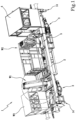
Figure 1 is a perspective view of a railway vehicle according to the invention; -
Figure 2 is a side view of the railway vehicle ofFigure 1 ; -
Figure 3 is an exploded view of the railway vehicle ofFigure 1 ; -
Figure 4 is an enlarged detail of the railway vehicle ofFigure 1 ; -
Figure 5 is a cross section, according to a vertical plane, of a detail of the railway vehicle according to the invention; -
Figure 6 is a perspective view of a first separable component of the railway vehicle according to the invention; -
Figure 7 is a perspective view of a second separable component of the railway vehicle according to the invention. - With reference to the accompanying drawings, the
numeral 1 denotes in its entirety a railway vehicle according to the invention. - The
vehicle 1 comprises amain frame 2 provided with tworailway axles 3 for travelling on a railway track. The number of axles is not, however, limited, as it may be even more than two and, if necessary, defined by one or more dollies where necessary, although in light of an optimisation of weights and dimensions the two-axis solution is preferable. - At a first end, the
vehicle 1 comprises a driver'scab 4 preferably fixed and which can be made, for example, according to known methods. - The remaining part of the main frame 2 (or part of it) defines at the top a work or
loading platform 5. - According to the invention, the
work platform 5 is configured for installing a plurality of operating units "W1-W3" to perform respective operations linked to the construction, overhaul and maintenance of the railway lines. In more detail, the operating units "W1-W3" are mounted or can be mounted on thework platform 5 independently of each other and according to different configurations and/or combinations depending on the needs present each time. - For this purpose, the
work platform 5 has a plurality of receivingareas 6 positioned one after another along a longitudinal axis of thevehicle 1 and preferably adjacent to each other. According to the embodiment illustrated there are four receiving areas, however the number may be different, in particular greater for heavier and structured vehicles or smaller for more agile and lighter vehicles. - These
receiving areas 6 are configured for rapid assembly and removal of the operating units "W1-W3". - As shown in
Figures 3 and4 , each receiving area "R" comprises a pair ofparallel guides 7, positioned perpendicularly to the longitudinal axis of the vehicle 1 (therefore to the direction of travel) and designed to allow an application, by lateral sliding, of an operating unit "W1-W3" to the receiving area "R". For this purpose, theparallel guides 6 may extend for the entire width of thework platform 5. - In more detail, as shown in the detail of
Figure 5 , eachguide 6 has the shape of a "C" with a front recess, facing towards theguide 6 opposite the same pair of guides, in such a way that between the two mutually facing recesses the operating unit "W" is guided or, preferably, aslidable plate 7 of the operating unit "W1-W3". - More preferably, the lateral sliding of the operating unit "W1-W3" is achieved by means of a motor-driven system which, according to the embodiment of
Figure 5 , comprises arack 8 positioned on at least one of theguides 6 and a motor-drivenpinion 9 positioned on theslidable plate 7 of the operating unit "W1-W3" and engageable with therack 8 for making a controlled sliding of the operating unit "W1-W3" along theguides 6 during assembly and removal of the operating unit "W1-W3" relative to thework platform 5. - Preferably, the
pinion 9 is connected to a motor orgear motor 10 with a vertical axis of rotation, mounted on theslidable plate 7. - According to the invention, the operating units "W1-W3" comprise two or more between: a crane "W1", an aerial work platform (lift) "W2", a reel unwinding device (not illustrated), a concrete mixer (not illustrated).
- The operating units "W1-W3" may also comprise an auxiliary driver's cab (W3), which can be used in a transfer configuration but advantageously removable if the
vehicle 1 is connected to further carriages and, therefore, the auxiliary cabin is unnecessary or an obstruction. - The
vehicle 1 made in this way therefore achieves a possibility of modular composition of the operating units "W1-W3" which therefore constitute to all intents and purposes the modular components of thevehicle 1. - Preferably, the work platform has at least two, preferably four receiving areas "R", of which at least two of identical structure configured to receive at least two operating units "W1-W3" according to different configurations and/or combinations in such a way that the operating units "W1-W3" can be exchanged with each other. In the example illustrated, the unit with crane "W1" and the aerial work platform (lift) "W2" are interchangeable with each other but the second requires the occupation of an adjacent receiving area "R" being larger in size.
- Preferably, at least two receiving areas "R" have
parallel guides 6 positioned at a respective spacing different to each other to adapt to operating units "W1-W3" of different types. For example, the unit with a crane may require a spacing less than the reel unwinding unit. - More generally speaking, the receiving areas "R" comprise one or more receiving areas provided with
parallel guides 6 positioned at a first spacing value (for example, a lower spacing, for operating units with cranes) and one or more second receiving areas provided withparallel guides 6 positioned at a second spacing value (for example, a greater spacing for the aerial work platform) and, if necessary, a third receiving area with intermediate spacing positioned at the end for receiving the auxiliary driver's cab. - In order to optimise the dimensions, adjacent receiving areas "R" may have
respective guides 6 placed side by side in such a way that the above-mentioned recesses of the guides are positioned in opposite directions. - Moreover, according to the invention, the
vehicle 1 comprises a plurality of functional units "F1-F4" mounted or which can be mounted below themain frame 2 and designed to supply the power necessary for moving therailway vehicle 1 and for powering the operating units "W1-W3". - In particular, the functional units "F1-F4" comprise at least one hydraulic unit "F1", a pneumatic unit "F2", a battery accumulator unit "F3" and a generator unit "F4". The generating unit "F4" comprises an internal combustion engine connected to an alternator for recharging batteries of the battery accumulator unit "F3". One or more of the functional units "F1-F4", preferably each of them, is independently mountable and removable relative to the
main frame 2 and, for that purpose, is housed in arespective containment frame 11 individually applicable below themain frame 2, and removable or extractable from it, to perform maintenance operations on the functional unit "F1-F4". - More specifically, one or more of the functional units "F1-F4", for example each of them, is slidable in a lateral direction, like a drawer, from and inside a respective fixed box-
shaped counterframe 20 for being extracted and re-inserted quickly and easily in the case of maintenance. - In more detail, each functional unit "F1-F4" is entirely housed in a box-shaped containment frame 11 (
Figures 3 and6 ) and is equipped with electrical, pneumatic and/or hydraulic connections for connection to themain frame 2 and/or to the operating units "W1-W3". - According to the specific embodiment illustrated, at least two functional units "F2, F3" (pneumatic and battery accumulators), and preferably also a third (hydraulic, "F1") are of the sliding type described above whilst one of them, in particular the generating unit "F4", can be inserted from above in a corresponding
fixed counterframe 30 applied to themain frame 2 below it and configured in the form of a "cradle". For this purpose, the main frame 2 (therefore, the work platform 5) has at least one suitable opening to allow the passage at least of said functional unit "F4". - Despite this, it is preferable that the laterally slidable functional units "F1-F4" can also be removed and reinserted from above (as well as being laterally extractable by sliding) and, therefore, for this purpose, the main frame 2 (therefore, the work platform 5) has suitable openings to allow the passage of said functional units "F1-F4" (
Figure 3 ), moved for example with the same crane forming part of an operating unit and mounted on thework platform 5. Each opening of themain frame 2 therefore corresponds to a respective lowerfixed frame 20, which also performs the function of supporting the respective laterally extractable functional unit (thefixed frame 20 being in this case configured both in the form of a cradle and a drawer), -
Figure 6 shows in detail the generating unit "F4" where theinternal combustion engine 15, thealternator 16, thetank 17, anelectrical panel 18 and aradiator 19 can be seen, as well as ananti-particulate filter 20. All these components are housed inside the box-shaped frame 11, which is in turn contained in the respective counterframe 30 (Figure 3 ). - In accordance with another aspect of the invention, the
main frame 2 is equipped, at the ends, with stabilising and liftingactuators 14 for stabilising the vehicle during use of the crane or other accessories which generate a tipping moment or for lifting thevehicle 1 relative to the ground in such a way as to removeaxles 12 of thevehicle 1 or carry out other operations below thevehicle 1. For this purpose,Figure 7 shows anaxle 12 of thevehicle 1 coupled to a respectivemechanical transmission 13 of the suspended type and to the electric traction motor M, which is removable in a simple manner after the lifting of thevehicle 1 by theactuators 14. - The present invention achieves the preset aims, overcoming the disadvantages of the prior art.
- The railway vehicle according to the invention is provided with electric traction and batteries for a completely electric operation, wherein the energy is guaranteed by an internal combustion engine connected to an alternator. The
vehicle 1 can therefore adopt a running configuration (transfer) using the energy generated by the internal combustion engine connected to the alternator, which in turn charges the batteries on board. The stored energy is then used during work, in the absence of high voltage electricity, allowing the use of the operational units for several hours in fully electric mode. - The
vehicle 1 is also equipped with a braking system connectable to carriages or other vehicles equipped with a continuous brake, allowing thevehicle 1 to be towed and in turn to tow all the vehicles of the type in use by railway personnel for the maintenance of the electrical traction systems and, in general, of all the vehicles equipped with an continuous and automatic brake system. - In the configuration illustrated in the accompanying drawings, the vehicle comprises a "tare" configuration, including accessories or ballast, of 25 tonnes and a "loading" configuration of 40 tonnes for an exceptional load situation (e.g. loaded concrete mixer).
- Moreover, the
vehicle 1 is configured to be transported with a flatbed trailer with a maximum height of 700 mm from the road surface in such a way as fall within the standard road profile in height and width. In particular, the maximum height of thevehicle 1, considering the wheels without wear and the suspensions compressed with the tare load, is 3.30 m from the upper surface of the track, a total height of 4.00 metres is thus reached during transport and falls within the limits required by the highway code, allowing the use of a non-exceptional transport. The maximum width of thevehicle 1 does not exceed 2.54 m and in this case, too, remains within the gauge limits for non-exceptional road transport. - The vehicle is also easy to maintain because the elements which make up the functional macro-areas of the vehicle are positioned in box-shaped frames extractable from the frame of the vehicle.
- Moreover, the use of a traction system with electric motors allows a simple power connection between the generating unit and the electric motors by means of simple electrical cables without requiring mechanical power connections, thus considerably simplifying maintenance operations.
- Moreover, according to a possible solution, the guides can be moved in such a way as to achieve different configurations suitable for modifying the layout of the possible combinations of the operating units on the work platform of the vehicle.
Claims (11)
- A multi-purpose self-propelled railway vehicle designed for the construction, repair and maintenance of railway lines, comprising a main frame (2) equipped with at least two axles (3) and forming at the top a work platform (5), a driver's cab (4) positioned at a first end of the main frame (2), a plurality of operating units (W1-W3) mounted or mountable on the work platform (5) for performing respective operations linked to the construction, repair and maintenance of the railway lines, and a plurality of functional units (F1-F4) mounted or mountable below the main frame (2) and intended for supplying the power necessary for moving the railway vehicle (1) and for powering the operating units (W1-W3), wherein said operating units (W1-W3) are applicable to the main frame (2), and can be removed from it, independently from each other and preferably modular for modifying the configuration of the vehicle (1) as a function of the operations to be performed characterized in that each of said functional units (F1-F4) is housed in a respective containment frame (11) individually applicable below the main frame (2), and removable or extractable from it, in order to perform maintenance operations on the functional unit (F1-F4).
- The railway vehicle according to claim 1, wherein each functional unit (F1-F4) is entirely housed in a box-shaped containment frame (11), is equipped with electrical, pneumatic and/or hydraulic connections for connection to the operating units (W1-W3), and is connected to the main frame (2), preferably with a side sliding box.
- The railway vehicle according to claim 1 or 2, wherein said functional units (F1-F4) comprise at least a hydraulic unit (F1), a pneumatic unit (F2), a battery accumulators unit (F3) and a generator unit (F4); said generator unit (F4) comprising an internal combustion engine (15) connected to an alternator (16) for recharging the batteries of said battery accumulators unit (F3).
- The railway vehicle according to any one of the preceding claims, wherein said work platform (2) has a plurality of receiving areas (R) positioned one after another along a longitudinal axis of the vehicle (1).
- The railway vehicle according to any one of the preceding claims, wherein said work platform (2) has at least two receiving areas (R) of identical structure configured to receive at least two of said operating units (W1-W3) according to different configurations and/or combinations in such a way that said at least two operating units (W1-W3) can be exchanged with each other.
- The railway vehicle according to claim 4 or 5, wherein each receiving area (R) comprises a pair of parallel guides (6) to allow an application, by lateral sliding, of an operating unit (W1-W3) to said receiving area (R); said parallel guides (6) being transversal, preferably perpendicular, to the direction of travel of the railway vehicle (1).
- The railway vehicle according to claim 6, comprising one or more first receiving areas (R) equipped with parallel guides (6) positioned at a first spacing value and one or more second receiving areas (R) equipped with parallel guides (6) positioned at a second spacing value different from said first spacing value, preferably, moreover, one or more first third receiving devices areas (R) equipped with parallel guides (6) positioned at a third spacing value different from said first and second spacing values.
- The railway vehicle according to claim 6 or 7, wherein at least one guide (6) of each receiving area (R) comprises a rack (8) and wherein each operating unit (W1-W3) comprises a motor-driven pinion (9) which can engage with said rack (8) for sliding the operating unit (W1-W3) along the guides (6) during assembly and removal of the operating unit (W1-W3) relative to the work platform (2); preferably said pinion (9) being connected to a motor or gear motor (10) with a vertical axis of rotation.
- The railway vehicle according to any one of claims 6 to 8, wherein each operating unit (W1-W3) comprises a movable plate (7) slidably insertable inside a recess made in each of said parallel guides (6), preferably each of said guides (6) being C-shaped in such a way as to define said recess.
- The railway vehicle according to any one of the preceding claims, wherein said operating units (W1-W3) comprise two or more between: a crane, an aerial work platform, a reel unwinder, a concrete mixer, an auxiliary driver's cab.
- The railway vehicle according to any one of the preceding claims, wherein said main frame (2) is equipped, at both ends, with stabilising and lifting actuators (14) configured for stabilising the vehicle (1) and/or lifting relative to the ground in such a way as to carry out a removal of the axles (12) of said railway vehicle (1).
Applications Claiming Priority (2)
| Application Number | Priority Date | Filing Date | Title |
|---|---|---|---|
| IT102021000015068A IT202100015068A1 (en) | 2021-06-09 | 2021-06-09 | Multipurpose self-propelled railway vehicle |
| PCT/IB2022/054998 WO2022259079A1 (en) | 2021-06-09 | 2022-05-27 | Multi-purpose self-propelled railway vehicle |
Publications (3)
| Publication Number | Publication Date |
|---|---|
| EP4351948A1 EP4351948A1 (en) | 2024-04-17 |
| EP4351948B1 true EP4351948B1 (en) | 2025-05-21 |
| EP4351948C0 EP4351948C0 (en) | 2025-05-21 |
Family
ID=77627315
Family Applications (1)
| Application Number | Title | Priority Date | Filing Date |
|---|---|---|---|
| EP22729302.4A Active EP4351948B1 (en) | 2021-06-09 | 2022-05-27 | Multi-purpose self-propelled railway vehicle |
Country Status (4)
| Country | Link |
|---|---|
| EP (1) | EP4351948B1 (en) |
| ES (1) | ES3035891T3 (en) |
| IT (1) | IT202100015068A1 (en) |
| WO (1) | WO2022259079A1 (en) |
Cited By (1)
| Publication number | Priority date | Publication date | Assignee | Title |
|---|---|---|---|---|
| EP4392303A1 (en) * | 2021-08-24 | 2024-07-03 | Plasser & Theurer, Export von Bahnbaumaschinen, Gesellschaft m.b.H. | Work vehicle for carrying out works on a track |
Citations (3)
| Publication number | Priority date | Publication date | Assignee | Title |
|---|---|---|---|---|
| EP1889770A1 (en) | 2006-08-17 | 2008-02-20 | Schörling-Brock GmbH | Train for construction and maintenance of rails on tracks, comprising at least one vehicle |
| EP2524849A1 (en) | 2011-05-17 | 2012-11-21 | KIROW ARDELT GmbH | Railway crane |
| CN206871066U (en) | 2017-06-20 | 2018-01-12 | 宝鸡中车时代工程机械有限公司 | Contact net synthesis upkeep operation car based on hybrid power transmission |
Family Cites Families (3)
| Publication number | Priority date | Publication date | Assignee | Title |
|---|---|---|---|---|
| CZ6226U1 (en) * | 1997-05-07 | 1997-06-24 | Bedřich Ing. Pospíšil | Working rail vehicle |
| CZ8040U1 (en) * | 1998-10-06 | 1998-11-16 | Bedřich Ing. Pospíšil | Integrated track-building machine |
| RU13783U1 (en) * | 1999-11-29 | 2000-05-27 | Открытое акционерное общество "Уральский научно-исследовательский и проектный институт медной промышленности "Унипромедь" | TRAVELING MACHINE |
-
2021
- 2021-06-09 IT IT102021000015068A patent/IT202100015068A1/en unknown
-
2022
- 2022-05-27 ES ES22729302T patent/ES3035891T3/en active Active
- 2022-05-27 EP EP22729302.4A patent/EP4351948B1/en active Active
- 2022-05-27 WO PCT/IB2022/054998 patent/WO2022259079A1/en not_active Ceased
Patent Citations (3)
| Publication number | Priority date | Publication date | Assignee | Title |
|---|---|---|---|---|
| EP1889770A1 (en) | 2006-08-17 | 2008-02-20 | Schörling-Brock GmbH | Train for construction and maintenance of rails on tracks, comprising at least one vehicle |
| EP2524849A1 (en) | 2011-05-17 | 2012-11-21 | KIROW ARDELT GmbH | Railway crane |
| CN206871066U (en) | 2017-06-20 | 2018-01-12 | 宝鸡中车时代工程机械有限公司 | Contact net synthesis upkeep operation car based on hybrid power transmission |
Non-Patent Citations (75)
| Title |
|---|
| ANONYMOUS: "B e t r i e b s a n l e i t u n g für MPV Powerlines mit Bühne und Kran", SPL POWERLINES GMBH & CO. KG, 5 November 2009 (2009-11-05), XP093372274 |
| ANONYMOUS: "ERSATZTEILKATALOG / SPARE PART CATALOG - POWERPACK 6 H 1800 R85L", MTU, 1 January 2013 (2013-01-01), XP093372291 |
| ANONYMOUS: "Groundbreaking factory train to cut years off Great Western electrification", NETWORKRAIL, 25 July 2013 (2013-07-25), XP093372313, Retrieved from the Internet <URL:https://www.networkrailmediacentre.co.uk/news/groundbreaking-factory-train-to-cut-years-off-great-western-electrification#> |
| ANONYMOUS: "Handbook for Stationary Vented Lead-Acid Batteries - Installation, Commissioning and Operation", GNB, 1 January 2012 (2012-01-01), XP093372292 |
| ANONYMOUS: "Katalog Ersatzteillisten, Baugruppenzeichnungen ,Elektro-/ Fluidpläne sowie Zuliefer-Unterlagen für MPV Powerline mit Bühne und Kran", WINDHOFF BAHN- UND ANLAGENTECHNIK GMBH, 5 November 2009 (2009-11-05), XP093372280 |
| ANONYMOUS: "MPV Powerlines mit Bühne und Kran (Module)", SPL POWERLINES GMBH & CO. KG, 4 November 2009 (2009-11-04), XP093372276 |
| ANONYMOUS: "MTU_ValueService Technical Documentation - PowerPack 6 H 1800 R85L - Betriebsanleitung MA15147/00D", MTU, 1 January 2012 (2012-01-01), XP093372287 |
| D10 - Zeichnung „Kraftstofftank" 21.10.2009 |
| D11 - Zeichnung „Pneumatikgerüst" 21.10.2009 |
| D12 - Zeichnung „Grundrahmen Hubsäule" 21.01.2009 |
| D13 - Zeichnung „Container" 27.04.2009 |
| D14 - Zeichnung „Antriebsaggregat" 1 29.10.2008 |
| D15 - Zeichnung „Antriebsaggregat" 2 21.04.2009 |
| D16 - Zeichnung „Antriebsstrang" 15.03.2007 |
| D17 - Zeichnung „Batteriekasten" 05.09.2007 |
| D18 - Zeichnung „MPV" 23.05.2008 |
| D19 - KAUFVERTRAG 06.05.2008 |
| D20 - EG-KONFORMITÄTSERKLÄRUNG 05.11.2009 |
| D21 - AUFTRAG 14.12.2011 |
| D22 - ANZAHLUNGSAUFFORDERUNG 1 08.02.2013 |
| D23 - ANZAHLUNGSAUFFORDERUNG 2 07.07.2014 |
| D24 - ANZAHLUNGSAUFFORDERUNG 3 28.07.2014 |
| D25 - RECHNUNG 31.10.2014 |
| D26 - Eidesstattliche Versicherung 23.02.2026 |
| D27 - MAGAZIN „MODERN RAILWAYS" 08.2013 |
| D28 - Artikel „Rail Engineer" 03.10.2014 |
| D29 - Artikel „Network Rail" 25.07.2013 |
| D30 - EC DECLARATION 07.07.2014 |
| D31 - TECHNISCHE UND FUNKTIONALE BESCHREIBUNG ZUR AUFTRAGSNUMMER 101010301 14.11.2013 |
| D32 - Zeichnung „Zugverband" 11.04.2012 |
| D33 - Zeichnung „Fahrzeug" 05.06.2014 |
| D34 - Zeichnung „Fahrzeug" 2 19.12.2013 |
| D35 - ERSATZTEILSTÜCKLISTE ZUR MATERIALNUMMER 1050300000770 04.01.2012 |
| D36 - Zeichnung „Aufbauten" 27.03.2012 |
| D37 - Zeichnung „Kabine" 11.04.2007 ???????????????????? |
| D38 - ERSATZTEILSTÜCKLISTE ZUR MATERIALNUMMER 1040300000281 24.01.2012 |
| D39 - Zeichnung Arbeitsbühne 07.2014 |
| D4 - ANSCHREIBEN ZUR VERÖFFENTLICHUNG DER D1.1 BIS D1.3 UND DER D1.8 BIS D1.11 |
| D40 - Hydraulikplan 17.07.2014 |
| D40 - Zeichnung „Fahrzeugrahmen" 09.02.2012 |
| D41 - Bedienungsanleitung Trommelblock 08.2013 |
| D41 - Elektropläne 12 V zum Auftrag 101010301 1 03.09.2014 |
| D42 - Elektropläne 400 V zum Auftrag 101010301 03.09.2014 |
| D42 - Zeichnung „Pneumatikgerüst" 2 01.12.2012 |
| D43 - Elektropläne 12 V zum Auftrag 101010301 2 27.03.2014 |
| D43 - ERSATZTEILSTÜCKLISTE ZUR MATERIALNUMMER 1040300014211 01.02.2012 |
| D44 - Zeichnung „Powerpack" 28.03.2012 |
| D45 - ERSATZTEILSTÜCKLISTE ZUR MATERIALNUMMER 1040300014597 13.03.2012 |
| D45 - ZUTEILUNGSLISTE POWERPACKS ZU FAHRZEUGEN 07.2014 |
| D46 - Zeichnung „Behälter" 12.04.2012 |
| D47 - ERSATZTEILSTÜCKLISTE ZUR MATERIALNUMMER 1040300014646 26.03.2012 |
| D48 - STRUKTURKENNZEICHENÜBERSICHT ZUM AUFTRAG 101010301 01.07.2014 |
| D48 - Zeichnung „Hydraulikölbehälter" 02.03.2012 |
| D49 - Zeichnung „Kraftstoffbehälter" 13.03.2012 |
| D5 - ERSATZTEILSTÜCKLISTE ZUR MATERIALNUMMER 1050300000339 20.10.2009 |
| D50 - Zeichnung „Batteriekasten" 2 28.02.2012 |
| D51 - ERSATZTEILSTÜCKLISTE ZUR MATERIALNUMMER 1040300014532 28.02.2012 |
| D52 - Ersatzteilstückliste zur Materialnummer 1040300014663 27.03.2012 |
| D53 - Zeichnung „Fahrzeug" 27.02.2012 |
| D54 - ERSATZTEILSTÜCKLISTE ZUR MATERIALNUMMER 1040300014663 27.03.2012 |
| D55 - Zeichnung „Container" 2 03.04.2012 |
| D56 - ANGEBOT TRAKTIONSBATTERIE 05.03.202 |
| D56 - ERSATZTEILSTÜCKLISTE ZUR MATERIALNUMMER 1040300014913 11.05.2012 |
| D57 - ERSATZTEILSTÜCKLISTE ZUR MATERIALNUMMER 1040300014561 05.03.2012 |
| D58 - ERSATZTEILSTÜCKLISTE ZUR MATERIALNUMMER 1040300014998 23.05.2012 |
| D59 - ERSATZTEILSTÜCKLISTE ZUR MATERIALNUMMER 1040300014208 01.02.2012 |
| D7 - ARCHIVE.ORG-SCREENSHOT ZUM VERÖFFENTLICHUNGSDATUM DER D1.6 |
| D8 - Zeichnung „Twistlock" 21.10.2009 |
| D9 - Zeichnung „Rahmen" 21.10.2009 |
| DITTUS HOLGER, HÜLSEBUSCH DIRK, UNGETHÜM JÖRG: "Reducing DMU fuel consumption by means of hybrid energy storage", EUROPEAN TRANSPORT RESEARCH REVIEW, vol. 3, no. 3, 1 November 2011 (2011-11-01), pages 149 - 159, XP093372306, ISSN: 1867-0717, DOI: 10.1007/s12544-011-0053-6 |
| KACHE MARTIN, UWE STEGLICH: "Simulation kombinierter Hybrid-konfiguration für Dieseltriebwagen", ETR, vol. 1 2, 1 January 2015 (2015-01-01), pages 44 - 49, XP093372308 |
| KACHE MARTIN: "Diesel-Hybrid-Triebwagen 50", ETR, 1 December 2014 (2014-12-01), pages 50 - 53, XP093372297 |
| KACHE MARTIN: "Hybridlokprojekte – Ein globaler Überblick", ETR, vol. 10, 1 October 2014 (2014-10-01), pages 32 - 36, XP093372303 |
| MÜLLER DETLEF: "Neues Plattformkonzept für Wartungsfahrzeuge", INDUSTRIEFORUM, 10 June 2015 (2015-06-10), XP093372294 |
| STACY MUNGO: "Great Western Electrification - Arrival of the new High Output Plant System", RAILENGINEER, 3 October 2014 (2014-10-03), XP093372310, Retrieved from the Internet <URL:https://www.railengineer.co.uk/great-western-electrification-arrival-new-high-output-plant-system/> |
Cited By (1)
| Publication number | Priority date | Publication date | Assignee | Title |
|---|---|---|---|---|
| EP4392303A1 (en) * | 2021-08-24 | 2024-07-03 | Plasser & Theurer, Export von Bahnbaumaschinen, Gesellschaft m.b.H. | Work vehicle for carrying out works on a track |
Also Published As
| Publication number | Publication date |
|---|---|
| IT202100015068A1 (en) | 2022-12-09 |
| WO2022259079A1 (en) | 2022-12-15 |
| EP4351948C0 (en) | 2025-05-21 |
| EP4351948A1 (en) | 2024-04-17 |
| ES3035891T3 (en) | 2025-09-10 |
Similar Documents
| Publication | Publication Date | Title |
|---|---|---|
| EP2440431B1 (en) | Heavy-duty ground transportation vehicle, in particular an unmanned heavy-duty transportation vehicle for iso containers | |
| DE102012108769A1 (en) | Battery Electric Tractor Trailer for ISO Container Transport | |
| DE102012108768A1 (en) | Battery Electric Tractor Trailer for ISO Container Transport | |
| CN101855106B (en) | Heavy-duty transport modular vehicles especially for ports | |
| US20110052364A1 (en) | apparatus and method for handling railway rails | |
| EP2694424B1 (en) | Straddle carrier device comprising electric drives | |
| US20120217074A1 (en) | All-Electric Powered Vehicle | |
| CA3123163C (en) | Motorized rail car | |
| EP4351948B1 (en) | Multi-purpose self-propelled railway vehicle | |
| CA2883026C (en) | Work machine, in particular dump truck or truck | |
| CN117325816A (en) | Array type power exchange station and energy station | |
| CN102458894A (en) | Automotive power generation module device | |
| EP4032776B1 (en) | Energy-supplying double-decker carriage, rail vehicle and method of manufacturing a double-decker carriage | |
| JP2019069715A (en) | Self-propelled multiple spindle dolly | |
| CN208101806U (en) | A kind of bypass cable vehicle | |
| DE102011018812A1 (en) | Industrial truck, in particular counterbalance forklift | |
| CN119190096A (en) | A rail-type flatbed crane for loading a movable crane | |
| GB2549489A (en) | Convertible electric rail carriage | |
| US20260084511A1 (en) | Device for inserting and/or removing a power unit | |
| CN218968719U (en) | Track panel laying and replacing vehicle | |
| US20030189329A1 (en) | Combination hauling vehicle and low boy trailer and trailer with outrigger assembly | |
| CN214653389U (en) | Self-driven large-tonnage bearing trolley | |
| EP3995334A1 (en) | Electrobus | |
| CN218786019U (en) | Bridge steel transfer flat car | |
| CN200967432Y (en) | Self loading-unloading maintenance vehicle for electric automobile |
Legal Events
| Date | Code | Title | Description |
|---|---|---|---|
| STAA | Information on the status of an ep patent application or granted ep patent |
Free format text: STATUS: UNKNOWN |
|
| STAA | Information on the status of an ep patent application or granted ep patent |
Free format text: STATUS: THE INTERNATIONAL PUBLICATION HAS BEEN MADE |
|
| PUAI | Public reference made under article 153(3) epc to a published international application that has entered the european phase |
Free format text: ORIGINAL CODE: 0009012 |
|
| STAA | Information on the status of an ep patent application or granted ep patent |
Free format text: STATUS: REQUEST FOR EXAMINATION WAS MADE |
|
| 17P | Request for examination filed |
Effective date: 20231127 |
|
| AK | Designated contracting states |
Kind code of ref document: A1 Designated state(s): AL AT BE BG CH CY CZ DE DK EE ES FI FR GB GR HR HU IE IS IT LI LT LU LV MC MK MT NL NO PL PT RO RS SE SI SK SM TR |
|
| DAV | Request for validation of the european patent (deleted) | ||
| DAX | Request for extension of the european patent (deleted) | ||
| GRAP | Despatch of communication of intention to grant a patent |
Free format text: ORIGINAL CODE: EPIDOSNIGR1 |
|
| STAA | Information on the status of an ep patent application or granted ep patent |
Free format text: STATUS: GRANT OF PATENT IS INTENDED |
|
| INTG | Intention to grant announced |
Effective date: 20241223 |
|
| GRAS | Grant fee paid |
Free format text: ORIGINAL CODE: EPIDOSNIGR3 |
|
| GRAA | (expected) grant |
Free format text: ORIGINAL CODE: 0009210 |
|
| STAA | Information on the status of an ep patent application or granted ep patent |
Free format text: STATUS: THE PATENT HAS BEEN GRANTED |
|
| AK | Designated contracting states |
Kind code of ref document: B1 Designated state(s): AL AT BE BG CH CY CZ DE DK EE ES FI FR GB GR HR HU IE IS IT LI LT LU LV MC MK MT NL NO PL PT RO RS SE SI SK SM TR |
|
| REG | Reference to a national code |
Ref country code: GB Ref legal event code: FG4D |
|
| REG | Reference to a national code |
Ref country code: CH Ref legal event code: EP |
|
| REG | Reference to a national code |
Ref country code: DE Ref legal event code: R096 Ref document number: 602022014961 Country of ref document: DE |
|
| REG | Reference to a national code |
Ref country code: IE Ref legal event code: FG4D |
|
| PGFP | Annual fee paid to national office [announced via postgrant information from national office to epo] |
Ref country code: ES Payment date: 20250617 Year of fee payment: 4 |
|
| U01 | Request for unitary effect filed |
Effective date: 20250618 |
|
| PGFP | Annual fee paid to national office [announced via postgrant information from national office to epo] |
Ref country code: AT Payment date: 20250721 Year of fee payment: 4 |
|
| U07 | Unitary effect registered |
Designated state(s): AT BE BG DE DK EE FI FR IT LT LU LV MT NL PT RO SE SI Effective date: 20250627 |
|
| U20 | Renewal fee for the european patent with unitary effect paid |
Year of fee payment: 4 Effective date: 20250626 |
|
| REG | Reference to a national code |
Ref country code: ES Ref legal event code: FG2A Ref document number: 3035891 Country of ref document: ES Kind code of ref document: T3 Effective date: 20250910 |
|
| PG25 | Lapsed in a contracting state [announced via postgrant information from national office to epo] |
Ref country code: NO Free format text: LAPSE BECAUSE OF FAILURE TO SUBMIT A TRANSLATION OF THE DESCRIPTION OR TO PAY THE FEE WITHIN THE PRESCRIBED TIME-LIMIT Effective date: 20250821 Ref country code: GR Free format text: LAPSE BECAUSE OF FAILURE TO SUBMIT A TRANSLATION OF THE DESCRIPTION OR TO PAY THE FEE WITHIN THE PRESCRIBED TIME-LIMIT Effective date: 20250822 |
|
| PG25 | Lapsed in a contracting state [announced via postgrant information from national office to epo] |
Ref country code: PL Free format text: LAPSE BECAUSE OF FAILURE TO SUBMIT A TRANSLATION OF THE DESCRIPTION OR TO PAY THE FEE WITHIN THE PRESCRIBED TIME-LIMIT Effective date: 20250521 |
|
| PG25 | Lapsed in a contracting state [announced via postgrant information from national office to epo] |
Ref country code: HR Free format text: LAPSE BECAUSE OF FAILURE TO SUBMIT A TRANSLATION OF THE DESCRIPTION OR TO PAY THE FEE WITHIN THE PRESCRIBED TIME-LIMIT Effective date: 20250521 |
|
| PG25 | Lapsed in a contracting state [announced via postgrant information from national office to epo] |
Ref country code: RS Free format text: LAPSE BECAUSE OF FAILURE TO SUBMIT A TRANSLATION OF THE DESCRIPTION OR TO PAY THE FEE WITHIN THE PRESCRIBED TIME-LIMIT Effective date: 20250821 |
|
| PG25 | Lapsed in a contracting state [announced via postgrant information from national office to epo] |
Ref country code: IS Free format text: LAPSE BECAUSE OF FAILURE TO SUBMIT A TRANSLATION OF THE DESCRIPTION OR TO PAY THE FEE WITHIN THE PRESCRIBED TIME-LIMIT Effective date: 20250921 |
|
| REG | Reference to a national code |
Ref country code: CH Ref legal event code: H13 Free format text: ST27 STATUS EVENT CODE: U-0-0-H10-H13 (AS PROVIDED BY THE NATIONAL OFFICE) Effective date: 20251223 |
|
| PG25 | Lapsed in a contracting state [announced via postgrant information from national office to epo] |
Ref country code: SM Free format text: LAPSE BECAUSE OF FAILURE TO SUBMIT A TRANSLATION OF THE DESCRIPTION OR TO PAY THE FEE WITHIN THE PRESCRIBED TIME-LIMIT Effective date: 20250521 |
|
| PG25 | Lapsed in a contracting state [announced via postgrant information from national office to epo] |
Ref country code: CH Free format text: LAPSE BECAUSE OF NON-PAYMENT OF DUE FEES Effective date: 20250531 |
|
| PG25 | Lapsed in a contracting state [announced via postgrant information from national office to epo] |
Ref country code: CZ Free format text: LAPSE BECAUSE OF FAILURE TO SUBMIT A TRANSLATION OF THE DESCRIPTION OR TO PAY THE FEE WITHIN THE PRESCRIBED TIME-LIMIT Effective date: 20250521 |
|
| PG25 | Lapsed in a contracting state [announced via postgrant information from national office to epo] |
Ref country code: SK Free format text: LAPSE BECAUSE OF FAILURE TO SUBMIT A TRANSLATION OF THE DESCRIPTION OR TO PAY THE FEE WITHIN THE PRESCRIBED TIME-LIMIT Effective date: 20250521 |
|
| PG25 | Lapsed in a contracting state [announced via postgrant information from national office to epo] |
Ref country code: MC Free format text: LAPSE BECAUSE OF FAILURE TO SUBMIT A TRANSLATION OF THE DESCRIPTION OR TO PAY THE FEE WITHIN THE PRESCRIBED TIME-LIMIT Effective date: 20250521 |
|
| PLBI | Opposition filed |
Free format text: ORIGINAL CODE: 0009260 |
|
| REG | Reference to a national code |
Ref country code: CH Ref legal event code: L10 Free format text: ST27 STATUS EVENT CODE: U-0-0-L10-L00 (AS PROVIDED BY THE NATIONAL OFFICE) Effective date: 20260304 |
|
| PLAX | Notice of opposition and request to file observation + time limit sent |
Free format text: ORIGINAL CODE: EPIDOSNOBS2 |
|
| 26 | Opposition filed |
Opponent name: WINDHOFF BAHN- UND ANLAGENTECHNIK GMBH Effective date: 20260223 |
|
| PG25 | Lapsed in a contracting state [announced via postgrant information from national office to epo] |
Ref country code: IE Free format text: LAPSE BECAUSE OF NON-PAYMENT OF DUE FEES Effective date: 20250527 |