EP4351704B1 - System zur peripheren nervenstimulation - Google Patents
System zur peripheren nervenstimulation Download PDFInfo
- Publication number
- EP4351704B1 EP4351704B1 EP22732267.4A EP22732267A EP4351704B1 EP 4351704 B1 EP4351704 B1 EP 4351704B1 EP 22732267 A EP22732267 A EP 22732267A EP 4351704 B1 EP4351704 B1 EP 4351704B1
- Authority
- EP
- European Patent Office
- Prior art keywords
- recording
- recording means
- elements
- stimulation
- pattern
- Prior art date
- Legal status (The legal status is an assumption and is not a legal conclusion. Google has not performed a legal analysis and makes no representation as to the accuracy of the status listed.)
- Active
Links
Images


Classifications
-
- A—HUMAN NECESSITIES
- A61—MEDICAL OR VETERINARY SCIENCE; HYGIENE
- A61B—DIAGNOSIS; SURGERY; IDENTIFICATION
- A61B5/00—Measuring for diagnostic purposes; Identification of persons
- A61B5/24—Detecting, measuring or recording bioelectric or biomagnetic signals of the body or parts thereof
- A61B5/25—Bioelectric electrodes therefor
- A61B5/263—Bioelectric electrodes therefor characterised by the electrode materials
-
- A—HUMAN NECESSITIES
- A61—MEDICAL OR VETERINARY SCIENCE; HYGIENE
- A61B—DIAGNOSIS; SURGERY; IDENTIFICATION
- A61B5/00—Measuring for diagnostic purposes; Identification of persons
- A61B5/24—Detecting, measuring or recording bioelectric or biomagnetic signals of the body or parts thereof
- A61B5/25—Bioelectric electrodes therefor
- A61B5/279—Bioelectric electrodes therefor specially adapted for particular uses
- A61B5/291—Bioelectric electrodes therefor specially adapted for particular uses for electroencephalography [EEG]
- A61B5/293—Invasive
-
- A—HUMAN NECESSITIES
- A61—MEDICAL OR VETERINARY SCIENCE; HYGIENE
- A61B—DIAGNOSIS; SURGERY; IDENTIFICATION
- A61B5/00—Measuring for diagnostic purposes; Identification of persons
- A61B5/24—Detecting, measuring or recording bioelectric or biomagnetic signals of the body or parts thereof
- A61B5/25—Bioelectric electrodes therefor
- A61B5/279—Bioelectric electrodes therefor specially adapted for particular uses
- A61B5/294—Bioelectric electrodes therefor specially adapted for particular uses for nerve conduction study [NCS]
-
- A—HUMAN NECESSITIES
- A61—MEDICAL OR VETERINARY SCIENCE; HYGIENE
- A61B—DIAGNOSIS; SURGERY; IDENTIFICATION
- A61B5/00—Measuring for diagnostic purposes; Identification of persons
- A61B5/24—Detecting, measuring or recording bioelectric or biomagnetic signals of the body or parts thereof
- A61B5/30—Input circuits therefor
- A61B5/307—Input circuits therefor specially adapted for particular uses
- A61B5/311—Input circuits therefor specially adapted for particular uses for nerve conduction study [NCS]
-
- A—HUMAN NECESSITIES
- A61—MEDICAL OR VETERINARY SCIENCE; HYGIENE
- A61B—DIAGNOSIS; SURGERY; IDENTIFICATION
- A61B5/00—Measuring for diagnostic purposes; Identification of persons
- A61B5/24—Detecting, measuring or recording bioelectric or biomagnetic signals of the body or parts thereof
- A61B5/316—Modalities, i.e. specific diagnostic methods
- A61B5/388—Nerve conduction study, e.g. detecting action potential of peripheral nerves
-
- A—HUMAN NECESSITIES
- A61—MEDICAL OR VETERINARY SCIENCE; HYGIENE
- A61N—ELECTROTHERAPY; MAGNETOTHERAPY; RADIATION THERAPY; ULTRASOUND THERAPY
- A61N1/00—Electrotherapy; Circuits therefor
- A61N1/02—Details
- A61N1/04—Electrodes
- A61N1/0404—Electrodes for external use
- A61N1/0408—Use-related aspects
- A61N1/0452—Specially adapted for transcutaneous muscle stimulation [TMS]
-
- A—HUMAN NECESSITIES
- A61—MEDICAL OR VETERINARY SCIENCE; HYGIENE
- A61N—ELECTROTHERAPY; MAGNETOTHERAPY; RADIATION THERAPY; ULTRASOUND THERAPY
- A61N1/00—Electrotherapy; Circuits therefor
- A61N1/02—Details
- A61N1/04—Electrodes
- A61N1/0404—Electrodes for external use
- A61N1/0408—Use-related aspects
- A61N1/0456—Specially adapted for transcutaneous electrical nerve stimulation [TENS]
-
- A—HUMAN NECESSITIES
- A61—MEDICAL OR VETERINARY SCIENCE; HYGIENE
- A61N—ELECTROTHERAPY; MAGNETOTHERAPY; RADIATION THERAPY; ULTRASOUND THERAPY
- A61N1/00—Electrotherapy; Circuits therefor
- A61N1/02—Details
- A61N1/04—Electrodes
- A61N1/05—Electrodes for implantation or insertion into the body, e.g. heart electrode
- A61N1/0526—Head electrodes
- A61N1/0529—Electrodes for brain stimulation
- A61N1/0531—Brain cortex electrodes
-
- A—HUMAN NECESSITIES
- A61—MEDICAL OR VETERINARY SCIENCE; HYGIENE
- A61N—ELECTROTHERAPY; MAGNETOTHERAPY; RADIATION THERAPY; ULTRASOUND THERAPY
- A61N1/00—Electrotherapy; Circuits therefor
- A61N1/02—Details
- A61N1/04—Electrodes
- A61N1/05—Electrodes for implantation or insertion into the body, e.g. heart electrode
- A61N1/0526—Head electrodes
- A61N1/0529—Electrodes for brain stimulation
- A61N1/0534—Electrodes for deep brain stimulation
-
- A—HUMAN NECESSITIES
- A61—MEDICAL OR VETERINARY SCIENCE; HYGIENE
- A61N—ELECTROTHERAPY; MAGNETOTHERAPY; RADIATION THERAPY; ULTRASOUND THERAPY
- A61N1/00—Electrotherapy; Circuits therefor
- A61N1/02—Details
- A61N1/04—Electrodes
- A61N1/05—Electrodes for implantation or insertion into the body, e.g. heart electrode
- A61N1/0526—Head electrodes
- A61N1/0529—Electrodes for brain stimulation
- A61N1/0539—Anchoring of brain electrode systems, e.g. within burr hole
-
- A—HUMAN NECESSITIES
- A61—MEDICAL OR VETERINARY SCIENCE; HYGIENE
- A61N—ELECTROTHERAPY; MAGNETOTHERAPY; RADIATION THERAPY; ULTRASOUND THERAPY
- A61N1/00—Electrotherapy; Circuits therefor
- A61N1/02—Details
- A61N1/04—Electrodes
- A61N1/05—Electrodes for implantation or insertion into the body, e.g. heart electrode
- A61N1/0551—Spinal or peripheral nerve electrodes
- A61N1/0556—Cuff electrodes
-
- A—HUMAN NECESSITIES
- A61—MEDICAL OR VETERINARY SCIENCE; HYGIENE
- A61N—ELECTROTHERAPY; MAGNETOTHERAPY; RADIATION THERAPY; ULTRASOUND THERAPY
- A61N1/00—Electrotherapy; Circuits therefor
- A61N1/02—Details
- A61N1/04—Electrodes
- A61N1/06—Electrodes for high-frequency therapy
-
- A—HUMAN NECESSITIES
- A61—MEDICAL OR VETERINARY SCIENCE; HYGIENE
- A61N—ELECTROTHERAPY; MAGNETOTHERAPY; RADIATION THERAPY; ULTRASOUND THERAPY
- A61N1/00—Electrotherapy; Circuits therefor
- A61N1/18—Applying electric currents by contact electrodes
- A61N1/32—Applying electric currents by contact electrodes alternating or intermittent currents
- A61N1/36—Applying electric currents by contact electrodes alternating or intermittent currents for stimulation
- A61N1/36014—External stimulators, e.g. with patch electrodes
- A61N1/3603—Control systems
- A61N1/36031—Control systems using physiological parameters for adjustment
-
- A—HUMAN NECESSITIES
- A61—MEDICAL OR VETERINARY SCIENCE; HYGIENE
- A61N—ELECTROTHERAPY; MAGNETOTHERAPY; RADIATION THERAPY; ULTRASOUND THERAPY
- A61N1/00—Electrotherapy; Circuits therefor
- A61N1/18—Applying electric currents by contact electrodes
- A61N1/32—Applying electric currents by contact electrodes alternating or intermittent currents
- A61N1/36—Applying electric currents by contact electrodes alternating or intermittent currents for stimulation
- A61N1/3605—Implantable neurostimulators for stimulating central or peripheral nerve system
- A61N1/36128—Control systems
- A61N1/36135—Control systems using physiological parameters
- A61N1/36139—Control systems using physiological parameters with automatic adjustment
-
- A—HUMAN NECESSITIES
- A61—MEDICAL OR VETERINARY SCIENCE; HYGIENE
- A61N—ELECTROTHERAPY; MAGNETOTHERAPY; RADIATION THERAPY; ULTRASOUND THERAPY
- A61N1/00—Electrotherapy; Circuits therefor
- A61N1/18—Applying electric currents by contact electrodes
- A61N1/32—Applying electric currents by contact electrodes alternating or intermittent currents
- A61N1/36—Applying electric currents by contact electrodes alternating or intermittent currents for stimulation
- A61N1/3605—Implantable neurostimulators for stimulating central or peripheral nerve system
- A61N1/36128—Control systems
- A61N1/36135—Control systems using physiological parameters
- A61N1/3614—Control systems using physiological parameters based on impedance measurement
-
- A—HUMAN NECESSITIES
- A61—MEDICAL OR VETERINARY SCIENCE; HYGIENE
- A61N—ELECTROTHERAPY; MAGNETOTHERAPY; RADIATION THERAPY; ULTRASOUND THERAPY
- A61N1/00—Electrotherapy; Circuits therefor
- A61N1/18—Applying electric currents by contact electrodes
- A61N1/32—Applying electric currents by contact electrodes alternating or intermittent currents
- A61N1/36—Applying electric currents by contact electrodes alternating or intermittent currents for stimulation
- A61N1/3605—Implantable neurostimulators for stimulating central or peripheral nerve system
- A61N1/36128—Control systems
- A61N1/36146—Control systems specified by the stimulation parameters
- A61N1/36167—Timing, e.g. stimulation onset
- A61N1/36178—Burst or pulse train parameters
-
- A—HUMAN NECESSITIES
- A61—MEDICAL OR VETERINARY SCIENCE; HYGIENE
- A61N—ELECTROTHERAPY; MAGNETOTHERAPY; RADIATION THERAPY; ULTRASOUND THERAPY
- A61N1/00—Electrotherapy; Circuits therefor
- A61N1/18—Applying electric currents by contact electrodes
- A61N1/32—Applying electric currents by contact electrodes alternating or intermittent currents
- A61N1/36—Applying electric currents by contact electrodes alternating or intermittent currents for stimulation
- A61N1/372—Arrangements in connection with the implantation of stimulators
- A61N1/37211—Means for communicating with stimulators
- A61N1/37235—Aspects of the external programmer
- A61N1/37247—User interfaces, e.g. input or presentation means
-
- A—HUMAN NECESSITIES
- A61—MEDICAL OR VETERINARY SCIENCE; HYGIENE
- A61N—ELECTROTHERAPY; MAGNETOTHERAPY; RADIATION THERAPY; ULTRASOUND THERAPY
- A61N1/00—Electrotherapy; Circuits therefor
- A61N1/18—Applying electric currents by contact electrodes
- A61N1/32—Applying electric currents by contact electrodes alternating or intermittent currents
- A61N1/36—Applying electric currents by contact electrodes alternating or intermittent currents for stimulation
- A61N1/372—Arrangements in connection with the implantation of stimulators
- A61N1/375—Constructional arrangements, e.g. casings
- A61N1/37514—Brain implants
-
- A—HUMAN NECESSITIES
- A61—MEDICAL OR VETERINARY SCIENCE; HYGIENE
- A61N—ELECTROTHERAPY; MAGNETOTHERAPY; RADIATION THERAPY; ULTRASOUND THERAPY
- A61N1/00—Electrotherapy; Circuits therefor
- A61N1/40—Applying electric fields by inductive or capacitive coupling ; Applying radio-frequency signals
Definitions
- the present invention relates to a system for peripheral nerve stimulation (PNS), in particular for monitoring of neuronal and/or muscle activity.
- PNS peripheral nerve stimulation
- NVM nerve conduction velocity
- conduction velocities are affected by a wide range of factors, which include a.o. age, sex and various medical conditions. Studies allow for better diagnoses of various neuropathies, especially demyelinating diseases, as these conditions result in reduced or non-existent conduction velocities.
- NCV measurements use a stimulation pulse on e.g., the forearm, while measuring the response at a certain distance, e.g. at a distance of more than 10 cm.
- the velocity is relatively low compared to normal electrical propagation (order of the speed of light), e.g. 0.5 m/s for IV/C sensory fibers and up to 120 m/s for la sensory/alpha motor fibers.
- miniaturized electrode arrays such as nerve cuffsor small skin patches for peripheral nerve stimulation
- the distance is much smaller.
- the time to detect the delays in the course of the stimulation propagation along the corresponding nerve fibers is much shorter.
- WO2020/087123A1 discloses an implantable stimulator, e.g., an implantable spinal cord stimulator, inter alia adapted for estimating a nerve conduction velocity, said stimulator comprising at least one stimulation electrode and at least one measurement electrode, e.g., a plurality of measurement electrodes, a measurement circuitry for obtaining a neural measurement from the at least one measurement electrode, and a processor.
- an implantable stimulator e.g., an implantable spinal cord stimulator, inter alia adapted for estimating a nerve conduction velocity
- said stimulator comprising at least one stimulation electrode and at least one measurement electrode, e.g., a plurality of measurement electrodes, a measurement circuitry for obtaining a neural measurement from the at least one measurement electrode, and a processor.
- a system for peripheral nerve stimulation in particular for detecting and/or monitoring of neuronal and/or muscle activity, comprising at least one neurostimulation device, wherein the neurostimulation device comprises at least a first recording means and a second recording means, wherein the first recording means and the second recording means are configured to be arranged at a recording means distance from one another and respectively configured to detect/measure/determine a stimulus being propagated along a nervous structure, in particular along an efferent nerve and/or an afferent nerve, such that a speed of the stimulus being propagated along the nervous/nerve structure/fiber can be determined.
- the present invention is based on the idea to use an (pre-defined) arrangement of recording means, in particular an electrode or coil pattern, with known/defined distances and, optionally, known sensitivity differences, between the electrodes/coils, where those are preferably combined/connected into one common recording channel/connection.
- the invention can be considered to be basically inspired by the optical Fiber Bragg Grating concerning optical light reflection/transmission/wavelength shifts which have at least some parallels to induced currents in electrodes/coils with respective time-shifts.
- the propagating electrochemical impulse appears not only once but multiple times on the recording channel timeline/the common recording signal.
- the relative position between those pulses identifies the exact location of where the pulse appeared on the array/pattern/arrangement of recording means.
- such (common) recording signals do not only provide the propagation speed, but also e.g. the direction and thus the type of nerve/nervous structure/fiber which propagated the measured stimulus, i.e. efferent or afferent type of structures/sensors/fibers.
- the first and second recording means are preferably arranged at a recording means distance.
- the recording means distance can be a pre-defined and fixed distance between the first/second recording means.
- the distance between the first and second recording means being arranged on the patient's body can be measured and subsequently set, e.g. by corresponding input to a control unit of the system, as the recording means distance.
- the first/second recording means are configured to determine/detect/measure a stimulus being propagated along a nerve/nervous structure like a nerve fiber.
- a stimulus can be based on a natural neural/muscle activity or can be induced by an (external) neural stimulation.
- a run time of the propagated stimulus along the recording means distance can be determined.
- the speed of the propagated stimulus can be calculated on basis of the recording means distance and the run time of the propagated stimulus along such recording means distance.
- such configuration of the system i.e. of the first/second recording means, also allows to determine further information like the direction of nerve propagation and the kind of nervous structure/fiber propagating the respective stimulus.
- the system according to the present invention provides an easy to use and integral approach on how to proceed NCV measurement by using miniaturized recording/stimulation devices, as applied in PNS.
- the first and/or second recording means comprises at least two recording elements, wherein the recording elements of the first recording means are arranged in a first pattern, wherein the recording elements of the second recording means are arranged in a second pattern.
- first and/or second recording means can comprise two or more recording elements being arranged in a certain pattern. It is also possible that the first recording means comprise more or less recording elements than the second recording means.
- the first and second pattern can be identical.
- the first and second pattern deviate from each other.
- the first/second pattern can deviate in the structural/geometrical embodiment of the respective recording elements, the arrangement of the recording elements of the first/second recording means relative to each other and/or the like.
- the first and/or second recordings means can provide a specific signature during recording/detecting/measurement of a stimulus which can allow their identification on the (common) recording signal, as provided by the first/second recording means to e.g. the control unit of the system.
- the first pattern comprises a first recording element distance between the recording elements of the first recording element and the second pattern comprises a second recording element distance between the recording elements of the second recording means.
- the first recording element distance and the second recording element distance are identical or deviate from each other.
- the first and second pattern of the first/second recording means can preferably deviate from each other by the first/second recording element distance being provided between the at least two recording elements of each of the first/second recording means.
- the recording element distance between recording elements of the second recording means can be larger than in case of the first recording means.
- Such different recording elements distances can allow for a specific signature of the first and second recording means.
- the first and second recording means comprising individual patterns of recording elements, can be identified respectively, namely due to their unique, specific signature.
- Such signature e.g. by the first/second patterns of the first/second recording means, can, for example, provide an easier and beneficial signal processing.
- the first pattern and second pattern preferably deviate from each other only with respect to the first and second recording element distance.
- the first/second recording means can be easily identified.
- the first recording means and the second recording means provide a unique signature on the (common) recording signal, which reflects the propagation of the detected nerve stimulus, due to the different first/second recording elements distances being provided between their respective recording elements.
- each recording element is provided in form of at least one electrode or coil.
- the first/second recording means i.e. the respective recording elements
- the first/second recording means can be implemented as recording electrodes in a neurostimulation device for PNS.
- the first/second recording means i.e. the respective recording elements
- the first/second recording means can be provided in form of recording coils, e.g. in a corresponding nerve cuff for PNS.
- the neurostimulation device can be provided as an electrode device or as a coil device.
- the system in particular the corresponding recording means, can be implemented in various different ways as well as in an efficient and appropriate manner for the respective field of application.
- the neurostimulation device comprises at least one stimulation means for transmitting stimulation signals to a patient's tissue in order to initiate neuronal and/or muscle stimulation, preferably being configured in form of at least one electrode or coil.
- the neurostimulation device of the system according to the present invention can be provided as an electrode device comprising at least one stimulation electrode and at least two recording means, preferably each comprising at least two electrodes as recording elements being arranged in a first/second pattern.
- the stimulations means can be implemented as a stimulation coil, preferably in combination with recording means, i.e. recording elements, being implemented in form of coils as well.
- the stimulation means can be provided in form of at least one electrode whereby the recoding elements are provided in form of at least one coil respectively, or vice versa.
- the system comprising the neurostimulation device having at least one stimulation means, can be used in applications like deep brain stimulation or peripheral nerve stimulation. Due to the specific implementation of the recording means, the system can be further used, alternatively or in parallel to the stimulation application itself, for NCV measurements.
- the system can be used to detect/measure/determine a natural neural activity as well as a (neuro-)stimulation induced activity can be provided via the stimulation means for execution of an NCV measurement.
- first recording means and the second recording means in particular recording elements of the first recording means and recording elements of the second recording means, comprise different recording sensitivities.
- the recording elements of one of the recording means can comprise same or different recording sensitivities.
- the recording sensitivities of the recording elements of one recording means can be equal, while recording sensitivities of the first and second recording means differ.
- each recording element of the system comprises a different/unique recording sensitivity.
- the recording/measurement/detection signal as forwarded by the recording means i.e. the respective recording elements, can differ in case of one stimulus being detected/determined due to the different recording sensitivities.
- the first/second recording means can provide different signatures, not only with respect to time shifts within the (common) recording signal, but also with respect to the intensity of the recording signal being provided by the recording means due to their recording sensitivity.
- system further comprises a control unit being configured to operate, in particular to control and/or regulate the operation of, the neurostimulation device and/or to provide signal processing of the signals as received from the first and second recording means.
- the control unit can receive the (common) recording signal(s) from the first/second recording means for subsequent signal processing.
- the control unit can be configured to analyze the recording signal in order to determine measured/detected stimulus along the recording signal and/or to determine a time between the detection of the stimulus by the first and second recording means.
- control unit can calculate the nerve conducting velocity based on the (common) recording signal(s) received.
- control unit can be provided in combination with input means and output means of the system, e.g. to allow a user to provide input concerning the recording means distance and/or the first/second recording element distance. Via the output means, the control unit can provide the results of the NCV measurement to the user, namely the speed of the propagated stimulus as measured/detected by the recording means.
- a recording signal from the first and/or second recording means, in particular of the recording elements of the first and/or second recording means, is forwarded via a common signal connection, preferably to a control unit of the system.
- the recording signals of the single recording elements can be combined to one single, common signal connection.
- the recording signals can be considered to be combined to a common recording signal.
- the common signal connection can be provided as a (data) communicative and/or electrical connection between the recording means, i.e. the recording elements, to the control unit of the system, a data storage, a communication device for further forwarding of the recording signal, to an external server or the like.
- means for combining the recording signals of the single recording elements of the first/second recording means to a combined recording signal can be provided in order to forward a single combined recording signal via the common signal connection.
- the infrastructure of the system in particular in the vicinity of the patient and with regard to the arrangement of the recording means, can be simplified. Furthermore, the size of the overall system, in particular of the neurostimulation device can be reduced.
- the subsequent signal processing can be focused on the single signal, whereby the unique configuration of the at least two recording means ensure the appropriate identification of the respectively recorded stimulus.
- the need and adjustment of (neurostimulation) therapy can be assessed by utilization of the present invention, for example in context of (but not limited to) these applications.
- the system according to the present invention particularly allows in a beneficial manner and in the specific context of miniaturized neurostimulation devices/arrays
- system according to the present invention can be specifically configured to be used for PNS applications, in particular for invasive (e.g. in form of microneedle devices) or transcutaneous (e.g. in form of skin patches) sensors for nerve conduction velocity (NCV) measurement in the context of PNS applications.
- invasive e.g. in form of microneedle devices
- transcutaneous e.g. in form of skin patches
- NCV nerve conduction velocity
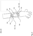
- FIG. 1 a schematic illustration of alternative embodiments of a system 100 comprising a neurostimulation device 110 in form of a nerve cuff is shown.
- a neurostimulation device 110 in form of a nerve cuff is illustrated.
- the neurostimulation device 110 comprises a first recording means 130 and a second recording means 140.
- the first and second recording means 130; 140 are arranged in a recording means distance 120 from each other.
- the first recording means 130 is provided with two recording elements 132; 134 being arranged in a first pattern 136.
- the recording elements 132; 134 of the first recording means 130 are arranged in a first recording element distance 138 from each other.
- the second recording means 140 is provided with two recording elements 142; 144 being arranged in a second pattern 146.
- the recording elements 142; 144 of the second recording means 140 are arranged in a second recording element distance 148 from each other.
- the first recording element distance 138 differs from the second recording element distance 148.
- the second recording element distance 148 is larger than the first recording element distance 138.
- the recording elements 132; 134; 142; 144 can be provided in form of at least one coil (upper illustration of Fig. 1 ) or in form of at least one electrode (lower illustration of Fig. 1 ) respectively.
- the recording elements 132; 134; 142; 144 can each be formed as one coil.
- each recording element 132; 134; 142; 144 can be provided in form of multiple electrodes, as shown in Fig. 1 .
- each recording element 132; 134; 142; 144 can be provided and distributed along the circumference of the neurostimulation device 110 in form of a nerve cuff, according to Fig. 1 .
- the material for the electrodes can be at least partially graphene, especially reduced graphene oxide (RGO).
- RGO reduced graphene oxide
- the electrode device has at least one electrode comprising graphene, in particular being made of graphene or a graphene-based material or comprising a graphene (based) coating.
- graphene (based) materials may be used in the context of the present invention, like e.g. reduced graphene oxide (rGO), graphene oxide, chemical vapour deposited graphene (CVD Graphene) or any other potential form of graphene.
- rGO reduced graphene oxide
- CVD Graphene chemical vapour deposited graphene
- such graphene based materials can provide improved electrical and mechanical properties, e.g. a beneficial flexibility of the resulting electrode.
- Such graphene electrodes particularly provide higher safe charge injection capacity as well as the signal-to-noise ratio/performance can be improved. Thereby, the electrode size can be reduced, even if the same amount of electrodes is maintained.
- the cross-sectional area of the at least one electrode can be reduced.
- graphene-based electrodes can provide for a safe electrical interface in aqueous environments, like in the context of neuromodulation of nervous tissue.
- the recording elements 132; 134; 142; 144 of the first and second recording means 130; 140 the first pattern 136 and the second pattern 146 is formed.
- FIG. 2 a schematic illustration of alternative embodiments of a system 100 comprising a neurostimulation device 110 in form of a skin patch, in particular for PNS applications, is shown.
- the neurostimulation device 110 is provided with a first recording means 130 and a second recording means 140 being separated from each other by a recording means distance 120 along the extension of the neurostimulation device 110.
- the recording elements 132; 134 of the first recording means 130 are arranged in a first pattern 136, wherein the recording elements 142; 144 of the second recording means 140 are arranged in a second pattern 146.
- the neurostimulation device 110 in form of a skin patch may be provided with a rectangular shape, as shown in Fig. 2 , in order to allow for an increased recording means distance 120 between the first and second recordings means 130; 140.
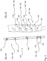
- FIG. 3 a schematic illustration of alternative embodiments of a system comprising a neurostimulation device 110 in form of a percutaneous device (left illustration of Fig. 3 ) and in form of a paddle device (right illustration of Fig. 3 ) are shown.
- the percutaneous neurostimulation device 110 may be formed in a strip-like manner (left illustration of Fig. 3 ).
- the neurostimulation devices 110 can be provided in any geometry and form being applicable and suitable for PNS.
- the neurostimulation device 110 comprises the first recording means 130 and the second recording means 140.
- the first and second recording means 130; 140 are arranged in the recording means distance 120 from each other.
- the first recording means 130 is provided with two recording elements 132; 134 being arranged in the first pattern 136.
- the recording elements 132; 134 of the first recording means 130 are arranged in the first recording element distance 138 from each other.
- the second recording means 140 is provided with two recording elements 142; 144 being arranged in the second pattern 146.
- the recording elements 142; 144 of the second recording means 140 are arranged in the second recording element distance 148 from each other.
- the recording elements 132; 134; 142; 144 can be provided in form of at least one electrode respectively.
- the recording elements 132; 134; 142; 144 may be provided in form of coils.
- the recording elements 132; 134; 142; 144 of the first and second recording means 130; 140 the first pattern 136 and the second pattern 146 are provided/formed.
- electrodes/coils can be distributed along the circumference/extension of a neurostimulation device 110 in order to form the recording elements 132; 134; 142; 144 respectively.
- FIG. 3 shows the embodiment of a percutaneous device 110 with an additional stimulation means 150 (left illustration of Fig. 2 ) as well as an embodiment (right illustration of Fig. 2 ) which is particularly formed for the purpose of NCV measurement, thus without an additional stimulation means 150.
- the stimulation means 150 can be provided inbetween the recoding means distance 120 of the neurostimulation device 110, thus between the first and second recording means 130; 140.
- the stimulation means 150 is provided in the same form as the recording elements 132; 134; 142; 144, thus in form of an electrode.
- the stimulation means 150 can be provided in form of at least one coil.
- the recording elements 132; 134; 142; 144 are provided e.g. as coils, while the stimulation means 150 is provided in form of an electrode.
- the at least one stimulation means 150 can be arranged at another location of the stimulation device 110 as well, e.g. at a top or bottom of the neurostimulation device 110 .
- Fig. 3 in form of a paddle device 110 (right illustration of Fig. 3 ) particularly shows an implementation with multiple first and second recording means 130; 140.
- first and second recording means 130; 140 may be arranged multiple times and in an alternating manner.
- the determination of a propagation of a nerve stimulus along the extension of the neurostimulation device 110 of the system 100 can be further enhanced.
- first pattern 138 of the first recording means 130 and the second pattern 148 of the second recording means 140 may provide a common and/or homogenous pattern of recording elements 132; 134; 142; 144, in particular of repetitively arranged recording elements 132; 134; 142; 144.
- FIG. 4 and Fig. 5 a schematic illustration of alternative embodiments concerning the measurement principle as applicable by embodiments according to Fig. 1 and/or Fig. 2 and/or Fig. 3 are shown.
- the function of the system 100 having a neurostimulation device 110 as exemplarily shown in Fig. 1 to Fig. 3 , can be described as follows.
- a stimulus/nerve pulse is propagated along a nerve structure/fiber 200.
- the first and second recording means 130; 140 are arranged, e.g. in form of coils being provided on a nerve cuff-like neurostimulation device 110 of the system 100.
- the first and second recording means 130; 140 are separated from each other by the recording means distance 120.
- the first recording means 130 forms a first pattern 136 with two recording elements 132; 134 being separated by the first recording element distance 138.
- the second recording means 140 form the second pattern 146 with two recording elements 142; 144 being separated by the second recording element distance 148.
- a recording signal is provided, indicating an intensity peak over the time(-line), as illustrated at the lower diagram of Fig. 4 .
- all recording elements 132; 134; 142; 144 can be connected to e.g. a control unit of the system 100 via a common signal line.
- the recording signals of the several recording elements 132; 134; 142; 144 can preferably be combined to a common recording signal 160, as shown in Fig. 4 .
- the natural nerve stimulus or an induced nerve stimulus propagates further along the nerve fiber 200, it is detected/determined/measured by each of the recording elements 132; 134; 142; 144 of the first and second recording means 130; 140.
- the resulting common recording signal 160 indicates four intensity peaks over the time(line), each being provided/determined by one of the corresponding recording elements 132; 134; 142; 144.
- the height of the intensity peak in the corresponding diagram of the common recording signal depends on the (recording) sensitivity of the respective recording elements 132; 134; 142; 144.
- the configuration of the neurostimulation device 110 e.g. with respect to the recording means distance 120 as well as the first/second recording elements distances 138; 148, is reflected and can be gathered from the diagram visualizing the common recording signal 160.
- the recording means distance 120 can describe the distance between the beginning of the first recording means 130 to the beginning of the second recording means 140.
- the recording elements 132; 134; 142; 144 are identically configured, in particular comprise the same sensitivity properties. This can particularly be gathered form the equal height of the peaks of the common recording signal 160.
- each of the recording elements 132; 134; 142; 144 can have a different sensitivity which can cause different peak heights within the common recording signal 160.
- the recording elements of a recording means 130; 140 can have same or different sensitivities, providing a sensitivity profile, i.e. a signature, for each recording means 130; 140.
- the difference between the first recording means 130 and the second recording means 140 according to Fig. 4 is the distance between the respective recording elements 132; 134; 142; 144, hence a deviation between the first recording element distance 138 and the second recording element distance 148.
- the first pattern 136 and the second pattern 146 differ from each other with regard to the first/second recording element distance 138; 148.
- FIG. 5 an embodiment according to Fig. 1 to Fig. 2 is shown, in particular with a stimulation means 150 as shown in Fig. 3 .
- the stimulation means 150 is situated between the first and second recording means 130; 140.
- the stimulation means 150 can induce a nerve stimulation in order to initiate a propagating stimulus along the nerve 200.
- the arrangement of the stimulation means 150 in Fig. 5 provides a first stimulation means distance 152 and a second stimulation means distance 154.
- the common recording signal 160 can indicate the propagation of the stimulus along the nerve 200 over the time, in particular subsequent to a signal processing by the control unit.
- a natural nerve stimulus or an induced nerve stimulus, i.e. provided via the stimulation means 150, propagating along a nerve 200 can be determined via the neurostimulation device 110.
- NCV measurement and signal (post-)processing particularly in the context of such miniaturized systems 100, can be simplified by utilizing first and second recording means 130; 140 being situated/arranged within a (pre-defined) recording means distance 120.
- the wiring of the neurostimulation device 110 can be simplified and the size of the system 100, in particular of the neurostimulation device 110, can be reduced, as well as a single common recording signal 160 can be provided for further processing.
Landscapes
- Health & Medical Sciences (AREA)
- Life Sciences & Earth Sciences (AREA)
- Engineering & Computer Science (AREA)
- General Health & Medical Sciences (AREA)
- Animal Behavior & Ethology (AREA)
- Veterinary Medicine (AREA)
- Biomedical Technology (AREA)
- Public Health (AREA)
- Nuclear Medicine, Radiotherapy & Molecular Imaging (AREA)
- Radiology & Medical Imaging (AREA)
- Neurosurgery (AREA)
- Neurology (AREA)
- Heart & Thoracic Surgery (AREA)
- Biophysics (AREA)
- Psychology (AREA)
- Cardiology (AREA)
- Physics & Mathematics (AREA)
- Medical Informatics (AREA)
- Molecular Biology (AREA)
- Pathology (AREA)
- Surgery (AREA)
- Physiology (AREA)
- Orthopedic Medicine & Surgery (AREA)
- Human Computer Interaction (AREA)
- Electrotherapy Devices (AREA)
- Measurement And Recording Of Electrical Phenomena And Electrical Characteristics Of The Living Body (AREA)
- Carbon And Carbon Compounds (AREA)
Claims (8)
- System (100) zur peripheren Nervenstimulation, insbesondere zum Erfassen und/oder zum Überwachen einer neuronalen Aktivität und/oder Muskelaktivität, das mindestens eine Neurostimulationsvorrichtung (110) aufweist,wobei die Neurostimulationsvorrichtung (110) mindestens eine erste Aufzeichnungseinrichtung (130) und eine zweite Aufzeichnungseinrichtung (140) aufweist,wobei die erste Aufzeichnungseinrichtung (130) und die zweite Aufzeichnungseinrichtung (140) dafür ausgelegt sind, unter einer Aufzeichnungseinrichtungsdistanz (120) zueinander angeordnet zu sein, und jeweils dafür ausgelegt sind, einen Stimulus zu erfassen, der sich entlang einer Nervenstruktur, insbesondere entlang eines efferenten Nervs und/oder eines afferenten Nervs, ausbreitet, so dass eine Geschwindigkeit des sich entlang der Nervenstruktur ausbreitenden Stimulus bestimmt werden kann,wobei die erste und die zweite Aufzeichnungseinrichtung (130; 140) jeweils mindestens zwei Aufzeichnungselemente (132; 134; 142; 144) aufweisen,wobei die Aufzeichnungselemente (132; 134) der ersten Aufzeichnungseinrichtung (130) in einem ersten Muster (136) angeordnet sind,wobei die Aufzeichnungselemente (142; 144) der zweiten Aufzeichnungseinrichtung (140) in einem zweiten Muster (146) angeordnet sind, das sich vom ersten Muster (136) unterscheidet.
- System (100) nach Anspruch 1,
dadurch gekennzeichnet, dass
das erste Muster (136) eine erste Aufzeichnungselementdistanz (138) zwischen den Aufzeichnungselementen (132; 134) des ersten Aufzeichnungselements (130) und das zweite Muster (146) eine zweite Aufzeichnungselementdistanz (148) zwischen den Aufzeichnungselementen (142; 144) der zweiten Aufzeichnungseinrichtung (140) aufweist. - System (100) nach Anspruch 2,
dadurch gekennzeichnet, dass
die erste Aufzeichnungselementdistanz (138) und die zweite Aufzeichnungselementdistanz (148) identisch sind oder voneinander abweichen. - System (100) nach einem der Ansprüche 1 bis 3,
dadurch gekennzeichnet, dass
jedes Aufzeichnungselement (132; 134; 142; 144) in Form von mindestens einer Elektrode oder Spule vorgesehen ist. - System (100) nach einem der vorhergehenden Ansprüche,
dadurch gekennzeichnet, dass
die Neurostimulationsvorrichtung (110) mindestens eine Stimulationseinrichtung (150) zum Übertragen von Stimulationssignalen auf ein Gewebe eines Patienten aufweist, um eine neuronale Stimulation und/oder Muskelstimulation zu initiieren, die vorzugsweise in Form von mindestens einer Elektrode oder Spule ausgelegt ist. - System (100) nach einem der vorhergehenden Ansprüche,
dadurch gekennzeichnet, dass
die erste Aufzeichnungseinrichtung (130) und die zweite Aufzeichnungseinrichtung (140), insbesondere die Aufzeichnungselemente (132; 134) der ersten Aufzeichnungseinrichtung (130) und die Aufzeichnungselemente (142; 144) der zweiten Aufzeichnungseinrichtung (140), unterschiedliche Aufzeichnungsempfindlichkeiten aufweisen. - System (100) nach einem der vorhergehenden Ansprüche,
dadurch gekennzeichnet, dass
das System darüber hinaus eine Steuereinheit aufweist, die dafür ausgelegt ist, die Neurostimulationsvorrichtung (110) zu betreiben, insbesondere deren Betrieb zu steuern und/oder zu regeln, und/oder eine Signalverarbeitung der Signale, wie sie von der ersten und zweiten Aufzeichnungseinrichtung (130; 140) empfangen werden, bereitzustellen. - System (100) nach einem der vorhergehenden Ansprüche,
dadurch gekennzeichnet, dass
ein Aufzeichnungssignal von der ersten und/oder zweiten Aufzeichnungseinrichtung (130; 140), insbesondere der Aufzeichnungselemente (132; 134; 142; 144) der ersten und/oder zweiten Aufzeichnungseinrichtung (130; 140), über eine gemeinsame Signalverbindung vorzugsweise an eine Steuereinheit des Systems (100) weitergeleitet wird.
Applications Claiming Priority (2)
| Application Number | Priority Date | Filing Date | Title |
|---|---|---|---|
| EP21382525 | 2021-06-11 | ||
| PCT/EP2022/065879 WO2022258824A1 (en) | 2021-06-11 | 2022-06-10 | System for peripheral nerve stimulation |
Publications (2)
| Publication Number | Publication Date |
|---|---|
| EP4351704A1 EP4351704A1 (de) | 2024-04-17 |
| EP4351704B1 true EP4351704B1 (de) | 2025-05-28 |
Family
ID=77071437
Family Applications (6)
| Application Number | Title | Priority Date | Filing Date |
|---|---|---|---|
| EP21814797.3A Pending EP4351701A1 (de) | 2021-06-11 | 2021-11-24 | Neurale schnittstelle mit kantengeschütztem porösem material |
| EP21814796.5A Pending EP4351700A1 (de) | 2021-06-11 | 2021-11-24 | Verankerte elektrodensysteme zur langfristigen neurostimulation |
| EP22732267.4A Active EP4351704B1 (de) | 2021-06-11 | 2022-06-10 | System zur peripheren nervenstimulation |
| EP22732265.8A Active EP4351702B1 (de) | 2021-06-11 | 2022-06-10 | Elektrodenvorrichtung |
| EP22732268.2A Pending EP4351705A1 (de) | 2021-06-11 | 2022-06-10 | System für neurostimulationsanwendungen |
| EP22732266.6A Pending EP4351703A1 (de) | 2021-06-11 | 2022-06-10 | System für neuromodulationsanwendungen |
Family Applications Before (2)
| Application Number | Title | Priority Date | Filing Date |
|---|---|---|---|
| EP21814797.3A Pending EP4351701A1 (de) | 2021-06-11 | 2021-11-24 | Neurale schnittstelle mit kantengeschütztem porösem material |
| EP21814796.5A Pending EP4351700A1 (de) | 2021-06-11 | 2021-11-24 | Verankerte elektrodensysteme zur langfristigen neurostimulation |
Family Applications After (3)
| Application Number | Title | Priority Date | Filing Date |
|---|---|---|---|
| EP22732265.8A Active EP4351702B1 (de) | 2021-06-11 | 2022-06-10 | Elektrodenvorrichtung |
| EP22732268.2A Pending EP4351705A1 (de) | 2021-06-11 | 2022-06-10 | System für neurostimulationsanwendungen |
| EP22732266.6A Pending EP4351703A1 (de) | 2021-06-11 | 2022-06-10 | System für neuromodulationsanwendungen |
Country Status (6)
| Country | Link |
|---|---|
| US (6) | US20240285938A1 (de) |
| EP (6) | EP4351701A1 (de) |
| JP (2) | JP2024521228A (de) |
| CN (2) | CN117479978A (de) |
| ES (1) | ES3039012T3 (de) |
| WO (8) | WO2022258211A1 (de) |
Families Citing this family (4)
| Publication number | Priority date | Publication date | Assignee | Title |
|---|---|---|---|---|
| WO2025061735A1 (en) * | 2023-09-18 | 2025-03-27 | Inbrain Neuroelectronics Sl | Neuromodulation system |
| WO2025207669A1 (en) * | 2024-03-26 | 2025-10-02 | The Alfred E. Mann Foundation For Scientific Research | Vagus nerve stimulation systems and methods |
| CN118384413B (zh) * | 2024-04-24 | 2024-11-19 | 苏州科技大学 | 一种类骨松质空间微结构神经电极及其制备方法 |
| WO2026008703A1 (en) | 2024-07-04 | 2026-01-08 | Borealis Gmbh | Layered polyethylene mdo film with improved adhesion |
Family Cites Families (49)
| Publication number | Priority date | Publication date | Assignee | Title |
|---|---|---|---|---|
| DE59712479D1 (de) * | 1996-03-21 | 2005-12-22 | Biotronik Gmbh & Co Kg | Implantierbare Stimulationselektrode |
| US6148233A (en) * | 1997-03-07 | 2000-11-14 | Cardiac Science, Inc. | Defibrillation system having segmented electrodes |
| US9320900B2 (en) * | 1998-08-05 | 2016-04-26 | Cyberonics, Inc. | Methods and systems for determining subject-specific parameters for a neuromodulation therapy |
| WO2001038958A1 (en) * | 1999-11-24 | 2001-05-31 | Center For Advanced Science And Technology Incubation, Ltd. | Method and device for stimulating tactile sensation by electricity |
| US7212867B2 (en) | 2000-12-07 | 2007-05-01 | Medtronic, Inc. | Directional brain stimulation and recording leads |
| US7142909B2 (en) | 2002-04-11 | 2006-11-28 | Second Sight Medical Products, Inc. | Biocompatible bonding method and electronics package suitable for implantation |
| US7162308B2 (en) * | 2002-11-26 | 2007-01-09 | Wilson Greatbatch Technologies, Inc. | Nanotube coatings for implantable electrodes |
| US20070129771A1 (en) * | 2005-04-20 | 2007-06-07 | Kurtz Ronald L | Device, method and stimulus unit for testing neuromuscular function |
| US7822482B2 (en) | 2005-07-29 | 2010-10-26 | Medtronic, Inc. | Electrical stimulation lead with rounded array of electrodes |
| EP1931419B1 (de) | 2005-10-07 | 2016-08-10 | NeuroNexus Technologies, Inc. | Modulares mehrkanal-mikroelektrodenarray |
| US20070128420A1 (en) * | 2005-12-07 | 2007-06-07 | Mariam Maghribi | Hybrid composite for biological tissue interface devices |
| US20100114272A1 (en) * | 2006-12-07 | 2010-05-06 | Sebastian Haidarliu | Multiple micro-wire electrode device and methods |
| US20090204173A1 (en) * | 2007-11-05 | 2009-08-13 | Zi-Ping Fang | Multi-Frequency Neural Treatments and Associated Systems and Methods |
| JP2010099415A (ja) * | 2008-10-27 | 2010-05-06 | Olympus Corp | 心臓治療装置 |
| EP2783727B1 (de) | 2008-11-12 | 2016-11-09 | Ecole Polytechnique Fédérale de Lausanne | Mikrohergestellte Neurostimulationsvorrichtung |
| US8561292B2 (en) | 2008-11-14 | 2013-10-22 | The Regents Of The University Of Michigan | Method for manufacturing an implantable electronic device |
| US8250755B2 (en) * | 2009-04-24 | 2012-08-28 | Advanced Neuromodulation Systems, Inc. | Process for fabricating a medical lead |
| US8046909B2 (en) | 2009-04-24 | 2011-11-01 | Advanced Neuromodulation Systems, Inc. | Method of fabricating stimulation lead |
| US20110077699A1 (en) * | 2009-09-30 | 2011-03-31 | John Swanson | Medical leads with segmented electrodes and methods of fabrication thereof |
| US8774891B1 (en) * | 2009-11-16 | 2014-07-08 | Pmt Corporation | Cortical electrode assemblies |
| WO2011115643A1 (en) * | 2010-03-17 | 2011-09-22 | The Board Of Trustees Of The University Of Illinois | Implantable biomedical devices on bioresorbable substrates |
| CA2825550C (en) * | 2011-03-24 | 2022-07-12 | California Institute Of Technology | Neurostimulator |
| WO2013067018A2 (en) * | 2011-11-01 | 2013-05-10 | Synthes Usa, Llc | Intraoperative neurophysiological monitoring system |
| JP6009343B2 (ja) * | 2011-12-26 | 2016-10-19 | 株式会社半導体エネルギー研究所 | 二次電池用正極および二次電池用正極の作製方法 |
| US9827413B2 (en) | 2012-04-17 | 2017-11-28 | Boston Scientific Neuromodulation Corporation | Lead construction for deep brain stimulation |
| US8843209B2 (en) * | 2012-04-27 | 2014-09-23 | Medtronic, Inc. | Ramping parameter values for electrical stimulation therapy |
| GB201219417D0 (en) * | 2012-10-29 | 2012-12-12 | Univ Ulster | Coatings |
| US11224372B2 (en) * | 2014-01-07 | 2022-01-18 | The Trustees Of The University Of Pennsylvania | Graphene-passivated implantable electrodes |
| US10123731B2 (en) * | 2014-08-08 | 2018-11-13 | Medtronic Xomed, Inc. | Wireless sensors for nerve integrity monitoring systems |
| US9474894B2 (en) | 2014-08-27 | 2016-10-25 | Aleva Neurotherapeutics | Deep brain stimulation lead |
| US20160120472A1 (en) * | 2014-10-31 | 2016-05-05 | The Government Of The United States Of America, As Represented By The Secretary Of The Navy | Low Dissolution Rate Device and Method |
| US9364659B1 (en) | 2015-04-27 | 2016-06-14 | Dantam K. Rao | Smart lead for deep brain stimulation |
| US20180243550A1 (en) * | 2015-08-26 | 2018-08-30 | Vomaris Innovations, Inc. | Methods and devices for tissue treatment |
| US10155107B2 (en) * | 2015-10-07 | 2018-12-18 | Medtronic, Inc. | Implantable modular electrode array assembly |
| US20210187161A1 (en) * | 2016-04-14 | 2021-06-24 | Massachusetts Eye And Ear Infirmary | Medical device comprising graphene coating |
| CN109804331B (zh) * | 2016-12-02 | 2021-06-22 | 皮松科技股份有限公司 | 检测和使用身体组织电信号 |
| CN106823136A (zh) * | 2016-12-30 | 2017-06-13 | 北京工业大学 | 一种产生新型刺激波形的耳迷走神经刺激系统 |
| AU2018215194B2 (en) * | 2017-02-01 | 2023-02-02 | The Alfred E. Mann Foundation For Scientific Research | Stimulator systems and methods for obstructive sleep apnea |
| US10900924B2 (en) * | 2017-06-19 | 2021-01-26 | International Business Machines Corporation | Porous nanostructured electrodes for detection of neurotransmitters |
| KR102173025B1 (ko) * | 2018-01-22 | 2020-11-02 | 주식회사 지브레인 | 전기 요법용 그래핀 바이오 소자 |
| US10780270B2 (en) * | 2018-03-15 | 2020-09-22 | Avent, Inc. | System and method to percutaneously block painful sensations |
| US11298538B2 (en) * | 2018-06-29 | 2022-04-12 | Boston Scientific Neuromodulation Corporation | Neuromodulation calibration based on neurophysiological signals |
| JP7119718B2 (ja) * | 2018-07-30 | 2022-08-17 | オムロンヘルスケア株式会社 | 端末装置、電気治療器、および治療システム |
| WO2020087123A1 (en) * | 2018-10-30 | 2020-05-07 | Saluda Medical Pty Ltd | Automated neural conduction velocity estimation |
| US11167128B2 (en) * | 2018-11-16 | 2021-11-09 | Boston Scientific Neuromodulation Corporation | Directional electrical stimulation leads, systems and methods for spinal cord stimulation |
| WO2020128749A1 (en) * | 2018-12-21 | 2020-06-25 | Galvani Bioelectronics Limited | Implantable neurostimulation system |
| EP3958962A1 (de) * | 2019-07-26 | 2022-03-02 | Boston Scientific Neuromodulation Corporation | Verfahren und systeme zur herstellung von elektrischen stimulationsanpassungen basierend auf patientenspezifischen faktoren |
| FI128967B (en) * | 2020-01-21 | 2021-04-15 | Teknologian Tutkimuskeskus Vtt Oy | Dry electrode for biometric measurement of the skin and its manufacturing method |
| US20210236824A1 (en) * | 2020-02-05 | 2021-08-05 | Duke University | Systems and methods for eliminating onset response in nerve conduction block |
-
2021
- 2021-11-24 US US18/569,158 patent/US20240285938A1/en active Pending
- 2021-11-24 US US18/567,731 patent/US20240269460A1/en active Pending
- 2021-11-24 EP EP21814797.3A patent/EP4351701A1/de active Pending
- 2021-11-24 WO PCT/EP2021/082726 patent/WO2022258211A1/en not_active Ceased
- 2021-11-24 EP EP21814796.5A patent/EP4351700A1/de active Pending
- 2021-11-24 WO PCT/EP2021/082838 patent/WO2022258212A1/en not_active Ceased
- 2021-11-24 WO PCT/EP2021/082725 patent/WO2022258210A1/en not_active Ceased
-
2022
- 2022-06-10 EP EP22732267.4A patent/EP4351704B1/de active Active
- 2022-06-10 WO PCT/EP2022/065868 patent/WO2022258820A1/en not_active Ceased
- 2022-06-10 EP EP22732265.8A patent/EP4351702B1/de active Active
- 2022-06-10 CN CN202280041722.4A patent/CN117479978A/zh active Pending
- 2022-06-10 US US18/566,964 patent/US20240261568A1/en active Pending
- 2022-06-10 US US18/568,653 patent/US20240285962A1/en active Pending
- 2022-06-10 ES ES22732267T patent/ES3039012T3/es active Active
- 2022-06-10 US US18/568,703 patent/US20240269466A1/en active Pending
- 2022-06-10 EP EP22732268.2A patent/EP4351705A1/de active Pending
- 2022-06-10 CN CN202280041721.XA patent/CN117479977A/zh active Pending
- 2022-06-10 WO PCT/EP2022/065879 patent/WO2022258824A1/en not_active Ceased
- 2022-06-10 WO PCT/EP2022/065882 patent/WO2022258826A1/en not_active Ceased
- 2022-06-10 JP JP2023576222A patent/JP2024521228A/ja active Pending
- 2022-06-10 WO PCT/EP2022/065863 patent/WO2022258818A1/en not_active Ceased
- 2022-06-10 EP EP22732266.6A patent/EP4351703A1/de active Pending
- 2022-06-10 US US18/567,741 patent/US20240207618A1/en active Pending
- 2022-06-10 WO PCT/EP2022/065854 patent/WO2022258816A1/en not_active Ceased
- 2022-06-10 JP JP2023576160A patent/JP2024520848A/ja active Pending
Also Published As
| Publication number | Publication date |
|---|---|
| EP4351704A1 (de) | 2024-04-17 |
| WO2022258818A1 (en) | 2022-12-15 |
| CN117479977A (zh) | 2024-01-30 |
| WO2022258826A1 (en) | 2022-12-15 |
| EP4351701A1 (de) | 2024-04-17 |
| EP4351702C0 (de) | 2025-12-17 |
| US20240269466A1 (en) | 2024-08-15 |
| US20240269460A1 (en) | 2024-08-15 |
| WO2022258816A1 (en) | 2022-12-15 |
| US20240285938A1 (en) | 2024-08-29 |
| WO2022258820A1 (en) | 2022-12-15 |
| EP4351700A1 (de) | 2024-04-17 |
| WO2022258211A1 (en) | 2022-12-15 |
| WO2022258824A1 (en) | 2022-12-15 |
| JP2024521228A (ja) | 2024-05-28 |
| US20240285962A1 (en) | 2024-08-29 |
| WO2022258210A1 (en) | 2022-12-15 |
| US20240261568A1 (en) | 2024-08-08 |
| CN117479978A (zh) | 2024-01-30 |
| EP4351702B1 (de) | 2025-12-17 |
| EP4351705A1 (de) | 2024-04-17 |
| WO2022258212A1 (en) | 2022-12-15 |
| ES3039012T3 (en) | 2025-10-16 |
| EP4351702A1 (de) | 2024-04-17 |
| JP2024520848A (ja) | 2024-05-24 |
| US20240207618A1 (en) | 2024-06-27 |
| EP4351703A1 (de) | 2024-04-17 |
Similar Documents
| Publication | Publication Date | Title |
|---|---|---|
| EP4351704B1 (de) | System zur peripheren nervenstimulation | |
| US12208268B2 (en) | Systems, devices, and methods for electrical stimulation using feedback to adjust stimulation parameters | |
| US10849525B2 (en) | Monitoring brain neural activity | |
| CN107530543B (zh) | 电极到神经距离估计 | |
| CN106419891B (zh) | 用于腓肠神经传导速度和振幅的自动化测量的装置和方法 | |
| EP3122247B1 (de) | Beurteilung des neutralen zustands aus aktionspotential | |
| US8543221B2 (en) | External systems for detecting implantable neurostimulation leads and devices, and methods of using same | |
| US12357836B2 (en) | User interface for neural signal and biomarker visualization and assessment | |
| US20050182456A1 (en) | Automated cortical mapping | |
| CN104470420B (zh) | 用于对母体心率的改进的确定的方法和其中的胎儿监测系统 | |
| US20130030319A1 (en) | Cardiac monitoring using spinal cord stimulation electrodes | |
| US20130123600A1 (en) | Multimodal Brain Sensing Lead | |
| US20140039312A1 (en) | Pacing-site selection for lead placement | |
| EP2135549A1 (de) | Nachtatmungsrate zur Herzfehlerüberwachung | |
| US12508421B2 (en) | System and method for monitoring response to neuromodulation | |
| JP2005528138A (ja) | 脳刺激、特に深部脳刺激のために電極を目標点に位置決めする装置 | |
| KR20130134417A (ko) | 경혈의 센싱 및 위치 추적장치 | |
| JP7377801B2 (ja) | 神経刺激およびインピーダンス測定のための神経インターフェースデバイス | |
| CN109937003B (zh) | 用于放置脊髓刺激器引线的系统和方法 | |
| CN110869082B (zh) | 评估响应于迷走神经刺激的自主参与的庞加莱显示 | |
| US20240198111A1 (en) | Apparatus, a system and a method for stimulating a part of a peripheral nervous system | |
| US20260041915A1 (en) | Systems, apparatuses, and methods for facilitating electrode placement for spinal cord stimulation | |
| WO2025114722A1 (en) | Closed-loop neuromodulation device and control method | |
| CN118251174A (zh) | 从心电图估计血清钾和/或肾小球滤过率以用于心力衰竭患者管理 | |
| Galán et al. | Pre-synaptic modulation of afferent feedback in the macaque spinal cord does not modulate with cycles of peripheral oscillations around 10 Hz |
Legal Events
| Date | Code | Title | Description |
|---|---|---|---|
| STAA | Information on the status of an ep patent application or granted ep patent |
Free format text: STATUS: UNKNOWN |
|
| STAA | Information on the status of an ep patent application or granted ep patent |
Free format text: STATUS: THE INTERNATIONAL PUBLICATION HAS BEEN MADE |
|
| PUAI | Public reference made under article 153(3) epc to a published international application that has entered the european phase |
Free format text: ORIGINAL CODE: 0009012 |
|
| STAA | Information on the status of an ep patent application or granted ep patent |
Free format text: STATUS: REQUEST FOR EXAMINATION WAS MADE |
|
| 17P | Request for examination filed |
Effective date: 20231216 |
|
| AK | Designated contracting states |
Kind code of ref document: A1 Designated state(s): AL AT BE BG CH CY CZ DE DK EE ES FI FR GB GR HR HU IE IS IT LI LT LU LV MC MK MT NL NO PL PT RO RS SE SI SK SM TR |
|
| DAV | Request for validation of the european patent (deleted) | ||
| DAX | Request for extension of the european patent (deleted) | ||
| GRAP | Despatch of communication of intention to grant a patent |
Free format text: ORIGINAL CODE: EPIDOSNIGR1 |
|
| STAA | Information on the status of an ep patent application or granted ep patent |
Free format text: STATUS: GRANT OF PATENT IS INTENDED |
|
| RIC1 | Information provided on ipc code assigned before grant |
Ipc: A61B 5/293 20210101ALI20241231BHEP Ipc: A61B 5/263 20210101ALI20241231BHEP Ipc: A61N 1/375 20060101ALI20241231BHEP Ipc: A61N 1/36 20060101ALI20241231BHEP Ipc: A61N 1/05 20060101AFI20241231BHEP |
|
| INTG | Intention to grant announced |
Effective date: 20250115 |
|
| GRAS | Grant fee paid |
Free format text: ORIGINAL CODE: EPIDOSNIGR3 |
|
| GRAA | (expected) grant |
Free format text: ORIGINAL CODE: 0009210 |
|
| STAA | Information on the status of an ep patent application or granted ep patent |
Free format text: STATUS: THE PATENT HAS BEEN GRANTED |
|
| AK | Designated contracting states |
Kind code of ref document: B1 Designated state(s): AL AT BE BG CH CY CZ DE DK EE ES FI FR GB GR HR HU IE IS IT LI LT LU LV MC MK MT NL NO PL PT RO RS SE SI SK SM TR |
|
| REG | Reference to a national code |
Ref country code: GB Ref legal event code: FG4D |
|
| REG | Reference to a national code |
Ref country code: CH Ref legal event code: EP |
|
| REG | Reference to a national code |
Ref country code: IE Ref legal event code: FG4D Ref country code: DE Ref legal event code: R096 Ref document number: 602022015232 Country of ref document: DE |
|
| P01 | Opt-out of the competence of the unified patent court (upc) registered |
Free format text: CASE NUMBER: APP_26459/2025 Effective date: 20250604 |
|
| PGFP | Annual fee paid to national office [announced via postgrant information from national office to epo] |
Ref country code: AT Payment date: 20250721 Year of fee payment: 4 |
|
| PGFP | Annual fee paid to national office [announced via postgrant information from national office to epo] |
Ref country code: NL Payment date: 20250704 Year of fee payment: 4 |
|
| REG | Reference to a national code |
Ref country code: NL Ref legal event code: FP |
|
| PG25 | Lapsed in a contracting state [announced via postgrant information from national office to epo] |
Ref country code: FI Free format text: LAPSE BECAUSE OF FAILURE TO SUBMIT A TRANSLATION OF THE DESCRIPTION OR TO PAY THE FEE WITHIN THE PRESCRIBED TIME-LIMIT Effective date: 20250528 |
|
| PGFP | Annual fee paid to national office [announced via postgrant information from national office to epo] |
Ref country code: ES Payment date: 20250807 Year of fee payment: 4 |
|
| PGFP | Annual fee paid to national office [announced via postgrant information from national office to epo] |
Ref country code: DE Payment date: 20250707 Year of fee payment: 4 |
|
| REG | Reference to a national code |
Ref country code: LT Ref legal event code: MG9D |
|
| PG25 | Lapsed in a contracting state [announced via postgrant information from national office to epo] |
Ref country code: GR Free format text: LAPSE BECAUSE OF FAILURE TO SUBMIT A TRANSLATION OF THE DESCRIPTION OR TO PAY THE FEE WITHIN THE PRESCRIBED TIME-LIMIT Effective date: 20250829 Ref country code: NO Free format text: LAPSE BECAUSE OF FAILURE TO SUBMIT A TRANSLATION OF THE DESCRIPTION OR TO PAY THE FEE WITHIN THE PRESCRIBED TIME-LIMIT Effective date: 20250828 |
|
| PG25 | Lapsed in a contracting state [announced via postgrant information from national office to epo] |
Ref country code: PL Free format text: LAPSE BECAUSE OF FAILURE TO SUBMIT A TRANSLATION OF THE DESCRIPTION OR TO PAY THE FEE WITHIN THE PRESCRIBED TIME-LIMIT Effective date: 20250528 |
|
| PGFP | Annual fee paid to national office [announced via postgrant information from national office to epo] |
Ref country code: IT Payment date: 20250630 Year of fee payment: 4 |
|
| PG25 | Lapsed in a contracting state [announced via postgrant information from national office to epo] |
Ref country code: BG Free format text: LAPSE BECAUSE OF FAILURE TO SUBMIT A TRANSLATION OF THE DESCRIPTION OR TO PAY THE FEE WITHIN THE PRESCRIBED TIME-LIMIT Effective date: 20250528 |
|
| REG | Reference to a national code |
Ref country code: ES Ref legal event code: FG2A Ref document number: 3039012 Country of ref document: ES Kind code of ref document: T3 Effective date: 20251016 |
|
| PG25 | Lapsed in a contracting state [announced via postgrant information from national office to epo] |
Ref country code: HR Free format text: LAPSE BECAUSE OF FAILURE TO SUBMIT A TRANSLATION OF THE DESCRIPTION OR TO PAY THE FEE WITHIN THE PRESCRIBED TIME-LIMIT Effective date: 20250528 |
|
| PGFP | Annual fee paid to national office [announced via postgrant information from national office to epo] |
Ref country code: FR Payment date: 20250703 Year of fee payment: 4 |
|
| PGFP | Annual fee paid to national office [announced via postgrant information from national office to epo] |
Ref country code: CH Payment date: 20250814 Year of fee payment: 4 |
|
| PG25 | Lapsed in a contracting state [announced via postgrant information from national office to epo] |
Ref country code: RS Free format text: LAPSE BECAUSE OF FAILURE TO SUBMIT A TRANSLATION OF THE DESCRIPTION OR TO PAY THE FEE WITHIN THE PRESCRIBED TIME-LIMIT Effective date: 20250828 |
|
| PG25 | Lapsed in a contracting state [announced via postgrant information from national office to epo] |
Ref country code: IS Free format text: LAPSE BECAUSE OF FAILURE TO SUBMIT A TRANSLATION OF THE DESCRIPTION OR TO PAY THE FEE WITHIN THE PRESCRIBED TIME-LIMIT Effective date: 20250928 |
|
| PG25 | Lapsed in a contracting state [announced via postgrant information from national office to epo] |
Ref country code: LV Free format text: LAPSE BECAUSE OF FAILURE TO SUBMIT A TRANSLATION OF THE DESCRIPTION OR TO PAY THE FEE WITHIN THE PRESCRIBED TIME-LIMIT Effective date: 20250528 |
|
| REG | Reference to a national code |
Ref country code: AT Ref legal event code: MK05 Ref document number: 1798304 Country of ref document: AT Kind code of ref document: T Effective date: 20250528 |
|
| PG25 | Lapsed in a contracting state [announced via postgrant information from national office to epo] |
Ref country code: DK Free format text: LAPSE BECAUSE OF FAILURE TO SUBMIT A TRANSLATION OF THE DESCRIPTION OR TO PAY THE FEE WITHIN THE PRESCRIBED TIME-LIMIT Effective date: 20250528 Ref country code: AT Free format text: LAPSE BECAUSE OF FAILURE TO SUBMIT A TRANSLATION OF THE DESCRIPTION OR TO PAY THE FEE WITHIN THE PRESCRIBED TIME-LIMIT Effective date: 20250528 Ref country code: SM Free format text: LAPSE BECAUSE OF FAILURE TO SUBMIT A TRANSLATION OF THE DESCRIPTION OR TO PAY THE FEE WITHIN THE PRESCRIBED TIME-LIMIT Effective date: 20250528 |
|
| PG25 | Lapsed in a contracting state [announced via postgrant information from national office to epo] |
Ref country code: CZ Free format text: LAPSE BECAUSE OF FAILURE TO SUBMIT A TRANSLATION OF THE DESCRIPTION OR TO PAY THE FEE WITHIN THE PRESCRIBED TIME-LIMIT Effective date: 20250528 |
|
| PG25 | Lapsed in a contracting state [announced via postgrant information from national office to epo] |
Ref country code: EE Free format text: LAPSE BECAUSE OF FAILURE TO SUBMIT A TRANSLATION OF THE DESCRIPTION OR TO PAY THE FEE WITHIN THE PRESCRIBED TIME-LIMIT Effective date: 20250528 |
|
| PG25 | Lapsed in a contracting state [announced via postgrant information from national office to epo] |
Ref country code: SK Free format text: LAPSE BECAUSE OF FAILURE TO SUBMIT A TRANSLATION OF THE DESCRIPTION OR TO PAY THE FEE WITHIN THE PRESCRIBED TIME-LIMIT Effective date: 20250528 |