EP4351448B1 - Abwinkelbarer schaft für ein medizinisches handinstrument - Google Patents
Abwinkelbarer schaft für ein medizinisches handinstrument Download PDFInfo
- Publication number
- EP4351448B1 EP4351448B1 EP22757494.4A EP22757494A EP4351448B1 EP 4351448 B1 EP4351448 B1 EP 4351448B1 EP 22757494 A EP22757494 A EP 22757494A EP 4351448 B1 EP4351448 B1 EP 4351448B1
- Authority
- EP
- European Patent Office
- Prior art keywords
- shaft
- shaft section
- flexible
- distal
- section
- Prior art date
- Legal status (The legal status is an assumption and is not a legal conclusion. Google has not performed a legal analysis and makes no representation as to the accuracy of the status listed.)
- Active
Links
Images




Classifications
-
- A—HUMAN NECESSITIES
- A61—MEDICAL OR VETERINARY SCIENCE; HYGIENE
- A61B—DIAGNOSIS; SURGERY; IDENTIFICATION
- A61B17/00—Surgical instruments, devices or methods
- A61B17/28—Surgical forceps
- A61B17/29—Forceps for use in minimally invasive surgery
-
- A—HUMAN NECESSITIES
- A61—MEDICAL OR VETERINARY SCIENCE; HYGIENE
- A61B—DIAGNOSIS; SURGERY; IDENTIFICATION
- A61B1/00—Instruments for performing medical examinations of the interior of cavities or tubes of the body by visual or photographical inspection, e.g. endoscopes; Illuminating arrangements therefor
- A61B1/005—Flexible endoscopes
- A61B1/0051—Flexible endoscopes with controlled bending of insertion part
- A61B1/0057—Constructional details of force transmission elements, e.g. control wires
-
- A—HUMAN NECESSITIES
- A61—MEDICAL OR VETERINARY SCIENCE; HYGIENE
- A61B—DIAGNOSIS; SURGERY; IDENTIFICATION
- A61B1/00—Instruments for performing medical examinations of the interior of cavities or tubes of the body by visual or photographical inspection, e.g. endoscopes; Illuminating arrangements therefor
- A61B1/00112—Connection or coupling means
- A61B1/00121—Connectors, fasteners and adapters, e.g. on the endoscope handle
- A61B1/00128—Connectors, fasteners and adapters, e.g. on the endoscope handle mechanical, e.g. for tubes or pipes
-
- A—HUMAN NECESSITIES
- A61—MEDICAL OR VETERINARY SCIENCE; HYGIENE
- A61B—DIAGNOSIS; SURGERY; IDENTIFICATION
- A61B17/00—Surgical instruments, devices or methods
- A61B17/16—Instruments for performing osteoclasis; Drills or chisels for bones; Trepans
- A61B17/1613—Component parts
- A61B17/1633—Sleeves, i.e. non-rotating parts surrounding the bit shaft, e.g. the sleeve forming a single unit with the bit shaft
-
- A—HUMAN NECESSITIES
- A61—MEDICAL OR VETERINARY SCIENCE; HYGIENE
- A61B—DIAGNOSIS; SURGERY; IDENTIFICATION
- A61B17/00—Surgical instruments, devices or methods
- A61B17/32—Surgical cutting instruments
- A61B17/320016—Endoscopic cutting instruments, e.g. arthroscopes, resectoscopes
- A61B17/32002—Endoscopic cutting instruments, e.g. arthroscopes, resectoscopes with continuously rotating, oscillating or reciprocating cutting instruments
-
- A—HUMAN NECESSITIES
- A61—MEDICAL OR VETERINARY SCIENCE; HYGIENE
- A61B—DIAGNOSIS; SURGERY; IDENTIFICATION
- A61B17/00—Surgical instruments, devices or methods
- A61B17/16—Instruments for performing osteoclasis; Drills or chisels for bones; Trepans
- A61B17/1613—Component parts
- A61B17/1631—Special drive shafts, e.g. flexible shafts
-
- A—HUMAN NECESSITIES
- A61—MEDICAL OR VETERINARY SCIENCE; HYGIENE
- A61B—DIAGNOSIS; SURGERY; IDENTIFICATION
- A61B17/00—Surgical instruments, devices or methods
- A61B17/16—Instruments for performing osteoclasis; Drills or chisels for bones; Trepans
- A61B17/1662—Instruments for performing osteoclasis; Drills or chisels for bones; Trepans for particular parts of the body
- A61B17/1671—Instruments for performing osteoclasis; Drills or chisels for bones; Trepans for particular parts of the body for the spine
-
- A—HUMAN NECESSITIES
- A61—MEDICAL OR VETERINARY SCIENCE; HYGIENE
- A61B—DIAGNOSIS; SURGERY; IDENTIFICATION
- A61B17/00—Surgical instruments, devices or methods
- A61B17/28—Surgical forceps
- A61B17/29—Forceps for use in minimally invasive surgery
- A61B2017/2926—Details of heads or jaws
- A61B2017/2927—Details of heads or jaws the angular position of the head being adjustable with respect to the shaft
-
- A—HUMAN NECESSITIES
- A61—MEDICAL OR VETERINARY SCIENCE; HYGIENE
- A61B—DIAGNOSIS; SURGERY; IDENTIFICATION
- A61B17/00—Surgical instruments, devices or methods
- A61B17/32—Surgical cutting instruments
- A61B17/320016—Endoscopic cutting instruments, e.g. arthroscopes, resectoscopes
- A61B17/32002—Endoscopic cutting instruments, e.g. arthroscopes, resectoscopes with continuously rotating, oscillating or reciprocating cutting instruments
- A61B2017/320032—Details of the rotating or oscillating shaft, e.g. using a flexible shaft
Definitions
- the present disclosure relates to a shaft of or for a medical hand instrument.
- milling handpieces There are also already manufacturers of angled milling handpieces/medical hand instruments. These are mainly used for endoscopic procedures on the spine and enable minimally invasive techniques as well as easy processing of difficult-to-access structures in this area.
- the joint constructions of these milling handpieces have a rather open design and have a certain degree of flexibility in terms of angle. This means that when pressure is applied to the milling tip, the angle changes slightly.
- these milling handpieces only allow angles of up to 36°.
- One example of this is milling handpieces from Joimax.
- cordless screwdrivers with an inclined plane.
- cordless screwdrivers with an angled head have a similar swivel joint to the one described below and have a very good force absorption of the angle (rigid joint).
- angles of up to 90° are possible.
- the cordless screwdrivers have to be adjusted from the outside. They therefore do not have internal control.
- a handpiece can be chosen between three variants: 0°, 7.5° and 15° angles.
- the biggest disadvantage is the large bending radius used to achieve the angle. This takes up a lot of space and limits the options for action in the surgical field.
- the angle cannot be adjusted intraoperatively. Due to the fixed angle, endoscopic work with the angled shafts is not possible, as they cannot be inserted into the straight working channel of the endoscope. Furthermore, the maximum angle of 15° is not particularly large.
- a milling cutter with a distal and a proximal shaft section is known, which can be rotated relative to each other in such a way that the two shaft sections can be angled relative to each other by their inclined front sides.
- the two shaft sections are angled relative to each other by a bevel gear.
- the RU 2 181 566 C2 discloses a bendable hand instrument.
- a tubular intermediate section has a toothing at each end of the intermediate section.
- the toothing meshes with a corresponding toothing on a distal and a proximal shaft section, wherein the distal shaft section can be bent relative to the proximal shaft section by rotation about a longitudinal axis.
- the distal and the proximal shaft section each have inclined front sides by which the shaft sections can be bent.
- the US 6 050 989 A shows a surgical handpiece with an angled distal bushing.
- the distal bushing is rotatable relative to a proximal bushing, with the distal and proximal bushings being connected to one another via a spring-loaded connecting element.
- US 5 575 799 A also shows a surgical handpiece with an angled distal tip. The distal tip can be rotated relative to a proximal shaft section by means of bevel gear teeth and can be angled by means of inclined front sides.
- the object of the disclosure is therefore to overcome the disadvantages of the prior art and to provide a shaft for a medical hand instrument in which a distal shaft section can be angled during operation and the angle between the distal shaft section and a proximal shaft section does not change even under load.
- the shaft of the hand instrument should be able to be angled by means of a simple and error-resistant mechanism.
- the disclosure therefore relates to a shaft for a medical hand instrument with a distal shaft section and a proximal shaft section, the front sides of which face each other, at least one of which is set at an angle of attack other than 90° with respect to the respective shaft longitudinal axis, so that different shaft shapes result depending on the relative rotational position of the two shaft sections.
- the pinion is connected to the adjustment bushing in the distal shaft section in a rotationally transmitting manner by a flexible transmission element.
- the flexible transmission element can preferably be a rotating shaft or a sheet metal (strip) that rotates around a longitudinal axis either concentrically or in an orbital manner (i.e. on an orbit).
- the pinion is connected to the flexible transmission element.
- the connection can be made, for example, by welding and/or gluing or another detachable or non-detachable joining technique.
- the adjustment bushing can preferably be attached to the side of the flexible transmission element facing away from the pinion. This connection can also be made by welding or gluing.
- the flexible transmission element transfers the rotation of the pinion to the adjustment bushing.
- the shaft has a bendable distal shaft section.
- the distal shaft section and the proximal shaft section each have a slanted end/angle that is inclined relative to the respective shaft section axis. front side.
- the bevels/angled end sections/front sides each have essentially the same angle of attack. Therefore, the bevels fit together in such a way that the proximal and distal shaft sections form a straight shaft/straight tube in a certain relative rotational position. If the distal shaft section rotates about its longitudinal axis relative to the proximal shaft section and the proximal shaft section remains stationary, the distal shaft section is inevitably angled by the angled front sides/end sections.
- the distal shaft section of the medical hand instrument can be bent during operation. This means that it is possible to bend the distal shaft section during an operation. Because the distal shaft section rests on the bevel/angled front side of the proximal shaft section, the distal shaft section is firmly supported.
- the medical hand instrument preferably has an adjustment wheel, the (adjusted) proximal shaft section, the distal shaft section that can be bent relative thereto, a flexible milling cutter and a bearing.
- the proximal shaft section has a fixed outer tube, a hollow wheel (with an internal toothing), a eccentric locking bushing and a pinion (with external teeth that mesh with the internal teeth of the ring gear) that meshes with the ring gear.
- the relatively bendable distal shaft section further preferably has a flexible transmission element, an adjustment bushing with a driving pin and a distal shaft tip.
- the distal shaft section is preferably mounted on the proximal section with the bearing.
- the flexible milling cutter is preferably guided through the proximal shaft section and the distal shaft section and can be bent together with the distal shaft section.
- the adjustment bushing is preferably connected to the pinion by the flexible transmission element in such a way that a rotational movement of the pinion is transmitted to the adjustment bushing.
- the adjustment bushing preferably transmits the rotation through the driving pin to the distal shaft tip.
- the proximal shaft section has the ring gear with the internal toothing that meshes with the external toothing of the pinion.
- the proximal shaft section preferably has the fixed outer tube with the angled end face.
- the ring gear is mounted in the fixed outer tube so as to be rotatable about its longitudinal axis.
- the ring gear can preferably be operated from the proximal end section of the shaft and has the internal toothing.
- the internal toothing meshes with the external toothing of the pinion. In other words, the internal toothing is in operative engagement with the external toothing. As a result, rotation of the ring gear is transmitted to the pinion.
- the adjustment bushing has the driving pin, which is positively connected to the distal shaft tip and transfers the rotation of the adjustment bushing to the distal shaft tip.
- the adjustment bushing is preferably connected to the distal shaft tip by the driving pin. The rotation of the adjustment bushing is thereby transferred to the distal shaft tip and the distal shaft tip is rotated. In the end, the distal shaft tip is therefore preferably rotated along with the ring gear. By rotating the distal shaft tip, the adjusted front sides of the distal shaft section and the proximal shaft section against each other in such a way that the distal shaft section is angled.
- the proximal shaft portion has an eccentric locking bushing.
- the eccentric locking bushing is preferably mounted in the outer tube.
- the eccentric locking bushing presses the pinion against a side of the outer tube opposite the eccentric locking bushing.
- the pinion is preferably on the side of the shaft into which the distal shaft portion is not bent.
- the pinion is driven by the ring gear and rotates in the eccentric locking bushing.
- the pinion is always arranged on the side of the outer tube. Since the pinion is preferably arranged on the side into which the distal shaft portion does not bend, the flexible transmission element is further away from the flexible cutter.
- the flexible transmission element is a flexible spring plate, preferably with a ball attached to the side.
- the flexible transmission element can be designed as a wobbling/circularly rotating plate.
- the spring plate rotates with the pinion, it does not rotate about its own longitudinal axis, but wobbles about a longitudinal axis of the pinion.
- the spring plate is furthest away from the flexible milling cutter in the 45° angled position. This minimizes the risk of a collision and the structure of the shaft can be made smaller.
- the ball of the flexible spring plate is received in a spherical receiving groove in the pinion and the side of the spring plate opposite the ball is preferably connected to the adjusting bush.
- the ball of the flexible spring plate is received in a spherical receiving groove in the pinion and the side of the flexible spring plate opposite the ball is preferably connected to the pinion.
- the ball is preferably movably accommodated in the receiving groove.
- the ball is preferably positively secured in the receiving groove.
- the ball can move in a longitudinal direction of the receiving groove.
- the receiving groove can be installed in the pinion or in the adjusting bush.
- the spring plate is preferably welded or glued to the corresponding component.
- the flexible transmission element is a silicone hose.
- the silicone hose is also connected to the adjustment bushing and the pinion.
- the silicone hose is preferably attached to the adjustment bushing and the pinion by gluing.
- the flexible transmission element is a flexible metal bellows.
- the flexible metal bellows has folds that resemble the folds of an accordion or bellows. This makes the metal bellows flexible and stretchable.
- the flexible transmission element is a flexible metal tube.
- the metal tube preferably has recesses or a gap geometry that make the metal tube flexible.
- a bending angle between the proximal shaft section and the distal shaft section is twice as large as the angle of attack of the angled end faces.
- the angled end faces lie against one another in such a way that the angles of attack add up. Since both end faces have the same angle of attack, the bending angle is twice as large as the angle of attack. Doubling results in large bending angles without requiring large angles of attack.
- the bending angle between the proximal shaft section and the distal shaft section has a maximum and the angle of attack becomes smaller again with further rotation of the distal shaft section. If the distal shaft section is rotated further, the angled end faces are no longer directly on top of one another. Therefore, the bending angle decreases again with further rotation.
- the adjusting bushing is made of a plain bearing material, preferably PTFE or POM, and/or has a coating with PTFE.
- the adjusting bushing preferably rotates in a receiving bore of the outer tube. Preferably, no further bearing is arranged in the receiving bore. Therefore, the adjusting bushing must slide. By being made of the plain bearing material, the adjusting bushing has less friction with respect to the receiving bore.
- the distal shaft tip is made of a plastic with good sliding properties, preferably PTFE or POM. If no bearing is mounted between the outer tube and the distal shaft tip, the distal shaft tip must be rotatable with respect to the outer tube. This is ensured by the material selection of the distal shaft tip.
- the distal shaft tip is made of a flexible plastic.
- the distal shaft tip is made in such a way that it is bendable. This allows the distal shaft tip to form a rear catch/undercut with the outer tube, which fixes the distal shaft tip to the proximal shaft section. For assembly, the distal shaft tip is bent open and locked into the outer tube.
- a desired angle position is set manually or by motor using the setting wheel.
- the setting wheel is preferably located at the proximal end of the hand instrument. This allows a user to set a desired angle.
- the user can, for example, turn a small wheel that represents the setting element, or the user can set the desired angle using a lever, joystick or the like.
- the bearing is a solid ball bearing.
- a solid ball bearing reduces the friction in the bearing. This means that there are fewer losses when adjusting the angle. Likewise, the necessary play for smooth adjustability can be minimized and the precision of the distal tip can thus be increased.
- the rolling bearing is a ball bearing with at least, preferably exactly three balls.
- the use of three or more balls increases the friction in the rolling bearing.
- it is advantageous that the assembly of the rolling bearing is faster because fewer balls have to be filled in and that the rolling bearing is more cost-effective.
- Fig.1 shows a shaft 1 of or for a medical hand instrument in a straight shaft shape.
- a proximal shaft section 2 of the shaft 1 and a distal shaft section 4 of the shaft 1 are arranged in a line or have an angle of 0° to one another.
- the proximal shaft section 2 is essentially tubular and has a front side 6 on its distal end section that is set in the longitudinal axis of the shaft.
- the distal shaft section 4 is also approximately tubular. The tube converges to a point at the distal end.
- the distal shaft section 4 has a front side 8 on its proximal end section that is set in the longitudinal axis of the shaft.
- a flexible milling cutter 10 protrudes from the distal end of the shaft 1.
- the flexible milling cutter 10 runs along the longitudinal axis of the shaft. It is obvious that instead of the flexible cutter 10, a drill or other medical tool can protrude from the shaft 1.
- the angled end faces 6, 8 each have an angle of preferably 22.5° to a plane normal to the shaft's longitudinal axis.
- the two angled end faces 6, 8 are offset from one another in such a way that the long ends of the angled end faces 6, 8 are opposite one another in relation to the longitudinal axis.
- the angled end faces rest on one another.
- the angled end faces do not necessarily have to have an angle of 22.5°. Angles of, for example, 10°, 18°, 30°, 45° or any other angle of attack are also possible.
- Fig.2 shows the shaft 1, with the distal shaft section 4 angled by 22.5° to the proximal shaft section 2.
- the distal shaft section 4 is angled in comparison to the position in Fig.1 rotated by 90° around its own longitudinal axis relative to the proximal shaft section 2.
- the angled front sides 6,8 do not lie completely / flat on each other.
- the angled front side 8 is connected to the distal Shaft section 4 is rotated by 90° relative to the angled front side 6 of the proximal shaft section 2, so that a long end of the angled front side 8 protrudes beyond the angled front side 6. Due to the angle of the angled front side 6, the distal shaft section 4 is positioned upwards relative to the proximal shaft section 2.
- the flexible milling cutter 10 is angled together with the distal shaft section 4.
- Fig.3 shows the shaft 1, whereby the distal shaft section 4 is angled to the proximal shaft section 2 by 45° at a respective angle of attack of the two front sides by 22.5°.
- the distal shaft section 4 is in comparison to the position in Fig.1 rotated by 180° around its own longitudinal axis. In this position, the angled end faces 6, 8 are again completely/flatly on top of each other. However, due to the rotation of the distal shaft section 4, the long ends of the angled end faces 6, 8 are positioned next to each other. The angles of attack of the angled end faces 6, 8 are thus added together. As a result, the distal shaft section 4 is angled by twice the angle of attack of the angled end faces 6, 8 compared to the proximal shaft section 2.
- Fig.4 shows a cross-section of the extended (straight) shaft 1 through a longitudinal axis.
- the proximal shaft section 2 has a fixed outer tube 12, a ring gear 14 with an internal toothing 16, a pinion 18 with an external toothing 20 and an eccentric locking bushing 22.
- the ring gear 14 is positioned within the outer tube 12 and the longitudinal axis of the outer tube 12 corresponds to the longitudinal axis of the ring gear 14.
- the outer tube 12 and the ring gear 14 are thus arranged concentrically.
- the ring gear 14 is connected to a proximal adjustment wheel (not shown) and rotates with the adjustment wheel.
- a user can set a desired angular position on the adjustment wheel.
- the angular position can be set either manually or with the assistance of a motor.
- the proximal adjustment wheel can also have a locking device (not shown) (for example a ball pressure piece, a clamping screw or a locking ring) which blocks the adjustment of the distal shaft section 4. This ensures that the adjustment is only carried out by active, deliberate action.
- the outer tube 12 does not move.
- the distal end of the outer tube 12 has the adjusted front side 6.
- the distal end of the outer tube 12 also has a receiving bore 24 and a receiving pin for a roller bearing 26.
- the outer tube has a groove for the balls of the roller bearing 26.
- the distal shaft section 4 is mounted on the roller bearing 26.
- the internal toothing 16 meshes with the external toothing 20 of the pinion 18.
- a rotation of the ring gear 14, which is controlled by the adjustment wheel is transferred to the pinion 18.
- the direction of rotation of the pinion 18 is opposite to the direction of rotation of the ring gear 14.
- the pinion 18 is driven by the ring gear 14, but the pinion rotates in the eccentric locking bushing 22.
- the locking bushing 22 is arranged eccentrically to the ring gear 14. This means that the longitudinal axis of the eccentric locking bushing 22 is parallel to the longitudinal axis of the ring gear 14, but the longitudinal axes do not lie one above the other.
- the distal shaft section 4 has an adjustment bushing 28 with a driving pin 30 and a distal shaft tip 32.
- the distal shaft tip 32 is mounted on the roller bearing 26.
- the adjustment bushing 28 is mounted in the receiving bore 24 of the proximal shaft section 2.
- the driving pin 30 of the adjustment bushing 28 engages in a form-fitting manner in the distal shaft tip 32.
- the adjustment bushing 28 is connected to the pinion 18 via a flexible silicone hose 34 in such a way that a rotation of the pinion 18 is transmitted to the adjustment bushing 28.
- the flexible silicone hose 34 is a flexible transmission element according to the requirements.
- the flexible silicone hose 34 is attached to the adjustment bushing 28 and the pinion 18, for example by welding or gluing. Since the adjustment bushing 28 is positively connected to the distal shaft tip 32 via the driving pin 30, a rotation of the adjustment bushing 28 is transferred to the distal shaft tip 32.
- the flexible milling cutter 10 runs through both the proximal shaft section 2 and the distal shaft section 4.
- the flexible milling cutter 10 is mounted in the proximal shaft section 2 and in the distal shaft section 4 by means of roller bearings 35, 36.
- the flexible milling cutter 10 can be angled with the distal shaft section 4.
- This arrangement enables the distal shaft section 4 to be continuously adjusted between 0 and 45 degrees.
- the full-ball roller bearing 26 ensures that smooth and jerk-free adjustment (no stick/slip effect) is possible even when the instrument tip is under load.
- the locking bushing 16 is inserted into the outer tube 12. Then the ring gear 14 with the pinion 18 is inserted into the outer tube. Then the bearing 34 for the flexible milling cutter 10 is mounted and secured with a locking ring.
- the adjustment bushing 28 with the flexible transmission element 34 is inserted into the receiving bore 24.
- the roller bearing 26 is placed on the outer tube 12.
- the distal shaft tip 32 is placed on the roller bearing 26.
- the driving pin 30 of the adjustment bushing 28 engages in a form-fitting manner in the distal shaft tip 32.
- Fig.5 shows a cross-section through the shaft 1 angled by 22.5°.
- the distal shaft section 4 is angled by 22.5° compared to the proximal shaft section 2.
- the flexible milling cutter 10 is rotated with the proximal shaft section 2.
- the distal shaft section 4 moves on a circular path to the 22.5 degree position.
- the ring gear 14 and the pinion 18 each rotate in the opposite direction.
- Low friction of the receiving bore 24 supporting the adjusting bushing 28 is advantageous. This can be achieved by using a plain bearing material (e.g. PTFE, POM) or by coating the adjusting bushing 28 (e.g. PTFE).
- a plain bearing material e.g. PTFE, POM
- PTFE e.g. PTFE
- Fig.6 shows a cross-section through the angled shaft 1 with an angle of 45°.
- the driving pin 30 is arranged opposite the locking bush 22. This means that the adjusting bush 28 with the driving pin 30 has rotated by 180° from the extended position to the maximum angle.
- the 45° position represents the turning point for this design.
- the adjustment bushing 28 has rotated 180° in this position. If the ring gear 14 is rotated further, the distal shaft section 4 turns back to the starting position (0° position). Depending on the application, this can be advantageous or unnecessary. In the second case, the direction of rotation would have to be reversed to return to the starting position. Since the instrument can be rotated 360 degrees around its own axis in the working channel of the endoscope, any position can still be reached.
- Fig.7 shows a cross section through the proximal shaft section 2.
- Fig.7 shows the ring gear 14 with the internal teeth 16 in the outer tube 12.
- the pinion 18 with the external teeth 20 meshes with the internal teeth 16.
- the eccentric locking bushing 22 is attached to the top of the outer tube 12 and is in contact with the pinion 18. As a result, the pinion 18 remains on the underside of the outer tube 12 even when the ring gear 14 rotates.
- the underside of the outer tube 12 is the side that is opposite the eccentric locking bushing 22. This means that the eccentric locking bushing 22 presses the pinion 18 to the underside of the outer tube 12.
- Fig.8 shows a cross section through the distal shaft section 4 and the roller bearing 26.
- the roller bearing 26 is preferably a solid ball bearing.
- the design of the roller bearing 26 as a solid ball bearing ensures minimal friction in the roller bearing 26.
- balls 38 are let into the grooved track through the filling opening 40.
- a calculated clearance of 1 to 2 balls is advantageous for smooth rolling of the rolling elements.
- the filling opening 40 can be closed with a cylindrical pin and the cylindrical pin can be permanently welded.
- the flexible transmission element is realized by a spring plate 42 with a laterally attached ball 44.
- Fig.9 shows the spring plate 42 in an isometric view.
- the spring plate 42 is flexible and has a lateral pin 46 on which the ball 44 is attached.
- the pin 46 is either firmly welded to the spring plate 42 or the pin 46 is connected to the spring plate 42 so as to be rotatable about its own longitudinal axis.
- a flexible transmission element is shown.
- the preferred variant is the spring plate 42 with the ball 44 attached to the side. This is particularly positionally stable and has a high repeat accuracy. Furthermore, the spring plate 42 requires little space due to its side attachment and therefore offers more space for the flexible milling cutter 10 to pass through.
- the flexible transmission element is the flexible spring plate 42 with the pin 46 with the ball tip attached to the side.
- Fig.10 shows a side view of the spring plate 42.
- the spring plate 42 is flexible.
- the spring plate 42 is bendable both about an axis that runs perpendicular to the longitudinal axis of the spring plate 42 and about the longitudinal axis of the spring plate 42.
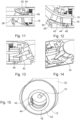
- Fig. 11 shows the spring plate 42 in the straight shaft 1. It is shown that the ball 44 of the spring plate 42 is inserted into an elongated receiving groove 48 in the pinion 18.
- the receiving groove 48 runs in the longitudinal direction of the shaft 1 and the ball 44 is positively connected to the receiving groove 48.
- the ball 44 therefore moves with the rotation of the pinion 18 and also moves in the longitudinal direction of the receiving groove 48.
- the side of the spring plate 42 that is opposite the ball 44 is fastened to the adjustment bushing 28. A rotation of the pinion 18 is thus transferred from the spring plate 42 to the adjustment bushing 28.
- the adjustment bushing 28 rotates with the spring plate 42.
- the spring plate 42 is connected to the adjustment bushing 28, for example by welding or gluing.
- the receiving groove 48 can also be prepared in the adjustment bushing 28.
- the ball 44 is connected to the adjustment bushing 28 and the spring plate 42 is welded or glued to the pinion 18.
- the ball 44 moves in a spherical receiving groove 48 in the pinion 18 in the longitudinal direction of the receiving groove 48.
- Distal fixation in the adjustment bushing 28 is achieved by means of gluing or welding. Proximal fixation is omitted.
- the positive locking of the ball 44 in the receiving groove 48 transmits the rotary movement via the spring plate 42 to the adjusting bush 28.
- Fig. 12 shows the spring plate 42 in the shaft 1 angled by 45°.
- the pinion 18 is rotated by 180° around its longitudinal axis compared to the straight shaft 1.
- the receiving groove 48 with the ball 44 is of course also rotated by 180°.
- the adjustment bushing 28 is also rotated by the spring plate 42.
- the driving pin 30 takes the distal shaft tip 32 with it, which also rotates by 180°. It is clear that the spring plate 42 has a greater distance from the flexible milling cutter 10 in the angled state than in the extended state.
- Fig. 13 shows a top view of the spring plate 42.
- the shaft 1 is angled by 22.5°.
- the rotation of the pinion 18 causes the spring plate 42 to rotate and the adjustment bushing 28 to rotate as well. This causes the spring plate 42 to twist.
- the ball 44 moves in the longitudinal direction of the receiving groove 48 when the pinion 18 rotates in the receiving groove 48.
- Fig. 14 shows the spring plate 42. It is clear that the spring plate 42 is twisted about its own longitudinal axis during rotation or the transmission of the rotary motion from the pinion 18 to the adjusting bushing 28. In the 22.5° position it is clear that the spring plate 42 is twisted towards the receiving groove 48 and is also twisted about its longitudinal axis. A corresponding flexibility of the spring plate 42 is a basic requirement for the function.
- Fig. 15 shows a cross-section through the proximal shaft section 2 with the eccentric locking bush 22 and the pinion 18.
- the ball 44 is positively inserted into the receiving groove 48 and follows the rotation of the receiving groove 48.
- the special spherical receiving groove 48 ensures that the ball 44 of the spring plate 42 is held in place by a positive fit and thus has to follow the rotational movement of the pinion 18.
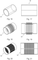
- Fig. 16 shows the silicone hose 34 according to the first embodiment.
- the silicone hose 34 is one way of realizing the flexible transmission element.
- the silicone hose 34 is glued at one end to the pinion 18 and the adjustment bushing 28.
- Fig. 17 shows a side view of the silicone hose 34.
- Fig. 18 shows a flexible transmission element according to a third embodiment.
- the transmission element is a flexible metal bellows 50.
- the metal bellows 50 is essentially a hollow, elongated metal tube. In the middle, the metal tube has folds that resemble the folds of a bellows or an accordion. The folds make the metal bellows 50 bendable or flexible.
- the metal bellows 50 can be attached to the pinion 18 and the adjustment bushing 28 by gluing or welding.
- Fig. 19 shows a side view of the metal bellows 50.
- Fig. 20 shows a flexible transmission element according to a fourth embodiment.
- the transmission element is a flexible metal tube 52.
- the metal tube 52 is essentially a thin, elongated metal tube.
- the metal tube 52 has slots/recesses that run in the radial direction of the metal tube 52. That is, the metal tube 52 has a gap geometry. The recesses make the metal tube 52 flexible.
- the metal tube 52 can be attached to the pinion 18 and the adjustment bushing 28 by gluing or welding.
- Fig. 21 shows a side view of the metal tube 52.
- Fig. 22 shows an extended shaft 1 according to a fifth embodiment.
- the roller bearing 26 is not a full ball bearing, but only has three or more balls 38.
- the receiving pin 25 of the outer tube 12 has three ball holes 54.
- the distal shaft tip 32 has a circumferential groove 56.
- the balls 38 are each inserted into the corresponding ball hole 54 through the filling opening 40.
- the closure is analogous to the first embodiment.
- the balls 38 rotate in their respective ball hole 54. This leads to slightly higher friction, since the rolling movement is only possible on the groove 56 of the distal shaft tip 32. However, significantly fewer balls 38 are required and assembly is faster.
- Fig. 23 shows a cross section through the distal shaft section 4 and the rolling bearing 26.
- the ball bores 54 are equally spaced in the circumferential direction.
- Fig. 24 shows an extended shaft 1 according to a sixth embodiment.
- the distal shaft tip 32 is fixed to the outer tube 12 by a rear locking mechanism 58.
- the distal shaft tip 32 In order to be able to implement the rear locking mechanism 58, the distal shaft tip 32 must be made of a flexible material, such as plastic.
- the distal shaft tip 32 is bent open for assembly and locked into the projections of the outer tube 12.
- the rotation is transmitted by a lateral driving pin 60, since space has been created by the missing balls.
- the driving pin 60 protrudes from the adjustment bushing 28 and rotates with the adjustment bushing 28.
- the outer tube 12 has a recess 61 in which the driving pin 60 is movable.
- the driving pin 60 runs through the recess 61 and is positively connected to a bulge of the distal shaft tip 32.
- Fig. 25 shows a cross section through the distal shaft tip 32.
- the adjustment bushing 28 has the protruding driving pin 60, which engages in the distal shaft tip 32.
- the driving pin 60 penetrates the outer tube 12 through the recess 61.
- the recess 61 encompasses half the circumference of the outer tube 12.
- the driving pin 60 transfers the rotation of the adjustment bushing 28 to the distal shaft tip 32.
- Fig. 26 shows an angled shaft 1 according to a seventh embodiment.
- the shaft 1 does not have a milling cutter, but has jaw parts or scissor blades 62 that protrude from the distal shaft section. A user can use the jaw parts 62 to grip or fix objects.
- a maximum angle of 90 degrees can be achieved by cutting at an angle of 45 degrees (instead of 22.5 degrees) (not shown).
- the more elliptical shape of the cutting surface increases the lateral overhang of the shaft edges in the area of the swivel joint (particularly in the intermediate position at half the adjustment range).
- the overhang can be reduced by using special curves.
- angle head enables particularly rigid instruments that can maintain their position even under high loads.
- the flexible cutter 10 can have a special section for the bending area, which on the one hand can withstand the movement of the instrument tip and on the other hand can transmit the torque.
- This can be, for example, a thin wire, braided strands or a universal joint or the like.
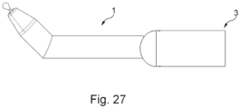
- Fig. 27 shows the shaft 1 with a medical hand instrument 3.
- the shafts of all embodiments are suitable for the medical hand instrument 3 and can be connected to the medical hand instrument 3.
Landscapes
- Health & Medical Sciences (AREA)
- Life Sciences & Earth Sciences (AREA)
- Surgery (AREA)
- Engineering & Computer Science (AREA)
- Heart & Thoracic Surgery (AREA)
- Medical Informatics (AREA)
- Nuclear Medicine, Radiotherapy & Molecular Imaging (AREA)
- Veterinary Medicine (AREA)
- Public Health (AREA)
- General Health & Medical Sciences (AREA)
- Animal Behavior & Ethology (AREA)
- Biomedical Technology (AREA)
- Molecular Biology (AREA)
- Physics & Mathematics (AREA)
- Biophysics (AREA)
- Radiology & Medical Imaging (AREA)
- Pathology (AREA)
- Optics & Photonics (AREA)
- Orthopedic Medicine & Surgery (AREA)
- Mechanical Engineering (AREA)
- Dentistry (AREA)
- Oral & Maxillofacial Surgery (AREA)
- Ophthalmology & Optometry (AREA)
- Flexible Shafts (AREA)
- Surgical Instruments (AREA)
Applications Claiming Priority (2)
| Application Number | Priority Date | Filing Date | Title |
|---|---|---|---|
| DE102021119386.9A DE102021119386A1 (de) | 2021-07-27 | 2021-07-27 | Abwinkelbarer Schaft für ein medizinisches Handinstrument |
| PCT/EP2022/070333 WO2023006541A1 (de) | 2021-07-27 | 2022-07-20 | Abwinkelbarer schaft für ein medizinisches handinstrument |
Publications (2)
| Publication Number | Publication Date |
|---|---|
| EP4351448A1 EP4351448A1 (de) | 2024-04-17 |
| EP4351448B1 true EP4351448B1 (de) | 2024-09-04 |
Family
ID=83004975
Family Applications (1)
| Application Number | Title | Priority Date | Filing Date |
|---|---|---|---|
| EP22757494.4A Active EP4351448B1 (de) | 2021-07-27 | 2022-07-20 | Abwinkelbarer schaft für ein medizinisches handinstrument |
Country Status (6)
| Country | Link |
|---|---|
| US (1) | US20250325173A1 (enExample) |
| EP (1) | EP4351448B1 (enExample) |
| JP (1) | JP2024525979A (enExample) |
| CN (1) | CN117677352A (enExample) |
| DE (1) | DE102021119386A1 (enExample) |
| WO (1) | WO2023006541A1 (enExample) |
Families Citing this family (6)
| Publication number | Priority date | Publication date | Assignee | Title |
|---|---|---|---|---|
| DE102022101885A1 (de) * | 2022-01-27 | 2023-07-27 | Aesculap Ag | Schaft eines oder für ein medizinisches Handinstrument |
| DE102022119982A1 (de) * | 2022-08-09 | 2024-02-15 | Aesculap Ag | Motorhandstück mit rotierbarem Bedienelement sowie Medizinisches Handinstrument |
| CN117898788B (zh) * | 2024-01-16 | 2025-02-18 | 北京和华瑞博医疗科技有限公司 | 弯髋臼锉连杆、末端执行器与手术机器人 |
| CN117883145B (zh) * | 2024-01-16 | 2025-01-14 | 北京和华瑞博医疗科技有限公司 | 髋臼锉连杆、末端执行器及手术机器人 |
| DE102024116125A1 (de) | 2024-06-10 | 2025-12-11 | Aesculap Ag | Schaftinstrument für laparoskopische und/oder endoskopische Eingriffe |
| DE102024116129A1 (de) | 2024-06-10 | 2025-12-11 | Aesculap Ag | Schaftanordnung für ein medizinisches Instrument |
Family Cites Families (9)
| Publication number | Priority date | Publication date | Assignee | Title |
|---|---|---|---|---|
| US5575799A (en) * | 1995-03-30 | 1996-11-19 | United States Surgical Corporation | Articulating surgical apparatus |
| AU4569697A (en) * | 1997-10-28 | 1999-05-17 | Romolo Bertani | Device for supporting a mandrel with angular transmission |
| US6050989A (en) * | 1998-08-24 | 2000-04-18 | Linvatec Corporation | Angularly adjustable powered surgical handpiece |
| RU2181566C2 (ru) * | 2000-01-10 | 2002-04-27 | Дубровский Аркадий Вениаминович | Управляемый поворотный механизм |
| RU2284160C2 (ru) * | 2002-06-24 | 2006-09-27 | Аркадий Вениаминович Дубровский | Устройство для поворота инструмента с дистанционным управлением |
| US8128250B2 (en) | 2010-01-11 | 2012-03-06 | Robert Bosch Gmbh | Articulating drill with illumination |
| DE102011100695B4 (de) | 2011-05-06 | 2013-10-31 | Richard Wolf Gmbh | Mikrofraktor |
| EP3260061B1 (en) | 2013-11-29 | 2020-01-08 | Chongqing Xishan Science & Technology Co.,Ltd. | Lateral grinding drill with continuously variable angle and driving component thereof |
| DE102017010033A1 (de) | 2017-10-27 | 2019-05-02 | Joimax Gmbh | Medizinische Vorrichtung |
-
2021
- 2021-07-27 DE DE102021119386.9A patent/DE102021119386A1/de not_active Withdrawn
-
2022
- 2022-07-20 CN CN202280050550.7A patent/CN117677352A/zh active Pending
- 2022-07-20 US US18/292,428 patent/US20250325173A1/en active Pending
- 2022-07-20 WO PCT/EP2022/070333 patent/WO2023006541A1/de not_active Ceased
- 2022-07-20 EP EP22757494.4A patent/EP4351448B1/de active Active
- 2022-07-20 JP JP2024504871A patent/JP2024525979A/ja active Pending
Also Published As
| Publication number | Publication date |
|---|---|
| CN117677352A (zh) | 2024-03-08 |
| JP2024525979A (ja) | 2024-07-12 |
| DE102021119386A1 (de) | 2023-02-02 |
| EP4351448A1 (de) | 2024-04-17 |
| WO2023006541A1 (de) | 2023-02-02 |
| US20250325173A1 (en) | 2025-10-23 |
Similar Documents
| Publication | Publication Date | Title |
|---|---|---|
| EP4351448A1 (de) | Abwinkelbarer schaft für ein medizinisches handinstrument | |
| EP1484024B1 (de) | Chirurgisches Instrument mit Instrumentengriff und Nullpunkteinstellung | |
| EP1464289B1 (de) | Chirurgisches Instrument, bei welchem Bewegungen des Instrumentskopfs und des Effektors entkoppelt sind | |
| EP1464290B1 (de) | Chirurgisches Instrument | |
| EP1235522B1 (de) | Chirurgisches instrument für minimal invasive eingriffe | |
| EP3528688B1 (de) | Medizinische vorrichtung | |
| DE19850520B4 (de) | Medizinisches Instrument zum Abtragen von Gewebe | |
| DE102012222755B4 (de) | Instrument, insbesondere medizinisch endoskopisches Instrument oder Technoskop | |
| WO2015081946A1 (de) | Instrument, insbesondere ein medizinisch-endoskopisches instrument oder technoskop | |
| EP2884904B1 (de) | Chirurgisches instrument | |
| DE102009042150A1 (de) | Chirurgisches Instrument | |
| DE102009042491A1 (de) | Chirurgisches Instrument | |
| WO2010136275A1 (de) | Steuerungsvorrichtung | |
| EP1486172A1 (de) | Chirurgisches Instrument | |
| EP3695793B1 (de) | Medizinisches instrument | |
| EP2601895B1 (de) | Medizinisches Instrument | |
| EP4321107A1 (de) | Medizinisches motorhandstück mit rast- und/oder anschlageinheit | |
| DE9300161U1 (de) | Chirurgisches Instrument | |
| WO2023006649A1 (de) | Lagerungsanordnung einer taumelscheibe auf einer welle und chirurgisches instrument | |
| DE10036108A1 (de) | Chirurgisches Instrument für minimal invasive Eingriffe | |
| EP4321109A1 (de) | Medizinisches motorhandstück mit winkelstellring und medizinisches handinstrument | |
| EP2403418B1 (de) | Medizinisches instrument | |
| EP3695790A1 (de) | Medizinisches instrument | |
| EP4271286B1 (de) | Schaft eines oder für ein medizinisches handinstrument | |
| EP3498147A1 (de) | Längliches schaftinstrument |
Legal Events
| Date | Code | Title | Description |
|---|---|---|---|
| STAA | Information on the status of an ep patent application or granted ep patent |
Free format text: STATUS: UNKNOWN |
|
| STAA | Information on the status of an ep patent application or granted ep patent |
Free format text: STATUS: THE INTERNATIONAL PUBLICATION HAS BEEN MADE |
|
| PUAI | Public reference made under article 153(3) epc to a published international application that has entered the european phase |
Free format text: ORIGINAL CODE: 0009012 |
|
| STAA | Information on the status of an ep patent application or granted ep patent |
Free format text: STATUS: REQUEST FOR EXAMINATION WAS MADE |
|
| GRAP | Despatch of communication of intention to grant a patent |
Free format text: ORIGINAL CODE: EPIDOSNIGR1 |
|
| STAA | Information on the status of an ep patent application or granted ep patent |
Free format text: STATUS: GRANT OF PATENT IS INTENDED |
|
| 17P | Request for examination filed |
Effective date: 20230322 |
|
| AK | Designated contracting states |
Kind code of ref document: A1 Designated state(s): AL AT BE BG CH CY CZ DE DK EE ES FI FR GB GR HR HU IE IS IT LI LT LU LV MC MK MT NL NO PL PT RO RS SE SI SK SM TR |
|
| DAV | Request for validation of the european patent (deleted) | ||
| DAX | Request for extension of the european patent (deleted) | ||
| INTG | Intention to grant announced |
Effective date: 20240405 |
|
| GRAS | Grant fee paid |
Free format text: ORIGINAL CODE: EPIDOSNIGR3 |
|
| GRAA | (expected) grant |
Free format text: ORIGINAL CODE: 0009210 |
|
| STAA | Information on the status of an ep patent application or granted ep patent |
Free format text: STATUS: THE PATENT HAS BEEN GRANTED |
|
| AK | Designated contracting states |
Kind code of ref document: B1 Designated state(s): AL AT BE BG CH CY CZ DE DK EE ES FI FR GB GR HR HU IE IS IT LI LT LU LV MC MK MT NL NO PL PT RO RS SE SI SK SM TR |
|
| REG | Reference to a national code |
Ref country code: GB Ref legal event code: FG4D Free format text: NOT ENGLISH |
|
| REG | Reference to a national code |
Ref country code: CH Ref legal event code: EP |
|
| REG | Reference to a national code |
Ref country code: DE Ref legal event code: R096 Ref document number: 502022001623 Country of ref document: DE |
|
| REG | Reference to a national code |
Ref country code: IE Ref legal event code: FG4D Free format text: LANGUAGE OF EP DOCUMENT: GERMAN |
|
| REG | Reference to a national code |
Ref country code: LT Ref legal event code: MG9D |
|
| REG | Reference to a national code |
Ref country code: NL Ref legal event code: MP Effective date: 20240904 |
|
| PG25 | Lapsed in a contracting state [announced via postgrant information from national office to epo] |
Ref country code: NO Free format text: LAPSE BECAUSE OF FAILURE TO SUBMIT A TRANSLATION OF THE DESCRIPTION OR TO PAY THE FEE WITHIN THE PRESCRIBED TIME-LIMIT Effective date: 20241204 |
|
| PG25 | Lapsed in a contracting state [announced via postgrant information from national office to epo] |
Ref country code: GR Free format text: LAPSE BECAUSE OF FAILURE TO SUBMIT A TRANSLATION OF THE DESCRIPTION OR TO PAY THE FEE WITHIN THE PRESCRIBED TIME-LIMIT Effective date: 20241205 Ref country code: FI Free format text: LAPSE BECAUSE OF FAILURE TO SUBMIT A TRANSLATION OF THE DESCRIPTION OR TO PAY THE FEE WITHIN THE PRESCRIBED TIME-LIMIT Effective date: 20240904 |
|
| PG25 | Lapsed in a contracting state [announced via postgrant information from national office to epo] |
Ref country code: BG Free format text: LAPSE BECAUSE OF FAILURE TO SUBMIT A TRANSLATION OF THE DESCRIPTION OR TO PAY THE FEE WITHIN THE PRESCRIBED TIME-LIMIT Effective date: 20240904 |
|
| PG25 | Lapsed in a contracting state [announced via postgrant information from national office to epo] |
Ref country code: LV Free format text: LAPSE BECAUSE OF FAILURE TO SUBMIT A TRANSLATION OF THE DESCRIPTION OR TO PAY THE FEE WITHIN THE PRESCRIBED TIME-LIMIT Effective date: 20240904 |
|
| PG25 | Lapsed in a contracting state [announced via postgrant information from national office to epo] |
Ref country code: HR Free format text: LAPSE BECAUSE OF FAILURE TO SUBMIT A TRANSLATION OF THE DESCRIPTION OR TO PAY THE FEE WITHIN THE PRESCRIBED TIME-LIMIT Effective date: 20240904 |
|
| PG25 | Lapsed in a contracting state [announced via postgrant information from national office to epo] |
Ref country code: RS Free format text: LAPSE BECAUSE OF FAILURE TO SUBMIT A TRANSLATION OF THE DESCRIPTION OR TO PAY THE FEE WITHIN THE PRESCRIBED TIME-LIMIT Effective date: 20241204 Ref country code: ES Free format text: LAPSE BECAUSE OF FAILURE TO SUBMIT A TRANSLATION OF THE DESCRIPTION OR TO PAY THE FEE WITHIN THE PRESCRIBED TIME-LIMIT Effective date: 20240904 |
|
| PG25 | Lapsed in a contracting state [announced via postgrant information from national office to epo] |
Ref country code: RS Free format text: LAPSE BECAUSE OF FAILURE TO SUBMIT A TRANSLATION OF THE DESCRIPTION OR TO PAY THE FEE WITHIN THE PRESCRIBED TIME-LIMIT Effective date: 20241204 Ref country code: NO Free format text: LAPSE BECAUSE OF FAILURE TO SUBMIT A TRANSLATION OF THE DESCRIPTION OR TO PAY THE FEE WITHIN THE PRESCRIBED TIME-LIMIT Effective date: 20241204 Ref country code: LV Free format text: LAPSE BECAUSE OF FAILURE TO SUBMIT A TRANSLATION OF THE DESCRIPTION OR TO PAY THE FEE WITHIN THE PRESCRIBED TIME-LIMIT Effective date: 20240904 Ref country code: HR Free format text: LAPSE BECAUSE OF FAILURE TO SUBMIT A TRANSLATION OF THE DESCRIPTION OR TO PAY THE FEE WITHIN THE PRESCRIBED TIME-LIMIT Effective date: 20240904 Ref country code: GR Free format text: LAPSE BECAUSE OF FAILURE TO SUBMIT A TRANSLATION OF THE DESCRIPTION OR TO PAY THE FEE WITHIN THE PRESCRIBED TIME-LIMIT Effective date: 20241205 Ref country code: FI Free format text: LAPSE BECAUSE OF FAILURE TO SUBMIT A TRANSLATION OF THE DESCRIPTION OR TO PAY THE FEE WITHIN THE PRESCRIBED TIME-LIMIT Effective date: 20240904 Ref country code: ES Free format text: LAPSE BECAUSE OF FAILURE TO SUBMIT A TRANSLATION OF THE DESCRIPTION OR TO PAY THE FEE WITHIN THE PRESCRIBED TIME-LIMIT Effective date: 20240904 Ref country code: BG Free format text: LAPSE BECAUSE OF FAILURE TO SUBMIT A TRANSLATION OF THE DESCRIPTION OR TO PAY THE FEE WITHIN THE PRESCRIBED TIME-LIMIT Effective date: 20240904 |
|
| PG25 | Lapsed in a contracting state [announced via postgrant information from national office to epo] |
Ref country code: NL Free format text: LAPSE BECAUSE OF FAILURE TO SUBMIT A TRANSLATION OF THE DESCRIPTION OR TO PAY THE FEE WITHIN THE PRESCRIBED TIME-LIMIT Effective date: 20240904 |
|
| PG25 | Lapsed in a contracting state [announced via postgrant information from national office to epo] |
Ref country code: PT Free format text: LAPSE BECAUSE OF FAILURE TO SUBMIT A TRANSLATION OF THE DESCRIPTION OR TO PAY THE FEE WITHIN THE PRESCRIBED TIME-LIMIT Effective date: 20250106 Ref country code: IS Free format text: LAPSE BECAUSE OF FAILURE TO SUBMIT A TRANSLATION OF THE DESCRIPTION OR TO PAY THE FEE WITHIN THE PRESCRIBED TIME-LIMIT Effective date: 20250104 |
|
| PG25 | Lapsed in a contracting state [announced via postgrant information from national office to epo] |
Ref country code: RO Free format text: LAPSE BECAUSE OF FAILURE TO SUBMIT A TRANSLATION OF THE DESCRIPTION OR TO PAY THE FEE WITHIN THE PRESCRIBED TIME-LIMIT Effective date: 20240904 Ref country code: SM Free format text: LAPSE BECAUSE OF FAILURE TO SUBMIT A TRANSLATION OF THE DESCRIPTION OR TO PAY THE FEE WITHIN THE PRESCRIBED TIME-LIMIT Effective date: 20240904 |
|
| PG25 | Lapsed in a contracting state [announced via postgrant information from national office to epo] |
Ref country code: EE Free format text: LAPSE BECAUSE OF FAILURE TO SUBMIT A TRANSLATION OF THE DESCRIPTION OR TO PAY THE FEE WITHIN THE PRESCRIBED TIME-LIMIT Effective date: 20240904 |
|
| PG25 | Lapsed in a contracting state [announced via postgrant information from national office to epo] |
Ref country code: CZ Free format text: LAPSE BECAUSE OF FAILURE TO SUBMIT A TRANSLATION OF THE DESCRIPTION OR TO PAY THE FEE WITHIN THE PRESCRIBED TIME-LIMIT Effective date: 20240904 Ref country code: PL Free format text: LAPSE BECAUSE OF FAILURE TO SUBMIT A TRANSLATION OF THE DESCRIPTION OR TO PAY THE FEE WITHIN THE PRESCRIBED TIME-LIMIT Effective date: 20240904 |
|
| PG25 | Lapsed in a contracting state [announced via postgrant information from national office to epo] |
Ref country code: IT Free format text: LAPSE BECAUSE OF FAILURE TO SUBMIT A TRANSLATION OF THE DESCRIPTION OR TO PAY THE FEE WITHIN THE PRESCRIBED TIME-LIMIT Effective date: 20240904 Ref country code: SK Free format text: LAPSE BECAUSE OF FAILURE TO SUBMIT A TRANSLATION OF THE DESCRIPTION OR TO PAY THE FEE WITHIN THE PRESCRIBED TIME-LIMIT Effective date: 20240904 |
|
| REG | Reference to a national code |
Ref country code: DE Ref legal event code: R097 Ref document number: 502022001623 Country of ref document: DE |
|
| PG25 | Lapsed in a contracting state [announced via postgrant information from national office to epo] |
Ref country code: DK Free format text: LAPSE BECAUSE OF FAILURE TO SUBMIT A TRANSLATION OF THE DESCRIPTION OR TO PAY THE FEE WITHIN THE PRESCRIBED TIME-LIMIT Effective date: 20240904 |
|
| PLBE | No opposition filed within time limit |
Free format text: ORIGINAL CODE: 0009261 |
|
| STAA | Information on the status of an ep patent application or granted ep patent |
Free format text: STATUS: NO OPPOSITION FILED WITHIN TIME LIMIT |
|
| 26N | No opposition filed |
Effective date: 20250605 |
|
| PG25 | Lapsed in a contracting state [announced via postgrant information from national office to epo] |
Ref country code: SE Free format text: LAPSE BECAUSE OF FAILURE TO SUBMIT A TRANSLATION OF THE DESCRIPTION OR TO PAY THE FEE WITHIN THE PRESCRIBED TIME-LIMIT Effective date: 20240904 |
|
| PGFP | Annual fee paid to national office [announced via postgrant information from national office to epo] |
Ref country code: DE Payment date: 20250722 Year of fee payment: 4 |
|
| PGFP | Annual fee paid to national office [announced via postgrant information from national office to epo] |
Ref country code: FR Payment date: 20250723 Year of fee payment: 4 Ref country code: AT Payment date: 20251020 Year of fee payment: 4 |
|
| PGFP | Annual fee paid to national office [announced via postgrant information from national office to epo] |
Ref country code: CH Payment date: 20250801 Year of fee payment: 4 |
|
| PG25 | Lapsed in a contracting state [announced via postgrant information from national office to epo] |
Ref country code: LU Free format text: LAPSE BECAUSE OF NON-PAYMENT OF DUE FEES Effective date: 20250720 |
|
| REG | Reference to a national code |
Ref country code: BE Ref legal event code: MM Effective date: 20250731 |
|
| PG25 | Lapsed in a contracting state [announced via postgrant information from national office to epo] |
Ref country code: BE Free format text: LAPSE BECAUSE OF NON-PAYMENT OF DUE FEES Effective date: 20250731 |