EP4350797A1 - Lithium primary battery - Google Patents
Lithium primary battery Download PDFInfo
- Publication number
- EP4350797A1 EP4350797A1 EP22815739.2A EP22815739A EP4350797A1 EP 4350797 A1 EP4350797 A1 EP 4350797A1 EP 22815739 A EP22815739 A EP 22815739A EP 4350797 A1 EP4350797 A1 EP 4350797A1
- Authority
- EP
- European Patent Office
- Prior art keywords
- positive electrode
- electrode
- main surface
- negative electrode
- lithium
- Prior art date
- Legal status (The legal status is an assumption and is not a legal conclusion. Google has not performed a legal analysis and makes no representation as to the accuracy of the status listed.)
- Pending
Links
Images


Classifications
-
- H—ELECTRICITY
- H01—ELECTRIC ELEMENTS
- H01M—PROCESSES OR MEANS, e.g. BATTERIES, FOR THE DIRECT CONVERSION OF CHEMICAL ENERGY INTO ELECTRICAL ENERGY
- H01M10/00—Secondary cells; Manufacture thereof
- H01M10/04—Construction or manufacture in general
- H01M10/0431—Cells with wound or folded electrodes
-
- H—ELECTRICITY
- H01—ELECTRIC ELEMENTS
- H01M—PROCESSES OR MEANS, e.g. BATTERIES, FOR THE DIRECT CONVERSION OF CHEMICAL ENERGY INTO ELECTRICAL ENERGY
- H01M4/00—Electrodes
- H01M4/02—Electrodes composed of, or comprising, active material
- H01M4/06—Electrodes for primary cells
-
- H—ELECTRICITY
- H01—ELECTRIC ELEMENTS
- H01M—PROCESSES OR MEANS, e.g. BATTERIES, FOR THE DIRECT CONVERSION OF CHEMICAL ENERGY INTO ELECTRICAL ENERGY
- H01M4/00—Electrodes
- H01M4/02—Electrodes composed of, or comprising, active material
- H01M4/36—Selection of substances as active materials, active masses, active liquids
- H01M4/38—Selection of substances as active materials, active masses, active liquids of elements or alloys
- H01M4/381—Alkaline or alkaline earth metals elements
- H01M4/382—Lithium
-
- H—ELECTRICITY
- H01—ELECTRIC ELEMENTS
- H01M—PROCESSES OR MEANS, e.g. BATTERIES, FOR THE DIRECT CONVERSION OF CHEMICAL ENERGY INTO ELECTRICAL ENERGY
- H01M4/00—Electrodes
- H01M4/02—Electrodes composed of, or comprising, active material
- H01M4/36—Selection of substances as active materials, active masses, active liquids
- H01M4/38—Selection of substances as active materials, active masses, active liquids of elements or alloys
- H01M4/40—Alloys based on alkali metals
- H01M4/405—Alloys based on lithium
-
- H—ELECTRICITY
- H01—ELECTRIC ELEMENTS
- H01M—PROCESSES OR MEANS, e.g. BATTERIES, FOR THE DIRECT CONVERSION OF CHEMICAL ENERGY INTO ELECTRICAL ENERGY
- H01M4/00—Electrodes
- H01M4/02—Electrodes composed of, or comprising, active material
- H01M4/36—Selection of substances as active materials, active masses, active liquids
- H01M4/48—Selection of substances as active materials, active masses, active liquids of inorganic oxides or hydroxides
- H01M4/50—Selection of substances as active materials, active masses, active liquids of inorganic oxides or hydroxides of manganese
- H01M4/502—Selection of substances as active materials, active masses, active liquids of inorganic oxides or hydroxides of manganese for non-aqueous cells
-
- H—ELECTRICITY
- H01—ELECTRIC ELEMENTS
- H01M—PROCESSES OR MEANS, e.g. BATTERIES, FOR THE DIRECT CONVERSION OF CHEMICAL ENERGY INTO ELECTRICAL ENERGY
- H01M4/00—Electrodes
- H01M4/02—Electrodes composed of, or comprising, active material
- H01M4/36—Selection of substances as active materials, active masses, active liquids
- H01M4/48—Selection of substances as active materials, active masses, active liquids of inorganic oxides or hydroxides
- H01M4/50—Selection of substances as active materials, active masses, active liquids of inorganic oxides or hydroxides of manganese
- H01M4/505—Selection of substances as active materials, active masses, active liquids of inorganic oxides or hydroxides of manganese of mixed oxides or hydroxides containing manganese for inserting or intercalating light metals, e.g. LiMn2O4 or LiMn2OxFy
-
- H—ELECTRICITY
- H01—ELECTRIC ELEMENTS
- H01M—PROCESSES OR MEANS, e.g. BATTERIES, FOR THE DIRECT CONVERSION OF CHEMICAL ENERGY INTO ELECTRICAL ENERGY
- H01M50/00—Constructional details or processes of manufacture of the non-active parts of electrochemical cells other than fuel cells, e.g. hybrid cells
- H01M50/10—Primary casings; Jackets or wrappings
- H01M50/102—Primary casings; Jackets or wrappings characterised by their shape or physical structure
- H01M50/107—Primary casings; Jackets or wrappings characterised by their shape or physical structure having curved cross-section, e.g. round or elliptic
-
- H—ELECTRICITY
- H01—ELECTRIC ELEMENTS
- H01M—PROCESSES OR MEANS, e.g. BATTERIES, FOR THE DIRECT CONVERSION OF CHEMICAL ENERGY INTO ELECTRICAL ENERGY
- H01M50/00—Constructional details or processes of manufacture of the non-active parts of electrochemical cells other than fuel cells, e.g. hybrid cells
- H01M50/10—Primary casings; Jackets or wrappings
- H01M50/116—Primary casings; Jackets or wrappings characterised by the material
- H01M50/117—Inorganic material
- H01M50/119—Metals
-
- H—ELECTRICITY
- H01—ELECTRIC ELEMENTS
- H01M—PROCESSES OR MEANS, e.g. BATTERIES, FOR THE DIRECT CONVERSION OF CHEMICAL ENERGY INTO ELECTRICAL ENERGY
- H01M50/00—Constructional details or processes of manufacture of the non-active parts of electrochemical cells other than fuel cells, e.g. hybrid cells
- H01M50/10—Primary casings; Jackets or wrappings
- H01M50/131—Primary casings; Jackets or wrappings characterised by physical properties, e.g. gas permeability, size or heat resistance
- H01M50/133—Thickness
-
- H—ELECTRICITY
- H01—ELECTRIC ELEMENTS
- H01M—PROCESSES OR MEANS, e.g. BATTERIES, FOR THE DIRECT CONVERSION OF CHEMICAL ENERGY INTO ELECTRICAL ENERGY
- H01M50/00—Constructional details or processes of manufacture of the non-active parts of electrochemical cells other than fuel cells, e.g. hybrid cells
- H01M50/10—Primary casings; Jackets or wrappings
- H01M50/147—Lids or covers
- H01M50/166—Lids or covers characterised by the methods of assembling casings with lids
- H01M50/169—Lids or covers characterised by the methods of assembling casings with lids by welding, brazing or soldering
-
- H—ELECTRICITY
- H01—ELECTRIC ELEMENTS
- H01M—PROCESSES OR MEANS, e.g. BATTERIES, FOR THE DIRECT CONVERSION OF CHEMICAL ENERGY INTO ELECTRICAL ENERGY
- H01M50/00—Constructional details or processes of manufacture of the non-active parts of electrochemical cells other than fuel cells, e.g. hybrid cells
- H01M50/40—Separators; Membranes; Diaphragms; Spacing elements inside cells
- H01M50/489—Separators, membranes, diaphragms or spacing elements inside the cells, characterised by their physical properties, e.g. swelling degree, hydrophilicity or shut down properties
-
- H—ELECTRICITY
- H01—ELECTRIC ELEMENTS
- H01M—PROCESSES OR MEANS, e.g. BATTERIES, FOR THE DIRECT CONVERSION OF CHEMICAL ENERGY INTO ELECTRICAL ENERGY
- H01M6/00—Primary cells; Manufacture thereof
- H01M6/14—Cells with non-aqueous electrolyte
- H01M6/16—Cells with non-aqueous electrolyte with organic electrolyte
-
- H—ELECTRICITY
- H01—ELECTRIC ELEMENTS
- H01M—PROCESSES OR MEANS, e.g. BATTERIES, FOR THE DIRECT CONVERSION OF CHEMICAL ENERGY INTO ELECTRICAL ENERGY
- H01M4/00—Electrodes
- H01M4/02—Electrodes composed of, or comprising, active material
- H01M2004/021—Physical characteristics, e.g. porosity, surface area
-
- Y—GENERAL TAGGING OF NEW TECHNOLOGICAL DEVELOPMENTS; GENERAL TAGGING OF CROSS-SECTIONAL TECHNOLOGIES SPANNING OVER SEVERAL SECTIONS OF THE IPC; TECHNICAL SUBJECTS COVERED BY FORMER USPC CROSS-REFERENCE ART COLLECTIONS [XRACs] AND DIGESTS
- Y02—TECHNOLOGIES OR APPLICATIONS FOR MITIGATION OR ADAPTATION AGAINST CLIMATE CHANGE
- Y02E—REDUCTION OF GREENHOUSE GAS [GHG] EMISSIONS, RELATED TO ENERGY GENERATION, TRANSMISSION OR DISTRIBUTION
- Y02E60/00—Enabling technologies; Technologies with a potential or indirect contribution to GHG emissions mitigation
- Y02E60/10—Energy storage using batteries
-
- Y—GENERAL TAGGING OF NEW TECHNOLOGICAL DEVELOPMENTS; GENERAL TAGGING OF CROSS-SECTIONAL TECHNOLOGIES SPANNING OVER SEVERAL SECTIONS OF THE IPC; TECHNICAL SUBJECTS COVERED BY FORMER USPC CROSS-REFERENCE ART COLLECTIONS [XRACs] AND DIGESTS
- Y02—TECHNOLOGIES OR APPLICATIONS FOR MITIGATION OR ADAPTATION AGAINST CLIMATE CHANGE
- Y02P—CLIMATE CHANGE MITIGATION TECHNOLOGIES IN THE PRODUCTION OR PROCESSING OF GOODS
- Y02P70/00—Climate change mitigation technologies in the production process for final industrial or consumer products
- Y02P70/50—Manufacturing or production processes characterised by the final manufactured product
Definitions
- the present disclosure relates to a lithium primary battery.
- ICT Information and Communication Technology
- DX digital transformation
- One of devices that are widely used precedingly in the ICT is, for example, a smart meter.
- Devices used for such applications may often employ primary batteries as an independent power supply when a power source is not available from electric wires.
- the primary batteries used for such applications require various performance characteristics such as long life, high capacity, and stable discharge at various currents, from a high pulsed discharge current for communications in ICT to a low current for normal operations. From the viewpoint of ensuring such performance, demand for primary batteries with large capacity increases.
- PTL 1 proposes wound-electrode assembly for a cylindrical non-aqueous electrolyte battery.
- wound-electrode assembly positive and negative electrodes and separators are wound such that the number of windings which is defined by a winding-starting end and a winding-terminating end of a positive electrode including is greater than or equal to 1.0 and less than or equal to 4.0.
- the positive electrode sheet is obtained by a particular manufacturing method
- PTL 2 proposes that, in a wound-electrode assembly of a cylindrical non-aqueous electrolyte primary battery, a positive electrode with a thickness of greater than or equal to 1.4 mm is used, and 2 sheets of resin microporous films with a thickness of 7 ⁇ m to 20 ⁇ m are disposed between a positive electrode active material layer and a negative electrode active material layer.
- PTL 3 proposes the use of a wound-electrode assembly for a lithium primary battery.
- the wound-electrode assembly uses a positive electrode containing manganese dioxide and a negative electrode containing at least one substance selected from the group consisting of metallic lithium and lithium alloys and having a first main surface and a second main surface opposing the first main surface. The entireties of the first main surface and the second main surface faces the positive electrode.
- the total area of the first main surface and the second main surface is greater than or equal to 100 cm 2 and less than or equal to 180 cm 2 .
- the size (for example, the diameter) of the battery is increased, or the thicknesses of the electrodes in the wound-electrode assembly is increased.
- the discharging of the lithium primary battery with the outer diameter being large and the thickness of the wound-electrode assembly being great may cause various problems in the portions that face each other.
- the problems include expansions of the thickness of the positive electrode, decreases in the thickness of the negative electrode, and changes in the thickness of the separators. Consequently, it is difficult to keep the balance of thickness at various parts of the wound-electrode assembly to be uniform. It is also difficult to keep the electrolyte retention amount of the positive electrode and the separator to be uniform. Consequently, it is more likely to cause unevenness in discharge reactions.
- the lithium primary battery with a large outer diameter may provide large unevenness in discharge reactions since the number of windings of the electrode assembly is greater and the electrode area is greater.
- the positive electrode expands, increasing its thickness.
- the lithium in the negative electrode undergoes dissolution, reducing its thickness. Therefore, as the thickness of the electrodes is greater or the number of windings is greater, the amount of change in thickness during discharge becomes greater, hardly keeping the balance of thickness at the part where the positive electrode and the negative electrode face each other to be uniform to some degree. Consequently, the discharge reaction in the wound-electrode assembly does not undergo uniformly inside, causing differences from one part to another inside the electrode assembly.
- a separator is inserted between the positive electrode and the negative electrode to provide electrical insulation and retain the electrolyte. The separator has the function of alleviating the stress associated with changes in thickness of the electrodes to a slight degree.
- the separator is difficult to sufficiently alleviate the stress associated with changes in the thickness of the electrodes.
- the thickness of the separator changes, the amount of the electrolyte retained by the separators accordingly changes.
- Adverse effects caused by changes in thickness of the electrodes and the separator in the electrode assembly are insignificant at the initial stage of discharge, but as the discharge progresses, adverse effects tend to be more significant. For example, when a high pulsed discharge current for ICT communication is passed at an intermediate level of depth of discharge of 40% to 60%, a large voltage drop may occur, making communication impossible. On the other hand, at a final stage of discharge at an even deeper depth of discharge of 80% to 90%, such a phenomenon may be observed that a voltage drop is small so communication is possible even when a high pulsed discharge current for ICT communication is passed. There is a need for a long life and high capacity lithium primary battery capable of performing stable discharge at various levels of current, from high pulsed discharge currents for ICT communication to low currents for normal operations, irrespective of depth of discharge of the battery.
- a lithium primary battery includes an outer can, and a wound-electrode assembly and a non-aqueous electrolyte that are accommodated in the outer can.
- the wound-electrode assembly includes: a positive electrode having a sheet shape; a negative electrode having a sheet shape having a first main surface and a second main surface opposed to each other; and a separator provided between the positive electrode and the negative electrode, the positive electrode, the negative electrode, and the separator being stacked and wound together.
- the positive electrode includes a positive electrode mixture containing manganese dioxide.
- the negative electrode includes at least one selected from the group consisting of metallic lithium and metallic lithium containing lithium alloy.
- the first main surface of the negative electrode and an entirety of the second main surface of the negative electrode face the positive electrode.
- a total area S of the first main surface and the second main surface of the negative electrode satisfies 250 cm 2 ⁇ S ⁇ 700 cm 2 .
- a thickness Tp of the positive electrode satisfies 0.8 mm ⁇ Tp ⁇ 1.4 mm.
- An outer diameter D of the outer can satisfies 25 mm ⁇ D ⁇ 37 mm.
- a distance C between the outer can and the wound-electrode assembly satisfies 0.3 mm ⁇ C ⁇ 1.0 mm.
- This lithium primary battery has a large capacity and is stably discharged even when discharge progresses.
- FIG. 1 is a front view of lithium primary battery 10 having a cylindrical shape according to an exemplary embodiment of the present disclosure for showing a schematic cross section of a part of cylindrical lithium primary battery 10 in a vertical direction.
- Lithium primary battery 10 is not limited to having a cylindrical shape, but may have a coin shape or a button shape which has a small height in the present invention.
- Lithium primary battery 10 includes outer can 100 has a cylindrical shape with a bottom, wound-electrode assembly 200 accommodated in outer can 100, and sealing element 300 closing an opening of outer can 100.
- Outer can 100 includes side wall 101 having a tubular shape having open ends 101A and 101B opposite to each other, and bottom 102 that closes opening 501B at open end 101B of side wall 101.
- Sealing element 300 is fixed to open end 101A of outer can 100 by welding. Sealing element 300 closes opening 501A at open end 101A of side wall 101 of outer can 100.
- An opening is formed at the center of sealing element 300.
- External terminal 330 is disposed in the opening.
- Gasket 310 with an insulating property is disposed between external terminal 330 and sealing element 300.
- Wound-electrode assembly 200 includes positive electrode 201 with a sheet shape, negative electrode 202 with a sheet shape, and separator 203 with a sheet shape provided between electrodes 201 and 202.
- Positive electrode 201, negative electrode 202, and separator 203 are wound spirally about center axis 200C.
- Internal lead wire 210 is connected to one of positive electrode 201 and negative electrode 202 (to negative electrode 202 in the example shown in the figure).
- Internal lead wire 210 is connected to external terminal 330 by, e.g., welding.
- Another internal lead wire 220 is connected to the other one of positive electrode 201 and negative electrode 202 (to positive electrode 201 in the example shown in the figure).
- Internal lead wire 220 is connected to an inner surface of outer can 100 by, e.g., welding.
- Negative electrode 202 has first main surface 202A and second main surface 202B opposite to first main surface 202A.
- first main surface 202A faces center axis 200C and second main surface 202B faces outward of wound-electrode assembly 200.
- the entirety of second main surface 202B of negative electrode 202 and first main surface 202A face positive electrode 201 across separator 203.
- Wound-electrode assembly 200 is accommodated in outer can 100 together with non-aqueous electrolyte 204.
- upper insulating plate 230A and lower insulating plate 230B are disposed at the top and bottom of electrode assembly 200, respectively.
- Electrode assembly 200 faces side wall 101 of outer can 100 across gap 200D with distance C.
- Positive electrode 201 includes a positive electrode mixture containing manganese dioxide.
- Negative electrode 202 contains at least one substance selected from the group consisting of metallic lithium and metallic lithium containing lithium alloys, and has first main surface 202A and second main surface 202B opposite to first main surface 202A. First main surface 202A and the entirety of second main surface 202B face positive electrode 201. In this case, the outermost electrode of the electrode assembly 200 is positive electrode 201.
- the following conditions (a)-(d) are listed.
- (a) Total area S of first main surface 202A and second main surface 202B of negative electrode 202 satisfies 250 cm 2 ⁇ S ⁇ 700 cm 2 .
- Thickness Tp of positive electrode 201 satisfies 0.8 mm ⁇ Tp ⁇ 1.4 mm.
- Outer diameter D of outer can 100 satisfies 25 mm ⁇ D ⁇ 37 mm.
- Distance C between outer can 100 and wound-electrode assembly 200 satisfies 0.3 mm ⁇ C ⁇ 1.0 mm.
- PTLs 1-3 specifically describe A-size batteries slightly larger than AA-size, and has outer diameter D of outer can 100 of about 17 mm.
- the lithium primary battery of the present disclosure relates to C-size batteries and D-size batteries, and has outer diameter D of outer can 100 of 25 mm ⁇ D ⁇ 37 mm.
- the lithium primary battery of the present disclosure has a larger size than those of PTLs 1-3, about 1.5 times to about 2 times in outer diameter and about 2 times to 4 times in electrode areas.
- the present inventors discovered that problems that cannot be handled by the batteries with conventional configurations can be resolved by combining the above-mentioned four conditions (a)-(d) simultaneously.
- the area of negative electrode 202 contributes to discharge characteristics of the battery more than the area of positive electrode 201.
- an effective range of the total area S of main surfaces 202A and 202B of negative electrode 202 is determined, and then, the range of thickness Tn of negative electrode 202 that yields the effect is determined based on the area of negative electrode 202 that is a half of the total area S of negative electrode 202 and the specific gravity of constituting components of negative electrode 202.
- Thickness Tp of positive electrode 201 satisfying 0.8 mm ⁇ Tp ⁇ 1.4 mm optimizes the configuration of wound-electrode assembly 200.
- Negative electrode 202 with total area S less than 250 cm 2 provides low discharge current for normal operations, but cannot provide high pulse discharge current for ICT communications.
- Negative electrode 202 with total area S greater than 700 cm 2 reduces the current collecting efficiently, hardly providing high current for ICT communications, and has large secondary materials, such as separator 203, accordingly reducing energy density.
- Positive electrode 201 with thickness Tp smaller than 0.8 mm hardly balances the compensation for the thickness decrease of negative electrode 202 during discharge by the expansion of positive electrode 201, hence tending to impair the stability of discharge at various depth of discharge.
- Positive electrode 201 with thickness Tp greater than 1.4 mm has an excessive large expansion, and may conversely accelerate reaction of negative electrode 202 during discharge, so it is unable to obtain a discharge capacity for a predetermined preparation amount.
- the difference between the maximum outer diameter and the minimum outer diameter of electrode assembly 200 itself becomes even larger, which means that the cross section becomes farther different from a perfect circle, so that it may be impossible to achieve high density.
- distance C between wound-electrode assembly 200 and outer can 100 is extremely important. Since wound-electrode assembly 200 does not have a perfect cylindrical shape, but has a maximum outer diameter and a minimum outer diameter, so that distance C may be within a range of 0.3 mm ⁇ C ⁇ 1.0 mm based on the maximum outer diameter.
- Distance C may preferably be within a range of 0.4 mm ⁇ C ⁇ 0.9 mm.
- portions of the battery with distance C of zero or wound-electrode assembly 200 presses and contact the inner surface of outer can 100 when discharge progresses to an intermediate level.
- Distance C greater than 1.0 mm provides a gap between outer can 100 and the internal surface at a lot of portions of electrode assembly 200 until the final stage of discharge, and electrode assembly 200 is not affected by the pressure due to outer can 100 at all, so that discharge becomes unstable at the final stage of discharge.
- lithium primary battery 10 provides the following advantageous effects. Since first main surface 202A and the entirety of second main surface 202B of negative electrode 202 face positive electrode 201, the outermost electrode out of the electrodes of wound-electrode assembly 200 (in other words, the outermost electrode) is positive electrode 201. As discharge proceeds, wound-electrode assembly 200 expands in radial directions, causing the inner surface of outer can 100 to contact the outer circumference of wound-electrode assembly 200. Since the outermost circumference of the electrodes of wound-electrode assembly 200 is positive electrode 201, positive electrode 201 and separator 203 cover lithium in negative electrode 202.
- the expansion of positive electrode 201 is directed inward rather than outward because of the reaction force of outer can 100.
- the thickness decrease due to discharge of negative electrode 202 is compensated and balanced, and reduces the stress due to the expansion of electrode assembly 200. Therefore, the battery has stable performance characteristics until the final stage of discharge irrespective of the depth of discharge.
- Thickness Tp of positive electrode 201, distance C, and total area S of negative electrode 202 are values at the initial stage of discharge of lithium primary battery 10.
- lithium primary battery 10 at the initial stage of discharge means lithium primary battery 10 having a depth of discharge (hereinafter referred to as "DOD") less than or equal to 10%.
- DOD depth of discharge
- lithium primary battery 10 is slightly discharged after fabrication of battery 10 to reduce the battery voltage from about 3.6 V to about 3.2 V. The slight discharge is referred to as a predischarge.
- the unused products (at the time of shipment) of lithium primary battery 10 that have undergone predischarge are in a state of DOD of 0%.
- the DOD of 100% means the discharge capacity (i.e., rated discharge capacity, design capacity) when battery 10 is discharged at a rated discharge current (for example, at a current greater than or equal to 1 mA and less than or equal to 5 mA) and the voltage of battery 10 reaches 2 V.
- a rated discharge current depends on the size or capacity of battery 10
- a rated current less than or equal to a certain value results in no difference in the resulting discharge capacity.
- the discharge capacity at DOD of 100% based on the rated current used as reference, to calculate the discharge capacity at each DOD.
- Negative electrode 202 has a sheet shape having two main surfaces occupies most of the surfaces of negative electrode 202.
- One of the main surfaces is first main surface 202A, and the main surface opposite to first main surface 202A (in other words, the other main surface) is second main surface 202B.
- Negative electrode 202 having the sheet shape has end surface 202C connected to first main surface 202A and second main surface 202B other than first main surface 202A and second main surface 202B.
- the area of each main surface means the projected area of each main surface in a sheet thickness direction when the sheet is laid in a flat state. In the case that the electrode has a part of each main surface containing neither metallic lithium nor metallic lithium containing a lithium alloy, the area of the part is excluded in calculating the area of each main surface.
- Total area S of first main surface 202A and second main surface 202B does not include the area of end surface 202C.
- Total area S of main surfaces 202A and 202B is substantially the area of the portions of the surfaces of negative electrode 202 that face positive electrode 201.
- Distance C is the difference between the maximum diameter of wound-electrode assembly 200 and inner diameter Dd of side wall 101 at a portion of outer can 100 accommodating wound-electrode assembly 200 therein.
- Inner diameter Dd of outer can 100 is the average of inner diameters Dd measured at plural positions (for example, three positions at angular positions of every 60°) along the inner circumferential surface of side wall 101 of outer can 100 at the midpoint in a height direction along center axis 200C of electrode assembly 200 in lithium primary battery 10.
- the maximum diameter of electrode assembly 200 is the maximum diameter of electrode assembly 200 at the midpoint of electrode assembly 200 in the height direction.
- the maximum diameter of electrode assembly 200 is measured on the outermost circumferential surface of electrode assembly 200. In the case that the outermost circumference of electrode assembly 200 is separator 203, the maximum diameter of electrode assembly 200 is determined including separator 203 at the outermost circumference.
- Outer diameter D of side wall 101 of outer can 100 is the average of the outer diameters measured at plural positions (for example, three positions at angular positions of every 60°) along the outer circumferential surface of side wall 101 of outer can 100 at the midpoint of outer can 100 in the height direction in lithium primary battery 10.
- a configuration of cylindrical lithium primary battery 10 according to the foregoing aspect will be detail below.
- the positive electrode active material may be made of manganese dioxide alone or may be made of mixture of manganese dioxide with, e.g., manganese oxide or graphite fluoride.
- the manganese dioxide is preferably electrolytic manganese dioxide neutralized with, e.g., ammonia, sodium, or lithium.
- the manganese dioxide is preferably made of sintered electrolytic manganese dioxide.
- the electrolytic manganese dioxide may be preferably sintered in air or in oxygen at a temperature ranging from 300°C to 450°C for about 6-12 hours.
- the oxidation number of manganese contained in the manganese dioxide is typically 4; but the oxidation number is not limited to 4, and may be a smaller number.
- manganese dioxides examples include MnO, Mn 3 O 4 , Mn 2 O 3 , and MnO 2 , and generally, manganese dioxide is used as a main component.
- Manganese dioxide may be in a mixed crystal state, in which plural types of crystals are contained.
- non-sintered electrolytic manganese dioxide it is preferable to use a manganese dioxide in which the degree of crystallinity is increased by conditions in electrolytic synthesis to reduce the specific surface area.
- Positive electrode 201 further includes a positive electrode current collector in addition to the positive electrode mixture.
- Positive electrode 201 may include a positive electrode mixture layer.
- Thickness Tp of positive electrode 201 satisfies 0.8 mm ⁇ Tp ⁇ 1.4 mm. Thickness Tp may satisfy 1.0 mm ⁇ Tp ⁇ 1.3 mm, or 1.1 mm ⁇ Tp ⁇ 1.3 mm from the viewpoint that it is easier to provide a higher capacity and a higher discharge voltage even when discharge progresses.
- Thickness Tp of positive electrode 201 is the average of the thicknesses measured at plural positions (for example, ten positions) on positive electrode 201 included in electrode assembly 200 in lithium primary battery 10 at an initial stage of discharge. Thickness Tp of positive electrode 201 is measured on a cross-sectional image perpendicular to the axial direction of electrode assembly 200 of lithium primary battery 10.
- the cross-sectional image may be obtained by, for example, X-ray radiography or X-ray computed tomography (CT).
- the positive electrode mixture contains, for example, binder agent and conductive agent as optional components.
- binder agent examples include fluoropolymers, polyacrylonitriles, polyimide resins, acrylic resins, polyolefins, and rubbery polymers.
- the positive electrode mixture may contain one type of binder agent or two or more types of binder agents.
- the conductive agent is a carbon material.
- the carbon material include carbon black, carbon nanotube, and graphite.
- the positive electrode mixture may contain one type of conductive agent or two or more types of conductive agents.
- the conductive agent may be allowed to be present between a positive electrode current collector and a positive electrode mixture layer.
- Density d p of the positive electrode mixture satisfies, for example, 2.5 g/cm 3 ⁇ d p ⁇ 3.5 g/cm 3 .
- Density d p may preferably satisfy 2.6 g/cm 3 ⁇ d p ⁇ 3.3 g/cm 3 from the viewpoint that it is even easier to stabilize the discharge voltage against the expansion of positive electrode 201 when absorbing the electrolyte or during discharge and against the thinning of negative electrode 202 due to dissolution.
- Density d p of the positive electrode mixture may be obtained based on thickness Tp of positive electrode 201 and the mass and volume of the positive electrode mixture excluding the current collector after positive electrode 201 is removed from lithium primary battery 10 at the initial stage of discharge, washed with a solvent, and dried.
- Examples of the material for the positive electrode current collector include metallic materials, such as stainless steel, Al, and Ti.
- the metallic materials may be either a metal alone or alloys.
- Examples of the positive electrode current collector include sheets and porous materials.
- the positive electrode current collector may be a metal foil.
- the positive electrode current collector may be, e.g., a porous positive electrode current collector, a metallic mesh, an expanded metal, or a punched metal.
- a method of manufacturing positive electrode 201 is not particularly limited.
- a positive electrode mixture may be applied onto a positive electrode current collector, or a positive electrode mixture may fill a porous positive electrode current collector.
- a positive electrode mixture may have a sheet shape and stacked on the positive electrode current collector so as to physically contact the positive electrode current collector.
- the positive electrode mixture may be used in a paste form or in a clay form, as needed, using a liquid medium in addition to the constituting components of the positive electrode mixture. Examples of the liquid medium include water and organic liquid media.
- the liquid medium may be in a liquid state at, e.g., room temperature (20-35°C).
- positive electrode 201 may be dried as needed, or positive electrode 201 may also be compressed in a thickness direction of positive electrode 201.
- Negative electrode 202 contains at least one metallic material selected from the group consisting of metallic lithium and metallic lithium containing lithium alloys.
- the lithium alloys include Li-Al, Li-Sn, Li-Ni-Si, and Li-Pb.
- the content of the metallic elements other than lithium that are contained in the lithium alloy is, for example, greater than or equal to 0.05 mass% and less than or equal to 1.0 mass% with respect to the lithium alloy.
- Negative electrode 202 with the sheet shape may be made of, e.g., a metal foil. Negative electrode 202 with the sheet shape may be formed by extrusion molding the metallic materials described above.
- a tape or the like may be affixed to a part of negative electrode 202 with the sheet shape so as to prevent negative electrode 202 from being consumed and isolated accordingly during discharge.
- the width of the tape is preferably greater than or equal to 0.5 mm to less than or equal to 3 mm so as not to suppressing battery reaction.
- the tape may be affixed to either one or both of first main surface 202A and second main surface 202B of negative electrode 202 with the sheet shape.
- first main surface 202A and the entirety of second main surface 202B of negative electrode 202 face positive electrode 201.
- positive electrode 201 to be an electrode that is located at the outermost circumference of wound-electrode assembly 200.
- Capacity Cn of negative electrode 202 and capacity Cp of positive electrode 201 preferably satisfy Cp ⁇ Cn. Since unreacted lithium remains even at the final stage of discharge and maintains the thickness of negative electrode 202 to some degree, reaction unevenness is reduced as an advantageous effect on negative electrode 202 side.
- the ratio Cn/Cp of capacity Cn of negative electrode 202 to capacity Cp of positive electrode 201 may be preferably greater than 1, and may be, for example, greater than or equal to 1.05, or greater than or equal to 1.10. the ratio Cn/Cp is preferably less than or equal to 1.2 so as to provide a sufficiently high energy density.
- Capacity Cn and capacity Cp may be obtained by the following procedure. Positive electrode 201 is removed from lithium primary battery 10 at the initial stage of discharge, and the mass of manganese dioxide contained in positive electrode 201 is obtained. Negative electrode 202 is removed from lithium primary battery 10 at the initial stage of discharge, and the mass of metallic lithium contained in negative electrode 202 is obtained. Based on the mass of manganese dioxide and the theoretical capacity of manganese dioxide (308 mAh/g), capacity Cp is obtained. Based on the mass of metallic lithium contained in negative electrode 202 and the theoretical capacity of lithium (3860 mAh/g), capacity Cn is obtained.
- Total area S of first main surface 202A and second main surface 202B of negative electrode 202 satisfies 250 cm 2 ⁇ S ⁇ 700 cm 2 .
- Total area S preferably is within the range of 265 cm 2 ⁇ S ⁇ 680 cm 2 , more preferably 300 cm 2 ⁇ S ⁇ 500 cm 2 . So as to obtain a high discharge voltage and a high capacity
- Separator 203 is made of a porous sheet having ion-permeability and insulative property. Examples of the porous sheet include microporous films, woven fabrics, and nonwoven fabrics. Separator 203 may be either a single-layer structure or a multi-layer structure. An example of separator 203 having a multi-layer structure is separator 203 including plural layers that are different in at least one of material or structure. In separator 203 having a multi-layer structure with three or more layers, some of the layers (for example, two layers) may be the same in material and structure, or all the layers may be different in at least one of material or structure.
- Examples of the material for separator 203 include polymer materials.
- Examples of the polymer materials include olefin resins, polyamide resins, polyimide resins (such as polyimides and polyamide imides), celluloses, polyphenylene sulfides, and polytetrafluoroethylenes.
- Separator 203 may further contain an additive as needed. Examples of the additive include inorganic fillers and the like.
- Thickness Ts of separator 203 may be selected from the range greater than or equal to 10 ⁇ m to less than or equal to 200 ⁇ m.
- thickness Ts of separator 203 may be, for example, greater than or equal to 10 ⁇ m to less than or equal to 80 ⁇ m.
- Thickness Ts of separator 203 made of a microporous film is preferably greater than or equal to 30 ⁇ m and less than or equal to 50 ⁇ m so as to reduce the internal resistance and obtain a higher discharge voltage easily even when discharge progresses.
- thickness Ts of separator 203 may be selected from the range greater than or equal to 100 ⁇ m to less than or equal to 200 ⁇ m.
- a microporous film and a nonwoven fabric may be combined together to provide the separator.
- Wound-electrode assembly 200 is formed by spirally winding negative electrode 202, positive electrode 201, and separator 203 interposed between the electrodes. Negative electrode 202 and positive electrode 201 are disposed with separator 203 interposed between the electrodes such that the entirety of second main surface 202B and first main surface 202A of the negative electrode 202 face positive electrode 201.
- the maximum diameter of wound-electrode assembly 200 is obtained for electrode assembly 200 removed from lithium primary battery 10 at the initial stage of discharge. More specifically, diameters are measured along the outermost circumferential surface at plural positions (for example, six positions) in directions perpendicular to the winding axis, and the maximum value among the measured diameters is regarded as the maximum diameter of electrode assembly 200.
- the diameter of electrode assembly 200 is measured with, e.g., a vernier caliper.
- Non-aqueous electrolyte 204 in lithium primary battery 10 has lithium ion conductivity.
- Such non-aqueous electrolyte 204 contains a non-aqueous solvent and a lithium salt dissolved in the non-aqueous solvent.
- Non-aqueous electrolyte 204 may contain one type of lithium salt, or two or more types of lithium salts in combination.
- non-aqueous solvent examples include, but are not limited to, esters (for example, carbonic esters, carboxylic esters such as ⁇ -butyrolactone) and ethers (such as 1,2-dimethoxyethane).
- examples of the carbonic esters include cyclic carbonates (such as propylene carbonate and ethylene carbonate) and chain carbonates (such as dimethyl carbonate and methyl ethyl carbonate).
- Non-aqueous electrolyte 204 may contain one type of non-aqueous solvent, or two or more types of non-aqueous solvents in combination.
- the concentration of lithium salt in non-aqueous electrolyte 204 is, for example, greater than or equal to 0.1 mol/L and less than or equal to 3.5 mol/L.
- Non-aqueous electrolyte 204 may further contain additive as needed.
- the additive include vinylene carbonate, fluoroethylene carbonate, and vinylethyl carbonate.
- Non-aqueous electrolyte 204 may contain one type of additive, or two or more types of additives in combination.
- Outer can 100 is made of stainless steel, iron, aluminum, or an aluminum alloy. Each of the materials satisfies the strength to prevent deformation of outer can 100 even when positive electrode 201 expands, to reduce variations in discharge reactions, and to stabilize the discharge voltage even when discharge progresses. Outer can 100 may be processed with annealing or plating, as needed. In addition, outer can 100 made of stainless steel has high durability that withstands a long-term use.
- Thickness Tc of outer can 100 is preferably greater than or equal to 0.25 mm. Thickness Tc is preferably 0.3 mm ⁇ Tc ⁇ 0.45 mm for discharge stability and energy density
- Thickness Tc of outer can 100 is the average of the thicknesses measured at plural positions (for example, six positions at every 60°) along the inner circumferential surface of outer can 100 at the midpoint in a height direction of electrode assembly 200 of lithium primary battery 10. Thickness Tc of outer can 100 is measured on a cross-sectional image perpendicular to a direction along center axis 200C of electrode assembly 200 of lithium primary battery 10.
- Inner diameter Dd of side wall 101 of outer can 100 may be measured on a cross-sectional image perpendicular to the direction of center axis 200C of electrode assembly 200 of lithium primary battery 10. Distance C is obtained from inner diameter Dd (average value) of outer can 100 and the maximum diameter of electrode assembly 200 that are determined as described above.
- the polarity of outer can 100 may be either positive electrode 201 or negative electrode 202.
- the present disclosure basically, two types of configurations are possible for the outermost circumference of wound-electrode assembly 200.
- the first one is a configuration in which separator 203 completely covers the outermost electrode, positive electrode 201, and in addition, a tape is affixed to a portion of the outermost circumference on separator 203 so that the winding state can be maintained.
- the second one is a configuration in which the outermost electrode, positive electrode 201, is not completely covered with separator 203 so that separator 203 does not exist partially or not at all on the outermost electrode, and a tape is affixed to a portion of the outermost electrode to maintain the winding state.
- the combination of a tape and separator 203 that completely covers the outermost electrode, positive electrode 201 is preferable from the viewpoint of reducing the risk of internal short circuits resulting from excessive physical vibrations or dropping, separation of the electrode mixture from the electrodes, electrode deformations, or the like.
- the polarity may preferably be matched between outer can 100 and the outermost electrode by making outer can 100 to be positive electrode 201 and the outermost electrode to be positive electrode 201 so as to reduce the risk of internal short circuits.
- Outer can 100 and the electrode having the same polarity may contact each other with pressure.
- an insulative coating may preferably be provided on the inner surface of outer can 100 so as to reduce the risk of internal short circuits.
- Lithium primary battery 10 may include sealing element 300 that seals opening 501A of outer can 100.
- Sealing element 300 is made of stainless steel, iron, aluminum, or aluminum alloy. Sealing element 300 may be preferably made of stainless steel so as to easily provide sufficient durability and strength. Sealing element 300 may be processed with annealing or plating, as needed.
- Each of outer can 100 and sealing element 300 may be electrically connected to either one of positive electrode 201 and negative electrode 202 of electrode assembly 200. Opening 501A of outer can 100 may be sealed by press-fitting open end 101A of outer can 100 to the circumferential edge of sealing element 300, or by laser welding sealing element 300 to the circumferential edge of opening 501A of outer can 100.
- insulative gasket 310 is disposed between open end 101A of outer can 100 and the circumferential edge of sealing element 300.
- sealing element 300 and external terminal 330 are prepared as separate members and insulative gasket 310 is disposed between external terminal 330 and sealing element 300.
- sealing element 300 is welded to open end 101A of outer can 100 with laser. This is advantageous for ensuring a longer life since the adverse effects resulting from the entry of the air into battery 10 or the volatilization of non-aqueous electrolyte 204 can be reduced.
- the adverse effects resulting from the entry of the air or the volatilization of non-aqueous electrolyte 204 result in a multiplier of the number of years of use, so that the adverse effects are believed to be greater as the number of years of use becomes longer.
- Lithium primary battery 10 has a high capacity and is capable of stable discharge even when discharge progresses.
- the battery delivers a high output power and provides a relatively high discharge voltage even when discharge progresses. Therefore, the battery has a long life and also has discharge performance of high current, such as pulsed current, over a long term.
- lithium primary battery 10 is suitable for being incorporated in devices that are controlled to discharge pulsed current over a long term. Examples of such devices include, but are not limited to, utility meters for ICT equipped with communication functions (for example, utility meters equipped with communication functions). Examples of the utility meters include various utility meters, such as electricity meters, gas meters, and water meters.
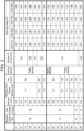
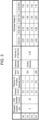
- FIGS. 2-4 are tables showing specifications of examples and comparative examples of lithium primary battery 10.
- positive electrode 201 92 parts by mass of electrolytic manganese dioxide sintered at 400°C for 7 hours was mixed with 3 parts by mass Ketjen Black as a conductive agent, 5 parts by mass of polytetrafluoroethylene as a binder agent, and an appropriate amount of pure water, and the resultant material was kneaded, to prepare a wet positive electrode mixture.
- the et positive electrode mixture fills a positive electrode current collector made of an expanded metal made of stainless steel (SUS 316) to prepare a positive electrode precursor.
- the positive electrode precursor was dried, pressure-rolled with a roll presser, and cut into predetermined dimensions, thereby providing positive electrode 201 having thickness Tp as shown in the tables.
- the filling amount of the positive electrode mixture was adjusted to obtain the designed capacities as shown in the tables.
- the dimensions of positive electrode 201 were adjusted such that the outermost electrode of electrode assembly 200 was positive electrode 201 with negative electrode 202 while total area S of first main surface 202A and second main surface 202B has the values indicated in the tables. However, for Comparative Example 1, the dimensions of positive electrode 201 were adjusted so that the outermost electrode was negative electrode 202.
- Sheet-shaped Li and Li-Al alloy (the Al content with respect to the lithium contained in negative electrode 202: 0.3 mass %) were cut into predetermined dimensions so that total area S of first main surface 202A and second main surface 202B of negative electrode 202 was the value indicated in the tables, to obtain sheet-shaped negative electrode 202.
- the dimensions (width, height, and/or thickness) of the sheet were adjusted such that the amount of Li contained in negative electrode 202 was the same in Examples and Comparative Examples.
- the ratio Cn/Cp of capacity Cn of negative electrode 202 to capacity Cp of positive electrode 201 was about 1.1.
- the positive electrode mixture was peeled off from a part of positive electrode 201 to expose the positive electrode current collector, and a positive electrode tab lead made of stainless steel was resistance welded to the exposed part.
- a negative electrode tab lead made of nickel was connected to a predetermined position on negative electrode 202 by pressure welding.
- Separator 203 was interposed between positive electrode 201 and negative electrode 202. Then, Separator 203, positive electrode 201, and negative electrode 202 were wound in a spiral shape about center axis 200C to prepare a wound body. They were secured with an insulative tape to maintain the wound body, thereby providing wound-electrode assembly 200 having a cylindrical shape.
- positive electrode 201 and negative electrode 202 were stacked such that that total area S of first main surface 202A and second main surface 202B of negative electrode 202 was the values indicated in the tables, and also, separator 203 was disposed such that the outermost electrode was completely covered.
- the outermost electrode of electrode assembly 200 was positive electrode 201 in the examples other than Comparative Example 1.
- the outermost electrode was negative electrode 202 in Comparative Example 1.
- a microporous layer (thickness 40 ⁇ m) having a three-layer structure including a polyethylene microporous layer (intermediate layer: thickness 20 ⁇ m) and two layers of polypropylene microporous layer (outer layer: thickness 10 ⁇ m) that sandwich the intermediate layer.
- Lithium trifluoromethanesulfonate as lithium salt was dissolved into non-aqueous solvent in which propylene carbonate (PC), ethylene carbonate (EC), and 1,2-dimethoxyethane (DME) was mixed in a volume ratio of 1:1:2, at a concentration of 0.5 mol/L to prepare a non-aqueous electrolyte.
- PC propylene carbonate
- EC ethylene carbonate
- DME 1,2-dimethoxyethane
- Electrode assembly 200 was inserted into outer can 100 made of stainless steel (SUS 316) having a closed-end cylindrical shape having outer diameter D and thickness Tc shown in the tables, with a ring-shaped lower insulating plate disposed at the bottom part.
- the positive electrode tab lead was resistance welded to the inner bottom surface of outer can 100, and the upper insulating plate was disposed on the upper part of electrode assembly 200.
- the negative electrode tab lead was resistance welded to external terminal 330 fixed to sealing element 300.
- the non-aqueous electrolyte was put into outer can 100 and electrode assembly 200 is impregnated with the electrolyte.
- sealing element 300 was inserted at opening 501A of outer can 100, and is welded to fitting portions of opening 501A of outer can 100 with laser.
- five samples of hermetically sealed-type cylindrical lithium primary battery 10 that has a structure shown in FIG. 1 were prepared for each of Examples.
- Distance C between outer can 100 and wound-electrode assembly 200 of assembled batteries 10 is shown in the tables.
- Distance C was adjusted by adjusting the thickness and length of each of the electrodes. After that, batteries 10 was subjected to predischarge such that the voltage of each battery 10 became 3.2 V.
- the prepared samples of lithium primary battery 10 were evaluated in discharge voltages at different depths of discharge (DOD) according to the following procedure.
- the samples of lithium primary battery 10 which were preliminary discharged were set to DOD of 0%, and the minimum voltages were measured when they were discharged at -40°C and at 500 mA for 5 seconds. The average of the minimum voltages of 5 samples of lithium primary battery 10 were measured. This average value was used as the discharge voltage at DOD of 0%.
- the samples of lithium primary battery 10 for which the discharge voltage at DOD 0% was obtained were discharged to DOD of 50%, DOD of 75%, and DOD of 85% DOD at 23°C and at 30 mA.
- the minimum voltages of the samples were measured while discharged at -40°C and at 500 mA for 5 seconds in the respective conditions, and the average value was obtained.
- Examples 1 to 16 are samples A1 to A16
- Comparative Examples 1 to 8 are samples B1 to B8, respectively.
- Example B2 and sample B3 show slightly higher discharge voltages at DOD of 75% than at DOD of 50%, but they show even lower discharge voltages at DOD of 85%. Similar tendencies are observed also in the cases where thickness Tp of positive electrode 201 is less than 0.8 or greater than 1.4 mm (samples B4 to B6). In other words, in these examples, the discharge voltage is unstable, and as the discharge progresses, the discharge voltage decreases significantly.
- the discharge voltage dropped significantly as the discharge progressed (sample B 1). This is believed for the following reason. Since positive electrode 201 was not present at the outermost circumference, its alleviating function could not be obtained during discharge. Consequently, reaction unevenness occurred, and the metallic lithium of negative electrode 202 partially broke, increasing the resistance of battery 10. In the case where outer diameter D of outer can 100 exceeds 37 mm or total area S exceeds 700 cm 2 as well, the discharge voltage significantly dropped as the discharge progressed (B7).
- Lithium primary batteries according to the above-described aspects of the present disclosure are capable of exhibiting a high capacity and performing stable discharge, and are suitable for being incorporated in ICT devices that are controlled to discharge pulsed current.
- ICT devices include various devices (such as electronic devices and electric devices) that are equipped with communication functions, such as utility meters equipped with communication functions (such as smart meters). It should be noted, however, that the applications of the lithium primary batteries are not limited to these devices.
Landscapes
- Chemical & Material Sciences (AREA)
- Chemical Kinetics & Catalysis (AREA)
- Electrochemistry (AREA)
- General Chemical & Material Sciences (AREA)
- Engineering & Computer Science (AREA)
- Inorganic Chemistry (AREA)
- Manufacturing & Machinery (AREA)
- Materials Engineering (AREA)
- Primary Cells (AREA)
Abstract
Description
- The present disclosure relates to a lithium primary battery.
- ICT (Information and Communication Technology), including DX (digital transformation) has been accelerated. One of devices that are widely used precedingly in the ICT is, for example, a smart meter. Devices used for such applications may often employ primary batteries as an independent power supply when a power source is not available from electric wires. The primary batteries used for such applications require various performance characteristics such as long life, high capacity, and stable discharge at various currents, from a high pulsed discharge current for communications in ICT to a low current for normal operations. From the viewpoint of ensuring such performance, demand for primary batteries with large capacity increases.
- PTL 1 proposes wound-electrode assembly for a cylindrical non-aqueous electrolyte battery. In wound-electrode assembly, positive and negative electrodes and separators are wound such that the number of windings which is defined by a winding-starting end and a winding-terminating end of a positive electrode including is greater than or equal to 1.0 and less than or equal to 4.0. The positive electrode sheet is obtained by a particular manufacturing method
- PTL 2 proposes that, in a wound-electrode assembly of a cylindrical non-aqueous electrolyte primary battery, a positive electrode with a thickness of greater than or equal to 1.4 mm is used, and 2 sheets of resin microporous films with a thickness of 7 µm to 20 µm are disposed between a positive electrode active material layer and a negative electrode active material layer.
-
PTL 3 proposes the use of a wound-electrode assembly for a lithium primary battery. The wound-electrode assembly uses a positive electrode containing manganese dioxide and a negative electrode containing at least one substance selected from the group consisting of metallic lithium and lithium alloys and having a first main surface and a second main surface opposing the first main surface. The entireties of the first main surface and the second main surface faces the positive electrode. The total area of the first main surface and the second main surface is greater than or equal to 100 cm2 and less than or equal to 180 cm2. -
- PTL 1:
Japanese Patent Unexamined Publication No. 2005-032584 - PTL 2: International Publication No.
2020/054662 - PTL 3: International Publication No.
2020/095500 - In order to ensure a high capacity in a lithium primary battery including a wound-electrode assembly, the size (for example, the diameter) of the battery is increased, or the thicknesses of the electrodes in the wound-electrode assembly is increased. However, the discharging of the lithium primary battery with the outer diameter being large and the thickness of the wound-electrode assembly being great may cause various problems in the portions that face each other. The problems include expansions of the thickness of the positive electrode, decreases in the thickness of the negative electrode, and changes in the thickness of the separators. Consequently, it is difficult to keep the balance of thickness at various parts of the wound-electrode assembly to be uniform. It is also difficult to keep the electrolyte retention amount of the positive electrode and the separator to be uniform. Consequently, it is more likely to cause unevenness in discharge reactions. In particular, the lithium primary battery with a large outer diameter may provide large unevenness in discharge reactions since the number of windings of the electrode assembly is greater and the electrode area is greater.
- More specifically, during discharge, the positive electrode expands, increasing its thickness. On the other hand, the lithium in the negative electrode undergoes dissolution, reducing its thickness. Therefore, as the thickness of the electrodes is greater or the number of windings is greater, the amount of change in thickness during discharge becomes greater, hardly keeping the balance of thickness at the part where the positive electrode and the negative electrode face each other to be uniform to some degree. Consequently, the discharge reaction in the wound-electrode assembly does not undergo uniformly inside, causing differences from one part to another inside the electrode assembly. A separator is inserted between the positive electrode and the negative electrode to provide electrical insulation and retain the electrolyte. The separator has the function of alleviating the stress associated with changes in thickness of the electrodes to a slight degree. However, as the electrodes per se become thicker, the amount of changes in the thickness of the electrodes becomes accordingly greater, exceeding the limit that can be alleviated by the separator. Therefore, the separator is difficult to sufficiently alleviate the stress associated with changes in the thickness of the electrodes. Moreover, when the thickness of the separator changes, the amount of the electrolyte retained by the separators accordingly changes.
- Adverse effects caused by changes in thickness of the electrodes and the separator in the electrode assembly are insignificant at the initial stage of discharge, but as the discharge progresses, adverse effects tend to be more significant. For example, when a high pulsed discharge current for ICT communication is passed at an intermediate level of depth of discharge of 40% to 60%, a large voltage drop may occur, making communication impossible. On the other hand, at a final stage of discharge at an even deeper depth of discharge of 80% to 90%, such a phenomenon may be observed that a voltage drop is small so communication is possible even when a high pulsed discharge current for ICT communication is passed. There is a need for a long life and high capacity lithium primary battery capable of performing stable discharge at various levels of current, from high pulsed discharge currents for ICT communication to low currents for normal operations, irrespective of depth of discharge of the battery.
- A lithium primary battery according to an aspect of the present disclosure includes an outer can, and a wound-electrode assembly and a non-aqueous electrolyte that are accommodated in the outer can. The wound-electrode assembly includes: a positive electrode having a sheet shape; a negative electrode having a sheet shape having a first main surface and a second main surface opposed to each other; and a separator provided between the positive electrode and the negative electrode, the positive electrode, the negative electrode, and the separator being stacked and wound together. The positive electrode includes a positive electrode mixture containing manganese dioxide. The negative electrode includes at least one selected from the group consisting of metallic lithium and metallic lithium containing lithium alloy. The first main surface of the negative electrode and an entirety of the second main surface of the negative electrode face the positive electrode. A total area S of the first main surface and the second main surface of the negative electrode satisfies 250 cm2 ≤ S ≤ 700 cm2. A thickness Tp of the positive electrode satisfies 0.8 mm ≤ Tp ≤ 1.4 mm. An outer diameter D of the outer can satisfies 25 mm ≤ D ≤ 37 mm. A distance C between the outer can and the wound-electrode assembly satisfies 0.3 mm ≤ C ≤ 1.0 mm.
- This lithium primary battery has a large capacity and is stably discharged even when discharge progresses.
-
-
FIG. 1 is a front view of a lithium primary battery according to an exemplary embodiment of the present disclosure for showing a schematic cross section of a part of the lithium primary battery in a vertical direction. -
FIG. 2 shows evaluation results of lithium primary batteries according to the embodiment of the present disclosure. -
FIG. 3 shows evaluation results of lithium primary batteries according to the embodiment of the present disclosure. -
FIG. 4 shows evaluation results of lithium primary batteries according to the embodiment of the present disclosure. -
FIG. 1 is a front view of lithiumprimary battery 10 having a cylindrical shape according to an exemplary embodiment of the present disclosure for showing a schematic cross section of a part of cylindrical lithiumprimary battery 10 in a vertical direction. Lithiumprimary battery 10 is not limited to having a cylindrical shape, but may have a coin shape or a button shape which has a small height in the present invention. - Lithium
primary battery 10 includesouter can 100 has a cylindrical shape with a bottom, wound-electrode assembly 200 accommodated inouter can 100, and sealingelement 300 closing an opening ofouter can 100. Outer can 100 includesside wall 101 having a tubular shape havingopen ends bottom 102 that closes opening 501B atopen end 101B ofside wall 101.Sealing element 300 is fixed toopen end 101A ofouter can 100 by welding.Sealing element 300 closes opening 501A atopen end 101A ofside wall 101 ofouter can 100. An opening is formed at the center of sealingelement 300.External terminal 330 is disposed in the opening.Gasket 310 with an insulating property is disposed betweenexternal terminal 330 and sealingelement 300. - Wound-
electrode assembly 200 includespositive electrode 201 with a sheet shape,negative electrode 202 with a sheet shape, andseparator 203 with a sheet shape provided betweenelectrodes Positive electrode 201,negative electrode 202, andseparator 203 are wound spirally aboutcenter axis 200C.Internal lead wire 210 is connected to one ofpositive electrode 201 and negative electrode 202 (tonegative electrode 202 in the example shown in the figure).Internal lead wire 210 is connected toexternal terminal 330 by, e.g., welding. Anotherinternal lead wire 220 is connected to the other one ofpositive electrode 201 and negative electrode 202 (topositive electrode 201 in the example shown in the figure).Internal lead wire 220 is connected to an inner surface ofouter can 100 by, e.g., welding. -
Negative electrode 202 has firstmain surface 202A and second main surface 202B opposite to firstmain surface 202A. In wound-electrode assembly 200, firstmain surface 202A facescenter axis 200C and second main surface 202B faces outward of wound-electrode assembly 200. The entirety of second main surface 202B ofnegative electrode 202 and firstmain surface 202A facepositive electrode 201 acrossseparator 203. Wound-electrode assembly 200 is accommodated in outer can 100 together withnon-aqueous electrolyte 204. In order to prevent internal short-circuits, upper insulatingplate 230A and lower insulatingplate 230B are disposed at the top and bottom ofelectrode assembly 200, respectively.Electrode assembly 200 facesside wall 101 ofouter can 100 acrossgap 200D with distance C. -
Positive electrode 201 includes a positive electrode mixture containing manganese dioxide.Negative electrode 202 contains at least one substance selected from the group consisting of metallic lithium and metallic lithium containing lithium alloys, and has firstmain surface 202A and second main surface 202B opposite to firstmain surface 202A. Firstmain surface 202A and the entirety of second main surface 202B facepositive electrode 201. In this case, the outermost electrode of theelectrode assembly 200 ispositive electrode 201. For lithiumprimary battery 10, the following conditions (a)-(d) are listed. (a) Total area S of firstmain surface 202A and second main surface 202B ofnegative electrode 202 satisfies 250 cm2 ≤ S ≤ 700 cm2. (b) Thickness Tp ofpositive electrode 201 satisfies 0.8 mm ≤ Tp ≤ 1.4 mm. (c) Outer diameter D ofouter can 100 satisfies 25 mm ≤ D ≤ 37 mm. (d) Distance C betweenouter can 100 and wound-electrode assembly 200 satisfies 0.3 mm ≤ C ≤ 1.0 mm. - PTLs 1-3 specifically describe A-size batteries slightly larger than AA-size, and has outer diameter D of
outer can 100 of about 17 mm. On the other hand, the lithium primary battery of the present disclosure relates to C-size batteries and D-size batteries, and has outer diameter D ofouter can 100 of 25 mm ≤ D ≤ 37 mm. The lithium primary battery of the present disclosure has a larger size than those of PTLs 1-3, about 1.5 times to about 2 times in outer diameter and about 2 times to 4 times in electrode areas. The present inventors discovered that problems that cannot be handled by the batteries with conventional configurations can be resolved by combining the above-mentioned four conditions (a)-(d) simultaneously. - The area of
negative electrode 202 contributes to discharge characteristics of the battery more than the area ofpositive electrode 201. First, an effective range of the total area S ofmain surfaces 202A and 202B ofnegative electrode 202 is determined, and then, the range of thickness Tn ofnegative electrode 202 that yields the effect is determined based on the area ofnegative electrode 202 that is a half of the total area S ofnegative electrode 202 and the specific gravity of constituting components ofnegative electrode 202. Thickness Tp ofpositive electrode 201 satisfying 0.8 mm ≤ Tp ≤ 1.4 mm optimizes the configuration of wound-electrode assembly 200.Negative electrode 202 with total area S less than 250 cm2 provides low discharge current for normal operations, but cannot provide high pulse discharge current for ICT communications.Negative electrode 202 with total area S greater than 700 cm2 reduces the current collecting efficiently, hardly providing high current for ICT communications, and has large secondary materials, such asseparator 203, accordingly reducing energy density.Positive electrode 201 with thickness Tp smaller than 0.8 mm hardly balances the compensation for the thickness decrease ofnegative electrode 202 during discharge by the expansion ofpositive electrode 201, hence tending to impair the stability of discharge at various depth of discharge.Positive electrode 201 with thickness Tp greater than 1.4 mm has an excessive large expansion, and may conversely accelerate reaction ofnegative electrode 202 during discharge, so it is unable to obtain a discharge capacity for a predetermined preparation amount. Moreover, the difference between the maximum outer diameter and the minimum outer diameter ofelectrode assembly 200 itself becomes even larger, which means that the cross section becomes farther different from a perfect circle, so that it may be impossible to achieve high density. - Distance C between wound-
electrode assembly 200 and outer can 100 with outer diameter D of 25 mm ≤ D ≤ 37 mm satisfies 0.3 mm ≤ C ≤ 1.0 mm. In the initial discharge state, distance C between wound-electrode assembly 200 and outer can 100 is extremely important. Since wound-electrode assembly 200 does not have a perfect cylindrical shape, but has a maximum outer diameter and a minimum outer diameter, so that distance C may be within a range of 0.3 mm ≤ C ≤ 1.0 mm based on the maximum outer diameter. Distance C may preferably be within a range of 0.4 mm ≤ C ≤ 0.9 mm. If the battery has a portion with distance C less than 0.3 mm, portions of the battery with distance C of zero or wound-electrode assembly 200 presses and contact the inner surface ofouter can 100 when discharge progresses to an intermediate level. As a consequence, the effect due to the pressure ofouter can 100 on the condition ofelectrode assembly 200 during discharge becomes significant, and reaction unevenness is likely to occur. Distance C greater than 1.0 mm provides a gap betweenouter can 100 and the internal surface at a lot of portions ofelectrode assembly 200 until the final stage of discharge, andelectrode assembly 200 is not affected by the pressure due to outer can 100 at all, so that discharge becomes unstable at the final stage of discharge. - In the configurations, lithium
primary battery 10 according to the present disclosure provides the following advantageous effects. Since firstmain surface 202A and the entirety of second main surface 202B ofnegative electrode 202 facepositive electrode 201, the outermost electrode out of the electrodes of wound-electrode assembly 200 (in other words, the outermost electrode) ispositive electrode 201. As discharge proceeds, wound-electrode assembly 200 expands in radial directions, causing the inner surface ofouter can 100 to contact the outer circumference of wound-electrode assembly 200. Since the outermost circumference of the electrodes of wound-electrode assembly 200 ispositive electrode 201,positive electrode 201 andseparator 203 cover lithium innegative electrode 202. Accordingly, whenpositive electrode 201 expands andelectrode assembly 200 contacts the inner surface ofouter can 100, the expansion ofpositive electrode 201 is directed inward rather than outward because of the reaction force ofouter can 100. As a result, the thickness decrease due to discharge ofnegative electrode 202 is compensated and balanced, and reduces the stress due to the expansion ofelectrode assembly 200. Therefore, the battery has stable performance characteristics until the final stage of discharge irrespective of the depth of discharge. On the other hand, if the area ofnegative electrode 202 is large and the outermost circumference of the electrodes of wound-electrode assembly 200 isnegative electrode 202, the pressure due to the expansion ofpositive electrode 201 associated with the progress of discharge is directed outward, so thatnegative electrode 202 may be easily cut off around the outermost end which is a terminated end of windings ofpositive electrode 201. Consequently, a predetermined estimated amount of discharge capacity is not obtained, thus hardly solving the problems. - Thickness Tp of
positive electrode 201, distance C, and total area S ofnegative electrode 202 are values at the initial stage of discharge of lithiumprimary battery 10. In the present description, lithiumprimary battery 10 at the initial stage of discharge means lithiumprimary battery 10 having a depth of discharge (hereinafter referred to as "DOD") less than or equal to 10%. For stabilizing characteristics, lithiumprimary battery 10 is slightly discharged after fabrication ofbattery 10 to reduce the battery voltage from about 3.6 V to about 3.2 V. The slight discharge is referred to as a predischarge. The unused products (at the time of shipment) of lithiumprimary battery 10 that have undergone predischarge are in a state of DOD of 0%. As long as lithiumprimary battery 10 has the DOD less than or equal to 10%, not just in the unused state, it may be considered that the values defined for lithiumprimary battery 10 at the initial stage of discharge in the present description are not affected. The DOD of 100% means the discharge capacity (i.e., rated discharge capacity, design capacity) whenbattery 10 is discharged at a rated discharge current (for example, at a current greater than or equal to 1 mA and less than or equal to 5 mA) and the voltage ofbattery 10 reaches 2 V. Although the rated current depends on the size or capacity ofbattery 10, a rated current less than or equal to a certain value results in no difference in the resulting discharge capacity. The discharge capacity at DOD of 100% based on the rated current used as reference, to calculate the discharge capacity at each DOD. -
Negative electrode 202 has a sheet shape having two main surfaces occupies most of the surfaces ofnegative electrode 202. One of the main surfaces is firstmain surface 202A, and the main surface opposite to firstmain surface 202A (in other words, the other main surface) is second main surface 202B.Negative electrode 202 having the sheet shape has end surface 202C connected to firstmain surface 202A and second main surface 202B other than firstmain surface 202A and second main surface 202B. The area of each main surface means the projected area of each main surface in a sheet thickness direction when the sheet is laid in a flat state. In the case that the electrode has a part of each main surface containing neither metallic lithium nor metallic lithium containing a lithium alloy, the area of the part is excluded in calculating the area of each main surface. Total area S of firstmain surface 202A and second main surface 202B does not include the area of end surface 202C. Total area S ofmain surfaces 202A and 202B is substantially the area of the portions of the surfaces ofnegative electrode 202 that facepositive electrode 201. - Distance C is the difference between the maximum diameter of wound-
electrode assembly 200 and inner diameter Dd ofside wall 101 at a portion ofouter can 100 accommodating wound-electrode assembly 200 therein. Inner diameter Dd ofouter can 100 is the average of inner diameters Dd measured at plural positions (for example, three positions at angular positions of every 60°) along the inner circumferential surface ofside wall 101 ofouter can 100 at the midpoint in a height direction alongcenter axis 200C ofelectrode assembly 200 in lithiumprimary battery 10. The maximum diameter ofelectrode assembly 200 is the maximum diameter ofelectrode assembly 200 at the midpoint ofelectrode assembly 200 in the height direction. The maximum diameter ofelectrode assembly 200 is measured on the outermost circumferential surface ofelectrode assembly 200. In the case that the outermost circumference ofelectrode assembly 200 isseparator 203, the maximum diameter ofelectrode assembly 200 is determined includingseparator 203 at the outermost circumference. - Outer diameter D of
side wall 101 ofouter can 100 is the average of the outer diameters measured at plural positions (for example, three positions at angular positions of every 60°) along the outer circumferential surface ofside wall 101 ofouter can 100 at the midpoint ofouter can 100 in the height direction in lithiumprimary battery 10. - A configuration of cylindrical lithium
primary battery 10 according to the foregoing aspect will be detail below. - The positive electrode active material may be made of manganese dioxide alone or may be made of mixture of manganese dioxide with, e.g., manganese oxide or graphite fluoride. The manganese dioxide is preferably electrolytic manganese dioxide neutralized with, e.g., ammonia, sodium, or lithium. The manganese dioxide is preferably made of sintered electrolytic manganese dioxide. Specifically, the electrolytic manganese dioxide may be preferably sintered in air or in oxygen at a temperature ranging from 300°C to 450°C for about 6-12 hours. The oxidation number of manganese contained in the manganese dioxide is typically 4; but the oxidation number is not limited to 4, and may be a smaller number. Examples of usable manganese dioxides include MnO, Mn3O4, Mn2O3, and MnO2, and generally, manganese dioxide is used as a main component. Manganese dioxide may be in a mixed crystal state, in which plural types of crystals are contained. In the case that non-sintered electrolytic manganese dioxide is used, it is preferable to use a manganese dioxide in which the degree of crystallinity is increased by conditions in electrolytic synthesis to reduce the specific surface area. In addition, it is possible to add chemical manganese dioxide or the like, if the amount is small.
-
Positive electrode 201 further includes a positive electrode current collector in addition to the positive electrode mixture.Positive electrode 201 may include a positive electrode mixture layer. - Thickness Tp of
positive electrode 201 satisfies 0.8 mm ≤ Tp ≤ 1.4 mm. Thickness Tp may satisfy 1.0 mm ≤ Tp ≤ 1.3 mm, or 1.1 mm ≤ Tp ≤ 1.3 mm from the viewpoint that it is easier to provide a higher capacity and a higher discharge voltage even when discharge progresses. - Thickness Tp of
positive electrode 201 is the average of the thicknesses measured at plural positions (for example, ten positions) onpositive electrode 201 included inelectrode assembly 200 in lithiumprimary battery 10 at an initial stage of discharge. Thickness Tp ofpositive electrode 201 is measured on a cross-sectional image perpendicular to the axial direction ofelectrode assembly 200 of lithiumprimary battery 10. The cross-sectional image may be obtained by, for example, X-ray radiography or X-ray computed tomography (CT). - In addition to the positive electrode active material, the positive electrode mixture contains, for example, binder agent and conductive agent as optional components.
- Examples of the binder agent include fluoropolymers, polyacrylonitriles, polyimide resins, acrylic resins, polyolefins, and rubbery polymers. The positive electrode mixture may contain one type of binder agent or two or more types of binder agents.
- A preferable example the conductive agent is a carbon material. Examples of the carbon material include carbon black, carbon nanotube, and graphite. The positive electrode mixture may contain one type of conductive agent or two or more types of conductive agents. The conductive agent may be allowed to be present between a positive electrode current collector and a positive electrode mixture layer.
- Density dp of the positive electrode mixture satisfies, for example, 2.5 g/cm3 ≤ dp ≤ 3.5 g/cm3. Density dp may preferably satisfy 2.6 g/cm3 ≤ dp ≤ 3.3 g/cm3 from the viewpoint that it is even easier to stabilize the discharge voltage against the expansion of
positive electrode 201 when absorbing the electrolyte or during discharge and against the thinning ofnegative electrode 202 due to dissolution. - Density dp of the positive electrode mixture may be obtained based on thickness Tp of
positive electrode 201 and the mass and volume of the positive electrode mixture excluding the current collector afterpositive electrode 201 is removed from lithiumprimary battery 10 at the initial stage of discharge, washed with a solvent, and dried. - Examples of the material for the positive electrode current collector include metallic materials, such as stainless steel, Al, and Ti. The metallic materials may be either a metal alone or alloys. Examples of the positive electrode current collector include sheets and porous materials. The positive electrode current collector may be a metal foil. The positive electrode current collector may be, e.g., a porous positive electrode current collector, a metallic mesh, an expanded metal, or a punched metal.
- A method of manufacturing
positive electrode 201 is not particularly limited. To fabricatepositive electrode 201, a positive electrode mixture may be applied onto a positive electrode current collector, or a positive electrode mixture may fill a porous positive electrode current collector. Alternatively, a positive electrode mixture may have a sheet shape and stacked on the positive electrode current collector so as to physically contact the positive electrode current collector. In fabricatingpositive electrode 201, the positive electrode mixture may be used in a paste form or in a clay form, as needed, using a liquid medium in addition to the constituting components of the positive electrode mixture. Examples of the liquid medium include water and organic liquid media. The liquid medium may be in a liquid state at, e.g., room temperature (20-35°C). At an appropriate stage of manufacture,positive electrode 201 may be dried as needed, orpositive electrode 201 may also be compressed in a thickness direction ofpositive electrode 201. -
Negative electrode 202 contains at least one metallic material selected from the group consisting of metallic lithium and metallic lithium containing lithium alloys. Examples of the lithium alloys include Li-Al, Li-Sn, Li-Ni-Si, and Li-Pb. The content of the metallic elements other than lithium that are contained in the lithium alloy is, for example, greater than or equal to 0.05 mass% and less than or equal to 1.0 mass% with respect to the lithium alloy. -
Negative electrode 202 with the sheet shape may be made of, e.g., a metal foil.Negative electrode 202 with the sheet shape may be formed by extrusion molding the metallic materials described above. - A tape or the like may be affixed to a part of
negative electrode 202 with the sheet shape so as to preventnegative electrode 202 from being consumed and isolated accordingly during discharge. The width of the tape is preferably greater than or equal to 0.5 mm to less than or equal to 3 mm so as not to suppressing battery reaction. The tape may be affixed to either one or both of firstmain surface 202A and second main surface 202B ofnegative electrode 202 with the sheet shape. - In the present disclosure, first
main surface 202A and the entirety of second main surface 202B ofnegative electrode 202 facepositive electrode 201. This configuration allowspositive electrode 201 to be an electrode that is located at the outermost circumference of wound-electrode assembly 200. - Capacity Cn of
negative electrode 202 and capacity Cp ofpositive electrode 201 preferably satisfy Cp ≤ Cn. Since unreacted lithium remains even at the final stage of discharge and maintains the thickness ofnegative electrode 202 to some degree, reaction unevenness is reduced as an advantageous effect onnegative electrode 202 side. The ratio Cn/Cp of capacity Cn ofnegative electrode 202 to capacity Cp ofpositive electrode 201 may be preferably greater than 1, and may be, for example, greater than or equal to 1.05, or greater than or equal to 1.10. the ratio Cn/Cp is preferably less than or equal to 1.2 so as to provide a sufficiently high energy density. - Capacity Cn and capacity Cp may be obtained by the following procedure.
Positive electrode 201 is removed from lithiumprimary battery 10 at the initial stage of discharge, and the mass of manganese dioxide contained inpositive electrode 201 is obtained.Negative electrode 202 is removed from lithiumprimary battery 10 at the initial stage of discharge, and the mass of metallic lithium contained innegative electrode 202 is obtained. Based on the mass of manganese dioxide and the theoretical capacity of manganese dioxide (308 mAh/g), capacity Cp is obtained. Based on the mass of metallic lithium contained innegative electrode 202 and the theoretical capacity of lithium (3860 mAh/g), capacity Cn is obtained. - Total area S of first
main surface 202A and second main surface 202B ofnegative electrode 202 satisfies 250 cm2 ≤ S ≤ 700 cm2. Total area S preferably is within the range of 265 cm2 ≤ S ≤ 680 cm2, more preferably 300 cm2 ≤ S ≤ 500 cm2. So as to obtain a high discharge voltage and a high capacity -
Separator 203 is made of a porous sheet having ion-permeability and insulative property. Examples of the porous sheet include microporous films, woven fabrics, and nonwoven fabrics.Separator 203 may be either a single-layer structure or a multi-layer structure. An example ofseparator 203 having a multi-layer structure isseparator 203 including plural layers that are different in at least one of material or structure. Inseparator 203 having a multi-layer structure with three or more layers, some of the layers (for example, two layers) may be the same in material and structure, or all the layers may be different in at least one of material or structure. - Examples of the material for
separator 203 include polymer materials. Examples of the polymer materials include olefin resins, polyamide resins, polyimide resins (such as polyimides and polyamide imides), celluloses, polyphenylene sulfides, and polytetrafluoroethylenes.Separator 203 may further contain an additive as needed. Examples of the additive include inorganic fillers and the like. - Thickness Ts of
separator 203 may be selected from the range greater than or equal to 10 µm to less than or equal to 200 µm. Whenseparator 203 is made of a microporous film, thickness Ts ofseparator 203 may be, for example, greater than or equal to 10 µm to less than or equal to 80 µm. Thickness Ts ofseparator 203 made of a microporous film is preferably greater than or equal to 30 µm and less than or equal to 50 µm so as to reduce the internal resistance and obtain a higher discharge voltage easily even when discharge progresses. In the case tharseparator 203 contains nonwoven fabric, thickness Ts ofseparator 203 may be selected from the range greater than or equal to 100 µm to less than or equal to 200 µm. A microporous film and a nonwoven fabric may be combined together to provide the separator. - Wound-
electrode assembly 200 is formed by spirally windingnegative electrode 202,positive electrode 201, andseparator 203 interposed between the electrodes.Negative electrode 202 andpositive electrode 201 are disposed withseparator 203 interposed between the electrodes such that the entirety of second main surface 202B and firstmain surface 202A of thenegative electrode 202 facepositive electrode 201. - The maximum diameter of wound-
electrode assembly 200 is obtained forelectrode assembly 200 removed from lithiumprimary battery 10 at the initial stage of discharge. More specifically, diameters are measured along the outermost circumferential surface at plural positions (for example, six positions) in directions perpendicular to the winding axis, and the maximum value among the measured diameters is regarded as the maximum diameter ofelectrode assembly 200. The diameter ofelectrode assembly 200 is measured with, e.g., a vernier caliper. -
Non-aqueous electrolyte 204 in lithiumprimary battery 10 has lithium ion conductivity. Suchnon-aqueous electrolyte 204 contains a non-aqueous solvent and a lithium salt dissolved in the non-aqueous solvent. - Examples of the lithium salt include lithium fluoroborate, lithium hexafluorophosphate, lithium trifluoromethanesulfonate, lithium bis(fluorosulfonyl)imide, lithium bis(trifluoromethylsulfonyl)imide, and lithium perchlorate.
Non-aqueous electrolyte 204 may contain one type of lithium salt, or two or more types of lithium salts in combination. - Examples of the non-aqueous solvent include, but are not limited to, esters (for example, carbonic esters, carboxylic esters such as γ-butyrolactone) and ethers (such as 1,2-dimethoxyethane). Examples of the carbonic esters include cyclic carbonates (such as propylene carbonate and ethylene carbonate) and chain carbonates (such as dimethyl carbonate and methyl ethyl carbonate).
Non-aqueous electrolyte 204 may contain one type of non-aqueous solvent, or two or more types of non-aqueous solvents in combination. - The concentration of lithium salt in
non-aqueous electrolyte 204 is, for example, greater than or equal to 0.1 mol/L and less than or equal to 3.5 mol/L. -
Non-aqueous electrolyte 204 may further contain additive as needed. Examples of the additive include vinylene carbonate, fluoroethylene carbonate, and vinylethyl carbonate.Non-aqueous electrolyte 204 may contain one type of additive, or two or more types of additives in combination. - Outer can 100 is made of stainless steel, iron, aluminum, or an aluminum alloy. Each of the materials satisfies the strength to prevent deformation of
outer can 100 even whenpositive electrode 201 expands, to reduce variations in discharge reactions, and to stabilize the discharge voltage even when discharge progresses. Outer can 100 may be processed with annealing or plating, as needed. In addition, outer can 100 made of stainless steel has high durability that withstands a long-term use. - Thickness Tc of
outer can 100 is preferably greater than or equal to 0.25 mm. Thickness Tc is preferably 0.3 mm ≤ Tc ≤ 0.45 mm for discharge stability and energy density - Thickness Tc of
outer can 100 is the average of the thicknesses measured at plural positions (for example, six positions at every 60°) along the inner circumferential surface ofouter can 100 at the midpoint in a height direction ofelectrode assembly 200 of lithiumprimary battery 10. Thickness Tc ofouter can 100 is measured on a cross-sectional image perpendicular to a direction alongcenter axis 200C ofelectrode assembly 200 of lithiumprimary battery 10. - Inner diameter Dd of
side wall 101 ofouter can 100 may be measured on a cross-sectional image perpendicular to the direction ofcenter axis 200C ofelectrode assembly 200 of lithiumprimary battery 10. Distance C is obtained from inner diameter Dd (average value) ofouter can 100 and the maximum diameter ofelectrode assembly 200 that are determined as described above. - According to the above-described aspect of the present disclosure, the polarity of
outer can 100 may be eitherpositive electrode 201 ornegative electrode 202. In the present disclosure, basically, two types of configurations are possible for the outermost circumference of wound-electrode assembly 200. The first one is a configuration in which separator 203 completely covers the outermost electrode,positive electrode 201, and in addition, a tape is affixed to a portion of the outermost circumference onseparator 203 so that the winding state can be maintained. The second one is a configuration in which the outermost electrode,positive electrode 201, is not completely covered withseparator 203 so thatseparator 203 does not exist partially or not at all on the outermost electrode, and a tape is affixed to a portion of the outermost electrode to maintain the winding state. Regardless of the polaritiesouter can 100, the combination of a tape andseparator 203 that completely covers the outermost electrode,positive electrode 201 is preferable from the viewpoint of reducing the risk of internal short circuits resulting from excessive physical vibrations or dropping, separation of the electrode mixture from the electrodes, electrode deformations, or the like. Sinceseparator 203 or the tape may have failures due to external impacts or the like, the polarity may preferably be matched betweenouter can 100 and the outermost electrode by making outer can 100 to bepositive electrode 201 and the outermost electrode to bepositive electrode 201 so as to reduce the risk of internal short circuits. Outer can 100 and the electrode having the same polarity may contact each other with pressure. However, an insulative coating may preferably be provided on the inner surface ofouter can 100 so as to reduce the risk of internal short circuits. - Lithium
primary battery 10 may include sealingelement 300 that seals opening 501A ofouter can 100.Sealing element 300 is made of stainless steel, iron, aluminum, or aluminum alloy.Sealing element 300 may be preferably made of stainless steel so as to easily provide sufficient durability and strength.Sealing element 300 may be processed with annealing or plating, as needed. - Each of
outer can 100 and sealingelement 300 may be electrically connected to either one ofpositive electrode 201 andnegative electrode 202 ofelectrode assembly 200. Opening 501A ofouter can 100 may be sealed by press-fittingopen end 101A ofouter can 100 to the circumferential edge of sealingelement 300, or by laserwelding sealing element 300 to the circumferential edge of opening 501A ofouter can 100. In the case that the sealing is performed by the former way,insulative gasket 310 is disposed betweenopen end 101A ofouter can 100 and the circumferential edge of sealingelement 300. In the case that the sealing is performed by the latter way, sealingelement 300 andexternal terminal 330 are prepared as separate members andinsulative gasket 310 is disposed betweenexternal terminal 330 and sealingelement 300. For applications that require a long expected life, sealingelement 300 is welded to openend 101A ofouter can 100 with laser. This is advantageous for ensuring a longer life since the adverse effects resulting from the entry of the air intobattery 10 or the volatilization ofnon-aqueous electrolyte 204 can be reduced. The adverse effects resulting from the entry of the air or the volatilization ofnon-aqueous electrolyte 204 result in a multiplier of the number of years of use, so that the adverse effects are believed to be greater as the number of years of use becomes longer. - Lithium
primary battery 10 according to the above-described aspect of the present disclosure has a high capacity and is capable of stable discharge even when discharge progresses. In addition, the battery delivers a high output power and provides a relatively high discharge voltage even when discharge progresses. Therefore, the battery has a long life and also has discharge performance of high current, such as pulsed current, over a long term. For these reasons, lithiumprimary battery 10 is suitable for being incorporated in devices that are controlled to discharge pulsed current over a long term. Examples of such devices include, but are not limited to, utility meters for ICT equipped with communication functions (for example, utility meters equipped with communication functions). Examples of the utility meters include various utility meters, such as electricity meters, gas meters, and water meters. - The present disclosure will be detailed below with reference to the following examples and comparative examples. However, the present invention is not limited to the following examples.
FIGS. 2-4 are tables showing specifications of examples and comparative examples of lithiumprimary battery 10. - To prepare
positive electrode 201, 92 parts by mass of electrolytic manganese dioxide sintered at 400°C for 7 hours was mixed with 3 parts by mass Ketjen Black as a conductive agent, 5 parts by mass of polytetrafluoroethylene as a binder agent, and an appropriate amount of pure water, and the resultant material was kneaded, to prepare a wet positive electrode mixture. - Next, the et positive electrode mixture fills a positive electrode current collector made of an expanded metal made of stainless steel (SUS 316) to prepare a positive electrode precursor. After that, the positive electrode precursor was dried, pressure-rolled with a roll presser, and cut into predetermined dimensions, thereby providing
positive electrode 201 having thickness Tp as shown in the tables. The filling amount of the positive electrode mixture was adjusted to obtain the designed capacities as shown in the tables. The dimensions ofpositive electrode 201 were adjusted such that the outermost electrode ofelectrode assembly 200 waspositive electrode 201 withnegative electrode 202 while total area S of firstmain surface 202A and second main surface 202B has the values indicated in the tables. However, for Comparative Example 1, the dimensions ofpositive electrode 201 were adjusted so that the outermost electrode wasnegative electrode 202. - Sheet-shaped Li and Li-Al alloy (the Al content with respect to the lithium contained in negative electrode 202: 0.3 mass %) were cut into predetermined dimensions so that total area S of first
main surface 202A and second main surface 202B ofnegative electrode 202 was the value indicated in the tables, to obtain sheet-shapednegative electrode 202. The dimensions (width, height, and/or thickness) of the sheet were adjusted such that the amount of Li contained innegative electrode 202 was the same in Examples and Comparative Examples. - The ratio Cn/Cp of capacity Cn of
negative electrode 202 to capacity Cp ofpositive electrode 201 was about 1.1. - The positive electrode mixture was peeled off from a part of
positive electrode 201 to expose the positive electrode current collector, and a positive electrode tab lead made of stainless steel was resistance welded to the exposed part. A negative electrode tab lead made of nickel was connected to a predetermined position onnegative electrode 202 by pressure welding.Separator 203 was interposed betweenpositive electrode 201 andnegative electrode 202. Then,Separator 203,positive electrode 201, andnegative electrode 202 were wound in a spiral shape aboutcenter axis 200C to prepare a wound body. They were secured with an insulative tape to maintain the wound body, thereby providing wound-electrode assembly 200 having a cylindrical shape. At this moment,positive electrode 201 andnegative electrode 202 were stacked such that that total area S of firstmain surface 202A and second main surface 202B ofnegative electrode 202 was the values indicated in the tables, and also,separator 203 was disposed such that the outermost electrode was completely covered. The outermost electrode ofelectrode assembly 200 waspositive electrode 201 in the examples other than Comparative Example 1. The outermost electrode wasnegative electrode 202 in Comparative Example 1. - For
separator 203, a microporous layer (thickness 40 µm) having a three-layer structure including a polyethylene microporous layer (intermediate layer: thickness 20 µm) and two layers of polypropylene microporous layer (outer layer:thickness 10 µm) that sandwich the intermediate layer. - Lithium trifluoromethanesulfonate as lithium salt was dissolved into non-aqueous solvent in which propylene carbonate (PC), ethylene carbonate (EC), and 1,2-dimethoxyethane (DME) was mixed in a volume ratio of 1:1:2, at a concentration of 0.5 mol/L to prepare a non-aqueous electrolyte.
-
Electrode assembly 200 was inserted into outer can 100 made of stainless steel (SUS 316) having a closed-end cylindrical shape having outer diameter D and thickness Tc shown in the tables, with a ring-shaped lower insulating plate disposed at the bottom part. The positive electrode tab lead was resistance welded to the inner bottom surface ofouter can 100, and the upper insulating plate was disposed on the upper part ofelectrode assembly 200. After that, the negative electrode tab lead was resistance welded toexternal terminal 330 fixed to sealingelement 300. Next, the non-aqueous electrolyte was put intoouter can 100 andelectrode assembly 200 is impregnated with the electrolyte. After that, sealingelement 300 was inserted at opening 501A ofouter can 100, and is welded to fitting portions of opening 501A ofouter can 100 with laser. Thus, five samples of hermetically sealed-type cylindrical lithiumprimary battery 10 that has a structure shown inFIG. 1 were prepared for each of Examples. Distance C betweenouter can 100 and wound-electrode assembly 200 of assembledbatteries 10 is shown in the tables. Distance C was adjusted by adjusting the thickness and length of each of the electrodes. After that,batteries 10 was subjected to predischarge such that the voltage of eachbattery 10 became 3.2 V. - The prepared samples of lithium
primary battery 10 were evaluated in discharge voltages at different depths of discharge (DOD) according to the following procedure. - The samples of lithium
primary battery 10 which were preliminary discharged were set to DOD of 0%, and the minimum voltages were measured when they were discharged at -40°C and at 500 mA for 5 seconds. The average of the minimum voltages of 5 samples of lithiumprimary battery 10 were measured. This average value was used as the discharge voltage at DOD of 0%. - The samples of lithium
primary battery 10 for which the discharge voltage atDOD 0% was obtained were discharged to DOD of 50%, DOD of 75%, and DOD of 85% DOD at 23°C and at 30 mA. The minimum voltages of the samples were measured while discharged at -40°C and at 500 mA for 5 seconds in the respective conditions, and the average value was obtained. - The evaluation results for Examples and Comparative Examples are shown in
FIGS. 2 to 4 . Examples 1 to 16 are samples A1 to A16, and Comparative Examples 1 to 8 are samples B1 to B8, respectively. - As shown in
FIG. 2 , a drop of discharge voltage is observed at DOD of 50% in the cases where distance C is less than 0.3 mm or exceeds 1.0 mm (sample B2 and sample B3). Samples B2 and B3 show slightly higher discharge voltages at DOD of 75% than at DOD of 50%, but they show even lower discharge voltages at DOD of 85%. Similar tendencies are observed also in the cases where thickness Tp ofpositive electrode 201 is less than 0.8 or greater than 1.4 mm (samples B4 to B6). In other words, in these examples, the discharge voltage is unstable, and as the discharge progresses, the discharge voltage decreases significantly. It is believed that such results were observed since unevenness in discharge reactions occurred in samples B2, B3, B5, and B6 because of large variations in the distribution ofelectrolyte 204. In addition, it is believed that in these Comparative Examples, the discharge voltage dropped at 50% DOD because it is difficult to keep a balance between the expansion ofpositive electrode 201 and the contraction ofnegative electrode 202. Sample B6 is an example in which total area S of firstmain surface 202A and second main surface 202B is small, but it is believed that the discharge voltage was relatively low from the initial stage because its reaction aera is small. - In contrast to the above results of Comparative Examples, in the cases where distance C satisfies 0.3 mm ≤ C ≤ 1.0 mm and thickness Tp of
positive electrode 201 satisfies 0.8 mm ≤ Tp ≤ 1.4 mm, no drop of the discharge voltage at DOD of 50% was observed, and relatively high discharge voltage was maintained even at DOD of 85% (samples A1-A7). - In the case where the first
main surface 202A and the entirety of the second main surface 202B do not face positive electrode 201 (i.e., the outermost electrode ofelectrode assembly 200 is negative electrode 202), the discharge voltage dropped significantly as the discharge progressed (sample B 1). This is believed for the following reason. Sincepositive electrode 201 was not present at the outermost circumference, its alleviating function could not be obtained during discharge. Consequently, reaction unevenness occurred, and the metallic lithium ofnegative electrode 202 partially broke, increasing the resistance ofbattery 10. In the case where outer diameter D ofouter can 100 exceeds 37 mm or total area S exceeds 700 cm2 as well, the discharge voltage significantly dropped as the discharge progressed (B7). This is believed to be that, because the length of the electrodes was excessively great, broken locations innegative electrode 202 increased as the discharge progressed. In the case where outer diameter D ofouter can 100 is less than 25 mm or total area S is less than 250 cm2, the discharge voltage significantly dropped as the discharge progressed (sample B8). This is believed to be because it was difficult to provide an electrode area sufficient for performing discharge reactions. - As shown in
FIGS. 3 and4 , in the cases where outer diameter D ofouter can 100 is 25 mm or 37 mm, no drop of discharge voltage at 50% DOD was observed, and a relatively high discharge voltage was obtained even when the discharge progresses, as in the cases of samples A1 to A7. - Lithium primary batteries according to the above-described aspects of the present disclosure are capable of exhibiting a high capacity and performing stable discharge, and are suitable for being incorporated in ICT devices that are controlled to discharge pulsed current. Examples of such devices include various devices (such as electronic devices and electric devices) that are equipped with communication functions, such as utility meters equipped with communication functions (such as smart meters). It should be noted, however, that the applications of the lithium primary batteries are not limited to these devices.
-
- 10
- lithium primary battery
- 100
- outer can
- 200
- wound-electrode assembly
- 201
- positive electrode
- 202
- negative electrode
- 203
- separator
- 204
- non-aqueous electrolyte
- 210
- internal lead wire
- 230A
- upper insulating plate
- 230B
- lower insulating plate
- 300
- sealing element
- 310
- gasket
- 330
- external terminal
Claims (7)
- A lithium primary battery comprising:an outer can;a wound-electrode assembly accommodated in the outer can; anda non-aqueous electrolyte accommodated in the outer can, whereinthe wound-electrode assembly includes:a positive electrode having a sheet shape;a negative electrode having a sheet shape having a first main surface and a second main surface opposed to each other; anda separator provided between the positive electrode and the negative electrode, the positive electrode, the negative electrode, and the separator being stacked and wound together,the positive electrode includes a positive electrode mixture containing manganese dioxide,the negative electrode includes at least one selected from the group consisting of metallic lithium and metallic lithium containing lithium alloy,the first main surface of the negative electrode and an entirety of the second main surface of the negative electrode face the positive electrode,a total area S of the first main surface and the second main surface of the negative electrode satisfies 250 cm2 ≤ S ≤ 700 cm2,a thickness Tp of the positive electrode satisfies 0.8 mm ≤ Tp ≤ 1.4 mm,an outer diameter D of the outer can satisfies 25 mm ≤ D ≤ 37 mm, anda distance C between the outer can and the wound-electrode assembly satisfies 0.3 mm ≤ C ≤ 1.0 mm.
- The lithium primary battery according to claim 1, wherein a thickness Tc of the outer can satisfies 0.3 mm ≤ Tc ≤ 0.45 mm.
- The lithium primary battery according to claim 1 or 2, wherein a capacity Cp of the positive electrode and a capacity Cn of the negative electrode satisfy Cp ≤ Cn.
- The lithium primary battery according to any one of claims 1 to 3, wherein a density dp of the positive electrode mixture satisfies 2.6 g/cm3 ≤ dp ≤ 3.3 g/cm3.
- The lithium primary battery according to any one of claims 1 to 4, wherein the separator is made of a microporous film having a thickness greater than or equal to 30 µm to less than or equal to 50 µm.
- The lithium primary battery according to any one of claims 1 to 5, further comprisinga sealing element sealing an opening of the outer can,wherein the sealing element is laser-welded to the outer can.
- The lithium primary battery according to any one of claims 1 to 6, wherein the outer can is made of stainless steel.
Applications Claiming Priority (2)
| Application Number | Priority Date | Filing Date | Title |
|---|---|---|---|
| JP2021091816 | 2021-05-31 | ||
| PCT/JP2022/018114 WO2022254983A1 (en) | 2021-05-31 | 2022-04-19 | Lithium primary battery |
Publications (2)
| Publication Number | Publication Date |
|---|---|
| EP4350797A1 true EP4350797A1 (en) | 2024-04-10 |
| EP4350797A4 EP4350797A4 (en) | 2025-04-23 |
Family
ID=84323080
Family Applications (1)
| Application Number | Title | Priority Date | Filing Date |
|---|---|---|---|
| EP22815739.2A Pending EP4350797A4 (en) | 2021-05-31 | 2022-04-19 | LITHIUM PRIMARY BATTERY |
Country Status (5)
| Country | Link |
|---|---|
| US (1) | US20240250284A1 (en) |
| EP (1) | EP4350797A4 (en) |
| JP (1) | JP7617539B2 (en) |
| CN (1) | CN117378066A (en) |
| WO (1) | WO2022254983A1 (en) |
Family Cites Families (9)
| Publication number | Priority date | Publication date | Assignee | Title |
|---|---|---|---|---|
| JP2002042742A (en) * | 2000-07-31 | 2002-02-08 | Toyota Central Res & Dev Lab Inc | Manufacturing method of sealed battery |
| JP4151840B2 (en) | 2003-07-07 | 2008-09-17 | 日立マクセル株式会社 | Non-aqueous electrolyte battery |
| JP2005108645A (en) * | 2003-09-30 | 2005-04-21 | Nec Tokin Tochigi Ltd | Sealed battery and method of manufacturing sealed battery |
| JP2008192524A (en) * | 2007-02-07 | 2008-08-21 | Hitachi Maxell Ltd | Cylindrical non-aqueous electrolyte primary battery |
| US20120028092A1 (en) * | 2010-03-30 | 2012-02-02 | Jun Nunome | Aa lithium primary battery and aaa lithium primary battery |
| JP2021157858A (en) * | 2018-07-12 | 2021-10-07 | パナソニックIpマネジメント株式会社 | Lithium primary battery |
| EP3828961B1 (en) * | 2018-07-23 | 2023-09-13 | Panasonic Intellectual Property Management Co., Ltd. | Lithium primary cell and smart meter |
| JP6997879B2 (en) | 2018-09-11 | 2022-02-10 | マクセル株式会社 | Cylindrical non-aqueous electrolyte primary battery |
| CN112970140B (en) * | 2018-11-07 | 2024-11-19 | 松下知识产权经营株式会社 | Lithium primary battery |
-
2022
- 2022-04-19 CN CN202280037171.4A patent/CN117378066A/en active Pending
- 2022-04-19 WO PCT/JP2022/018114 patent/WO2022254983A1/en not_active Ceased
- 2022-04-19 JP JP2023525652A patent/JP7617539B2/en active Active
- 2022-04-19 US US18/560,425 patent/US20240250284A1/en active Pending
- 2022-04-19 EP EP22815739.2A patent/EP4350797A4/en active Pending
Also Published As
| Publication number | Publication date |
|---|---|
| JP7617539B2 (en) | 2025-01-20 |
| CN117378066A (en) | 2024-01-09 |
| JPWO2022254983A1 (en) | 2022-12-08 |
| EP4350797A4 (en) | 2025-04-23 |
| WO2022254983A1 (en) | 2022-12-08 |
| US20240250284A1 (en) | 2024-07-25 |
Similar Documents
| Publication | Publication Date | Title |
|---|---|---|
| US6641953B2 (en) | Secondary cell with high rate pulse capability | |
| KR20090035704A (en) | Lithium-Iron Disulfide Cylindrical Cells Including Modified Anodes | |
| JP2001357892A (en) | Electrochemical lithium ion secondary battery with scalloped electrode structure | |
| WO2002013305A1 (en) | Coin-shaped battery | |
| JP2000348768A (en) | Nitric ester additive for nonaqueous electrolytic solution in rechargeable electrochemical battery | |
| US20230083371A1 (en) | Secondary battery | |
| KR20140092833A (en) | Lithium iron disulfide battery | |
| US20260088367A1 (en) | Energy storage cell and method of manufacturing such an energy storage cell | |
| US20240006654A1 (en) | Lithium-ion cell with a high specific energy density | |
| EP4195392A1 (en) | Hermetically sealed battery | |
| KR20240169101A (en) | Energy storage batteries and manufacturing processes | |
| EP4318702A1 (en) | Cylindrical battery | |
| JP2000277066A5 (en) | ||
| US20250015406A1 (en) | Energy storage cell, array of energy storage cells, and manufacturing process | |
| EP4099429B1 (en) | Non-aqueous electrolytic secondary battery | |
| US8221509B2 (en) | Battery and method for producing the same | |
| EP4350797A1 (en) | Lithium primary battery | |
| JP2008192524A (en) | Cylindrical non-aqueous electrolyte primary battery | |
| EP3806208A1 (en) | Cylindrical non-aqueous electrolyte primary battery | |
| US20250233195A1 (en) | Lithium-ion cell | |
| WO2023243312A1 (en) | Lithium primary battery | |
| JP2007207639A (en) | Cylindrical non-aqueous electrolyte primary battery | |
| US20230291080A1 (en) | Energy storage cell and production method | |
| JP2004363087A (en) | Battery and method for manufacturing battery | |
| EP4693530A1 (en) | Lithium primary battery |
Legal Events
| Date | Code | Title | Description |
|---|---|---|---|
| STAA | Information on the status of an ep patent application or granted ep patent |
Free format text: STATUS: THE INTERNATIONAL PUBLICATION HAS BEEN MADE |
|
| PUAI | Public reference made under article 153(3) epc to a published international application that has entered the european phase |
Free format text: ORIGINAL CODE: 0009012 |
|
| STAA | Information on the status of an ep patent application or granted ep patent |
Free format text: STATUS: REQUEST FOR EXAMINATION WAS MADE |
|
| 17P | Request for examination filed |
Effective date: 20231012 |
|
| AK | Designated contracting states |
Kind code of ref document: A1 Designated state(s): AL AT BE BG CH CY CZ DE DK EE ES FI FR GB GR HR HU IE IS IT LI LT LU LV MC MK MT NL NO PL PT RO RS SE SI SK SM TR |
|
| DAV | Request for validation of the european patent (deleted) | ||
| DAX | Request for extension of the european patent (deleted) | ||
| A4 | Supplementary search report drawn up and despatched |
Effective date: 20250321 |
|
| RIC1 | Information provided on ipc code assigned before grant |
Ipc: H01M 4/40 20060101ALI20250317BHEP Ipc: H01M 4/38 20060101ALI20250317BHEP Ipc: H01M 4/505 20100101ALI20250317BHEP Ipc: H01M 50/489 20210101ALI20250317BHEP Ipc: H01M 50/169 20210101ALI20250317BHEP Ipc: H01M 50/133 20210101ALI20250317BHEP Ipc: H01M 50/119 20210101ALI20250317BHEP Ipc: H01M 50/107 20210101ALI20250317BHEP Ipc: H01M 6/16 20060101ALI20250317BHEP Ipc: H01M 4/06 20060101AFI20250317BHEP |