EP4350271A1 - Manufacturing method and heat exchanger - Google Patents
Manufacturing method and heat exchanger Download PDFInfo
- Publication number
- EP4350271A1 EP4350271A1 EP22815586.7A EP22815586A EP4350271A1 EP 4350271 A1 EP4350271 A1 EP 4350271A1 EP 22815586 A EP22815586 A EP 22815586A EP 4350271 A1 EP4350271 A1 EP 4350271A1
- Authority
- EP
- European Patent Office
- Prior art keywords
- wick
- working fluid
- evaporating
- manufacturing
- plate member
- Prior art date
- Legal status (The legal status is an assumption and is not a legal conclusion. Google has not performed a legal analysis and makes no representation as to the accuracy of the status listed.)
- Pending
Links
Images





Classifications
-
- F—MECHANICAL ENGINEERING; LIGHTING; HEATING; WEAPONS; BLASTING
- F28—HEAT EXCHANGE IN GENERAL
- F28D—HEAT-EXCHANGE APPARATUS, NOT PROVIDED FOR IN ANOTHER SUBCLASS, IN WHICH THE HEAT-EXCHANGE MEDIA DO NOT COME INTO DIRECT CONTACT
- F28D15/00—Heat-exchange apparatus with the intermediate heat-transfer medium in closed tubes passing into or through the conduit walls ; Heat-exchange apparatus employing intermediate heat-transfer medium or bodies
- F28D15/02—Heat-exchange apparatus with the intermediate heat-transfer medium in closed tubes passing into or through the conduit walls ; Heat-exchange apparatus employing intermediate heat-transfer medium or bodies in which the medium condenses and evaporates, e.g. heat pipes
- F28D15/04—Heat-exchange apparatus with the intermediate heat-transfer medium in closed tubes passing into or through the conduit walls ; Heat-exchange apparatus employing intermediate heat-transfer medium or bodies in which the medium condenses and evaporates, e.g. heat pipes with tubes having a capillary structure
- F28D15/046—Heat-exchange apparatus with the intermediate heat-transfer medium in closed tubes passing into or through the conduit walls ; Heat-exchange apparatus employing intermediate heat-transfer medium or bodies in which the medium condenses and evaporates, e.g. heat pipes with tubes having a capillary structure characterised by the material or the construction of the capillary structure
-
- F—MECHANICAL ENGINEERING; LIGHTING; HEATING; WEAPONS; BLASTING
- F28—HEAT EXCHANGE IN GENERAL
- F28D—HEAT-EXCHANGE APPARATUS, NOT PROVIDED FOR IN ANOTHER SUBCLASS, IN WHICH THE HEAT-EXCHANGE MEDIA DO NOT COME INTO DIRECT CONTACT
- F28D15/00—Heat-exchange apparatus with the intermediate heat-transfer medium in closed tubes passing into or through the conduit walls ; Heat-exchange apparatus employing intermediate heat-transfer medium or bodies
- F28D15/02—Heat-exchange apparatus with the intermediate heat-transfer medium in closed tubes passing into or through the conduit walls ; Heat-exchange apparatus employing intermediate heat-transfer medium or bodies in which the medium condenses and evaporates, e.g. heat pipes
- F28D15/04—Heat-exchange apparatus with the intermediate heat-transfer medium in closed tubes passing into or through the conduit walls ; Heat-exchange apparatus employing intermediate heat-transfer medium or bodies in which the medium condenses and evaporates, e.g. heat pipes with tubes having a capillary structure
-
- B—PERFORMING OPERATIONS; TRANSPORTING
- B22—CASTING; POWDER METALLURGY
- B22F—WORKING METALLIC POWDER; MANUFACTURE OF ARTICLES FROM METALLIC POWDER; MAKING METALLIC POWDER; APPARATUS OR DEVICES SPECIALLY ADAPTED FOR METALLIC POWDER
- B22F3/00—Manufacture of workpieces or articles from metallic powder characterised by the manner of compacting or sintering; Apparatus specially adapted therefor ; Presses and furnaces
- B22F3/10—Sintering only
- B22F3/11—Making porous workpieces or articles
- B22F3/1103—Making porous workpieces or articles with particular physical characteristics
-
- F—MECHANICAL ENGINEERING; LIGHTING; HEATING; WEAPONS; BLASTING
- F28—HEAT EXCHANGE IN GENERAL
- F28D—HEAT-EXCHANGE APPARATUS, NOT PROVIDED FOR IN ANOTHER SUBCLASS, IN WHICH THE HEAT-EXCHANGE MEDIA DO NOT COME INTO DIRECT CONTACT
- F28D15/00—Heat-exchange apparatus with the intermediate heat-transfer medium in closed tubes passing into or through the conduit walls ; Heat-exchange apparatus employing intermediate heat-transfer medium or bodies
- F28D15/02—Heat-exchange apparatus with the intermediate heat-transfer medium in closed tubes passing into or through the conduit walls ; Heat-exchange apparatus employing intermediate heat-transfer medium or bodies in which the medium condenses and evaporates, e.g. heat pipes
- F28D15/0233—Heat-exchange apparatus with the intermediate heat-transfer medium in closed tubes passing into or through the conduit walls ; Heat-exchange apparatus employing intermediate heat-transfer medium or bodies in which the medium condenses and evaporates, e.g. heat pipes the conduits having a particular shape, e.g. non-circular cross-section, annular
-
- F—MECHANICAL ENGINEERING; LIGHTING; HEATING; WEAPONS; BLASTING
- F28—HEAT EXCHANGE IN GENERAL
- F28D—HEAT-EXCHANGE APPARATUS, NOT PROVIDED FOR IN ANOTHER SUBCLASS, IN WHICH THE HEAT-EXCHANGE MEDIA DO NOT COME INTO DIRECT CONTACT
- F28D15/00—Heat-exchange apparatus with the intermediate heat-transfer medium in closed tubes passing into or through the conduit walls ; Heat-exchange apparatus employing intermediate heat-transfer medium or bodies
- F28D15/02—Heat-exchange apparatus with the intermediate heat-transfer medium in closed tubes passing into or through the conduit walls ; Heat-exchange apparatus employing intermediate heat-transfer medium or bodies in which the medium condenses and evaporates, e.g. heat pipes
- F28D15/04—Heat-exchange apparatus with the intermediate heat-transfer medium in closed tubes passing into or through the conduit walls ; Heat-exchange apparatus employing intermediate heat-transfer medium or bodies in which the medium condenses and evaporates, e.g. heat pipes with tubes having a capillary structure
- F28D15/043—Heat-exchange apparatus with the intermediate heat-transfer medium in closed tubes passing into or through the conduit walls ; Heat-exchange apparatus employing intermediate heat-transfer medium or bodies in which the medium condenses and evaporates, e.g. heat pipes with tubes having a capillary structure forming loops, e.g. capillary pumped loops
-
- F—MECHANICAL ENGINEERING; LIGHTING; HEATING; WEAPONS; BLASTING
- F28—HEAT EXCHANGE IN GENERAL
- F28F—DETAILS OF HEAT-EXCHANGE AND HEAT-TRANSFER APPARATUS, OF GENERAL APPLICATION
- F28F21/00—Constructions of heat-exchange apparatus characterised by the selection of particular materials
- F28F21/08—Constructions of heat-exchange apparatus characterised by the selection of particular materials of metal
- F28F21/081—Heat exchange elements made from metals or metal alloys
- F28F21/085—Heat exchange elements made from metals or metal alloys from copper or copper alloys
-
- F—MECHANICAL ENGINEERING; LIGHTING; HEATING; WEAPONS; BLASTING
- F28—HEAT EXCHANGE IN GENERAL
- F28F—DETAILS OF HEAT-EXCHANGE AND HEAT-TRANSFER APPARATUS, OF GENERAL APPLICATION
- F28F21/00—Constructions of heat-exchange apparatus characterised by the selection of particular materials
- F28F21/08—Constructions of heat-exchange apparatus characterised by the selection of particular materials of metal
- F28F21/089—Coatings, claddings or bonding layers made from metals or metal alloys
-
- F—MECHANICAL ENGINEERING; LIGHTING; HEATING; WEAPONS; BLASTING
- F28—HEAT EXCHANGE IN GENERAL
- F28F—DETAILS OF HEAT-EXCHANGE AND HEAT-TRANSFER APPARATUS, OF GENERAL APPLICATION
- F28F3/00—Plate-like or laminated elements; Assemblies of plate-like or laminated elements
- F28F3/08—Elements constructed for building-up into stacks, e.g. capable of being taken apart for cleaning
- F28F3/086—Elements constructed for building-up into stacks, e.g. capable of being taken apart for cleaning having one or more openings therein forming tubular heat-exchange passages
-
- F—MECHANICAL ENGINEERING; LIGHTING; HEATING; WEAPONS; BLASTING
- F28—HEAT EXCHANGE IN GENERAL
- F28F—DETAILS OF HEAT-EXCHANGE AND HEAT-TRANSFER APPARATUS, OF GENERAL APPLICATION
- F28F3/00—Plate-like or laminated elements; Assemblies of plate-like or laminated elements
- F28F3/12—Elements constructed in the shape of a hollow panel, e.g. with channels
-
- H—ELECTRICITY
- H05—ELECTRIC TECHNIQUES NOT OTHERWISE PROVIDED FOR
- H05K—PRINTED CIRCUITS; CASINGS OR CONSTRUCTIONAL DETAILS OF ELECTRIC APPARATUS; MANUFACTURE OF ASSEMBLAGES OF ELECTRICAL COMPONENTS
- H05K7/00—Constructional details common to different types of electric apparatus
- H05K7/20—Modifications to facilitate cooling, ventilating, or heating
- H05K7/2029—Modifications to facilitate cooling, ventilating, or heating using a liquid coolant with phase change in electronic enclosures
- H05K7/20336—Heat pipes, e.g. wicks or capillary pumps
-
- H—ELECTRICITY
- H10—SEMICONDUCTOR DEVICES; ELECTRIC SOLID-STATE DEVICES NOT OTHERWISE PROVIDED FOR
- H10W—GENERIC PACKAGES, INTERCONNECTIONS, CONNECTORS OR OTHER CONSTRUCTIONAL DETAILS OF DEVICES COVERED BY CLASS H10
- H10W40/00—Arrangements for thermal protection or thermal control
- H10W40/10—Arrangements for heating
-
- H—ELECTRICITY
- H10—SEMICONDUCTOR DEVICES; ELECTRIC SOLID-STATE DEVICES NOT OTHERWISE PROVIDED FOR
- H10W—GENERIC PACKAGES, INTERCONNECTIONS, CONNECTORS OR OTHER CONSTRUCTIONAL DETAILS OF DEVICES COVERED BY CLASS H10
- H10W40/00—Arrangements for thermal protection or thermal control
- H10W40/70—Fillings or auxiliary members in containers or in encapsulations for thermal protection or control
- H10W40/73—Fillings or auxiliary members in containers or in encapsulations for thermal protection or control for cooling by change of state
-
- F—MECHANICAL ENGINEERING; LIGHTING; HEATING; WEAPONS; BLASTING
- F28—HEAT EXCHANGE IN GENERAL
- F28F—DETAILS OF HEAT-EXCHANGE AND HEAT-TRANSFER APPARATUS, OF GENERAL APPLICATION
- F28F2275/00—Fastening; Joining
- F28F2275/02—Fastening; Joining by using bonding materials; by embedding elements in particular materials
-
- F—MECHANICAL ENGINEERING; LIGHTING; HEATING; WEAPONS; BLASTING
- F28—HEAT EXCHANGE IN GENERAL
- F28F—DETAILS OF HEAT-EXCHANGE AND HEAT-TRANSFER APPARATUS, OF GENERAL APPLICATION
- F28F2275/00—Fastening; Joining
- F28F2275/06—Fastening; Joining by welding
- F28F2275/061—Fastening; Joining by welding by diffusion bonding
Definitions
- the present invention relates to a manufacturing method and a heat exchanger.
- Patent Document 1 discloses a loop heat pipe including an evaporator, a condenser, a liquid return pipe, and a wick that is located inside the evaporator and generates capillary forces in order to efficiently cool heating elements regardless of an installation angle.
- Patent Document 1 Japanese Patent Application Laid-Open Publication No. 2008-215702
- a method for manufacturing a heat exchanger including an evaporating body configured to absorb heat from outside and evaporate a liquid-phase working fluid into a gas phase while moving the working fluid by capillary forces.
- the method includes steps of: forming a recess in a plate surface of a first plate member, the first plate member being plate-shaped; applying a powder-containing material to a predetermined region in the recess; solidifying the material applied to the predetermined region to form the evaporating body; and covering the recess having the evaporating body formed thereon with a second plate member, the second plate member being plate-shaped, and securing the first plate member to the second plate member.
- FIG. 1 illustrates a schematic configuration of a loop heat pipe 100 in accordance with an exemplary embodiment.
- the loop heat pipe 100 of the present embodiment is a heat exchanger that is configured to circulate a working fluid therein to cool a heating element 10, such as a central processing unit (CPU) in an electronic device, without power supply from outside.
- a heating element 10 such as a central processing unit (CPU) in an electronic device
- the loop heat pipe 100 includes an evaporator 101 configured to evaporate the working fluid to cool the heating element 10 using the latent heat of vaporization of the working fluid, and a condenser 107 configured to dissipate the heat of the working fluid vaporized in the evaporator 101 to liquefy it.
- the loop heat pipe 100 further includes a vapor line 105 configured to deliver the working fluid vaporized in the evaporator 101 to the condenser 107, and a liquid line 109 configured to deliver the working fluid liquefied in the condenser 107 to the evaporator 101.
- the loop heat pipe 100 is filled with the working fluid that changes between liquid and vapor phases.
- the working fluid may be water, alcohol, ammonia, etc.
- Heat generated in the heating element 10 is transferred to the evaporator 101 (see arrows H1).
- the working fluid having absorbed the heat in the evaporator 101 is vaporized and delivered through the vapor line 105 (see arrow A1) to the condenser 107 (see arrow A2).
- the working fluid delivered to the condenser 107 dissipates its heat (see arrows H2) and liquefies.
- the liquefied working fluid is then delivered through the liquid line 109 (see arrow A3) back to the evaporator 101 (see arrow A4).
- the loop heat pipe 100 is a powerless fluid device and also a two-phase heat transport device driven by the capillary force of the fluid.
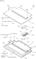
- FIG. 2 is an exploded perspective view of the loop heat pipe 100.
- FIGS. 3(a) and 3(b) illustrate a detailed configuration of a first side plate 111 and a second side plate 121.
- FIGS. 2 through 3(b) a detailed configuration of the loop heat pipe 100 in accordance with the present embodiment will be described.
- the loop heat pipe 100 in accordance with the present embodiment has a generally planar shape.
- the loop heat pipe 100 includes generally planar first and second side plates 111, 121, and generally planar wick 130 and bonding member 150 disposed between the first and second side plates 111, 121.
- the loop heat pipe 100 is configured with the first and second side plates 111, 121 and the wick 130 and the bonding member 150 sandwiched therebetween.
- the first side plate 111 includes first outer and inner surfaces 113, 115 of a generally rectangular shape in front view.
- the first side plate 111 further includes a first through-hole 1129 formed through opposite plate surfaces.
- the second side plate 121 includes second inner and outer surfaces 123, 125 of a generally rectangular shape in front view.
- the second side plate 121 further includes a second through-hole 1229 formed through opposite plate surfaces.
- the first and second side plates 111, 121 are made of a metal material such as copper.
- the wick 130 and the bonding member 150 are disposed between the first inner surface 115 of the first side plate 111 and the second inner surface 123 of the second side plate 121.
- the loop heat pipe 100 can diffuse heat using the first and second side plates 111, 121, i.e., its enclosure.
- the loop heat pipe 100 is of a generally planar shape with a thickness of, for example, less than or equal to 1 mm.
- the loop heat pipe 100 is also dimensioned to allow it to be installed in a smartphone, for example.
- the loop heat pipe 100 as a whole is dimensioned with a length of less than or equal to 100 mm, a width of less than or equal to 60 mm, and a thickness of less than or equal to 0.3 mm, for example.
- the loop heat pipe 100 is dimensioned with a thickness of less than or equal to 3%, more preferably less than or equal to 1%, of its planar dimension (e.g., length or width).
- the thickness direction of the loop heat pipe 100 i.e., the vertical direction in FIG. 2
- the thickness direction of the loop heat pipe 100 may be hereinafter referred to simply as the thickness direction.
- the lower side in the vertical direction in FIG. 2 may be referred to as the first face side, and the upper side in FIG. 2 may be referred to as the second face side.
- the direction in which the working fluid is transported in the wick 130 i.e., the direction extending between the upper left and the lower right in FIG. 2 , may be referred to simply as the transport direction.
- the upper left side in FIG. 2 may be referred to as the upstream side, and the lower right side may be referred to as the downstream side.
- the direction perpendicular to the vertical and transport directions in FIG. 2 may be referred to as the width direction.
- the left frontward side in the width direction in the page of FIG. 2 may be referred to as one side, and the right rearward side in the width direction in the page of FIG. 2 may be referred to
- the first side plate 111 includes a first recess 110 formed on the first inner surface 115.
- the first recess 110 is an annular region formed around the periphery of the first through-hole 1129 in the first inner surface 115.
- the first recess 110 includes a first evaporator region 112, a first vapor line region 116, a first condenser region 117, a first liquid line region 118, and a first opening region 119, which are annularly continuous with each other.
- the second side plate 121 includes a second recess 120 formed on the second inner surface 123.
- the second recess 120 is an annular region formed around the periphery of the second through-hole 1229 in the second inner surface 123.
- the second recess 120 has a mirrored shape to the first recess 110.
- the first and second recesses 110, 120 are in a mirror symmetry relationship.
- the second recess 120 includes a second evaporator region 122, a second vapor line region 126, a second condenser region 127, a second liquid line region 128, and a second opening region 129, which are annularly continuous with each other.
- the first and second recesses 110, 120 confront each other.
- the first and second evaporator regions 112, 122 form the evaporator 101.
- the first and second vapor line regions 116, 126 form the vapor line 105.
- the first and second condenser regions 117, 127 form the condenser 107.
- the first and second liquid line regions 118, 128 form the liquid line 109.
- the first and second opening regions 119, 129 form an opening that allows for injection of the working fluid into the first and second recesses 110, 120 from outside after bonding the first inner surface 115 of the first side plate 111 and the second inner surface 123 of the second side plate 121. To further illustrate, the opening formed by the first and second opening regions 119, 129 is closed after the injection of the working fluid.
- the first and second evaporator regions 112, 122, which form the evaporator 101, will now be described.
- the first evaporator region 112 is of a generally rectangular shape in plan view.
- the first evaporator region 112 includes a first wide region 1121 defining a space continuous with the first liquid line region 118, and a first narrow region 1123 defining a space downstream of the first wide region 1121 and continuous with the first vapor line region 116.
- the first wide region 1121 and the first narrow region 1123 are arranged in line with each other in the transport direction.
- the first wide region 1121 is dimensioned larger than the first narrow region 1123 in the width direction.
- the second evaporator region 122 is of a generally rectangular shape in plan view.
- the second evaporator region 122 includes a second wide region 1221 defining a space continuous with the second liquid line region 128, and a second narrow region 1223 defining a space downstream of the second wide region 1221 and continuous with the second vapor line region 126.
- the second wide region 1221 and the second narrow region 1223 are arranged in line with each other in the transport direction.
- the second wide region 1221 is dimensioned larger than the second narrow region 1223 in the width direction.
- the wick 130 is disposed inside the first and second evaporator regions 112, 122.
- a space that is closer to the liquid line 109 than the wick 130 is serves as a liquid reservoir 160, in which the liquid-phase working fluid is contained.
- the first and second wide regions 1121, 1221 define the liquid reservoir 160.
- a space that is closer to the vapor line 105 than the wick 130 is serves as a vapor space 140, through which the gas-phase working fluid passes.
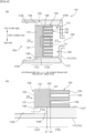
- FIGS. 4(a) and 4(b) illustrate a configuration around the wick 130.
- the wick 130 is made of a porous body, such as a porous metal of copper or the like.
- the wick 130 generates capillary forces in the working fluid, causing the working fluid to move.
- the effective pore size of the wick 130 is 0.1 to 50 ⁇ m.
- the porosity of the wick 130 is 25 to 80%. Any method may be used to measure the effective pore size and porosity. For example, the effective pore size and porosity may be measured based on apparent density measurement by water immersion, pore size distribution measurement by mercury porosimetry, or pore observation by X-ray CT.
- the wick 130 is dimensioned with, for example, a length of 10 mm to 300 mm in the width direction, a length of 3 mm to 100 mm in the transport direction, and a thickness of 0.01 mm to 1 mm, more preferably 0.1 mm to 0.5 mm.
- the wick 130 is dimensioned such that its thickness is, for example, about 0.01 to 1%, more preferably 0.1 to 0.5%, of the length in the width direction, i.e., its longitudinal length.
- the heating element 10 (see FIG. 1 ) is, for example, 10 mm wide and 10 mm long.
- the wick 130 is dimensioned with a larger width and length than the heating element 10.
- the wick 130 includes a generally rectangular wick base portion 131 having a longitudinal direction extending along the width direction, and wick prongs 133 projecting downstream in the transport direction from the wick base portion 131.
- a plurality of wick prongs 133 are provided at predetermined intervals in the width direction.
- the wick 130 includes a plurality of slits 135 located downstream in the transport direction and extending along the transport direction. The upstream end in the transport direction of the slit 135 is referred to as a slit bottom 136.
- the wick prong 133 is 0.5 mm to 2.0 mm long in the width direction and 10 mm to 20 mm long in the transport direction.
- the slit 135 is 0.5 mm to 2.0 mm long in the width direction, for example. To further illustrate, the slit 135 is longer in the width direction (wider) than the wick prong 133. The slit 135 may have the same length as or a different length than the wick prong 133 in the width direction. Besides the illustrated example, the distal end of the wick prong 133 and the slit bottom 136 may be rounded (curved).
- the wick 130 is generally comb-shaped (rake-shaped).
- the slits 135 formed in the wick 130 serve as vapor grooves, or so-called grooves, that facilitate the flow of the working fluid vaporized in the wick 130 toward the vapor line 105.
- the wick prongs 133 and the slits 135 are alternately arranged in the same plane, which allows the wick 130, the first side plate 111, and the second side plate 121 to be thinner while maintaining the mechanical strength.
- providing the wick prongs 133 and the slits 135 in the same plane improves the flexibility in disposing the heating element 10 ( FIG. 1 ), which is the heat source.
- the heating element 10 may be provided on either or both of the first outer surface 113 of the first side plate 111 and the second outer surface 125 of the second side plate 121.
- the wick 130 is disposed over both of a portion of the first wide region 1121 and a portion of the first narrow region 1123 of the first side plate 111 in the transport direction. To further illustrate, the wick 130 is disposed to develop (project) from the first narrow region 1123 toward the first wide region 1121.
- the wick 130 is sandwiched between a narrow first and second side faces 1127, 1128 in the first narrow region 1123.
- a wick first side face 138 which is a side face of the wick 130 along the transport direction, is bonded to the narrow first side face 1127 of the first side plate 111.
- a wick second side face 139 is bonded to the narrow second side face 1128 of the first side plate 111. Even if the material of the wick 130 shrinks during the formation of the wick 130 by sintering as described below, the wick 130 is prevented from being spaced from the narrow first and second side faces 1127, 1128.
- a wick upstream end face 137 is located within the first wide region 1121. Accordingly, the wick first and second side faces 138, 139 are exposed in the first wide region 1121. To further illustrate, the wick first and second side faces 138, 139 are spaced from wide first and second side faces 1124, 1125, respectively, of the first side plate 111. This permits the liquid-phase working fluid to flow into the wick 130 through the wick first and second side faces 138, 139 (see arrow C5 in FIG. 4(b) ). This increases the area where the wick 130 is in contact with the liquid-phase working fluid, improving the wetting of the wick 130.
- the wick 130 is disposed sandwiched between the first and second side plates 111, 121 as described above.
- the wick 130 also provides a partition between the vapor space 140 and the liquid reservoir 160.
- the liquid-phase working fluid may flow (leak) into the vapor space 140 or the gas-phase working fluid may flow into the liquid reservoir 160. Such inflow would reduce the heat exchange rate of the loop heat pipe 100.
- the wick 130 is formed on the first side plate 111 by applying a material for use as the wick 130 to the first inner surface 115 of the first side plate 111 (described below). This prevents a gap from being created between the wick 130 and the first inner surface 115 of the first side plate 111. Additionally, in the present embodiment, a bonding member 150 is disposed over the wick 130. This prevents a gap from being created between the wick 130 and the second inner surface 123 of the second side plate 121.
- the bonding member 150 includes a generally rectangular bonding member base portion 151 having a longitudinal direction extending along the width direction, and a bonding member narrow portion 153 projecting downstream in the transport direction from the bonding member base portion 151.
- the bonding member narrow portion 153 is of a generally rectangular shape having a longitudinal direction extending along the width direction, and is dimensioned narrower than the bonding member base portion 151 in the width direction.
- the bonding member 150 is a plate-shaped metal member made of bronze or the like.
- the bonding member 150 is located to cover the wick base portion 131 of the wick 130. To further illustrate, the bonding member 150 is disposed over both a portion of the first wide region 1121 and a portion of the first narrow region 1123 in the transport direction. The bonding member 150 is formed sandwiched between the narrow first and second side faces 1127, 1128 in the width direction. The bonding member 150 is also formed sandwiched between the wide first and second side faces 1124, 1125 in the width direction. A bonding member upstream end face 155 as shown is aligned with the wick upstream end face 137 in the transport direction. Note that the bonding member 150 is not limited to being configured as shown in the figures, provided that both ends thereof are in contact with the narrow first and second side faces 1127, 1128.
- the bonding member 150 need not be in contact with the wide first and second side faces 1124, 1125 in the width direction. Also, the bonding member 150 need not be disposed over both a portion of the first wide region 1121 and a portion of the first narrow region 1123 in the transport direction.
- the bonding member upstream end face 155 as shown need not be aligned with the wick upstream end face 137 in the transport direction.
- a bonding member downstream end face 157 which is a downstream end face of the bonding member 150 in the transport direction.
- the position of the bonding member downstream end face 157 in the transport direction is located between a virtual line L1, which extends along a step surface 1126 connecting the wide first side face 1124 and the narrow first side face 1127, and a virtual line L2, which extends along the slit bottoms 136. If the bonding member downstream end face 157 is located upstream of the virtual line L1 in the transport direction, leakage of the working fluid may occur. If the bonding member downstream end face 157 is located downstream of the virtual line L2 in the transport direction, the function of the slits 135 may degrade.
- the liquid-phase working fluid contained in the liquid reservoir 160 flows toward the wick 130 (see arrow C3) and permeates the wick 130.
- the liquid-phase working fluid is then heated and vaporized by the heat of the heating element 10 as it moves through the wick 130 due to capillary forces of the wick 130.
- the vaporized working fluid passes through the slits 135 and other portions toward the vapor line 105 (see arrow C1) and then flows through and exits the vapor line 105 for delivery to the condenser 107 (see FIG. 1 ).
- the liquefied working fluid in the condenser 107 then flows into the evaporator 101 and goes through the liquid reservoir 160 to permeate the wick 130 again.
- the above cycle is repeated without interruption of the flow of the working fluid at the wick 130.
- the heat generated in the heating element 10 is thus transported from the evaporator 101 to the condenser 107 (see FIG. 1 ).
- the first and second side plates 111, 121 are formed of a planar member made of copper or other metal material, which is processed to form the first and second recesses 110, 120.
- a 0.15 mm-thick copper flat plate is etched to form the first and second recesses 110, 120.
- the first and second recesses 110, 120 are 0.1 mm in depth.
- the regions in the first and second side plates 111, 121 where the first and second recesses 110, 120 are formed are 0.05 mm thick.
- etching is used to remove at least 50% of the thickness of the first and second side plates 111, 121.
- a through etching, or outer copper plate etching, is performed around the outer shape of the first and second side plates 111, 121 to allow the first and second side plates 111, 121 to be taken out.
- a through etching is also performed to form the first through-hole 1129 in the first side plate 111 and the second through-hole 1229 in the second side plate 121.
- the wick 130 and the bonding member 150 are formed on the first side plate 111 and the second side plate 121, respectively. After overlapping the first side plate 111 having the wick 130 formed thereon and the second side plate 121 having the bonding member 150 formed thereon, the wick 130 and the bonding member 150 are secured to each other.
- the wick 130 as shown is formed on the first side plate 111 by applying a material of the wick 130 to the first side plate 111.
- the wick 130 is formed by applying a metal paste containing pure copper powder to predetermined regions in the first wide region 1121 and the first narrow region 1123 of the first side plate 111.
- a mask 180 (see FIG. 5 below) is used to apply the wick 130, as described in detail below.
- the bonding member 150 as shown is formed on the second side plate 121 by applying a material of the bonding member 150 to the second side plate 121.
- the bonding member 150 is formed by applying a metal paste containing bronze powder to predetermined regions in the second wide region 1221 and the second narrow region 1223 of the second side plate 121.
- the bonding member 150 is applied using any well-known masking technique, such as covering the periphery of the regions where the bonding member 150 is formed with so-called masking tape 280 (see FIG. 6 (c-2) below).
- the bonding member 150 is 4 mm long in the transport direction.
- the bonding member base portion 151 is 3 mm long in the transport direction
- the bonding member narrow portion 153 is 1 mm long in the transport direction.
- FIG. 5 illustrates a schematic configuration of the mask 180.
- the mask 180 is a 0.3 mm-thick planar metal member.
- the mask 180 includes a wick-shaped opening 190 as a through-hole.
- the wick-shaped opening 190 includes a wick base portion region 191 defining the region where the wick base portion 131 is formed and a wick prong region 193 defining the region where the wick prongs 133 are formed.
- the wick base portion region 191 is a generally rectangular portion having a longitudinal direction extending along the width direction.
- the wick prong region 193 is a portion projecting downstream in the transport direction from the wick base portion region 191.
- the mask 180 is positioned in alignment with the first side plate 111 having the first recess 110 formed therein. Then, the metal paste containing pure copper powder is introduced from above the mask 180 into the wick-shaped opening 190 and applied by, for example, scraping off excess metal paste with a rubber blade (so-called squeegee) or the like. This results in the material of the wick 130 being disposed in the first recess 110 at a predetermined thickness (e.g., 0.3 mm). This applied material of the wick 130 is solidified by sintering or other means to form the wick 130 in the first recess 110.
- the use of the mask 180 can, for example, simplify the process of forming the wick 130 having the wick prongs 133.
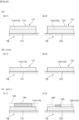
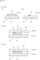
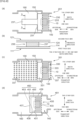
- FIGS. 6(a) through 7(f) illustrate processes of manufacturing the loop heat pipe 100.
- the first side plate 111 has already been masked except for the regions where the first recess 110 is to be formed, and where the above through etching is to be performed (i.e., the periphery around its outer profile, as well as the first through-hole 1129).
- the second side plate 121 has already been masked except for the regions where the second recess 120 is to be formed, and where the above through etching is to be performed (i.e., the periphery around its outer profile, as well as the second through-hole 1229).
- the first and second side plates 111, 121 are each placed on a table TB. Then, as shown in FIG. 6(b) , the first and second side plates 111, 121 are etched to form the first and second recesses 110, 120. Then, as shown in FIG. 6(c) , metal paste is applied to the first and second recesses 110, 120. Specifically, as shown in FIG. 6 (c-1), the mask 180 is placed on a first bottom face 114 of the first recess 110, and a first metal paste 149 for use as the wick 130 is applied. As shown in FIG. 6 (c-2), masking tape 280 is placed on a second bottom face 124 of the second recess 120, and a second metal paste 159 for use as the bonding member 150 is applied.
- the first and second metal pastes 149, 159 are heated under their respective conditions (with details to follow).
- the first metal paste 149 is sintered, resulting in the wick 130.
- This formed wick 130 is secured to the first bottom face 114.
- the second metal paste 159 is sintered, resulting in the bonding member 150. This formed bonding member 150 is secured to the second bottom face 124.
- solder is placed around the first and second recesses 110, 120 of the first and second side plates 111, 121.
- solder is placed on the raised portions of the first and second side plates 111, 121.
- the amount of solder placed on the raised portions is defined such that the solder, when molten, does not flow into the first and second recesses 110, 120.
- the position of solder placed on the raised portions is defined such that the solder, when molten, does not flow into the first and second recesses 110, 120.
- the first and second side plates 111, 121 with the solder placed thereon are stacked. This results in the wick 130 and the bonding member 150 confronting and abutting each other.
- the first and second side plates 111, 121 may then be pressed (see arrow F1 in the figure) to adjust (reduce) the thickness of the wick 130.
- the wick 130 and the bonding member 150 are bonded by heating the first and second side plates 111, 121. Then, after leaving the furnace, treatment is applied to enhance sealing.
- treatment is applied to enhance sealing.
- any well-known technique may be employed to further ensure sealing, such as placing solder on side faces (e.g., 0.3 mm thick) of the first and second side plates 111, 121, or applying and curing a sealant such as silicone- or UV-curing resin.
- the first and second side plates 111, 121 are supported on the flat table TB when they are heated to sinter the first and second metal pastes 149, 159. This may reduce deformation of the first and second side plates 111, 121 due to heating, compared to when the first and second side plates 111, 121 are not supported on the table TB.
- the first and second metal pastes 149, 159 may be prepared as follows.
- the first metal paste 149 for use as the wick 130 can be prepared by mixing pure copper powder with a grain size of 45 ⁇ m or less into a binder solution.
- the second metal paste 159 for use as the bonding member 150 can be prepared by mixing tin-50 wt.% bronze powder with a grain size of 45 ⁇ m or less into a binder solution.
- the binder solution consists of a binder component and an organic solvent.
- the binder component can be selected from, but is not limited to, acrylic, butyral, and cellulose-based components.
- the organic solvent can be selected from, but is not limited to, acetone, benzene, isopropanol, methanol, ethanol, toluene, n-butanol, xylene, ethylene glycol, ethyl acetate, terpineol, butyl acetate, tetrahydrofuran (THF), carbon tetrachloride, methyl ethyl ketone (MEK), chloroform, methyl isobutyl ketone (MIBK), n-hexane, methanol, and cyclohexane.
- the first and second metal pastes 149, 159 are debinded and sintered in a mesh belt sintering furnace.
- the first and second metal pastes 149, 159 placed (applied) on the first and second side plates 111, 121 are sintered under the following conditions, for example.
- the debinding temperature may be 600°C
- the sintering temperature may be 920°C
- the hold time may be 30 minutes
- the atmosphere gas may be 80% nitrogen and 20% hydrogen.
- the debinding temperature may be 600°C
- the sintering temperature may be 600°C
- the hold time may be 30 minutes
- the atmosphere gas may be 80% nitrogen and 20% hydrogen.
- the first and second side plates 111, 121 are secured, for example, under the following conditions. First, flux that activates solder is applied to the first side plate 111, and then solder (e.g., lead solder containing 60% tin and 40% lead) is placed on top of it, followed by applying flux onto the solder. Then, with the first and second side plates 111, 121 overlapped, the portions where the wick 130 and the bonding member 150 are formed are pressed from outside (see arrow F1 in the figure) to adjust the combined thickness of the wick 130 and the bonding member 150 to equal the channel height.
- solder e.g., lead solder containing 60% tin and 40% lead
- the first and second side plates 111, 121 are secured (temporarily fastened) by spot welding or other means. Then, solder bonding and bonding of the wick 130 and the bonding member 150 are carried out in a mesh belt sintering furnace. This bonding is carried out, for example, under the following heat treatment conditions. That is, the temperature may be 660°C, the hold time may be 30 minutes, and the atmosphere gas may be 80% nitrogen and 20% hydrogen. Additionally, the first and second side plates 111, 121 are sandwiched between ceramic plates, and the heat treatment is applied with a weight load of 1 kg.
- the loop heat pipe 100 formed under the above conditions was leak tested, which showed that there were no problems with degassing.
- heat load testing on the produced loop heat pipe 100 proved that it could operate at 4.5W to 10W.
- the wick 130 and the second side plate 121 are secured to each other via the bonding member 150. This securing with the bonding member 150 will be described.
- the wick 130 formed by sintering the first metal paste 149 is bonded at its first face side in the thickness direction to the first side plate 111. Additionally, the wick 130 is required to be bonded (sealed) at its second face side in the thickness direction to the second side plate 121. If, unlike the present embodiment, solder (e.g., 500°C) is used instead of the bonding member 150 to bond the wick 130 to the second side plate 121, the solder would be absorbed by the wick 130, with the consequent risk of degrading the function of the wick 130.
- solder e.g., 500°C
- brazing e.g., 800°C
- diffusion bonding e.g., 1000°C
- the bonding member 150 is used for bonding.
- the bonding member 150 is made of a material (e.g., bronze) that has a lower melting point than that of the wick 130 (e.g., pure copper).
- the bonding member 150 may be made of any material that is easily alloyed with or compatible with the wick 130 and the second side plate 121.
- the wick 130 is made of pure copper, brass or other material may be used as the bonding member 150.
- the material of the bonding member 150 can be viewed as one that has the same composition (e.g., copper) as the wick 130 and the second side plate 121.
- the material of the bonding member 150 can also be viewed as one that has a lower melting point than the alloy of the second side plate 121.
- the sintering of the first metal paste 149, or the first heating is carried out at 920°C.
- the bonding of the wick 130 to the bonding member 150, or the second heating, is carried out at 660°C, which is lower than the first heating temperature. This reduces possible changes in structure of the wick 130 due to the second heating.
- the bonding of the wick 130 to the bonding member 150 allows the wick 130 to be secured to both the first and second side plates 111, 121.
- the secured wick 130 and bonding member 150 serve as a pressure bulkhead between the vapor space 140 and the liquid reservoir 160.
- FIGS. 8(a) through 8(d) illustrate a first variation.
- FIGS. 8(a) through 8(d) a first variation will be described.
- the same reference numerals are used to refer to the same features as those in the above embodiment, and their detailed description may be omitted.
- the wick 130 has been described as having a generally comb-like shape. However, this is not limiting, and the wick 130 may have any other structure that allows it to be installed in the same plane.
- a wick 230 may be formed as shown in FIG. 8(a) .
- the wick 230 includes a wick base portion 231 having a longitudinal direction extending along the width direction, a plurality of wick prongs 233 projecting downstream in the transport direction from the wick base portion 231, and a wick protrusion 237 projecting upstream in the transport direction from the wick base portion 231.
- the wick 230 is formed by application of a material for use as the wick 230, as in the above embodiment.
- the working fluid when the liquid reservoir 160 contains a small amount of working fluid, the working fluid may be unevenly distributed in the liquid reservoir 160. Such uneven distribution of the working fluid may inhibit it from being supplied to the wick 230, with the consequent risk of degrading the operating performance of the wick 230.
- the wick protrusion 237 is formed protruding into the interior of the liquid reservoir 160. This may ensure a stable supply of the working fluid to the wick base portion 231 and the wick prongs 233 through the wick protrusion 237, even when the working fluid is unevenly distributed within the liquid reservoir 160.
- the wick protrusion 237 can be viewed as another wick, or a secondary wick, for supplying the working fluid to the wick base portion 231 and other portions.
- the wick protrusion 237 may be of any material, shape (e.g., pillar or mesh form), etc. that can provide a structure having predetermined capillary forces.
- the wick protrusion 237 may be dimensioned such that flow pressure loss is not greater than a predetermined value.
- the wick protrusion 237 is bonded at both ends in the thickness direction to the first bottom face 114 of the first side plate 111 and the second bottom face 124 of the second side plate 121. This may reduce or prevent deformation of the first and second side plates 111, 121. To further illustrate, the presence of the wick protrusion 237 may reduce or prevent bulging or sinking (denting) of the first and second side plates 111, 121 even when, for example, the first and second side plates 111, 121 are configured with a small thickness.
- a wick 330 may be configured as shown in FIG. 8(c) .
- the wick 330 includes a wick base portion 331 having a longitudinal direction extending along the width direction, a plurality of wick prongs 333 projecting downstream in the transport direction from the wick base portion 331, and a plurality of wick remote portions 337 spaced from the wick base portion 331 and the wick prongs 333.
- the wick 330 is formed by application of a material for use as the wick 330, as in the above embodiment. Note that some or all of the wick remote portions 337 can be formed in the etching process of forming the first and second recesses 110, 120 as described above.
- wick remote portions 337 are formed in the liquid reservoir 160.
- Each wick remote portion 337 is bonded at both ends in the thickness direction to the first bottom face 114 of the first side plate 111 and the second bottom face 124 of the second side plate 121, which may reduce or prevent deformation of the first and second side plates 111, 121.
- the wick remote portions 337 are not limited to being located in the liquid reservoir 160 as in the illustrated example, and may be provided in the vapor space 140 in addition to or instead of in the liquid reservoir 160.
- the wick remote portion 337 may also be provided in the vapor line 105, the condenser 107, and/or the liquid line 109, etc.
- the wick remote portions 337 function to prevent channel blockage or constriction due to negative pressure.
- the wick remote portions 337 are dimensioned and mutually spaced so as not to obstruct the flow of the working fluid. Additionally, the manufacturing process may be simplified by forming the wick remote portions 337 using the same material and process as used for forming the wick base portion 331 and the wick prongs 333. Note that the wick base portion 331 and the wick prongs 333 may be made of different materials.
- a wick 430 may be disposed in the liquid reservoir 160.
- This wick 430 includes a wick base portion 431 having a longitudinal direction extending along the width direction, and a plurality of wick prongs 433 projecting downstream in the transport direction from the wick base portion 431.
- the wick base portion 431 and the wick prongs 433 are disposed in the liquid reservoir 160.
- the wick 430 can receive a stable supply of the working fluid even when the working fluid is unevenly distributed within the liquid reservoir 160.
- a bonding member 450 is placed over the wick 430.
- the bonding member 450 is generally U-shaped.
- the bonding member 450 includes an upstream portion 451 extending along the wick upstream end face 437, a first portion 453 extending along the wick first side face 438, and a second portion 455 extending along the wick second side face 439.
- the upstream portion 451, the first portion 453, and the second portion 455 reduce or prevent leakage of the working fluid in the region of the wick 430 in contact with the liquid reservoir 160.
- FIGS. 9(a) through 9(e) illustrate a second variation.
- the wick 130 has been described as being generally comb-shaped. However, this is not limiting.
- a wick 1130 may be formed as shown in FIG. 9(a) .
- the wick 1130 includes a wick base portion 1131 having a longitudinal direction extending along the width direction, and a plurality of wick prongs 1133 projecting downstream in the transport direction from the wick base portion 1131.
- Each of the wick prongs 1133 has a width direction length that varies at different positions in the transport direction.
- the wick prongs 1133 are dimensioned to be smaller in the width direction as one moves downstream in the transport direction.
- slits 1135 which define gaps between the respective wick prongs 1133, are dimensioned to be larger in the width dimension as one moves downstream in the transport direction.
- a wick 1230 may be formed as shown in FIG. 9(b) .
- the wick 1230 includes a wick base portion 1231 having a longitudinal direction extending along the width direction, and a plurality of wick prongs 1233 projecting downstream in the transport direction from the wick base portion 1231.
- the wick prongs 1233 are curved in a generally S-shape fashion, or in other words, they are of a corrugated shape. Slits 1235 are also curved accordingly.
- a wick 1330 may be formed as shown in FIG. 9(c) .
- the wick 1330 is configured to be spaced in the transport direction and connected at the center in the width direction.
- the wick 1330 includes a plurality of wick base portions 1331, 1333, 1335 each having a longitudinal direction extending along the width direction, and a connecting portion 1337 that connects the wick base portions 1331, 1333, 1335 at the center in the width direction. Gaps 1336, 1338 created between the wick base portions 1331, 1333, 1335 serve as channels for the working fluid.
- a wick 1430 may be formed as shown in FIG. 9(d) .
- the wick 1430 includes a wick base portion 1431 having a longitudinal direction extending along the width direction, and a plurality of wick prongs 1433 projecting downstream in the transport direction from the wick base portion 1431.
- Each of the wick prongs 1433 includes a wide portion 1437 projecting in the width direction from the center of the wick prong 1433 in the transport direction. Gaps 1435 between the respective wick prongs 1433 serve as channels for the working fluid.
- a wick 1530 may be formed as shown in FIG. 9(e) .
- the wick 1530 includes a wick base portion 1531 having a longitudinal direction extending along the width direction, two wick prongs 1533 projecting downstream in the transport direction from both ends in the width direction of the wick base portion 1531, and protrusions 1535 projecting downstream in the transport direction from the wick base portion 1531.
- Each of the protrusions 1535 includes a wide portion 1537 that is located downstream in the transport direction and dimensioned larger in the width direction. In the illustrated example, the wide portion 1537 is generally circular in plan view. Gaps 1536 between the respective wick prongs 1533 and protrusions 1535 serve as channels for the working fluid.
- FIGS. 10(a) through 10(e) illustrate a third variation.
- the wick 130 has been described as being formed by applying it.
- the shape of the wick 130 can be easily altered by, for example, varying the thickness of mask 180.
- the configuration of the wick 130 can be altered by changing the manner of application of the wick 130 through, for example, varying the shape of the mask 180. This facilitates the design of the wick 130 at the design stage according to the performance required of the wick 130.
- a mask 2180 may be configured to have a thickness that varies at different positions in the transport direction.
- the mask 2180 is configured such that a region 2181 where a wick-shaped opening 2190 is formed decreases in thickness as one moves downstream in the transport direction.
- the use of the mask 2180 results in the formation of a wick 2130 as shown in FIG. 10(b) .
- the wick 2130 has a thickness dimension that varies at different positions in the transport direction. Specifically, the wick 2130 is configured to decrease in thickness as one moves downstream in the transport direction.
- a wick 2230 may be formed as shown in FIG. 10(c) .
- the material composition of the wick 2230 varies at different positions in the transport direction.
- the wick 2230 is configured to have a smaller average aperture size as one moves downstream in the transport direction.
- the wick 2230 includes a first portion 2231 with a first average aperture size and a second portion 2233 with a second average aperture size that is different from (smaller than) the first average aperture size.
- the wick 2230 has a constant thickness dimension, but is configured such that the first portion 2231 decreases in thickness as one moves downstream in the transport direction, and the second portion 2233 increases in thickness as one moves downstream in the transport direction.
- Mutually different materials e.g., with different grain sizes, may be used for the first and second portions 2231, 2233.
- the material for use as the second portion 2233 is applied over the first portion 2231, and then the materials are sintered to form the wick 2230.
- a wick 2330 may be formed as shown in FIG. 10(d) .
- the wick 2330 has a structure that varies at different positions in the transport direction. Specifically, the wick 2330 is configured such that its downstream portion in the transport direction has a smaller average aperture size than its upstream portion in the transport direction.
- the average aperture size of the wick 2330 is reduced by pressing a part of the applied material, without using multiple materials. Specifically, after applying a material 2332 for use as the wick 2330 at a certain thickness, only the downstream portion 2333 in the transport direction is pressed (see arrow F3). This results in the downstream portion 2333 in the transport direction having a smaller average aperture size than the upstream portion 2331 in the transport direction. This also results in the downstream portion 2333 in the transport direction having a smaller thickness than the upstream portion 2331 in the transport direction.
- a wick 2430 may be formed as shown in FIG. 10(e) .
- a material 2431 for use as the wick 2430 is applied at an inclination such that it becomes thicker (higher) toward the downstream end in the transport direction, and then pressed to level the thickness (see arrow F4).
- the average aperture size decreases (slopes) as one moves downstream in the transport direction.
- the upstream and downstream portions 2435, 2437 in the transport direction have the identical thickness.
- FIGS. 11(a) and 11(b) illustrate devices with the loop heat pipe 100.
- the loop heat pipe 100 is provided in an electronic device such as a mobile phone 800.
- the depicted mobile phone 800 is a so-called smartphone.
- the mobile phone 800 includes a central processing unit (CPU) 801, which is an example of the heating element, and the loop heat pipe 100 to cool the CPU 801.
- the heat generated by the CPU 801 is controlled by the loop heat pipe 100.
- the loop heat pipe 100 does not require an external power supply, as described above. In other words, it can operate without power.
- the loop heat pipe 100 may enable a long-distance heat transport (e.g., 100 mm to 1 m) and a highly efficient heat transport using latent heat.
- the loop heat pipe 100 is thin, offering layout flexibility.
- the loop heat pipe 100 described above is a device that may meet these performance requirements.
- the above loop heat pipe 100 may be provided in personal computers, tablet terminals, projectors, etc.
- the loop heat pipe 100 may also be provided in various devices such as electronic control units (ECUs) and batteries installed in automobiles etc., or satellites.
- ECUs electronice control units
- the loop heat pipe 100 may be installed in a card 900.
- the card 900 is a so-called smart card, whose specifications are defined by an international standard (ISO/IEC7810).
- Smart cards are generally classified into contact and contactless types. Inside the card are 0.4-mm or less thick devices, such as IC chips, near field communication (NFC) antennas, Bluetooth ® communication, fingerprint sensors, displays, power supply ICs, DC/DC converters, batteries and capacitors, which are incorporated as needed. In the future, along with the increased performance of IC chips and various devices, smart cards are expected to be used like a PC.
- the driving power for the PC is received through a card reader 950 in the case of a contact type, and through the NFC antenna in the case of a contactless type. As a CPU 901 for the PC generates more heat with an increase in computing speed, a cooling mechanism needs to be provided within the card 900.
- the loop heat pipe 100 which is 0.3 mm thick for example, can be incorporated into the card 900.
- the loop heat pipe 100 may be configured to reject heat by exposing some of the surfaces of the condenser 107 (e.g., the condensation surface) to the outside of the card 900.
- the loop heat pipe 100 can be an effective solution to design problems where the card 900 is a contact type and the CPU 901 for the PC has to be located in a region of the card 900 that will be inside the card reader 950.
- FIG. 12 illustrates a variation of the loop heat pipe 1100.
- a loop heat pipe 1100 may include a fin structure 1101 that increases the heat transfer area, and may be configured to dissipate heat through the fin structure 1101.
- the mask 180 is used to apply the wick 130.
- this is not limiting.
- any well-known technique such as a screen used for screen printing, a dispenser, or the masking tape 280, may be used to apply the wick 130 to a predetermined region.
- the wick 130 may be formed by forming a sheet (thin plate) of the wick material using a coater and then cutting it into a predetermined shape.
- the wick 130 has been described as being formed by applying it, this is not limiting as to how the wick 130 is formed.
- the wick 130 may be formed by placing a powdered material of the wick 130 on the first side plate 111 and sintering it.
- the powdered material may be spread at a thickness of about 0.1 mm on the first side plate 111 at locations where the wick 130 is to be formed.
- combining the powdered material and a binder into a paste may enable a thin and uniform application of the material of the wick 130.
- the material used as the wick 130 is not limited to the porous metal material described above.
- the wick 130 may be made of any other material, such as a porous ceramic material, porous glass material, or porous fiber, etc., that can be processed into powder and can secure the positions of the components relative to each other when heated.
- first and second recesses 110, 120 have been described as being formed by etching, this is not limiting.
- the first and second recesses 110, 120 may be formed by cutting, pressing, or performing any other well-known process on the first and second side plates 111,121.
- only one of the first and second recesses 110, 120 may be formed, provided that a space for placement of the wick 130 and the bonding member 150 can be provided between the first and second side plates 111, 121.
- forming the first recess 110 by etching as described above can roughen the first bottom face 114, which may ensure a more reliable securing of the wick 130 to the first side plate 111.
- forming the second recess 120 by etching can roughen the second bottom face 124, which may ensure a more reliable securing of the bonding member 150 to the second side plate 121.
- the first and second side plates 111, 121 are not limited to being generally plate-shaped, provided that are configured to have a reduced thickness dimension.
- the first and second side plates 111, 121 may have unevenness on their plate surface or may have an additional component(s) secured to their plate surface.
- the first and second side plates 111, 121 can be viewed as a body and a lid covering the body, respectively.
- the loop heat pipe 100 may be formed by sandwiching a frame, separate from the first and second side plates 111, 121, between the first and second side plates 111, 121.
- the bonding member 150 has been described as being formed by applying the material of the bonding member 150 and then sintering it, this is not limiting.
- the bonding member 150 may be pre-formed as a plate-shaped member, and the plate-shaped bonding member 150 may be secured to the second side plate 121 and the wick 130 by being heated while being sandwiched between the second side plate 121 and wick 130.
- first and second side plates 111, 121 have been described as being bonded by soldering, this is not limiting.
- the first and second side plates 111, 121 may be bonded by brazing, provided that it is possible to prevent the flow of brazing material into the first and second recesses 110, 120.
- diffusion bonding may be used, provided that it is possible to prevent any channel blockage through the provision of a pillar(s) or other means.
- bonding may be performed by adhesive bonding, laser bonding, ultrasonic bonding, or friction stir bonding.
- loop heat pipe 100 has been described as an example of the heat exchanger, this is not limiting and any other two-phase heat transport device may be used.
- the above configuration of the wick 130, the first side plate 111, etc. may be employed in other heat exchangers such as vapor chambers.
- the loop heat pipe 100 is an example of the heat exchanger.
- the first side plate 111 is an example of the first plate member and the body.
- the first recess 110 is an example of the recess.
- the first metal paste 149 is an example of the powder-containing material and the first material.
- the wick 130 is an example of the evaporating body.
- the second side plate 121 is an example of the second plate member and the lid.
- the wick-shaped opening 190 is an example of the hole.
- the mask 180 is an example of the covering member.
- the wick base portion 1131 is an example of the base body.
- the wick prong 1133 is an example of the downstream body and the protrusion.
- the first portion 2231 is an example of the first material.
- the second portion 2233 is an example of the second material.
- the wick remote portion 337 is an example of the sintered body and another sintered body.
- the mobile phone 800 is an example of the device.
- the heating element 10 is an example of the heating component.
- the second metal paste 159 is an example of the second material.
- the bonding member 150 is an example of the sintered body and the bonding layer.
Landscapes
- Engineering & Computer Science (AREA)
- Physics & Mathematics (AREA)
- Thermal Sciences (AREA)
- Mechanical Engineering (AREA)
- General Engineering & Computer Science (AREA)
- Sustainable Development (AREA)
- Life Sciences & Earth Sciences (AREA)
- Microelectronics & Electronic Packaging (AREA)
- Manufacturing & Machinery (AREA)
- Cooling Or The Like Of Semiconductors Or Solid State Devices (AREA)
- Heat-Exchange Devices With Radiators And Conduit Assemblies (AREA)
- Application Of Or Painting With Fluid Materials (AREA)
- Chemical & Material Sciences (AREA)
- Materials Engineering (AREA)
Abstract
Description
- The present invention relates to a manufacturing method and a heat exchanger.
-
Patent Document 1 discloses a loop heat pipe including an evaporator, a condenser, a liquid return pipe, and a wick that is located inside the evaporator and generates capillary forces in order to efficiently cool heating elements regardless of an installation angle. - Patent Document 1:
Japanese Patent Application Laid-Open Publication No. 2008-215702 - Recent miniaturization and increased performance of devices, such as electronic devices, has led to an increased heat density of heating elements provided in the devices. In addition, a trend toward thinner-profile devices, for example, has been accompanied by the need for a heat exchanger that can remove heat flux from heating elements while having a reduced thickness dimension.
- It is an object of the present disclosure to provide a method for manufacturing a heat exchanger and the like with a reduced thickness dimension.
- According to certain embodiments of the present disclosure, there is provided a method for manufacturing a heat exchanger including an evaporating body configured to absorb heat from outside and evaporate a liquid-phase working fluid into a gas phase while moving the working fluid by capillary forces. The method includes steps of: forming a recess in a plate surface of a first plate member, the first plate member being plate-shaped; applying a powder-containing material to a predetermined region in the recess; solidifying the material applied to the predetermined region to form the evaporating body; and covering the recess having the evaporating body formed thereon with a second plate member, the second plate member being plate-shaped, and securing the first plate member to the second plate member.
- In accordance with the present disclosure, it is possible to manufacture a heat exchanger and the like with a reduced thickness dimension.
-
-
FIG. 1 illustrates a schematic configuration of a loop heat pipe in accordance with an exemplary embodiment. -
FIGS. 2 is an exploded perspective view of the loop heat pipe. -
FIGS. 3(a) and 3(b) illustrate a detailed configuration of a first side plate and a second side plate. -
FIGS. 4(a) and 4(b) illustrate a configuration around a wick. -
FIG. 5 illustrates a schematic configuration of a mask. -
FIGS. 6(a) through 6(c) illustrate processes of manufacturing the loop heat pipe. -
FIGS. 7(d) through 7(f) illustrate processes of manufacturing the loop heat pipe. -
FIGS. 8(a) through 8(d) illustrate a first variation. -
FIGS. 9(a) through 9(e) illustrate a second variation. -
FIGS. 10(a) through 10(e) illustrate a third variation. -
FIGS. 11(a) and 11(b) illustrate devices with the loop heat pipe. -
FIG. 12 illustrates a variation of the loop heat pipe. - Exemplary embodiments will now be described with reference to the drawings.
-
FIG. 1 illustrates a schematic configuration of aloop heat pipe 100 in accordance with an exemplary embodiment. - Referring initially to
FIG. 1 , a configuration of theloop heat pipe 100 in accordance with an exemplary embodiment will be described. Theloop heat pipe 100 of the present embodiment is a heat exchanger that is configured to circulate a working fluid therein to cool aheating element 10, such as a central processing unit (CPU) in an electronic device, without power supply from outside. - More specifically, the
loop heat pipe 100 includes anevaporator 101 configured to evaporate the working fluid to cool theheating element 10 using the latent heat of vaporization of the working fluid, and acondenser 107 configured to dissipate the heat of the working fluid vaporized in theevaporator 101 to liquefy it. - The
loop heat pipe 100 further includes avapor line 105 configured to deliver the working fluid vaporized in theevaporator 101 to thecondenser 107, and aliquid line 109 configured to deliver the working fluid liquefied in thecondenser 107 to theevaporator 101. Theloop heat pipe 100 is filled with the working fluid that changes between liquid and vapor phases. For example, the working fluid may be water, alcohol, ammonia, etc. - Referring to
FIG. 1 , the operation of theloop heat pipe 100 will now be described. - Heat generated in the
heating element 10 is transferred to the evaporator 101 (see arrows H1). The working fluid having absorbed the heat in theevaporator 101 is vaporized and delivered through the vapor line 105 (see arrow A1) to the condenser 107 (see arrow A2). The working fluid delivered to thecondenser 107 dissipates its heat (see arrows H2) and liquefies. The liquefied working fluid is then delivered through the liquid line 109 (see arrow A3) back to the evaporator 101 (see arrow A4). As such, theloop heat pipe 100 is a powerless fluid device and also a two-phase heat transport device driven by the capillary force of the fluid. -
FIG. 2 is an exploded perspective view of theloop heat pipe 100. -
FIGS. 3(a) and 3(b) illustrate a detailed configuration of afirst side plate 111 and asecond side plate 121. - Referring next to
FIGS. 2 through 3(b) , a detailed configuration of theloop heat pipe 100 in accordance with the present embodiment will be described. - As shown in
FIG. 2 , theloop heat pipe 100 in accordance with the present embodiment has a generally planar shape. Theloop heat pipe 100 includes generally planar first andsecond side plates planar wick 130 and bondingmember 150 disposed between the first andsecond side plates loop heat pipe 100 is configured with the first andsecond side plates wick 130 and thebonding member 150 sandwiched therebetween. - The
first side plate 111 includes first outer andinner surfaces first side plate 111 further includes a first through-hole 1129 formed through opposite plate surfaces. Thesecond side plate 121 includes second inner andouter surfaces second side plate 121 further includes a second through-hole 1229 formed through opposite plate surfaces. The first andsecond side plates wick 130 and thebonding member 150 are disposed between the firstinner surface 115 of thefirst side plate 111 and the secondinner surface 123 of thesecond side plate 121. - The
loop heat pipe 100 can diffuse heat using the first andsecond side plates loop heat pipe 100 is of a generally planar shape with a thickness of, for example, less than or equal to 1 mm. Theloop heat pipe 100 is also dimensioned to allow it to be installed in a smartphone, for example. Specifically, theloop heat pipe 100 as a whole is dimensioned with a length of less than or equal to 100 mm, a width of less than or equal to 60 mm, and a thickness of less than or equal to 0.3 mm, for example. To further illustrate, theloop heat pipe 100 is dimensioned with a thickness of less than or equal to 3%, more preferably less than or equal to 1%, of its planar dimension (e.g., length or width). - The thickness direction of the
loop heat pipe 100, i.e., the vertical direction inFIG. 2 , may be hereinafter referred to simply as the thickness direction. The lower side in the vertical direction inFIG. 2 may be referred to as the first face side, and the upper side inFIG. 2 may be referred to as the second face side. The direction in which the working fluid is transported in thewick 130, i.e., the direction extending between the upper left and the lower right inFIG. 2 , may be referred to simply as the transport direction. The upper left side inFIG. 2 may be referred to as the upstream side, and the lower right side may be referred to as the downstream side. The direction perpendicular to the vertical and transport directions inFIG. 2 may be referred to as the width direction. The left frontward side in the width direction in the page ofFIG. 2 may be referred to as one side, and the right rearward side in the width direction in the page ofFIG. 2 may be referred to as the other side. - As shown in
FIG. 3(a) , thefirst side plate 111 includes afirst recess 110 formed on the firstinner surface 115. Thefirst recess 110 is an annular region formed around the periphery of the first through-hole 1129 in the firstinner surface 115. To further illustrate, thefirst recess 110 includes a firstevaporator region 112, a firstvapor line region 116, afirst condenser region 117, a firstliquid line region 118, and afirst opening region 119, which are annularly continuous with each other. - As shown in
FIG. 3(b) , thesecond side plate 121 includes asecond recess 120 formed on the secondinner surface 123. Thesecond recess 120 is an annular region formed around the periphery of the second through-hole 1229 in the secondinner surface 123. Thesecond recess 120 has a mirrored shape to thefirst recess 110. In other words, the first andsecond recesses second recess 120 includes a secondevaporator region 122, a secondvapor line region 126, asecond condenser region 127, a secondliquid line region 128, and asecond opening region 129, which are annularly continuous with each other. - When the first
inner surface 115 of thefirst side plate 111 and the secondinner surface 123 of thesecond side plate 121 are positioned face-to-face, the first andsecond recesses evaporator regions evaporator 101. Likewise, the first and secondvapor line regions vapor line 105. The first andsecond condenser regions condenser 107. The first and secondliquid line regions liquid line 109. - The first and
second opening regions second recesses inner surface 115 of thefirst side plate 111 and the secondinner surface 123 of thesecond side plate 121. To further illustrate, the opening formed by the first andsecond opening regions - The first and second
evaporator regions evaporator 101, will now be described. - First, the first
evaporator region 112 is of a generally rectangular shape in plan view. The firstevaporator region 112 includes a firstwide region 1121 defining a space continuous with the firstliquid line region 118, and a firstnarrow region 1123 defining a space downstream of the firstwide region 1121 and continuous with the firstvapor line region 116. The firstwide region 1121 and the firstnarrow region 1123 are arranged in line with each other in the transport direction. The firstwide region 1121 is dimensioned larger than the firstnarrow region 1123 in the width direction. - Similarly, the second
evaporator region 122 is of a generally rectangular shape in plan view. The secondevaporator region 122 includes a secondwide region 1221 defining a space continuous with the secondliquid line region 128, and a secondnarrow region 1223 defining a space downstream of the secondwide region 1221 and continuous with the secondvapor line region 126. The secondwide region 1221 and the secondnarrow region 1223 are arranged in line with each other in the transport direction. The secondwide region 1221 is dimensioned larger than the secondnarrow region 1223 in the width direction. - As will be detailed below, the
wick 130 is disposed inside the first and secondevaporator regions evaporator regions liquid line 109 than thewick 130 is serves as aliquid reservoir 160, in which the liquid-phase working fluid is contained. In the illustrated example, the first and secondwide regions liquid reservoir 160. Also, in the interiors of the first and secondnarrow regions vapor line 105 than thewick 130 is serves as avapor space 140, through which the gas-phase working fluid passes. -
FIGS. 4(a) and 4(b) illustrate a configuration around thewick 130. - Referring next to
FIGS. 4(a) and 4(b) , a configuration of thewick 130 and its surrounding components will be described. - The
wick 130 is made of a porous body, such as a porous metal of copper or the like. Thewick 130 generates capillary forces in the working fluid, causing the working fluid to move. The effective pore size of thewick 130 is 0.1 to 50 µm. The porosity of thewick 130 is 25 to 80%. Any method may be used to measure the effective pore size and porosity. For example, the effective pore size and porosity may be measured based on apparent density measurement by water immersion, pore size distribution measurement by mercury porosimetry, or pore observation by X-ray CT. - To further illustrate, the
wick 130 is dimensioned with, for example, a length of 10 mm to 300 mm in the width direction, a length of 3 mm to 100 mm in the transport direction, and a thickness of 0.01 mm to 1 mm, more preferably 0.1 mm to 0.5 mm. In addition, thewick 130 is dimensioned such that its thickness is, for example, about 0.01 to 1%, more preferably 0.1 to 0.5%, of the length in the width direction, i.e., its longitudinal length. Note that the heating element 10 (seeFIG. 1 ) is, for example, 10 mm wide and 10 mm long. Thewick 130 is dimensioned with a larger width and length than theheating element 10. - As shown in
FIG. 4(a) , thewick 130 includes a generally rectangularwick base portion 131 having a longitudinal direction extending along the width direction, andwick prongs 133 projecting downstream in the transport direction from thewick base portion 131. In the illustrated example, a plurality ofwick prongs 133 are provided at predetermined intervals in the width direction. In other words, thewick 130 includes a plurality ofslits 135 located downstream in the transport direction and extending along the transport direction. The upstream end in the transport direction of theslit 135 is referred to as aslit bottom 136. Thewick prong 133 is 0.5 mm to 2.0 mm long in the width direction and 10 mm to 20 mm long in the transport direction. Theslit 135 is 0.5 mm to 2.0 mm long in the width direction, for example. To further illustrate, theslit 135 is longer in the width direction (wider) than thewick prong 133. Theslit 135 may have the same length as or a different length than thewick prong 133 in the width direction. Besides the illustrated example, the distal end of thewick prong 133 and theslit bottom 136 may be rounded (curved). - The
wick 130 is generally comb-shaped (rake-shaped). Theslits 135 formed in thewick 130 serve as vapor grooves, or so-called grooves, that facilitate the flow of the working fluid vaporized in thewick 130 toward thevapor line 105. To further illustrate, in the illustrated example, the wick prongs 133 and theslits 135 are alternately arranged in the same plane, which allows thewick 130, thefirst side plate 111, and thesecond side plate 121 to be thinner while maintaining the mechanical strength. In addition, providing the wick prongs 133 and theslits 135 in the same plane improves the flexibility in disposing the heating element 10 (FIG. 1 ), which is the heat source. Specifically, theheating element 10 may be provided on either or both of the firstouter surface 113 of thefirst side plate 111 and the secondouter surface 125 of thesecond side plate 121. - The
wick 130 is disposed over both of a portion of the firstwide region 1121 and a portion of the firstnarrow region 1123 of thefirst side plate 111 in the transport direction. To further illustrate, thewick 130 is disposed to develop (project) from the firstnarrow region 1123 toward the firstwide region 1121. - The
wick 130 is sandwiched between a narrow first and second side faces 1127, 1128 in the firstnarrow region 1123. To further illustrate, a wickfirst side face 138, which is a side face of thewick 130 along the transport direction, is bonded to the narrowfirst side face 1127 of thefirst side plate 111. Also, a wicksecond side face 139 is bonded to the narrowsecond side face 1128 of thefirst side plate 111. Even if the material of thewick 130 shrinks during the formation of thewick 130 by sintering as described below, thewick 130 is prevented from being spaced from the narrow first and second side faces 1127, 1128. - A wick
upstream end face 137 is located within the firstwide region 1121. Accordingly, the wick first and second side faces 138, 139 are exposed in the firstwide region 1121. To further illustrate, the wick first and second side faces 138, 139 are spaced from wide first and second side faces 1124, 1125, respectively, of thefirst side plate 111. This permits the liquid-phase working fluid to flow into thewick 130 through the wick first and second side faces 138, 139 (see arrow C5 inFIG. 4(b) ). This increases the area where thewick 130 is in contact with the liquid-phase working fluid, improving the wetting of thewick 130. - The
wick 130 is disposed sandwiched between the first andsecond side plates wick 130 also provides a partition between thevapor space 140 and theliquid reservoir 160. Here, if a gap is created between thefirst side plate 111 and thewick 130 or between thesecond side plate 121 and thewick 130, the liquid-phase working fluid may flow (leak) into thevapor space 140 or the gas-phase working fluid may flow into theliquid reservoir 160. Such inflow would reduce the heat exchange rate of theloop heat pipe 100. - Hence, in the present embodiment, the
wick 130 is formed on thefirst side plate 111 by applying a material for use as thewick 130 to the firstinner surface 115 of the first side plate 111 (described below). This prevents a gap from being created between thewick 130 and the firstinner surface 115 of thefirst side plate 111. Additionally, in the present embodiment, abonding member 150 is disposed over thewick 130. This prevents a gap from being created between thewick 130 and the secondinner surface 123 of thesecond side plate 121. - As shown in
FIG. 4(b) , thebonding member 150 includes a generally rectangular bondingmember base portion 151 having a longitudinal direction extending along the width direction, and a bonding membernarrow portion 153 projecting downstream in the transport direction from the bondingmember base portion 151. The bonding membernarrow portion 153 is of a generally rectangular shape having a longitudinal direction extending along the width direction, and is dimensioned narrower than the bondingmember base portion 151 in the width direction. Thebonding member 150 is a plate-shaped metal member made of bronze or the like. - The
bonding member 150 is located to cover thewick base portion 131 of thewick 130. To further illustrate, thebonding member 150 is disposed over both a portion of the firstwide region 1121 and a portion of the firstnarrow region 1123 in the transport direction. Thebonding member 150 is formed sandwiched between the narrow first and second side faces 1127, 1128 in the width direction. Thebonding member 150 is also formed sandwiched between the wide first and second side faces 1124, 1125 in the width direction. A bonding memberupstream end face 155 as shown is aligned with the wickupstream end face 137 in the transport direction. Note that thebonding member 150 is not limited to being configured as shown in the figures, provided that both ends thereof are in contact with the narrow first and second side faces 1127, 1128. For example, thebonding member 150 need not be in contact with the wide first and second side faces 1124, 1125 in the width direction. Also, thebonding member 150 need not be disposed over both a portion of the firstwide region 1121 and a portion of the firstnarrow region 1123 in the transport direction. The bonding memberupstream end face 155 as shown need not be aligned with the wickupstream end face 137 in the transport direction. - Referring now to
FIG. 4(b) , the position in the transport direction of a bonding memberdownstream end face 157, which is a downstream end face of thebonding member 150 in the transport direction, will be described. The position of the bonding memberdownstream end face 157 in the transport direction is located between a virtual line L1, which extends along astep surface 1126 connecting the widefirst side face 1124 and the narrowfirst side face 1127, and a virtual line L2, which extends along theslit bottoms 136. If the bonding memberdownstream end face 157 is located upstream of the virtual line L1 in the transport direction, leakage of the working fluid may occur. If the bonding memberdownstream end face 157 is located downstream of the virtual line L2 in the transport direction, the function of theslits 135 may degrade. - Referring next to
FIG. 4(a) , the operation of theevaporator 101 will be described. - First, the liquid-phase working fluid contained in the
liquid reservoir 160 flows toward the wick 130 (see arrow C3) and permeates thewick 130. The liquid-phase working fluid is then heated and vaporized by the heat of theheating element 10 as it moves through thewick 130 due to capillary forces of thewick 130. - The vaporized working fluid passes through the
slits 135 and other portions toward the vapor line 105 (see arrow C1) and then flows through and exits thevapor line 105 for delivery to the condenser 107 (seeFIG. 1 ). The liquefied working fluid in the condenser 107 (seeFIG. 1 ) then flows into theevaporator 101 and goes through theliquid reservoir 160 to permeate thewick 130 again. - As such, the above cycle is repeated without interruption of the flow of the working fluid at the
wick 130. The heat generated in theheating element 10 is thus transported from theevaporator 101 to the condenser 107 (seeFIG. 1 ). - As described above, the first and
second side plates second recesses second recesses second recesses second side plates second recesses second side plates second side plates second side plates hole 1129 in thefirst side plate 111 and the second through-hole 1229 in thesecond side plate 121. - Referring next to
FIGS. 4(a) and 4(b) , processes of forming thewick 130 and thebonding member 150 will be described. - In the present embodiment, the
wick 130 and thebonding member 150 are formed on thefirst side plate 111 and thesecond side plate 121, respectively. After overlapping thefirst side plate 111 having thewick 130 formed thereon and thesecond side plate 121 having the bondingmember 150 formed thereon, thewick 130 and thebonding member 150 are secured to each other. - The
wick 130 as shown is formed on thefirst side plate 111 by applying a material of thewick 130 to thefirst side plate 111. To further illustrate, thewick 130 is formed by applying a metal paste containing pure copper powder to predetermined regions in the firstwide region 1121 and the firstnarrow region 1123 of thefirst side plate 111. A mask 180 (seeFIG. 5 below) is used to apply thewick 130, as described in detail below. - The
bonding member 150 as shown is formed on thesecond side plate 121 by applying a material of thebonding member 150 to thesecond side plate 121. To further illustrate, thebonding member 150 is formed by applying a metal paste containing bronze powder to predetermined regions in the secondwide region 1221 and the secondnarrow region 1223 of thesecond side plate 121. Thebonding member 150 is applied using any well-known masking technique, such as covering the periphery of the regions where thebonding member 150 is formed with so-called masking tape 280 (seeFIG. 6 (c-2) below). In the illustrated example, thebonding member 150 is 4 mm long in the transport direction. To further illustrate, the bondingmember base portion 151 is 3 mm long in the transport direction, and the bonding membernarrow portion 153 is 1 mm long in the transport direction. -
FIG. 5 illustrates a schematic configuration of themask 180. - For example, the
mask 180 is a 0.3 mm-thick planar metal member. Themask 180 includes a wick-shapedopening 190 as a through-hole. The wick-shapedopening 190 includes a wickbase portion region 191 defining the region where thewick base portion 131 is formed and awick prong region 193 defining the region where the wick prongs 133 are formed. The wickbase portion region 191 is a generally rectangular portion having a longitudinal direction extending along the width direction. Thewick prong region 193 is a portion projecting downstream in the transport direction from the wickbase portion region 191. - The
mask 180 is positioned in alignment with thefirst side plate 111 having thefirst recess 110 formed therein. Then, the metal paste containing pure copper powder is introduced from above themask 180 into the wick-shapedopening 190 and applied by, for example, scraping off excess metal paste with a rubber blade (so-called squeegee) or the like. This results in the material of thewick 130 being disposed in thefirst recess 110 at a predetermined thickness (e.g., 0.3 mm). This applied material of thewick 130 is solidified by sintering or other means to form thewick 130 in thefirst recess 110. The use of themask 180 can, for example, simplify the process of forming thewick 130 having the wick prongs 133. -
FIGS. 6(a) through 7(f) illustrate processes of manufacturing theloop heat pipe 100. - Referring next to
FIGS. 6(a) through 7(f) , processes of manufacturing theloop heat pipe 100 of the present embodiment will be described. Although not shown in the figures, thefirst side plate 111 has already been masked except for the regions where thefirst recess 110 is to be formed, and where the above through etching is to be performed (i.e., the periphery around its outer profile, as well as the first through-hole 1129). Similarly, thesecond side plate 121 has already been masked except for the regions where thesecond recess 120 is to be formed, and where the above through etching is to be performed (i.e., the periphery around its outer profile, as well as the second through-hole 1229). - First, as shown in
FIG. 6(a) , the first andsecond side plates FIG. 6(b) , the first andsecond side plates second recesses FIG. 6(c) , metal paste is applied to the first andsecond recesses FIG. 6 (c-1), themask 180 is placed on a firstbottom face 114 of thefirst recess 110, and afirst metal paste 149 for use as thewick 130 is applied. As shown inFIG. 6 (c-2), maskingtape 280 is placed on a secondbottom face 124 of thesecond recess 120, and asecond metal paste 159 for use as thebonding member 150 is applied. - As shown in
FIG. 7(d) , the first and second metal pastes 149, 159 are heated under their respective conditions (with details to follow). Thus, as shown inFIG. 7 (d-1), thefirst metal paste 149 is sintered, resulting in thewick 130. This formedwick 130 is secured to the firstbottom face 114. Similarly, as shown inFIG. 7 (d-2), thesecond metal paste 159 is sintered, resulting in thebonding member 150. This formedbonding member 150 is secured to the secondbottom face 124. - Then, as shown in
FIG. 7(e) , solder is placed around the first andsecond recesses second side plates second side plates second recesses second recesses second side plates wick 130 and thebonding member 150 confronting and abutting each other. The first andsecond side plates wick 130. - As shown in
FIG. 7(f) , thewick 130 and thebonding member 150 are bonded by heating the first andsecond side plates second side plates - In the illustrated example, as shown in
FIG. 7(d) , the first andsecond side plates second side plates second side plates - For example, the first and second metal pastes 149, 159 may be prepared as follows. The
first metal paste 149 for use as thewick 130 can be prepared by mixing pure copper powder with a grain size of 45 µm or less into a binder solution. Thesecond metal paste 159 for use as thebonding member 150 can be prepared by mixing tin-50 wt.% bronze powder with a grain size of 45 µm or less into a binder solution. The binder solution consists of a binder component and an organic solvent. The binder component can be selected from, but is not limited to, acrylic, butyral, and cellulose-based components. The organic solvent can be selected from, but is not limited to, acetone, benzene, isopropanol, methanol, ethanol, toluene, n-butanol, xylene, ethylene glycol, ethyl acetate, terpineol, butyl acetate, tetrahydrofuran (THF), carbon tetrachloride, methyl ethyl ketone (MEK), chloroform, methyl isobutyl ketone (MIBK), n-hexane, methanol, and cyclohexane. - The first and second metal pastes 149, 159 are debinded and sintered in a mesh belt sintering furnace. Here, the first and second metal pastes 149, 159 placed (applied) on the first and
second side plates first metal paste 149, the debinding temperature may be 600°C, the sintering temperature may be 920°C, the hold time may be 30 minutes, and the atmosphere gas may be 80% nitrogen and 20% hydrogen. For thesecond metal paste 159, the debinding temperature may be 600°C, the sintering temperature may be 600°C, the hold time may be 30 minutes, and the atmosphere gas may be 80% nitrogen and 20% hydrogen. - As shown in
FIG. 7(e) , the first andsecond side plates first side plate 111, and then solder (e.g., lead solder containing 60% tin and 40% lead) is placed on top of it, followed by applying flux onto the solder. Then, with the first andsecond side plates wick 130 and thebonding member 150 are formed are pressed from outside (see arrow F1 in the figure) to adjust the combined thickness of thewick 130 and thebonding member 150 to equal the channel height. - Next, the first and
second side plates wick 130 and thebonding member 150 are carried out in a mesh belt sintering furnace. This bonding is carried out, for example, under the following heat treatment conditions. That is, the temperature may be 660°C, the hold time may be 30 minutes, and the atmosphere gas may be 80% nitrogen and 20% hydrogen. Additionally, the first andsecond side plates - The
loop heat pipe 100 formed under the above conditions was leak tested, which showed that there were no problems with degassing. In addition, heat load testing on the producedloop heat pipe 100 proved that it could operate at 4.5W to 10W. - As described above, the
wick 130 and thesecond side plate 121 are secured to each other via thebonding member 150. This securing with thebonding member 150 will be described. - First, as shown in
FIG. 7(f) , thewick 130 formed by sintering thefirst metal paste 149 is bonded at its first face side in the thickness direction to thefirst side plate 111. Additionally, thewick 130 is required to be bonded (sealed) at its second face side in the thickness direction to thesecond side plate 121. If, unlike the present embodiment, solder (e.g., 500°C) is used instead of thebonding member 150 to bond thewick 130 to thesecond side plate 121, the solder would be absorbed by thewick 130, with the consequent risk of degrading the function of thewick 130. Also if, unlike the present embodiment, brazing (e.g., 800°C) or diffusion bonding (e.g., 1000°C) is used to bond thewick 130 to thesecond side plate 121, the channel for the working fluid could be blocked due to deflection or other deformation of the first andsecond side plates - Hence, in the illustrated example, the
bonding member 150 is used for bonding. Thebonding member 150 is made of a material (e.g., bronze) that has a lower melting point than that of the wick 130 (e.g., pure copper). Thebonding member 150 may be made of any material that is easily alloyed with or compatible with thewick 130 and thesecond side plate 121. For example, when thewick 130 is made of pure copper, brass or other material may be used as thebonding member 150. The material of thebonding member 150 can be viewed as one that has the same composition (e.g., copper) as thewick 130 and thesecond side plate 121. The material of thebonding member 150 can also be viewed as one that has a lower melting point than the alloy of thesecond side plate 121. In the above example, the sintering of thefirst metal paste 149, or the first heating, is carried out at 920°C. The bonding of thewick 130 to thebonding member 150, or the second heating, is carried out at 660°C, which is lower than the first heating temperature. This reduces possible changes in structure of thewick 130 due to the second heating. - As described above, the bonding of the
wick 130 to thebonding member 150 allows thewick 130 to be secured to both the first andsecond side plates secured wick 130 andbonding member 150 serve as a pressure bulkhead between thevapor space 140 and theliquid reservoir 160. -
FIGS. 8(a) through 8(d) illustrate a first variation. - Referring to
FIGS. 8(a) through 8(d) , a first variation will be described. In the following description, the same reference numerals are used to refer to the same features as those in the above embodiment, and their detailed description may be omitted. - In the above embodiment, the
wick 130 has been described as having a generally comb-like shape. However, this is not limiting, and thewick 130 may have any other structure that allows it to be installed in the same plane. For example, awick 230 may be formed as shown inFIG. 8(a) . Thewick 230 includes awick base portion 231 having a longitudinal direction extending along the width direction, a plurality ofwick prongs 233 projecting downstream in the transport direction from thewick base portion 231, and awick protrusion 237 projecting upstream in the transport direction from thewick base portion 231. Thewick 230 is formed by application of a material for use as thewick 230, as in the above embodiment. - Here, when the
liquid reservoir 160 contains a small amount of working fluid, the working fluid may be unevenly distributed in theliquid reservoir 160. Such uneven distribution of the working fluid may inhibit it from being supplied to thewick 230, with the consequent risk of degrading the operating performance of thewick 230. Hence, as in thewick 230, thewick protrusion 237 is formed protruding into the interior of theliquid reservoir 160. This may ensure a stable supply of the working fluid to thewick base portion 231 and the wick prongs 233 through thewick protrusion 237, even when the working fluid is unevenly distributed within theliquid reservoir 160. - The
wick protrusion 237 can be viewed as another wick, or a secondary wick, for supplying the working fluid to thewick base portion 231 and other portions. Thewick protrusion 237 may be of any material, shape (e.g., pillar or mesh form), etc. that can provide a structure having predetermined capillary forces. Thewick protrusion 237 may be dimensioned such that flow pressure loss is not greater than a predetermined value. - Additionally, as shown in
FIG. 8(b) , thewick protrusion 237 is bonded at both ends in the thickness direction to the firstbottom face 114 of thefirst side plate 111 and the secondbottom face 124 of thesecond side plate 121. This may reduce or prevent deformation of the first andsecond side plates wick protrusion 237 may reduce or prevent bulging or sinking (denting) of the first andsecond side plates second side plates - In one alternative configuration to reduce or prevent deformation of the first and
second side plates wick 330 may be configured as shown inFIG. 8(c) . Thewick 330 includes awick base portion 331 having a longitudinal direction extending along the width direction, a plurality ofwick prongs 333 projecting downstream in the transport direction from thewick base portion 331, and a plurality of wickremote portions 337 spaced from thewick base portion 331 and the wick prongs 333. Thewick 330 is formed by application of a material for use as thewick 330, as in the above embodiment. Note that some or all of the wickremote portions 337 can be formed in the etching process of forming the first andsecond recesses - In the illustrated example, a plurality of wick
remote portions 337 are formed in theliquid reservoir 160. Each wickremote portion 337 is bonded at both ends in the thickness direction to the firstbottom face 114 of thefirst side plate 111 and the secondbottom face 124 of thesecond side plate 121, which may reduce or prevent deformation of the first andsecond side plates - The wick
remote portions 337 are not limited to being located in theliquid reservoir 160 as in the illustrated example, and may be provided in thevapor space 140 in addition to or instead of in theliquid reservoir 160. The wickremote portion 337 may also be provided in thevapor line 105, thecondenser 107, and/or theliquid line 109, etc. - The wick
remote portions 337 function to prevent channel blockage or constriction due to negative pressure. The wickremote portions 337 are dimensioned and mutually spaced so as not to obstruct the flow of the working fluid. Additionally, the manufacturing process may be simplified by forming the wickremote portions 337 using the same material and process as used for forming thewick base portion 331 and the wick prongs 333. Note that thewick base portion 331 and the wick prongs 333 may be made of different materials. - As shown in
FIG. 8(d) , awick 430 may be disposed in theliquid reservoir 160. Thiswick 430 includes awick base portion 431 having a longitudinal direction extending along the width direction, and a plurality ofwick prongs 433 projecting downstream in the transport direction from thewick base portion 431. Thewick base portion 431 and the wick prongs 433 are disposed in theliquid reservoir 160. This allows thewick 430 to receive a supply of the liquid-phase working fluid at the three faces of thewick 430, namely a wickupstream end face 437, a wickfirst side face 438, and a wicksecond side face 439. To further illustrate, thewick 430 can receive a stable supply of the working fluid even when the working fluid is unevenly distributed within theliquid reservoir 160. - A
bonding member 450 is placed over thewick 430. Thebonding member 450 is generally U-shaped. To further illustrate, thebonding member 450 includes anupstream portion 451 extending along the wickupstream end face 437, afirst portion 453 extending along the wickfirst side face 438, and asecond portion 455 extending along the wicksecond side face 439. Theupstream portion 451, thefirst portion 453, and thesecond portion 455 reduce or prevent leakage of the working fluid in the region of thewick 430 in contact with theliquid reservoir 160. -
FIGS. 9(a) through 9(e) illustrate a second variation. - Referring to
FIGS. 9(a) through 9(e) , a second variation will be described. - In the above embodiment, the
wick 130 has been described as being generally comb-shaped. However, this is not limiting. - For example, a
wick 1130 may be formed as shown inFIG. 9(a) . Thewick 1130 includes awick base portion 1131 having a longitudinal direction extending along the width direction, and a plurality ofwick prongs 1133 projecting downstream in the transport direction from thewick base portion 1131. Each of thewick prongs 1133 has a width direction length that varies at different positions in the transport direction. Specifically, thewick prongs 1133 are dimensioned to be smaller in the width direction as one moves downstream in the transport direction. Also, slits 1135, which define gaps between therespective wick prongs 1133, are dimensioned to be larger in the width dimension as one moves downstream in the transport direction. - Alternatively, a
wick 1230 may be formed as shown inFIG. 9(b) . Thewick 1230 includes awick base portion 1231 having a longitudinal direction extending along the width direction, and a plurality ofwick prongs 1233 projecting downstream in the transport direction from thewick base portion 1231. The wick prongs 1233 are curved in a generally S-shape fashion, or in other words, they are of a corrugated shape.Slits 1235 are also curved accordingly. - Still alternatively, a
wick 1330 may be formed as shown inFIG. 9(c) . Thewick 1330 is configured to be spaced in the transport direction and connected at the center in the width direction. To further illustrate, thewick 1330 includes a plurality ofwick base portions portion 1337 that connects thewick base portions Gaps wick base portions - Still alternatively, a
wick 1430 may be formed as shown inFIG. 9(d) . Thewick 1430 includes awick base portion 1431 having a longitudinal direction extending along the width direction, and a plurality ofwick prongs 1433 projecting downstream in the transport direction from thewick base portion 1431. Each of thewick prongs 1433 includes awide portion 1437 projecting in the width direction from the center of thewick prong 1433 in the transport direction.Gaps 1435 between therespective wick prongs 1433 serve as channels for the working fluid. - Still alternatively, a
wick 1530 may be formed as shown inFIG. 9(e) . Thewick 1530 includes awick base portion 1531 having a longitudinal direction extending along the width direction, twowick prongs 1533 projecting downstream in the transport direction from both ends in the width direction of thewick base portion 1531, andprotrusions 1535 projecting downstream in the transport direction from thewick base portion 1531. Each of theprotrusions 1535 includes awide portion 1537 that is located downstream in the transport direction and dimensioned larger in the width direction. In the illustrated example, thewide portion 1537 is generally circular in plan view.Gaps 1536 between therespective wick prongs 1533 andprotrusions 1535 serve as channels for the working fluid. -
FIGS. 10(a) through 10(e) illustrate a third variation. - Referring to
FIGS. 10(a) through 10(e) , a third variation will be described. - In the above embodiment, the
wick 130 has been described as being formed by applying it. Here, when thewick 130 is formed by applying it, the shape of thewick 130 can be easily altered by, for example, varying the thickness ofmask 180. To further illustrate, the configuration of thewick 130 can be altered by changing the manner of application of thewick 130 through, for example, varying the shape of themask 180. This facilitates the design of thewick 130 at the design stage according to the performance required of thewick 130. - For example, as shown in
FIG. 10(a) , amask 2180 may be configured to have a thickness that varies at different positions in the transport direction. To further illustrate, themask 2180 is configured such that aregion 2181 where a wick-shapedopening 2190 is formed decreases in thickness as one moves downstream in the transport direction. - The use of the
mask 2180 results in the formation of awick 2130 as shown inFIG. 10(b) . Thewick 2130 has a thickness dimension that varies at different positions in the transport direction. Specifically, thewick 2130 is configured to decrease in thickness as one moves downstream in the transport direction. - Alternatively, a
wick 2230 may be formed as shown inFIG. 10(c) . The material composition of thewick 2230 varies at different positions in the transport direction. To further illustrate, thewick 2230 is configured to have a smaller average aperture size as one moves downstream in the transport direction. To further illustrate, thewick 2230 includes afirst portion 2231 with a first average aperture size and asecond portion 2233 with a second average aperture size that is different from (smaller than) the first average aperture size. - The
wick 2230 has a constant thickness dimension, but is configured such that thefirst portion 2231 decreases in thickness as one moves downstream in the transport direction, and thesecond portion 2233 increases in thickness as one moves downstream in the transport direction. Mutually different materials, e.g., with different grain sizes, may be used for the first andsecond portions first portion 2231, the material for use as thesecond portion 2233 is applied over thefirst portion 2231, and then the materials are sintered to form thewick 2230. - Still alternatively, a
wick 2330 may be formed as shown inFIG. 10(d) . Thewick 2330 has a structure that varies at different positions in the transport direction. Specifically, thewick 2330 is configured such that its downstream portion in the transport direction has a smaller average aperture size than its upstream portion in the transport direction. In the illustrated example, the average aperture size of thewick 2330 is reduced by pressing a part of the applied material, without using multiple materials. Specifically, after applying amaterial 2332 for use as thewick 2330 at a certain thickness, only thedownstream portion 2333 in the transport direction is pressed (see arrow F3). This results in thedownstream portion 2333 in the transport direction having a smaller average aperture size than theupstream portion 2331 in the transport direction. This also results in thedownstream portion 2333 in the transport direction having a smaller thickness than theupstream portion 2331 in the transport direction. - Still alternatively, a
wick 2430 may be formed as shown inFIG. 10(e) . Specifically, amaterial 2431 for use as thewick 2430 is applied at an inclination such that it becomes thicker (higher) toward the downstream end in the transport direction, and then pressed to level the thickness (see arrow F4). This results in adownstream portion 2437 in the transport direction having a smaller average aperture size than anupstream portion 2435 in the transport direction. In other words, the average aperture size decreases (slopes) as one moves downstream in the transport direction. In the illustrated example, the upstream anddownstream portions -
FIGS. 11(a) and 11(b) illustrate devices with theloop heat pipe 100. - Referring next to
FIGS. 11(a) and 11(b) , devices with theloop heat pipe 100 will be described. - As shown in
FIG. 11(a) , theloop heat pipe 100 is provided in an electronic device such as amobile phone 800. The depictedmobile phone 800 is a so-called smartphone. Themobile phone 800 includes a central processing unit (CPU) 801, which is an example of the heating element, and theloop heat pipe 100 to cool theCPU 801. The heat generated by theCPU 801 is controlled by theloop heat pipe 100. - The
loop heat pipe 100 does not require an external power supply, as described above. In other words, it can operate without power. In addition, theloop heat pipe 100 may enable a long-distance heat transport (e.g., 100 mm to 1 m) and a highly efficient heat transport using latent heat. In addition, theloop heat pipe 100 is thin, offering layout flexibility. - In recent years, the introduction of the so-called 5th generation mobile communication system (5G) and other factors have led to an increased demand for high-frequency communications (3.7, 4.5, and 28 GHz). And for example, densification through the addition of more components, higher CPU and GPU processing power requirements, increased heat density, and increased heat transport are required of smartphones and tablet terminals such as the
mobile phone 800. Theloop heat pipe 100 described above is a device that may meet these performance requirements. - While the
mobile phone 800 has been described as an example of the electronic device, the aboveloop heat pipe 100 may be provided in personal computers, tablet terminals, projectors, etc. Theloop heat pipe 100 may also be provided in various devices such as electronic control units (ECUs) and batteries installed in automobiles etc., or satellites. - As shown in
FIG. 11(b) , theloop heat pipe 100 may be installed in acard 900. Thecard 900 is a so-called smart card, whose specifications are defined by an international standard (ISO/IEC7810). - Smart cards are generally classified into contact and contactless types. Inside the card are 0.4-mm or less thick devices, such as IC chips, near field communication (NFC) antennas, Bluetooth® communication, fingerprint sensors, displays, power supply ICs, DC/DC converters, batteries and capacitors, which are incorporated as needed. In the future, along with the increased performance of IC chips and various devices, smart cards are expected to be used like a PC. The driving power for the PC is received through a
card reader 950 in the case of a contact type, and through the NFC antenna in the case of a contactless type. As aCPU 901 for the PC generates more heat with an increase in computing speed, a cooling mechanism needs to be provided within thecard 900. - The
loop heat pipe 100, which is 0.3 mm thick for example, can be incorporated into thecard 900. Theloop heat pipe 100 may be configured to reject heat by exposing some of the surfaces of the condenser 107 (e.g., the condensation surface) to the outside of thecard 900. To further illustrate, theloop heat pipe 100 can be an effective solution to design problems where thecard 900 is a contact type and theCPU 901 for the PC has to be located in a region of thecard 900 that will be inside thecard reader 950. -
FIG. 12 illustrates a variation of theloop heat pipe 1100. - In the above description, the heat generated in the
heating element 10 is dissipated at thecondenser 107 of theloop heat pipe 100 via the working fluid. Theloop heat pipe 100 may be configured to enable more efficient heat dissipation from thecondenser 107. For example, as shown inFIG. 12 , aloop heat pipe 1100 may include afin structure 1101 that increases the heat transfer area, and may be configured to dissipate heat through thefin structure 1101. - In the above description, the
mask 180 is used to apply thewick 130. However, this is not limiting. For example, instead of themask 180, any well-known technique, such as a screen used for screen printing, a dispenser, or themasking tape 280, may be used to apply thewick 130 to a predetermined region. Alternatively, thewick 130 may be formed by forming a sheet (thin plate) of the wick material using a coater and then cutting it into a predetermined shape. - While the
wick 130 has been described as being formed by applying it, this is not limiting as to how thewick 130 is formed. For example, thewick 130 may be formed by placing a powdered material of thewick 130 on thefirst side plate 111 and sintering it. For example, the powdered material may be spread at a thickness of about 0.1 mm on thefirst side plate 111 at locations where thewick 130 is to be formed. As in the above embodiment, combining the powdered material and a binder into a paste may enable a thin and uniform application of the material of thewick 130. - The material used as the
wick 130 is not limited to the porous metal material described above. Thewick 130 may be made of any other material, such as a porous ceramic material, porous glass material, or porous fiber, etc., that can be processed into powder and can secure the positions of the components relative to each other when heated. - While the first and
second recesses second recesses second recesses wick 130 and thebonding member 150 can be provided between the first andsecond side plates first recess 110 by etching as described above can roughen the firstbottom face 114, which may ensure a more reliable securing of thewick 130 to thefirst side plate 111. Also, forming thesecond recess 120 by etching can roughen the secondbottom face 124, which may ensure a more reliable securing of thebonding member 150 to thesecond side plate 121. - The first and
second side plates second side plates second side plates loop heat pipe 100 may be formed by sandwiching a frame, separate from the first andsecond side plates second side plates - While the
bonding member 150 has been described as being formed by applying the material of thebonding member 150 and then sintering it, this is not limiting. For example, thebonding member 150 may be pre-formed as a plate-shaped member, and the plate-shapedbonding member 150 may be secured to thesecond side plate 121 and thewick 130 by being heated while being sandwiched between thesecond side plate 121 andwick 130. - While the first and
second side plates second side plates second recesses - While the
loop heat pipe 100 has been described as an example of the heat exchanger, this is not limiting and any other two-phase heat transport device may be used. For example, the above configuration of thewick 130, thefirst side plate 111, etc. may be employed in other heat exchangers such as vapor chambers. - While the various embodiments and variations have been described above, it is readily understood that they may be combined with one another.
- It is also understood that teachings of the present disclosure are in no way limited to the above embodiments, and may be implemented in various ways without departing from the scope of the present disclosure.
- The
loop heat pipe 100 is an example of the heat exchanger. Thefirst side plate 111 is an example of the first plate member and the body. Thefirst recess 110 is an example of the recess. Thefirst metal paste 149 is an example of the powder-containing material and the first material. Thewick 130 is an example of the evaporating body. Thesecond side plate 121 is an example of the second plate member and the lid. The wick-shapedopening 190 is an example of the hole. Themask 180 is an example of the covering member. Thewick base portion 1131 is an example of the base body. Thewick prong 1133 is an example of the downstream body and the protrusion. Thefirst portion 2231 is an example of the first material. Thesecond portion 2233 is an example of the second material. The wickremote portion 337 is an example of the sintered body and another sintered body. Themobile phone 800 is an example of the device. Theheating element 10 is an example of the heating component. Thesecond metal paste 159 is an example of the second material. Thebonding member 150 is an example of the sintered body and the bonding layer. -
- 100
- Loop heat pipe
- 111
- First side plate
- 121
- Second side plate
- 130
- Wick
- 150
- Bonding member
- 149
- First metal paste
- 180
- Mask
Claims (21)
- A method for manufacturing a heat exchanger including an evaporating body configured to absorb heat from outside and evaporate a liquid-phase working fluid into a gas phase while moving the working fluid by capillary forces, the method comprising steps of:forming a recess in a plate surface of a first plate member, the first plate member being plate-shaped;applying a powder-containing material to a predetermined region in the recess;solidifying the material applied to the predetermined region to form the evaporating body; andcovering the recess having the evaporating body formed thereon with a second plate member, the second plate member being plate-shaped, and securing the first plate member to the second plate member.
- The manufacturing method according to claim 1, further comprising steps of:disposing a covering member on the first plate member, the covering member comprising a hole in a surface thereof covering the first plate member, the hole allowing the material to pass therethrough in a shape of the predetermined region; andapplying the material through the hole in the covering member.
- The manufacturing method according to claim 2, whereinthe evaporating body comprises:a base body extending in a direction intersecting a moving direction of the liquid-phase working fluid in the evaporating body; anda plurality of downstream bodies located downstream of the base body in the moving direction, andthe hole is shaped to correspond to the base body and the plurality of downstream bodies.
- The manufacturing method according to claim 2 or 3, wherein the covering member has a thickness that varies at different positions in a moving direction of the liquid-phase working fluid in the evaporating body.
- The manufacturing method according to claim 1, wherein the material applied to the predetermined region is in contact with inner side faces of the recess at both ends of the material in a direction intersecting a moving direction of the liquid-phase working fluid in the evaporating body.
- The manufacturing method according to claim 5, wherein the material applied to the predetermined region is spaced from the inner side faces of the recess at locations upstream, in the moving direction, of portions of the material in contact with the inner side faces of the recess.
- The manufacturing method according to claim 1, wherein the material applied in the step of applying the material reduces in thickness as one moves downstream in a moving direction of the liquid-phase working fluid in the evaporating body.
- The manufacturing method according to claim 1, whereinthe step of applying the material comprises a first application step of applying a first material and a second application step of applying a second material over the first material, andthe first material and the second material have a thickness that varies at different positions in a moving direction of the liquid-phase working fluid in the evaporating body.
- The manufacturing method according to claim 1, further comprising a step of pressing a portion of the material applied to the predetermined region.
- The manufacturing method according to claim 1, further comprising a step of applying the material to another location than the predetermined region in a channel for the working fluid, whereinin the step of forming the evaporating body, the material applied to the another location is sintered to form a sintered body, andthe sintered body is sandwiched between the first plate member and the second plate member at the another location.
- The manufacturing method according to claim 1, wherein the step of forming the recess comprises forming the recess by etching a plate surface of the first plate member.
- A method for manufacturing a device including a heating component and a heat exchanger, the heat exchanger including an evaporating body configured to absorb heat from the heating component and evaporate a liquid-phase working fluid into a gas phase while moving the working fluid by capillary forces, the method comprising steps of:forming a recess in a plate surface of a first plate member, the first plate member being plate-shaped;applying a powder-containing material to a predetermined region in the recess;solidifying the material applied to the predetermined region to form the evaporating body;covering the recess having the evaporating body formed thereon with a second plate member, the second plate member being plate-shaped, and securing the first plate member to the second plate member; andsecuring the heating component to at least one of the first plate member and the second plate member.
- A method for manufacturing a heat exchanger including an evaporator provided with an evaporating body configured to absorb heat from outside and evaporate a liquid-phase working fluid into a gas phase while moving the working fluid by capillary forces, the heat exchanger being configured to condense the gas-phase working fluid introduced from the evaporator to circulate the working fluid in a liquid phase into the evaporator, whereinthe evaporator comprises:a body in which the evaporating body is to be provided; anda lid covering the body, andthe method comprises steps of:sintering a first material disposed on the body to form the evaporating body;sintering a second material disposed on the lid to form a sintered body; andheating the evaporating body and the sintered body in contact with each other to bond the evaporating body and the sintered body.
- The manufacturing method according to claim 13, wherein the sintered body covers a portion of the evaporating body, the portion including an upstream side of the evaporating body in a moving direction of the liquid-phase working fluid in the evaporating body.
- The manufacturing method according to claim 14, whereinthe evaporating body comprises:a base body extending in a direction intersecting the moving direction; anda plurality of protrusions projecting downstream in the moving direction from the base body, andthe sintered body does not cover the evaporating body at locations downstream of foots of the protrusions in the moving direction, and covers the evaporating body at locations upstream of the foots of the protrusions in the moving direction.
- The manufacturing method according to claim 15, whereinthe evaporating body comprises a portion both ends of which in a direction intersecting the moving direction are in contact with inner side faces of the body, andthe sintered body covers the contacting portion.
- The manufacturing method according to any one of claims 13 to 16, wherein the second material comprises a common composition with the evaporating body and the lid.
- The manufacturing method according to claim 17, wherein the second material has a lower melting point than the evaporating body and the lid.
- The manufacturing method according to claim 13, further comprising a step of disposing and sintering the first material at a predetermined location in a channel for the working fluid to form another sintered body sandwiched between the body and the lid at the predetermined location.
- A method for manufacturing a device including a heating component and a heat exchanger, the heat exchanger including an evaporator provided with an evaporating body configured to absorb heat from the heating component and evaporate a liquid-phase working fluid into a gas phase while moving the working fluid by capillary forces, the heat exchanger being configured to condense the gas-phase working fluid introduced from the evaporator to circulate the working fluid in a liquid phase into the evaporator, whereinthe evaporator comprises:a body in which the evaporating body is to be provided; anda lid covering the body, andthe method comprises steps of:sintering a first material disposed on the body to form the evaporating body;sintering a second material disposed on the lid to form a sintered body;heating the evaporating body and the sintered body in contact with each other to bond the evaporating body and the sintered body; andsecuring the heating component to at least one of the body and the lid.
- A heat exchanger including an evaporator provided with an evaporating body configured to absorb heat from outside and evaporate a liquid-phase working fluid into a gas phase while moving the working fluid by capillary forces, the heat exchanger being configured to condense the gas-phase working fluid introduced from the evaporator to circulate the working fluid in a liquid phase into the evaporator, whereinthe evaporator comprises:a body, the body being a plate-shaped member, the body including a recess in a plate surface thereof, the evaporating body being provided in the recess;a lid, the lid being a plate-shaped member, the lid being provided on an opposite side of the evaporating body from the body, the lid covering the recess of the body;a bonding layer located between the lid and the evaporating body provided in the body, the bonding layer being configured to bond the lid and the evaporating body, andthe bonding layer comprises a common composition with the evaporating body and has a lower melting point than the evaporating body.
Applications Claiming Priority (3)
| Application Number | Priority Date | Filing Date | Title |
|---|---|---|---|
| JP2021094822A JP7696115B2 (en) | 2021-06-04 | 2021-06-04 | Manufacturing method |
| JP2021094823A JP7696116B2 (en) | 2021-06-04 | 2021-06-04 | Manufacturing method and heat exchanger |
| PCT/JP2022/007759 WO2022254828A1 (en) | 2021-06-04 | 2022-02-24 | Manufacturing method and heat exchanger |
Publications (2)
| Publication Number | Publication Date |
|---|---|
| EP4350271A1 true EP4350271A1 (en) | 2024-04-10 |
| EP4350271A4 EP4350271A4 (en) | 2025-05-28 |
Family
ID=84324108
Family Applications (1)
| Application Number | Title | Priority Date | Filing Date |
|---|---|---|---|
| EP22815586.7A Pending EP4350271A4 (en) | 2021-06-04 | 2022-02-24 | MANUFACTURING PROCESS AND HEAT EXCHANGER |
Country Status (4)
| Country | Link |
|---|---|
| US (1) | US20240263889A1 (en) |
| EP (1) | EP4350271A4 (en) |
| KR (1) | KR20240005906A (en) |
| WO (1) | WO2022254828A1 (en) |
Family Cites Families (13)
| Publication number | Priority date | Publication date | Assignee | Title |
|---|---|---|---|---|
| JP2008215702A (en) | 2007-03-02 | 2008-09-18 | Fujikura Ltd | Loop type heat pipe |
| US20090314472A1 (en) * | 2008-06-18 | 2009-12-24 | Chul Ju Kim | Evaporator For Loop Heat Pipe System |
| KR20090131533A (en) * | 2008-06-18 | 2009-12-29 | 잘만테크 주식회사 | Evaporator for Loop Heat Pipe System |
| US8033017B2 (en) * | 2008-06-23 | 2011-10-11 | Zalman Tech Co., Ltd. | Method for manufacturing evaporator for loop heat pipe system |
| KR101164611B1 (en) * | 2008-09-22 | 2012-07-13 | 성균관대학교산학협력단 | Method for manufacturing evaporator for looped heat pipe system |
| CN105423788B (en) * | 2009-07-21 | 2019-01-01 | 古河电气工业株式会社 | Platypelloid type heat pipe and its manufacturing method |
| DE102011115784A1 (en) * | 2011-10-04 | 2013-04-04 | Asia Vital Components Co., Ltd. | Vapor chamber radiator for use in electronic product, has capillary and supporting structures provided in cavity, where capillary structure is formed at walls of cavity and supporting structure is connected with metal and ceramic plates |
| JP2013195001A (en) * | 2012-03-21 | 2013-09-30 | Furukawa Electric Co Ltd:The | Heat pipe and heat radiation apparatus incorporating the same |
| JP6648824B2 (en) * | 2016-05-23 | 2020-02-14 | 富士通株式会社 | Loop heat pipe, method for manufacturing the same, and electronic equipment |
| US20200025461A1 (en) * | 2018-07-22 | 2020-01-23 | Asia Vital Components Co., Ltd. | Method of manufacturing heat dissipation unit |
| CN111414056B (en) * | 2019-01-08 | 2024-06-25 | 达纳加拿大公司 | Ultra-thin two-phase heat exchanger with structured wicking |
| WO2020189713A1 (en) * | 2019-03-19 | 2020-09-24 | 株式会社フジクラ | Vapor chamber and method for manufacturing vapor chamber |
| CN111761050B (en) * | 2019-04-01 | 2022-06-03 | 广州力及热管理科技有限公司 | Method for manufacturing capillary structure by using metal slurry |
-
2022
- 2022-02-24 US US18/566,660 patent/US20240263889A1/en active Pending
- 2022-02-24 KR KR1020237042330A patent/KR20240005906A/en active Pending
- 2022-02-24 WO PCT/JP2022/007759 patent/WO2022254828A1/en not_active Ceased
- 2022-02-24 EP EP22815586.7A patent/EP4350271A4/en active Pending
Also Published As
| Publication number | Publication date |
|---|---|
| US20240263889A1 (en) | 2024-08-08 |
| EP4350271A4 (en) | 2025-05-28 |
| WO2022254828A1 (en) | 2022-12-08 |
| KR20240005906A (en) | 2024-01-12 |
| TW202248588A (en) | 2022-12-16 |
Similar Documents
| Publication | Publication Date | Title |
|---|---|---|
| EP3392593A1 (en) | Vapor chamber | |
| CN117529010B (en) | Vapor chamber and electronic equipment | |
| US12495523B2 (en) | Electronic device | |
| JP2015059693A (en) | Sheet-type heat pipe or personal digital assistant | |
| CN111414056A (en) | Ultra-thin two-phase heat exchanger with structured wicking | |
| JP2019113270A (en) | Heat radiation module | |
| JP7696116B2 (en) | Manufacturing method and heat exchanger | |
| JP6216838B1 (en) | Heat dissipation module and manufacturing method thereof | |
| US20240263889A1 (en) | Manufacturing method and heat exchanger | |
| US20240365512A1 (en) | Thermal diffusion device and electronic apparatus | |
| CN214852419U (en) | Electronic apparatus and vapor chamber | |
| CN223649760U (en) | Heat diffusion devices and electronic equipment | |
| EP4628827A1 (en) | Heat exchanger, manufacturing method, and device | |
| JP7696115B2 (en) | Manufacturing method | |
| CN223965937U (en) | Heat diffusion device and electronic apparatus | |
| CN220776319U (en) | Heat diffusion device and electronic apparatus | |
| EP4502522A1 (en) | Heat dissipation plate and vapor chamber | |
| CN121002340A (en) | Heat diffusion devices, electronic devices, and cores used in heat diffusion devices | |
| US8906177B2 (en) | Method for controlling glue flow | |
| JP2024078301A (en) | Heat exchanger, manufacturing method and device | |
| JP2024078302A (en) | Heat exchanger, manufacturing method and device | |
| CN223024788U (en) | Heat diffusion device and electronic apparatus | |
| CN222733418U (en) | Thermal diffusion device and electronic apparatus | |
| CN222733421U (en) | Thermal diffusion device and electronic apparatus | |
| CN220189635U (en) | Thermal diffusion device and electronic apparatus |
Legal Events
| Date | Code | Title | Description |
|---|---|---|---|
| STAA | Information on the status of an ep patent application or granted ep patent |
Free format text: STATUS: THE INTERNATIONAL PUBLICATION HAS BEEN MADE |
|
| PUAI | Public reference made under article 153(3) epc to a published international application that has entered the european phase |
Free format text: ORIGINAL CODE: 0009012 |
|
| STAA | Information on the status of an ep patent application or granted ep patent |
Free format text: STATUS: REQUEST FOR EXAMINATION WAS MADE |
|
| 17P | Request for examination filed |
Effective date: 20231215 |
|
| AK | Designated contracting states |
Kind code of ref document: A1 Designated state(s): AL AT BE BG CH CY CZ DE DK EE ES FI FR GB GR HR HU IE IS IT LI LT LU LV MC MK MT NL NO PL PT RO RS SE SI SK SM TR |
|
| DAV | Request for validation of the european patent (deleted) | ||
| DAX | Request for extension of the european patent (deleted) | ||
| A4 | Supplementary search report drawn up and despatched |
Effective date: 20250428 |
|
| RIC1 | Information provided on ipc code assigned before grant |
Ipc: F28D 15/04 20060101ALI20250422BHEP Ipc: F28D 15/02 20060101AFI20250422BHEP |