EP4350216A1 - Dissipation bleeder and coke oven gas combustion method - Google Patents
Dissipation bleeder and coke oven gas combustion method Download PDFInfo
- Publication number
- EP4350216A1 EP4350216A1 EP22815861.4A EP22815861A EP4350216A1 EP 4350216 A1 EP4350216 A1 EP 4350216A1 EP 22815861 A EP22815861 A EP 22815861A EP 4350216 A1 EP4350216 A1 EP 4350216A1
- Authority
- EP
- European Patent Office
- Prior art keywords
- gas
- ignition
- diffusion
- coke oven
- combustion
- Prior art date
- Legal status (The legal status is an assumption and is not a legal conclusion. Google has not performed a legal analysis and makes no representation as to the accuracy of the status listed.)
- Pending
Links
- 239000000571 coke Substances 0.000 title claims abstract description 107
- 238000009841 combustion method Methods 0.000 title claims abstract description 9
- 238000009792 diffusion process Methods 0.000 claims abstract description 127
- 238000002485 combustion reaction Methods 0.000 claims abstract description 69
- 230000001133 acceleration Effects 0.000 claims abstract description 31
- 238000001514 detection method Methods 0.000 claims abstract description 20
- 238000000034 method Methods 0.000 claims description 7
- 239000007789 gas Substances 0.000 abstract description 271
- 238000003763 carbonization Methods 0.000 description 9
- 238000004891 communication Methods 0.000 description 4
- IJGRMHOSHXDMSA-UHFFFAOYSA-N Atomic nitrogen Chemical compound N#N IJGRMHOSHXDMSA-UHFFFAOYSA-N 0.000 description 3
- 230000004913 activation Effects 0.000 description 3
- 239000003245 coal Substances 0.000 description 3
- 229910001873 dinitrogen Inorganic materials 0.000 description 3
- 238000002347 injection Methods 0.000 description 3
- 239000007924 injection Substances 0.000 description 3
- QVGXLLKOCUKJST-UHFFFAOYSA-N atomic oxygen Chemical compound [O] QVGXLLKOCUKJST-UHFFFAOYSA-N 0.000 description 2
- 230000008033 biological extinction Effects 0.000 description 2
- 238000004880 explosion Methods 0.000 description 2
- VNWKTOKETHGBQD-UHFFFAOYSA-N methane Chemical compound C VNWKTOKETHGBQD-UHFFFAOYSA-N 0.000 description 2
- 239000001301 oxygen Substances 0.000 description 2
- 229910052760 oxygen Inorganic materials 0.000 description 2
- UGFAIRIUMAVXCW-UHFFFAOYSA-N Carbon monoxide Chemical compound [O+]#[C-] UGFAIRIUMAVXCW-UHFFFAOYSA-N 0.000 description 1
- 230000005856 abnormality Effects 0.000 description 1
- 230000003213 activating effect Effects 0.000 description 1
- 230000005540 biological transmission Effects 0.000 description 1
- 239000006227 byproduct Substances 0.000 description 1
- 229910002091 carbon monoxide Inorganic materials 0.000 description 1
- 230000000694 effects Effects 0.000 description 1
- 238000005516 engineering process Methods 0.000 description 1
- 239000002737 fuel gas Substances 0.000 description 1
- 239000001257 hydrogen Substances 0.000 description 1
- 229910052739 hydrogen Inorganic materials 0.000 description 1
- 125000004435 hydrogen atom Chemical class [H]* 0.000 description 1
- 230000010365 information processing Effects 0.000 description 1
- 230000003287 optical effect Effects 0.000 description 1
- 230000002093 peripheral effect Effects 0.000 description 1
- 238000000746 purification Methods 0.000 description 1
- 239000000779 smoke Substances 0.000 description 1
- 239000000243 solution Substances 0.000 description 1
- XLYOFNOQVPJJNP-UHFFFAOYSA-N water Chemical compound O XLYOFNOQVPJJNP-UHFFFAOYSA-N 0.000 description 1
Images


Classifications
-
- F—MECHANICAL ENGINEERING; LIGHTING; HEATING; WEAPONS; BLASTING
- F23—COMBUSTION APPARATUS; COMBUSTION PROCESSES
- F23G—CREMATION FURNACES; CONSUMING WASTE PRODUCTS BY COMBUSTION
- F23G5/00—Incineration of waste; Incinerator constructions; Details, accessories or control therefor
- F23G5/50—Control or safety arrangements
-
- C—CHEMISTRY; METALLURGY
- C10—PETROLEUM, GAS OR COKE INDUSTRIES; TECHNICAL GASES CONTAINING CARBON MONOXIDE; FUELS; LUBRICANTS; PEAT
- C10B—DESTRUCTIVE DISTILLATION OF CARBONACEOUS MATERIALS FOR PRODUCTION OF GAS, COKE, TAR, OR SIMILAR MATERIALS
- C10B27/00—Arrangements for withdrawal of the distillation gases
- C10B27/06—Conduit details, e.g. valves
-
- C—CHEMISTRY; METALLURGY
- C10—PETROLEUM, GAS OR COKE INDUSTRIES; TECHNICAL GASES CONTAINING CARBON MONOXIDE; FUELS; LUBRICANTS; PEAT
- C10B—DESTRUCTIVE DISTILLATION OF CARBONACEOUS MATERIALS FOR PRODUCTION OF GAS, COKE, TAR, OR SIMILAR MATERIALS
- C10B41/00—Safety devices, e.g. signalling or controlling devices for use in the discharge of coke
- C10B41/08—Safety devices, e.g. signalling or controlling devices for use in the discharge of coke for the withdrawal of the distillation gases
-
- C—CHEMISTRY; METALLURGY
- C10—PETROLEUM, GAS OR COKE INDUSTRIES; TECHNICAL GASES CONTAINING CARBON MONOXIDE; FUELS; LUBRICANTS; PEAT
- C10B—DESTRUCTIVE DISTILLATION OF CARBONACEOUS MATERIALS FOR PRODUCTION OF GAS, COKE, TAR, OR SIMILAR MATERIALS
- C10B45/00—Other details
-
- F—MECHANICAL ENGINEERING; LIGHTING; HEATING; WEAPONS; BLASTING
- F23—COMBUSTION APPARATUS; COMBUSTION PROCESSES
- F23G—CREMATION FURNACES; CONSUMING WASTE PRODUCTS BY COMBUSTION
- F23G7/00—Incinerators or other apparatus for consuming industrial waste, e.g. chemicals
- F23G7/06—Incinerators or other apparatus for consuming industrial waste, e.g. chemicals of waste gases or noxious gases, e.g. exhaust gases
- F23G7/061—Incinerators or other apparatus for consuming industrial waste, e.g. chemicals of waste gases or noxious gases, e.g. exhaust gases with supplementary heating
- F23G7/065—Incinerators or other apparatus for consuming industrial waste, e.g. chemicals of waste gases or noxious gases, e.g. exhaust gases with supplementary heating using gaseous or liquid fuel
-
- F—MECHANICAL ENGINEERING; LIGHTING; HEATING; WEAPONS; BLASTING
- F23—COMBUSTION APPARATUS; COMBUSTION PROCESSES
- F23G—CREMATION FURNACES; CONSUMING WASTE PRODUCTS BY COMBUSTION
- F23G7/00—Incinerators or other apparatus for consuming industrial waste, e.g. chemicals
- F23G7/06—Incinerators or other apparatus for consuming industrial waste, e.g. chemicals of waste gases or noxious gases, e.g. exhaust gases
- F23G7/08—Incinerators or other apparatus for consuming industrial waste, e.g. chemicals of waste gases or noxious gases, e.g. exhaust gases using flares, e.g. in stacks
-
- F—MECHANICAL ENGINEERING; LIGHTING; HEATING; WEAPONS; BLASTING
- F23—COMBUSTION APPARATUS; COMBUSTION PROCESSES
- F23G—CREMATION FURNACES; CONSUMING WASTE PRODUCTS BY COMBUSTION
- F23G2209/00—Specific waste
- F23G2209/14—Gaseous waste or fumes
Definitions
- the present invention relates to a diffusion bleeder that combusts a coke oven gas and diffuses the coke oven gas into the atmosphere and a coke-oven-gas combustion method using the diffusion bleeder.
- a coke oven battery has a structure in which a heat regenerator is disposed in a lower portion thereof and a carbonization chamber and a combustion chamber are alternately arranged in an upper portion thereof.
- a fuel gas is combusted in the combustion chamber and coal is carbonized inside the carbonization chamber adjacent to the combustion chamber, thereby obtaining coke.
- a coke oven gas generated by the carbonization of the coal is gathered in an ascension pipe set in each carbonization chamber and is collected in a gas collection pipe called a dry main through a bend pipe.
- a pressure control valve is provided inside the gas collection pipe, and the pressure inside the gas collection pipe is controlled to be 4 to 5 mmH 2 O at normal time by the pressure control valve to prevent an explosion caused by entry of air from the outside.
- the coke oven gas collected in the gas collection pipe is then sent through an intake blower to a gas purification process.
- the coke oven gas While the coke oven gas is required to be diffused into the atmosphere in emergency time in which, for example, the intake blower stops due to a trouble such as a pressure increase inside the gas collection pipe or a power failure, the coke oven gas contains, as by-products of incomplete combustion, combustible gases including methane, carbon monoxide, hydrogen, and the like in an uncombusted state and is diffused into the atmosphere after the combustible gases contained in the coke oven gas are combusted to be neutralized.
- black smoke is generated at the time of diffusion into the atmosphere. Therefore, to diffuse the coke oven gas into the atmosphere, it is required to diffuse the coke oven gas after completely combusting the combustible gases contained in the coke oven gas.
- a diffusion bleeder As an apparatus used for diffusion of the coke oven gas, a diffusion bleeder is widely known.
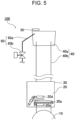
- a general diffusion bleeder 100 has a diffusion pipe 40 formed by an outer pipe 40a and an inner pipe 40b and in which a coke oven gas is distributed and a casing 30 in which an open valve 20a, called a flap, and actuators 20d and 20e, such as cylinders, are provided, and includes a diffusion valve 20 that diffuses the coke oven gas inside a gas collection pipe 10 into the atmosphere.
- the diffusion bleeder 100 is mounted on the upper side of the gas collection pipe 10.
- the diffusion valve 20 is opened by using the actuators 20d and 20e, such as cylinders, when a pressure of the coke oven gas inside the gas collection pipe 10 has a set value, to diffuse the coke oven gas through the diffusion pipe 40 to the outside.
- An upper portion of the diffusion pipe 40 has a double structure that includes the outer pipe 40a in communication with the atmosphere and the inner pipe 40b in communication with a source of the coke oven gas.
- the coke oven gas is pressure-fed from the source into the inner pipe 40b, and a negative pressure generated consequently is used to take in air through a gap between the outer pipe 40a and the inner pipe 40b.
- an ignition-gas supplying device 60 including an ignition-gas supply pipe 60a and an ignition-gas supply valve 60b that are used for supplying a gas (hereinafter, referred to as "ignition gas") for pilot light, and an ignition device 50, such as an igniter.
- ignition gas a gas for pilot light
- ignition device 50 such as an igniter.
- the ignition gas is combusted to serve as pilot light, and the combustible gases in the coke oven gas are combusted to be neutralized.
- the ignition gas is continuously supplied to avoid extinction of fire.
- the diffusion bleeder 100 illustrated in Fig. 5 has a problem that, since the diffusion valve 20 is opened manually or by using the actuators 20d and 20e, such as cylinders, after the pressure of the coke oven gas inside the gas collection pipe 10 has a set value, it takes time to actually open the diffusion valve 20 after diffusion of the coke oven gas is required.
- PTL 1 discloses a configuration in which a counterweight for counteracting a moment generated by the own weight of a diffusion valve is mounted on the diffusion valve to open the valve automatically in response to an increase in the pressure of a coke oven gas inside a gas collection pipe and diffuse the coke oven gas into the atmosphere.
- PTL 2 discloses a configuration in which an injection pipe through which a combustion acceleration gas that accelerates combustion inside a diffusion pipe is provided in a gap between an outer pipe and an inner pipe to accelerate combustion of a coke oven gas.
- the present invention has been made in consideration of such circumstances, and an object of the present invention is to provide a diffusion bleeder and a coke-oven-gas combustion method that are capable of suppressing incomplete combustion of a coke oven gas and suppressing excessive use of electric power and gases by combusting combustible gases contained in the coke oven gas at optimum timing in a coke oven battery.
- a configuration of a diffusion bleeder according to an embodiment of the present invention will be described below.
- Fig. 1 is a sectional view of a heat regenerator 22 and a carbonization chamber 23 of a coke oven battery 21.
- the heat regenerator 22 is disposed in a lower portion of an oven body, and a combustion chamber (not illustrated) and the carbonization chamber 23 are alternately arranged at an upper portion of the heat regenerator 22.
- a coke oven gas that is generated from the carbonization chamber 23 in the process of carbonization of coal passes through an ascension pipe 24 and a bend pipe 25 and gathers in a gas collection pipe 1, which is called a dry main.
- a diffusion valve 2 is opened as an emergency measure, and the coke oven gas inside the gas collection pipe 1 is diffused through a diffusion pipe 4 into the atmosphere.
- Fig. 2 schematically illustrates an example of a diffusion bleeder 12 according to the present embodiment.
- the diffusion bleeder 12 further includes a combustion-acceleration-gas supply device 7, a detector 8, and a control device 11, in addition to the diffusion valve 2 including a counterweight 2f, the diffusion pipe 4, an ignition device 5, and an ignition-gas supply device 6.
- the diffusion pipe 4 connected to the gas collection pipe 1 and through which the coke oven gas is distributed is disposed.
- the ignition-gas supply device 6 supplies an ignition gas to the diffusion pipe 4 and the ignition device 5.
- the combustion-acceleration-gas supply device 7 supplies a gas (hereinafter referred to as "combustion acceleration gas") for accelerating combustion of the coke oven gas.
- the detector 8 detects opening of the diffusion valve 2.
- the control device 11 controls operation of the ignition device 5, the ignition-gas supply device 6, and the combustion-acceleration-gas supply device 7.
- the diffusion pipe 4 has a double structure that includes an outer pipe 4a in communication with the atmosphere and an inner pipe 4b in communication with a source of the coke oven gas through the diffusion valve 2.
- the diffusion valve 2 includes a casing 3 that has an opening through which the coke oven gas passes; an open valve 2a that opens and closes an opening 2c by rotating about a rotary shaft 2b, the open valve 2a being called a flap; an open actuator 2d and a close actuator 2e that rotationally drive the open valve 2a connected to the rotary shaft 2b by a link mechanism or the like; the counterweight 2f that is located opposite the open valve 2a in point symmetry with respect to the rotary shaft 2b and that is provided to counteract a moment generated by the own weight of the open valve 2a; and a striker 2g that is mounted on the counterweight 2f to be interlocked with the counterweight 2f.
- the counterweight 2f is provided to counteract the moment generated by the own weight of the open valve 2a and is configured such that, as a moment acting on the open valve 2a due to the pressure of the coke oven gas is larger than a moment due to the own weight of the open valve 2a when the internal pressure of the gas collection pipe 1 becomes a set pressure, the open valve 2a rotates as indicated by the dotted line in Fig. 2 without actuation of the open actuator 2d, the opening 2c is opened, and the open valve 2a is opened.
- the set pressure means a pressure that corresponds to a value of a weight that is obtained by subtracting the weight of the counterweight 2f from the weight of the open valve 2a. It is also possible to rotate the open valve 2a and open the opening 2c by actuating the open actuator 2d. Then, it is possible by actuating the close actuator 2e to rotate the open valve 2a and close the opening 2c.
- the ignition device 5 is provided at an upper portion of the outer pipe 4a and is constituted by an igniter or the like that is provided for combustion of the coke oven gas inside the diffusion pipe 4.
- the ignition-gas supply device 6 is used to supply a small amount of the coke oven gas (ignition gas) for pilot light for ignition of the coke oven gas to the ignition device 5 and includes an ignition-gas supply pipe 6a and an ignition-gas supply valve 6b.
- the ignition-gas supply pipe 6a is connected at one end thereof to the gas collection pipe 1, and a tip portion at the other end thereof is provided on the inner side of the outer pipe 4a to project in the vicinity of the ignition device 5.
- the ignition gas that is supplied from the tip portion through the ignition-gas supply valve 6b disposed at an intermediate portion of the ignition-gas supply pipe 6a is ignited and combusted by the ignition device 5 and becomes pilot light for ignition of the coke oven gas distributed through the inside of the diffusion pipe 4.
- a combustible gas such as oxygen, may be used as the ignition gas.
- the combustion-acceleration-gas supply device 7 includes a combustion-acceleration-gas supply pipe 7a that is for supplying the combustion acceleration gas for accelerating combustion through a gap between the outer pipe 4a and the inner pipe 4b; the combustion-acceleration-gas supply valve 7b that is disposed at the combustion-acceleration-gas supply pipe 7a and that opens to distribute the combustion acceleration gas; and a compressor 7c for pressure-feeding the combustion acceleration gas.
- the combustion acceleration gas compressed by the compressor 7c flows in together with gases (hereinafter, referred to as "accompanying gases") including a peripheral gas such as air and the like through the gap between the outer pipe 4a and the inner pipe 4b.
- the combustion acceleration gas and the accompanying gases are stirred with the coke oven gas in the diffusion pipe 4, and complete combustion of the coke oven gas is accelerated in the diffusion pipe 4.
- the combustion acceleration gas is not particularly limited as long as the combustion acceleration gas is a gaseous body, the combustion acceleration gas is preferably a non-combustible gas to prevent explosion and incomplete combustion inside the outer pipe 4a.
- a non-combustible gas that contains at least one or more of air, nitrogen gas, and water vapor is preferable.
- nitrogen gas is employed as the combustion acceleration gas, complete combustion of the combustible gas is accelerated since, as described above, oxygen that is contained in the accompanying gases, such as air, together with the nitrogen gas reacts with the combustible gas in the coke oven gas.
- the pilot light for ignition by the ignition device 5 and the ignition-gas supply device 6 triggers the combustion of the coke oven gas in a wide range in the inside of the diffusion pipe 4.
- supplying of the combustion acceleration gas to the inside of the diffusion pipe 4 through the gap between the outer pipe 4a and the inner pipe 4b by the combustion-acceleration-gas supply device 7 also accelerates the combustion of the coke oven gas in a wide range in the inside of the diffusion pipe 4.
- the detector 8 detects opening and closing of the opening 2c by the open valve 2a of the diffusion valve 2 and is constituted by a closure detector 8a that detects a state in which the opening 2c is completely closed and an opening detector 8b that detects a state in which the opening 2c is completely opened.
- the detector 8 is installed at the counterweight 2f located opposite the open valve 2a in point symmetry with respect to the rotary shaft 2b of the diffusion valve 2 and detects the presence of the striker 2g when the striker 2g interlocked with the counterweight 2f enters a region in which the striker 2g is detectable.
- the closure detector 8a is set at a location where the closure detector 8a is able to detect the striker 2g in a state in which the open valve 2a completely closes the opening 2c and where the striker 2g is out of a range in which the closure detector 8a is able to detect the striker 2g when the open valve 2a starts opening of the opening 2c even slightly.
- the opening detector 8b is set at a location where the opening detector 8b is able to detect the striker 2g in a state in which the open valve 2a rotates in a direction away from the opening 2c and reaches an ascent limit and in which the open valve 2a is fully opened and where the striker 2g is out of a region in which the opening detector 8b is able to detect the striker 2g when the open valve 2a rotates in a direction toward the opening 2c and is away from the ascent limit.
- the closure detector 8a and the opening detector 8b each transmit a detection signal to the control device 11 in response to detection of the striker 2g.
- a method of detecting the striker 2g by the detector 8 may be either one of an optical contactless method, such as a laser and a contact method, such as a limit switch.
- the control device 11 controls the ignition-gas supply device 6, the ignition device 5, and the combustion-acceleration-gas supply device 7 and is constituted by a general-purpose information processing device, such as a computer including a CPU and the like or a workstation.
- a general-purpose information processing device such as a computer including a CPU and the like or a workstation.
- One example of the control device 11 illustrated in Fig. 2 is constituted by an ignition control device 11a that controls ignition and combustion of the diffusion bleeder 12 by controlling the ignition device 5 and the ignition-gas supply device 6, and a combustion-acceleration control device 11b that controls supplying of the combustion acceleration gas to the diffusion pipe 4 by controlling the combustion-acceleration-gas supply device 7.
- the control device 11 After receiving the detection signal indicating that the diffusion valve 2 starts to open from the detector 8, the control device 11 transmits a control signal for ordering a start of supplying of the ignition gas to the ignition-gas supply device 6 and then transmits a control signal for ordering an ignition operation to the ignition device 5. After the ignition operation is completed and a detection signal indicating that the diffusion valve 2 is fully opened is received, a control signal for ordering a start of supplying of the combustion acceleration gas is transmitted to the combustion-acceleration-gas supply device 7.
- the ignition control device 11a of the control device 11 receives a detection signal indicating that opening of the diffusion valve 2 is started from the detector 8 (closure detector 8a) (S1). Next, the ignition control device 11a transmits a control signal for ordering valve opening for starting distribution of the ignition gas (S2) to the ignition-gas supply valve 6b of the ignition-gas supply device 6. Further, the ignition control device 11a transmits a control signal for ordering a start of the ignition operation (S3) to the ignition device 5. The ignition control device 11a transmits an ignition-operation completion signal (S4) to the combustion-acceleration control device 11b.
- the combustion-acceleration control device 11b After receiving a detection signal indicating that the diffusion valve 2 is fully opened from the detector 8 (opening detector 8b), the combustion-acceleration control device 11b transmits a control signal for ordering activation of the compressor 7c (S5). Further, the combustion-acceleration control device 11b transmits a control signal for ordering valve opening for starting distribution of the combustion acceleration gas (S6) to the combustion-acceleration-gas supply valve 7b.
- the pilot light for ignition of the coke oven gas is lit by the ignition device 5 and the ignition-gas supply device 6 in response to transmission of the control signals by the ignition control device 11a. It is possible with this pilot light for ignition to achieve stable ignition and combustion of the coke oven gas that flows into the diffusion pipe 4 when the diffusion valve 2 is opened.
- Fig. 3(b) is a flowchart at the time of stopping combustion in the diffusion bleeder 12.
- the ignition control device 11a of the control device 11 receives a detection signal indicating that the open valve 2a completely closes the opening 2c from the detector 8 (closure detector 8a) (S11). In response to this, the ignition control device 11a transmits a control signal for ordering valve closure for stopping distribution of the ignition gas to the ignition-gas supply valve 6b of the ignition-gas supply device 6 (S12). Further, the ignition control device 11a transmits a control signal for ordering a stoppage of the ignition operation to the ignition device 5 (S13). The ignition control device 11a transmits an ignition-operation stop signal to the combustion-acceleration control device 11b (S14).
- the combustion-acceleration control device 11b transmits a control signal for ordering a stoppage of the compressor 7c (S15). Further, the combustion-acceleration control device 11b transmits, after the stoppage of the compressor 7c, a control signal for ordering valve closure for stopping distribution of the combustion acceleration gas to the combustion-acceleration-gas supply valve 7b (S16).
- the configuration illustrated in Fig. 2 is a configuration in which the detection signal from the detector 8 is received by the control device 11 but may be a configuration in which the detection signal from the detector 8 is transmitted as it is to the ignition device 5, the ignition-gas supply device 6, and the combustion-acceleration-gas supply device 7 to control the operation of each of the devices.
- the coke oven gas collected in the gas collection pipe 1 is combusted in the diffusion pipe 4 by performing the following steps.
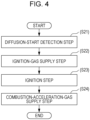
- the method includes a diffusion-start detection step S21, an ignition-gas supply step S22, an ignition step S23, and a combustion-acceleration-gas supply step S24. Each of these steps will be described below.
- the diffusion-start detection step S21 is a step in which a start of opening of the diffusion valve 2 provided between the gas collection pipe 1 and the diffusion pipe 4 is detected when the pressure of the coke oven gas in the gas collection pipe 1 has a set value.
- the control device 11 of the diffusion bleeder 12 executes the step S1 indicated in Fig. 3(a) .
- the ignition-gas supply step S22 is a step in which supplying of the ignition gas for ignition to the inside of the diffusion pipe 4 is started.
- the control device 11 of the diffusion bleeder 12 executes the step S2 indicated in Fig. 3(a) .
- the ignition step S23 is a step in which the ignition gas is lit to serve as the pilot light for ignition and ignite the coke oven gas.
- the control device 11 of the diffusion bleeder 12 executes the step S3 indicated in Fig. 3(a) .
- the combustion-acceleration-gas supply step S24 is a step in which supplying of the combustion acceleration gas that accelerates the combustion of the coke oven gas to the inside of the diffusion pipe 4 is started after completion of the ignition step (S23) and after full opening of the diffusion valve 2 is detected.
- the control device 11 of the diffusion bleeder 12 executes the steps S4, S5, and S6 indicated in Fig. 3(a) .
- the diffusion bleeder 12 As described above, it is possible by using the diffusion bleeder 12 according to the present invention to control the ignition device 5, the ignition-gas supply device 6, and the combustion-acceleration-gas supply device 7 at optimum timing in response to the opening of the diffusion valve 2. It is thus possible to combust the combustible gas contained in the coke oven gas at optimum timing and possible to suppress incomplete combustion of the coke oven gas and suppress excessive use of electric power and gases.
Landscapes
- Engineering & Computer Science (AREA)
- Chemical & Material Sciences (AREA)
- Environmental & Geological Engineering (AREA)
- Oil, Petroleum & Natural Gas (AREA)
- General Engineering & Computer Science (AREA)
- Mechanical Engineering (AREA)
- Organic Chemistry (AREA)
- Materials Engineering (AREA)
- Chemical Kinetics & Catalysis (AREA)
- General Chemical & Material Sciences (AREA)
- Incineration Of Waste (AREA)
- Regulation And Control Of Combustion (AREA)
- Coke Industry (AREA)
Abstract
Description
- The present invention relates to a diffusion bleeder that combusts a coke oven gas and diffuses the coke oven gas into the atmosphere and a coke-oven-gas combustion method using the diffusion bleeder.
- A coke oven battery has a structure in which a heat regenerator is disposed in a lower portion thereof and a carbonization chamber and a combustion chamber are alternately arranged in an upper portion thereof. Here, a fuel gas is combusted in the combustion chamber and coal is carbonized inside the carbonization chamber adjacent to the combustion chamber, thereby obtaining coke.
- A coke oven gas generated by the carbonization of the coal is gathered in an ascension pipe set in each carbonization chamber and is collected in a gas collection pipe called a dry main through a bend pipe. A pressure control valve is provided inside the gas collection pipe, and the pressure inside the gas collection pipe is controlled to be 4 to 5 mmH2O at normal time by the pressure control valve to prevent an explosion caused by entry of air from the outside. The coke oven gas collected in the gas collection pipe is then sent through an intake blower to a gas purification process.
- While the coke oven gas is required to be diffused into the atmosphere in emergency time in which, for example, the intake blower stops due to a trouble such as a pressure increase inside the gas collection pipe or a power failure, the coke oven gas contains, as by-products of incomplete combustion, combustible gases including methane, carbon monoxide, hydrogen, and the like in an uncombusted state and is diffused into the atmosphere after the combustible gases contained in the coke oven gas are combusted to be neutralized. At this time, when incomplete combustion of the combustible gases contained in the coke oven gas occurs, black smoke is generated at the time of diffusion into the atmosphere. Therefore, to diffuse the coke oven gas into the atmosphere, it is required to diffuse the coke oven gas after completely combusting the combustible gases contained in the coke oven gas.
- Here, as an apparatus used for diffusion of the coke oven gas, a diffusion bleeder is widely known. As illustrated in
Fig. 5 , ageneral diffusion bleeder 100 has adiffusion pipe 40 formed by anouter pipe 40a and aninner pipe 40b and in which a coke oven gas is distributed and acasing 30 in which anopen valve 20a, called a flap, andactuators diffusion valve 20 that diffuses the coke oven gas inside agas collection pipe 10 into the atmosphere. Thediffusion bleeder 100 is mounted on the upper side of thegas collection pipe 10. - In the case when the coke oven gas is required to be diffused, the
diffusion valve 20 is opened by using theactuators gas collection pipe 10 has a set value, to diffuse the coke oven gas through thediffusion pipe 40 to the outside. An upper portion of thediffusion pipe 40 has a double structure that includes theouter pipe 40a in communication with the atmosphere and theinner pipe 40b in communication with a source of the coke oven gas. The coke oven gas is pressure-fed from the source into theinner pipe 40b, and a negative pressure generated consequently is used to take in air through a gap between theouter pipe 40a and theinner pipe 40b. In the coke oven gas, components are not constant and calories fluctuate, and therefore, pilot light for ignition is required to combust the coke oven gas stably. Therefore, at an upper portion of theouter pipe 40a, there are provided an ignition-gas supplying device 60 including an ignition-gas supply pipe 60a and an ignition-gas supply valve 60b that are used for supplying a gas (hereinafter, referred to as "ignition gas") for pilot light, and anignition device 50, such as an igniter. The ignition gas is combusted to serve as pilot light, and the combustible gases in the coke oven gas are combusted to be neutralized. During combustion of the coke oven gas, the ignition gas is continuously supplied to avoid extinction of fire. - The
diffusion bleeder 100 illustrated inFig. 5 , however, has a problem that, since thediffusion valve 20 is opened manually or by using theactuators gas collection pipe 10 has a set value, it takes time to actually open thediffusion valve 20 after diffusion of the coke oven gas is required. - In addition, there is a problem that, since the gases are not sufficiently mixed and stirred in the inside of the
diffusion pipe 40 by only taking in air through the gap between theouter pipe 40a and theinner pipe 40b, it is not possible to completely combust the combustible gases in the coke oven gas and a large amount of the combustible gases in an uncombusted state are diffused into the atmosphere. - Regarding such problems,
PTL 1 discloses a configuration in which a counterweight for counteracting a moment generated by the own weight of a diffusion valve is mounted on the diffusion valve to open the valve automatically in response to an increase in the pressure of a coke oven gas inside a gas collection pipe and diffuse the coke oven gas into the atmosphere. - In addition,
PTL 2 discloses a configuration in which an injection pipe through which a combustion acceleration gas that accelerates combustion inside a diffusion pipe is provided in a gap between an outer pipe and an inner pipe to accelerate combustion of a coke oven gas. -
- PTL 1:
Japanese Unexamined Patent Application Publication No. 2006-124508 - PTL 2:
Japanese Unexamined Patent Application Publication No. 2017-96615 - However, with the technologies disclosed in
PTL 1 andPTL 2, there is a time lag between opening of a diffusion valve and activation of an ignition device or injection of a combustion acceleration gas, and a coke oven gas moves in thediffusion pipe 40 during the time lag is not completely combusted and is diffused as it is into the atmosphere. Further, to combust combustible gases in a coke oven gas, it is required at all times to continue activation of an ignition device and injection of a combustion acceleration gas, and there is thus a problem in terms of costs related to the use of electric power and gases. - The present invention has been made in consideration of such circumstances, and an object of the present invention is to provide a diffusion bleeder and a coke-oven-gas combustion method that are capable of suppressing incomplete combustion of a coke oven gas and suppressing excessive use of electric power and gases by combusting combustible gases contained in the coke oven gas at optimum timing in a coke oven battery.
- A summary of the configuration of the present invention for solving the aforementioned problems is as follows.
- [1] A diffusion bleeder that combusts a coke oven gas collected in a gas collection pipe and diffuses the coke oven gas into an atmosphere, the diffusion bleeder including a diffusion pipe connected to the gas collection pipe and through which the coke oven gas is distributed; a diffusion valve that opens to distribute the coke oven gas from the gas collection pipe to the diffusion pipe when a pressure of the coke oven gas in the gas collection pipe has a set value; an ignition device that ignites the coke oven gas; an ignition-gas supply device that supplies an ignition gas for ignition to an inside of the diffusion pipe; a combustion-acceleration-gas supply device that supplies a combustion acceleration gas that accelerates combustion of the coke oven gas to the inside of the diffusion pipe; a detector that detects a start of opening of the diffusion valve; and a control device that controls the ignition-gas supply device, the ignition device, and the combustion-acceleration-gas supply device, in which the control device receives a detection signal indicating that the diffusion valve starts to open from the detector, transmits a control signal for ordering a start of supplying of the ignition gas to the ignition-gas supply device, transmits a control signal for ordering an ignition operation to the ignition device, receives a detection signal indicating that the diffusion valve is fully opened, and transmits a control signal for ordering a start of supplying of the combustion acceleration gas to the combustion-acceleration-gas supply device.
- [2] A coke-oven-gas combustion method in which a coke oven gas collected in a gas collection pipe is combusted in a diffusion pipe, the method including a diffusion-start detection step in which a start of opening of a diffusion valve that is provided between the gas collection pipe and the diffusion pipe is detected when a pressure of the coke oven gas in the gas collection pipe has a set value; an ignition-gas supply step in which supplying of an ignition gas for ignition to an inside of the diffusion pipe is started; an ignition step in which the ignition gas is lit to serve as pilot light for ignition and ignite the coke oven gas; and a combustion-acceleration-gas supply step in which, after completion of the ignition step and after full opening of the diffusion valve is detected, supplying of a combustion acceleration gas that accelerates combustion of the coke oven gas to the inside of the diffusion pipe is started.
- It becomes possible by using the diffusion bleeder and the coke-oven-gas combustion method according to the present invention to activate an ignition device, supply an ignition gas, and supply a combustion acceleration gas in response to opening of a diffusion valve. It is thus possible to combust a combustible gas contained in a coke oven gas at optimum timing and possible to suppress incomplete combustion of the coke oven gas and suppress excessive use of electric power and gases.
-
- [
Fig. 1] Fig. 1 schematically illustrates a sectional view of a heat regenerator and a carbonization chamber of a coke oven battery. - [
Fig. 2] Fig. 2 schematically illustrates an example of a configuration of a diffusion bleeder according to an embodiment of the present invention. - [
Fig. 3] Fig. 3 illustrates an example of a flowchart at the time of starting combustion and stopping combustion in a diffusion bleeder according to an embodiment of the present invention. - [
Fig. 4] Fig. 4 is a flowchart illustrating a flow of processing in a coke-oven-gas combustion method according to an embodiment of the present invention. - [
Fig. 5] Fig. 5 schematically illustrates a configuration of a diffusion bleeder of the related art. Description of Embodiments - A configuration of a diffusion bleeder according to an embodiment of the present invention will be described below.
-
Fig. 1 is a sectional view of aheat regenerator 22 and acarbonization chamber 23 of acoke oven battery 21. In thecoke oven battery 21, theheat regenerator 22 is disposed in a lower portion of an oven body, and a combustion chamber (not illustrated) and thecarbonization chamber 23 are alternately arranged at an upper portion of theheat regenerator 22. A coke oven gas that is generated from thecarbonization chamber 23 in the process of carbonization of coal passes through anascension pipe 24 and abend pipe 25 and gathers in agas collection pipe 1, which is called a dry main. When the pressure inside thegas collection pipe 1 is abnormality increased due to a facility trouble or the like, adiffusion valve 2 is opened as an emergency measure, and the coke oven gas inside thegas collection pipe 1 is diffused through adiffusion pipe 4 into the atmosphere. -
Fig. 2 schematically illustrates an example of adiffusion bleeder 12 according to the present embodiment. As illustrated inFig. 2 , thediffusion bleeder 12 further includes a combustion-acceleration-gas supply device 7, adetector 8, and acontrol device 11, in addition to thediffusion valve 2 including acounterweight 2f, thediffusion pipe 4, anignition device 5, and an ignition-gas supply device 6. - On the upper side of the
diffusion valve 2, thediffusion pipe 4 connected to thegas collection pipe 1 and through which the coke oven gas is distributed is disposed. The ignition-gas supply device 6 supplies an ignition gas to thediffusion pipe 4 and theignition device 5. The combustion-acceleration-gas supply device 7 supplies a gas (hereinafter referred to as "combustion acceleration gas") for accelerating combustion of the coke oven gas. Thedetector 8 detects opening of thediffusion valve 2. Thecontrol device 11 controls operation of theignition device 5, the ignition-gas supply device 6, and the combustion-acceleration-gas supply device 7. - As in the
diffusion bleeder 100 previously described withFig. 5 , thediffusion pipe 4 has a double structure that includes anouter pipe 4a in communication with the atmosphere and aninner pipe 4b in communication with a source of the coke oven gas through thediffusion valve 2. - The
diffusion valve 2 includes acasing 3 that has an opening through which the coke oven gas passes; anopen valve 2a that opens and closes an opening 2c by rotating about arotary shaft 2b, theopen valve 2a being called a flap; anopen actuator 2d and aclose actuator 2e that rotationally drive theopen valve 2a connected to therotary shaft 2b by a link mechanism or the like; thecounterweight 2f that is located opposite theopen valve 2a in point symmetry with respect to therotary shaft 2b and that is provided to counteract a moment generated by the own weight of theopen valve 2a; and astriker 2g that is mounted on thecounterweight 2f to be interlocked with thecounterweight 2f. - The
counterweight 2f is provided to counteract the moment generated by the own weight of theopen valve 2a and is configured such that, as a moment acting on theopen valve 2a due to the pressure of the coke oven gas is larger than a moment due to the own weight of theopen valve 2a when the internal pressure of thegas collection pipe 1 becomes a set pressure, theopen valve 2a rotates as indicated by the dotted line inFig. 2 without actuation of theopen actuator 2d, the opening 2c is opened, and theopen valve 2a is opened. Here, the set pressure means a pressure that corresponds to a value of a weight that is obtained by subtracting the weight of thecounterweight 2f from the weight of theopen valve 2a. It is also possible to rotate theopen valve 2a and open the opening 2c by actuating theopen actuator 2d. Then, it is possible by actuating theclose actuator 2e to rotate theopen valve 2a and close the opening 2c. - The
ignition device 5 is provided at an upper portion of theouter pipe 4a and is constituted by an igniter or the like that is provided for combustion of the coke oven gas inside thediffusion pipe 4. - The ignition-
gas supply device 6 is used to supply a small amount of the coke oven gas (ignition gas) for pilot light for ignition of the coke oven gas to theignition device 5 and includes an ignition-gas supply pipe 6a and an ignition-gas supply valve 6b. The ignition-gas supply pipe 6a is connected at one end thereof to thegas collection pipe 1, and a tip portion at the other end thereof is provided on the inner side of theouter pipe 4a to project in the vicinity of theignition device 5. When the coke oven gas is diffused, the ignition gas that is supplied from the tip portion through the ignition-gas supply valve 6b disposed at an intermediate portion of the ignition-gas supply pipe 6a is ignited and combusted by theignition device 5 and becomes pilot light for ignition of the coke oven gas distributed through the inside of thediffusion pipe 4. As an alternative to the small amount of the coke oven gas, a combustible gas, such as oxygen, may be used as the ignition gas. - The combustion-acceleration-
gas supply device 7 includes a combustion-acceleration-gas supply pipe 7a that is for supplying the combustion acceleration gas for accelerating combustion through a gap between theouter pipe 4a and theinner pipe 4b; the combustion-acceleration-gas supply valve 7b that is disposed at the combustion-acceleration-gas supply pipe 7a and that opens to distribute the combustion acceleration gas; and acompressor 7c for pressure-feeding the combustion acceleration gas. When the coke oven gas is diffused, the combustion acceleration gas compressed by thecompressor 7c flows in together with gases (hereinafter, referred to as "accompanying gases") including a peripheral gas such as air and the like through the gap between theouter pipe 4a and theinner pipe 4b. The combustion acceleration gas and the accompanying gases are stirred with the coke oven gas in thediffusion pipe 4, and complete combustion of the coke oven gas is accelerated in thediffusion pipe 4. - While the combustion acceleration gas is not particularly limited as long as the combustion acceleration gas is a gaseous body, the combustion acceleration gas is preferably a non-combustible gas to prevent explosion and incomplete combustion inside the
outer pipe 4a. In particular, a non-combustible gas that contains at least one or more of air, nitrogen gas, and water vapor is preferable. Even when the nitrogen gas is employed as the combustion acceleration gas, complete combustion of the combustible gas is accelerated since, as described above, oxygen that is contained in the accompanying gases, such as air, together with the nitrogen gas reacts with the combustible gas in the coke oven gas. - Here, the pilot light for ignition by the
ignition device 5 and the ignition-gas supply device 6 triggers the combustion of the coke oven gas in a wide range in the inside of thediffusion pipe 4. In addition, supplying of the combustion acceleration gas to the inside of thediffusion pipe 4 through the gap between theouter pipe 4a and theinner pipe 4b by the combustion-acceleration-gas supply device 7 also accelerates the combustion of the coke oven gas in a wide range in the inside of thediffusion pipe 4. In other words, it is possible to efficiently accelerate the combustion of the coke oven gas in a wide range in the inside of thediffusion pipe 4 by activating theignition device 5 and supplying the ignition gas through the ignition-gas supply device 6 and the combustion acceleration gas through the combustion-acceleration-gas supply device 7 to the inside of thediffusion pipe 4 before the opening 2c starts to be opened by the rotation of theopen valve 2a of thediffusion valve 2 and causes the coke oven gas to flow from thegas collection pipe 1 to the inside of thediffusion pipe 4. - The
detector 8 detects opening and closing of theopening 2c by theopen valve 2a of thediffusion valve 2 and is constituted by aclosure detector 8a that detects a state in which theopening 2c is completely closed and anopening detector 8b that detects a state in which theopening 2c is completely opened. - The
detector 8 is installed at thecounterweight 2f located opposite theopen valve 2a in point symmetry with respect to therotary shaft 2b of thediffusion valve 2 and detects the presence of thestriker 2g when thestriker 2g interlocked with thecounterweight 2f enters a region in which thestriker 2g is detectable. - The
closure detector 8a is set at a location where theclosure detector 8a is able to detect thestriker 2g in a state in which theopen valve 2a completely closes theopening 2c and where thestriker 2g is out of a range in which theclosure detector 8a is able to detect thestriker 2g when theopen valve 2a starts opening of theopening 2c even slightly. - The
opening detector 8b is set at a location where theopening detector 8b is able to detect thestriker 2g in a state in which theopen valve 2a rotates in a direction away from theopening 2c and reaches an ascent limit and in which theopen valve 2a is fully opened and where thestriker 2g is out of a region in which theopening detector 8b is able to detect thestriker 2g when theopen valve 2a rotates in a direction toward theopening 2c and is away from the ascent limit. - The
closure detector 8a and theopening detector 8b each transmit a detection signal to thecontrol device 11 in response to detection of thestriker 2g. A method of detecting thestriker 2g by thedetector 8 may be either one of an optical contactless method, such as a laser and a contact method, such as a limit switch. - The
control device 11 controls the ignition-gas supply device 6, theignition device 5, and the combustion-acceleration-gas supply device 7 and is constituted by a general-purpose information processing device, such as a computer including a CPU and the like or a workstation. One example of thecontrol device 11 illustrated inFig. 2 is constituted by anignition control device 11a that controls ignition and combustion of thediffusion bleeder 12 by controlling theignition device 5 and the ignition-gas supply device 6, and a combustion-acceleration control device 11b that controls supplying of the combustion acceleration gas to thediffusion pipe 4 by controlling the combustion-acceleration-gas supply device 7. - After receiving the detection signal indicating that the
diffusion valve 2 starts to open from thedetector 8, thecontrol device 11 transmits a control signal for ordering a start of supplying of the ignition gas to the ignition-gas supply device 6 and then transmits a control signal for ordering an ignition operation to theignition device 5. After the ignition operation is completed and a detection signal indicating that thediffusion valve 2 is fully opened is received, a control signal for ordering a start of supplying of the combustion acceleration gas is transmitted to the combustion-acceleration-gas supply device 7. - Here, a specific control processing by the
control device 11 at the time of starting of combustion in thediffusion bleeder 12 will be described with a flowchart inFig. 3(a) . Theignition control device 11a of thecontrol device 11 receives a detection signal indicating that opening of thediffusion valve 2 is started from the detector 8 (closure detector 8a) (S1). Next, theignition control device 11a transmits a control signal for ordering valve opening for starting distribution of the ignition gas (S2) to the ignition-gas supply valve 6b of the ignition-gas supply device 6. Further, theignition control device 11a transmits a control signal for ordering a start of the ignition operation (S3) to theignition device 5. Theignition control device 11a transmits an ignition-operation completion signal (S4) to the combustion-acceleration control device 11b. After receiving a detection signal indicating that thediffusion valve 2 is fully opened from the detector 8 (opening detector 8b), the combustion-acceleration control device 11b transmits a control signal for ordering activation of thecompressor 7c (S5). Further, the combustion-acceleration control device 11b transmits a control signal for ordering valve opening for starting distribution of the combustion acceleration gas (S6) to the combustion-acceleration-gas supply valve 7b. - As described above, immediately after the opening of the
diffusion valve 2 is started, the pilot light for ignition of the coke oven gas is lit by theignition device 5 and the ignition-gas supply device 6 in response to transmission of the control signals by theignition control device 11a. It is possible with this pilot light for ignition to achieve stable ignition and combustion of the coke oven gas that flows into thediffusion pipe 4 when thediffusion valve 2 is opened. - Furthermore, since supplying of the combustion acceleration gas by the combustion-acceleration-
gas supply device 7 is started after thediffusion valve 2 is fully opened and the combustion of the coke oven gas is stabilized, it is possible to avoid extinction of fire due to supplying of the combustion acceleration gas pressure-fed in a state in which combustion of the coke oven gas is unstable, and complete combustion of the coke oven gas in thediffusion pipe 4 is accelerated. In other words, it is possible to execute control of theignition device 5, the ignition-gas supply device 6, and the combustion-acceleration-gas supply device 7 at optimum timing after detection of the start of opening of thediffusion valve 2 based on an increase in the internal pressure of thegas collection pipe 1. By controlling the devices at the optimum timing, it is possible to suppress a situation in which a combustible gas contained in the coke oven gas is diffused in an incompletely combusted state into the atmosphere. -
Fig. 3(b) is a flowchart at the time of stopping combustion in thediffusion bleeder 12. Theignition control device 11a of thecontrol device 11 receives a detection signal indicating that theopen valve 2a completely closes theopening 2c from the detector 8 (closure detector 8a) (S11). In response to this, theignition control device 11a transmits a control signal for ordering valve closure for stopping distribution of the ignition gas to the ignition-gas supply valve 6b of the ignition-gas supply device 6 (S12). Further, theignition control device 11a transmits a control signal for ordering a stoppage of the ignition operation to the ignition device 5 (S13). Theignition control device 11a transmits an ignition-operation stop signal to the combustion-acceleration control device 11b (S14). Then, the combustion-acceleration control device 11b transmits a control signal for ordering a stoppage of thecompressor 7c (S15). Further, the combustion-acceleration control device 11b transmits, after the stoppage of thecompressor 7c, a control signal for ordering valve closure for stopping distribution of the combustion acceleration gas to the combustion-acceleration-gas supply valve 7b (S16). - Here, the configuration illustrated in
Fig. 2 is a configuration in which the detection signal from thedetector 8 is received by thecontrol device 11 but may be a configuration in which the detection signal from thedetector 8 is transmitted as it is to theignition device 5, the ignition-gas supply device 6, and the combustion-acceleration-gas supply device 7 to control the operation of each of the devices. - In the coke-oven-gas combustion method according to the present embodiment, the coke oven gas collected in the
gas collection pipe 1 is combusted in thediffusion pipe 4 by performing the following steps. As illustrated inFig. 4 , the method includes a diffusion-start detection step S21, an ignition-gas supply step S22, an ignition step S23, and a combustion-acceleration-gas supply step S24. Each of these steps will be described below. - The diffusion-start detection step S21 is a step in which a start of opening of the
diffusion valve 2 provided between thegas collection pipe 1 and thediffusion pipe 4 is detected when the pressure of the coke oven gas in thegas collection pipe 1 has a set value. In the present embodiment, thecontrol device 11 of thediffusion bleeder 12 executes the step S1 indicated inFig. 3(a) . - The ignition-gas supply step S22 is a step in which supplying of the ignition gas for ignition to the inside of the
diffusion pipe 4 is started. In the present embodiment, thecontrol device 11 of thediffusion bleeder 12 executes the step S2 indicated inFig. 3(a) . - The ignition step S23 is a step in which the ignition gas is lit to serve as the pilot light for ignition and ignite the coke oven gas. In the present embodiment, the
control device 11 of thediffusion bleeder 12 executes the step S3 indicated inFig. 3(a) . - The combustion-acceleration-gas supply step S24 is a step in which supplying of the combustion acceleration gas that accelerates the combustion of the coke oven gas to the inside of the
diffusion pipe 4 is started after completion of the ignition step (S23) and after full opening of thediffusion valve 2 is detected. In the present embodiment, thecontrol device 11 of thediffusion bleeder 12 executes the steps S4, S5, and S6 indicated inFig. 3(a) . - As described above, it is possible by using the
diffusion bleeder 12 according to the present invention to control theignition device 5, the ignition-gas supply device 6, and the combustion-acceleration-gas supply device 7 at optimum timing in response to the opening of thediffusion valve 2. It is thus possible to combust the combustible gas contained in the coke oven gas at optimum timing and possible to suppress incomplete combustion of the coke oven gas and suppress excessive use of electric power and gases. -
- 1
- gas collection pipe
- 2
- diffusion valve
- 3
- casing
- 4
- diffusion pipe
- 5
- ignition device
- 6
- ignition-gas supply device
- 7
- combustion-acceleration-gas supply device
- 8
- detector
- 11
- control device
- 12
- diffusion bleeder
Claims (2)
- A diffusion bleeder that combusts a coke oven gas collected in a gas collection pipe and diffuses the coke oven gas into an atmosphere, the diffusion bleeder comprising:a diffusion pipe connected to the gas collection pipe and through which the coke oven gas is distributed;a diffusion valve that opens to distribute the coke oven gas from the gas collection pipe to the diffusion pipe when a pressure of the coke oven gas in the gas collection pipe has a set value;an ignition device that ignites the coke oven gas;an ignition-gas supply device that supplies an ignition gas for ignition to an inside of the diffusion pipe;a combustion-acceleration-gas supply device that supplies a combustion acceleration gas that accelerates combustion of the coke oven gas to the inside of the diffusion pipe;a detector that detects a start of opening of the diffusion valve; anda control device that controls the ignition-gas supply device, the ignition device, and the combustion-acceleration-gas supply device,wherein the control device receives a detection signal indicating that the diffusion valve starts to open from the detector, transmits a control signal for ordering a start of supplying of the ignition gas to the ignition-gas supply device, transmits a control signal for ordering an ignition operation to the ignition device, receives a detection signal indicating that the diffusion valve is fully opened, and transmits a control signal for ordering a start of supplying of the combustion acceleration gas to the combustion-acceleration-gas supply device.
- A coke-oven-gas combustion method in which a coke oven gas collected in a gas collection pipe is combusted in a diffusion pipe, the method comprising:a diffusion-start detection step in which a start of opening of a diffusion valve that is provided between the gas collection pipe and the diffusion pipe is detected when a pressure of the coke oven gas in the gas collection pipe has a set value;an ignition-gas supply step in which supplying of an ignition gas for ignition to an inside of the diffusion pipe is started;an ignition step in which the ignition gas is lit to serve as pilot light for ignition and ignite the coke oven gas; anda combustion-acceleration-gas supply step in which, after completion of the ignition step and after full opening of the diffusion valve is detected, supplying of a combustion acceleration gas that accelerates combustion of the coke oven gas to the inside of the diffusion pipe is started.
Applications Claiming Priority (2)
| Application Number | Priority Date | Filing Date | Title |
|---|---|---|---|
| JP2021093187 | 2021-06-02 | ||
| PCT/JP2022/020758 WO2022255109A1 (en) | 2021-06-02 | 2022-05-19 | Dissipation bleeder and coke oven gas combustion method |
Publications (2)
| Publication Number | Publication Date |
|---|---|
| EP4350216A1 true EP4350216A1 (en) | 2024-04-10 |
| EP4350216A4 EP4350216A4 (en) | 2024-10-02 |
Family
ID=84323196
Family Applications (1)
| Application Number | Title | Priority Date | Filing Date |
|---|---|---|---|
| EP22815861.4A Pending EP4350216A4 (en) | 2021-06-02 | 2022-05-19 | OUTLET AND COKE OVEN GAS COMBUSTION PROCESS |
Country Status (4)
| Country | Link |
|---|---|
| EP (1) | EP4350216A4 (en) |
| JP (1) | JP7207619B1 (en) |
| TW (1) | TW202307373A (en) |
| WO (1) | WO2022255109A1 (en) |
Families Citing this family (1)
| Publication number | Priority date | Publication date | Assignee | Title |
|---|---|---|---|---|
| CN116622417B (en) * | 2023-05-25 | 2026-02-06 | 珠海市柏克莱能源科技股份有限公司 | Gas supply and distribution system based on low-heating-value gas generator and control method thereof |
Family Cites Families (6)
| Publication number | Priority date | Publication date | Assignee | Title |
|---|---|---|---|---|
| JPS6089619A (en) * | 1983-10-24 | 1985-05-20 | Ishikawajima Harima Heavy Ind Co Ltd | Dissipated gas combustion method in coke dry fire extinguishing equipment |
| JPWO2004081450A1 (en) * | 2003-03-10 | 2006-06-15 | 株式会社 リーテック | Gas combustion control method and gas combustion apparatus |
| JP2006124508A (en) * | 2004-10-28 | 2006-05-18 | Jfe Steel Kk | Coke oven diffusion valve |
| CN103789472A (en) * | 2014-02-11 | 2014-05-14 | 山西太钢不锈钢股份有限公司 | Blast-furnace gas diffusing ignition method |
| JP2017096615A (en) * | 2015-11-18 | 2017-06-01 | Jfeスチール株式会社 | Diffusion breeder |
| CN207112832U (en) * | 2017-07-26 | 2018-03-16 | 柳州钢铁股份有限公司 | Coal oven dithio-gas diffuses and igniter |
-
2022
- 2022-05-19 WO PCT/JP2022/020758 patent/WO2022255109A1/en not_active Ceased
- 2022-05-19 JP JP2022549616A patent/JP7207619B1/en active Active
- 2022-05-19 EP EP22815861.4A patent/EP4350216A4/en active Pending
- 2022-05-26 TW TW111119640A patent/TW202307373A/en unknown
Also Published As
| Publication number | Publication date |
|---|---|
| JPWO2022255109A1 (en) | 2022-12-08 |
| WO2022255109A1 (en) | 2022-12-08 |
| TW202307373A (en) | 2023-02-16 |
| JP7207619B1 (en) | 2023-01-18 |
| EP4350216A4 (en) | 2024-10-02 |
Similar Documents
| Publication | Publication Date | Title |
|---|---|---|
| RU2521179C2 (en) | Gas turbine engine running on lean fuel mix | |
| US8789478B2 (en) | Dry distillation and gasification typed incinerator | |
| US9366435B2 (en) | Ignition torch and pressurized gasification furnace including the same | |
| US5806299A (en) | Process and apparatus for quickly switching over from premix combustion to diffusion combustion in a gas turbine | |
| JP5228511B2 (en) | Pyrolysis equipment | |
| CN102735068B (en) | The combustible protective gas of association is used as method and the industrial furnace of heating gas | |
| JP7207619B1 (en) | Diffusion bleeder and coke oven gas combustion method | |
| CN111706847A (en) | Safe start-up method and burner system for industrial gas boilers | |
| CN109054870B (en) | Fire guide device and working method for coke oven riser | |
| US5653180A (en) | Apparatus for incinerating waste material by dry distillation & gasification | |
| JP3033015B2 (en) | Semi-dry distillation gasification incineration method and apparatus | |
| JP3052755B2 (en) | Ignition method of regenerative burner | |
| US4598541A (en) | Hot gas generator | |
| BR112023023347B1 (en) | Diffusion Trap and Coke Oven Gas Combustion Method | |
| KR102201570B1 (en) | Industrial furnace and combustion control method for industrial furnace | |
| CN220417380U (en) | Ignition device with interlocking protection for gas hot air furnace | |
| KR101198889B1 (en) | Coke oven gas automatic ignition device | |
| KR102354371B1 (en) | The burner structure for the incineration for the toxic gas combustion included in the combustion gas | |
| CN211781151U (en) | Anti-backfire CO after-combustion furnace | |
| CN121067325B (en) | A combustion control system and method for a hydrogen-doped differential intelligent burner | |
| CN215259823U (en) | Dual fuel burner with isolation | |
| KR100199921B1 (en) | Method and apparatus for preheating of gasification equipment | |
| EP1956292A1 (en) | Secondary combustion method and unit in incineration system | |
| CN118705902B (en) | A safety control device for preventing flash explosion of hydrogen heating furnace for waste mineral oil treatment | |
| CN217559876U (en) | Safety controller for realizing fuel combustion |
Legal Events
| Date | Code | Title | Description |
|---|---|---|---|
| STAA | Information on the status of an ep patent application or granted ep patent |
Free format text: STATUS: THE INTERNATIONAL PUBLICATION HAS BEEN MADE |
|
| PUAI | Public reference made under article 153(3) epc to a published international application that has entered the european phase |
Free format text: ORIGINAL CODE: 0009012 |
|
| STAA | Information on the status of an ep patent application or granted ep patent |
Free format text: STATUS: REQUEST FOR EXAMINATION WAS MADE |
|
| 17P | Request for examination filed |
Effective date: 20231120 |
|
| AK | Designated contracting states |
Kind code of ref document: A1 Designated state(s): AL AT BE BG CH CY CZ DE DK EE ES FI FR GB GR HR HU IE IS IT LI LT LU LV MC MK MT NL NO PL PT RO RS SE SI SK SM TR |
|
| REG | Reference to a national code |
Ref country code: DE Ref legal event code: R079 Free format text: PREVIOUS MAIN CLASS: F23G0007080000 Ipc: C10B0027060000 |
|
| DAV | Request for validation of the european patent (deleted) | ||
| DAX | Request for extension of the european patent (deleted) | ||
| A4 | Supplementary search report drawn up and despatched |
Effective date: 20240902 |
|
| RIC1 | Information provided on ipc code assigned before grant |
Ipc: C10B 41/08 20060101ALI20240827BHEP Ipc: F23G 5/50 20060101ALI20240827BHEP Ipc: F23G 7/06 20060101ALI20240827BHEP Ipc: F23G 7/08 20060101ALI20240827BHEP Ipc: C10B 45/00 20060101ALI20240827BHEP Ipc: C10B 27/06 20060101AFI20240827BHEP |