EP4350206A1 - Planar illumination device - Google Patents
Planar illumination device Download PDFInfo
- Publication number
- EP4350206A1 EP4350206A1 EP22809318.3A EP22809318A EP4350206A1 EP 4350206 A1 EP4350206 A1 EP 4350206A1 EP 22809318 A EP22809318 A EP 22809318A EP 4350206 A1 EP4350206 A1 EP 4350206A1
- Authority
- EP
- European Patent Office
- Prior art keywords
- lens
- axial direction
- illumination device
- light
- planar illumination
- Prior art date
- Legal status (The legal status is an assumption and is not a legal conclusion. Google has not performed a legal analysis and makes no representation as to the accuracy of the status listed.)
- Pending
Links
Images





Classifications
-
- G—PHYSICS
- G02—OPTICS
- G02F—OPTICAL DEVICES OR ARRANGEMENTS FOR THE CONTROL OF LIGHT BY MODIFICATION OF THE OPTICAL PROPERTIES OF THE MEDIA OF THE ELEMENTS INVOLVED THEREIN; NON-LINEAR OPTICS; FREQUENCY-CHANGING OF LIGHT; OPTICAL LOGIC ELEMENTS; OPTICAL ANALOGUE/DIGITAL CONVERTERS
- G02F1/00—Devices or arrangements for the control of the intensity, colour, phase, polarisation or direction of light arriving from an independent light source, e.g. switching, gating or modulating; Non-linear optics
- G02F1/01—Devices or arrangements for the control of the intensity, colour, phase, polarisation or direction of light arriving from an independent light source, e.g. switching, gating or modulating; Non-linear optics for the control of the intensity, phase, polarisation or colour
- G02F1/13—Devices or arrangements for the control of the intensity, colour, phase, polarisation or direction of light arriving from an independent light source, e.g. switching, gating or modulating; Non-linear optics for the control of the intensity, phase, polarisation or colour based on liquid crystals, e.g. single liquid crystal display cells
- G02F1/133—Constructional arrangements; Operation of liquid crystal cells; Circuit arrangements
- G02F1/1333—Constructional arrangements; Manufacturing methods
- G02F1/1335—Structural association of cells with optical devices, e.g. polarisers or reflectors
- G02F1/1336—Illuminating devices
- G02F1/133602—Direct backlight
- G02F1/133603—Direct backlight with LEDs
-
- F—MECHANICAL ENGINEERING; LIGHTING; HEATING; WEAPONS; BLASTING
- F21—LIGHTING
- F21V—FUNCTIONAL FEATURES OR DETAILS OF LIGHTING DEVICES OR SYSTEMS THEREOF; STRUCTURAL COMBINATIONS OF LIGHTING DEVICES WITH OTHER ARTICLES, NOT OTHERWISE PROVIDED FOR
- F21V5/00—Refractors for light sources
- F21V5/007—Array of lenses or refractors for a cluster of light sources, e.g. for arrangement of multiple light sources in one plane
-
- F—MECHANICAL ENGINEERING; LIGHTING; HEATING; WEAPONS; BLASTING
- F21—LIGHTING
- F21S—NON-PORTABLE LIGHTING DEVICES; SYSTEMS THEREOF; VEHICLE LIGHTING DEVICES SPECIALLY ADAPTED FOR VEHICLE EXTERIORS
- F21S2/00—Systems of lighting devices, not provided for in main groups F21S4/00 - F21S10/00 or F21S19/00, e.g. of modular construction
-
- F—MECHANICAL ENGINEERING; LIGHTING; HEATING; WEAPONS; BLASTING
- F21—LIGHTING
- F21V—FUNCTIONAL FEATURES OR DETAILS OF LIGHTING DEVICES OR SYSTEMS THEREOF; STRUCTURAL COMBINATIONS OF LIGHTING DEVICES WITH OTHER ARTICLES, NOT OTHERWISE PROVIDED FOR
- F21V5/00—Refractors for light sources
- F21V5/04—Refractors for light sources of lens shape
-
- F—MECHANICAL ENGINEERING; LIGHTING; HEATING; WEAPONS; BLASTING
- F21—LIGHTING
- F21V—FUNCTIONAL FEATURES OR DETAILS OF LIGHTING DEVICES OR SYSTEMS THEREOF; STRUCTURAL COMBINATIONS OF LIGHTING DEVICES WITH OTHER ARTICLES, NOT OTHERWISE PROVIDED FOR
- F21V5/00—Refractors for light sources
- F21V5/04—Refractors for light sources of lens shape
- F21V5/045—Refractors for light sources of lens shape the lens having discontinuous faces, e.g. Fresnel lenses
-
- F—MECHANICAL ENGINEERING; LIGHTING; HEATING; WEAPONS; BLASTING
- F21—LIGHTING
- F21V—FUNCTIONAL FEATURES OR DETAILS OF LIGHTING DEVICES OR SYSTEMS THEREOF; STRUCTURAL COMBINATIONS OF LIGHTING DEVICES WITH OTHER ARTICLES, NOT OTHERWISE PROVIDED FOR
- F21V7/00—Reflectors for light sources
- F21V7/0083—Array of reflectors for a cluster of light sources, e.g. arrangement of multiple light sources in one plane
-
- G—PHYSICS
- G02—OPTICS
- G02F—OPTICAL DEVICES OR ARRANGEMENTS FOR THE CONTROL OF LIGHT BY MODIFICATION OF THE OPTICAL PROPERTIES OF THE MEDIA OF THE ELEMENTS INVOLVED THEREIN; NON-LINEAR OPTICS; FREQUENCY-CHANGING OF LIGHT; OPTICAL LOGIC ELEMENTS; OPTICAL ANALOGUE/DIGITAL CONVERTERS
- G02F1/00—Devices or arrangements for the control of the intensity, colour, phase, polarisation or direction of light arriving from an independent light source, e.g. switching, gating or modulating; Non-linear optics
- G02F1/01—Devices or arrangements for the control of the intensity, colour, phase, polarisation or direction of light arriving from an independent light source, e.g. switching, gating or modulating; Non-linear optics for the control of the intensity, phase, polarisation or colour
- G02F1/13—Devices or arrangements for the control of the intensity, colour, phase, polarisation or direction of light arriving from an independent light source, e.g. switching, gating or modulating; Non-linear optics for the control of the intensity, phase, polarisation or colour based on liquid crystals, e.g. single liquid crystal display cells
- G02F1/133—Constructional arrangements; Operation of liquid crystal cells; Circuit arrangements
- G02F1/1333—Constructional arrangements; Manufacturing methods
- G02F1/1335—Structural association of cells with optical devices, e.g. polarisers or reflectors
- G02F1/1336—Illuminating devices
- G02F1/133602—Direct backlight
- G02F1/133605—Direct backlight including specially adapted reflectors
-
- G—PHYSICS
- G02—OPTICS
- G02F—OPTICAL DEVICES OR ARRANGEMENTS FOR THE CONTROL OF LIGHT BY MODIFICATION OF THE OPTICAL PROPERTIES OF THE MEDIA OF THE ELEMENTS INVOLVED THEREIN; NON-LINEAR OPTICS; FREQUENCY-CHANGING OF LIGHT; OPTICAL LOGIC ELEMENTS; OPTICAL ANALOGUE/DIGITAL CONVERTERS
- G02F1/00—Devices or arrangements for the control of the intensity, colour, phase, polarisation or direction of light arriving from an independent light source, e.g. switching, gating or modulating; Non-linear optics
- G02F1/01—Devices or arrangements for the control of the intensity, colour, phase, polarisation or direction of light arriving from an independent light source, e.g. switching, gating or modulating; Non-linear optics for the control of the intensity, phase, polarisation or colour
- G02F1/13—Devices or arrangements for the control of the intensity, colour, phase, polarisation or direction of light arriving from an independent light source, e.g. switching, gating or modulating; Non-linear optics for the control of the intensity, phase, polarisation or colour based on liquid crystals, e.g. single liquid crystal display cells
- G02F1/133—Constructional arrangements; Operation of liquid crystal cells; Circuit arrangements
- G02F1/1333—Constructional arrangements; Manufacturing methods
- G02F1/1335—Structural association of cells with optical devices, e.g. polarisers or reflectors
- G02F1/1336—Illuminating devices
- G02F1/133602—Direct backlight
- G02F1/133606—Direct backlight including a specially adapted diffusing, scattering or light controlling members
- G02F1/133607—Direct backlight including a specially adapted diffusing, scattering or light controlling members the light controlling member including light directing or refracting elements, e.g. prisms or lenses
-
- G—PHYSICS
- G02—OPTICS
- G02F—OPTICAL DEVICES OR ARRANGEMENTS FOR THE CONTROL OF LIGHT BY MODIFICATION OF THE OPTICAL PROPERTIES OF THE MEDIA OF THE ELEMENTS INVOLVED THEREIN; NON-LINEAR OPTICS; FREQUENCY-CHANGING OF LIGHT; OPTICAL LOGIC ELEMENTS; OPTICAL ANALOGUE/DIGITAL CONVERTERS
- G02F1/00—Devices or arrangements for the control of the intensity, colour, phase, polarisation or direction of light arriving from an independent light source, e.g. switching, gating or modulating; Non-linear optics
- G02F1/01—Devices or arrangements for the control of the intensity, colour, phase, polarisation or direction of light arriving from an independent light source, e.g. switching, gating or modulating; Non-linear optics for the control of the intensity, phase, polarisation or colour
- G02F1/13—Devices or arrangements for the control of the intensity, colour, phase, polarisation or direction of light arriving from an independent light source, e.g. switching, gating or modulating; Non-linear optics for the control of the intensity, phase, polarisation or colour based on liquid crystals, e.g. single liquid crystal display cells
- G02F1/133—Constructional arrangements; Operation of liquid crystal cells; Circuit arrangements
- G02F1/1333—Constructional arrangements; Manufacturing methods
- G02F1/1335—Structural association of cells with optical devices, e.g. polarisers or reflectors
- G02F1/1336—Illuminating devices
- G02F1/133602—Direct backlight
- G02F1/133611—Direct backlight including means for improving the brightness uniformity
-
- F—MECHANICAL ENGINEERING; LIGHTING; HEATING; WEAPONS; BLASTING
- F21—LIGHTING
- F21Y—INDEXING SCHEME ASSOCIATED WITH SUBCLASSES F21K, F21L, F21S and F21V, RELATING TO THE FORM OR THE KIND OF THE LIGHT SOURCES OR OF THE COLOUR OF THE LIGHT EMITTED
- F21Y2105/00—Planar light sources
- F21Y2105/10—Planar light sources comprising a two-dimensional [2D] array of point-like light-generating elements
-
- F—MECHANICAL ENGINEERING; LIGHTING; HEATING; WEAPONS; BLASTING
- F21—LIGHTING
- F21Y—INDEXING SCHEME ASSOCIATED WITH SUBCLASSES F21K, F21L, F21S and F21V, RELATING TO THE FORM OR THE KIND OF THE LIGHT SOURCES OR OF THE COLOUR OF THE LIGHT EMITTED
- F21Y2113/00—Combination of light sources
-
- F—MECHANICAL ENGINEERING; LIGHTING; HEATING; WEAPONS; BLASTING
- F21—LIGHTING
- F21Y—INDEXING SCHEME ASSOCIATED WITH SUBCLASSES F21K, F21L, F21S and F21V, RELATING TO THE FORM OR THE KIND OF THE LIGHT SOURCES OR OF THE COLOUR OF THE LIGHT EMITTED
- F21Y2115/00—Light-generating elements of semiconductor light sources
- F21Y2115/10—Light-emitting diodes [LED]
Definitions
- the present invention relates to a planar illumination device.
- the present invention has been made in view of the above, and an object of the present invention is to provide a planar illumination device capable of achieving required light distribution characteristics while ensuring high luminance.
- a planar illumination device includes a substrate, a first optical element, and a second optical element.
- a plurality of light sources are two dimensionally disposed at the substrate.
- the first optical element is disposed at an emission side of the plurality of light sources and condenses light emitted from the plurality of light sources.
- the second optical element inclines a light distribution of the light condensed by the first optical element with respect to the first axial direction.
- planar illumination device can achieve required light distribution characteristics while ensuring high luminance.
- a planar illumination device is described below with reference to the drawings. Further, the present invention is not limited to the embodiment. Furthermore, the dimensional relationships between elements, proportions of the elements, and the like in the drawings may differ from reality. The drawings may include parts having mutually different dimensional relationships and proportions. Furthermore, the contents described in one embodiment or modification examples are applied in principle to other embodiments or modification examples.
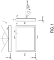
- FIG. 1 is a view for explaining light distribution characteristics required for a planar illumination device 1 according to the embodiment.
- FIG. 1 is an external view of the planar illumination device 1 according to the embodiment, and in FIG. 1 , for convenience, a light emitting surface of the planar illumination device 1 is in an X-Y plane, and a thickness direction of the planar illumination device 1 is a Z direction.
- the planar illumination device 1 has a substantially rectangular plate-shaped outer shape, and light is emitted from the inside of an opening 9a of a frame 9.
- the outer shape of the planar illumination device 1 is not limited to the rectangular plate shape illustrated in the drawing.
- the "optical axis shift" illustrated in the figure means inclination of the optical axis.
- the optical axis is inclined to the negative direction side of the Y-axis of the planar illumination device 1 (obliquely lower right in the drawing), and it is illustrated that a narrow visual field range is required.
- a wide visual field range is required with the normal direction of the light emitting surface as the optical axis.
- the planar illumination device 1 includes a first optical element that condenses light emitted from the light source, and a second optical element that inclines a light distribution of the light condensed by the first optical element with respect to the Y-axis direction.
- the Y-axis direction is an example of a first axial direction.
- the embodiment can also be applied to a case where the first axial direction is the X-axis direction.
- a configuration example of the planar illumination device 1 of the embodiment will be described in detail.
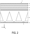
- FIG. 2 is a view for explaining an outline of the planar illumination device illustrated in FIG. 1 .
- FIG. 2 is a simplified A-A cross-sectional view of the planar illumination device 1 illustrated in FIG. 1 .
- the frame 9 is omitted.
- the A-A cross-sectional view may be referred to as a longitudinal cross-sectional view.
- a B-B cross-sectional view of the planar illumination device 1 illustrated in FIG. 1 may be referred to as a transverse cross-sectional view.
- a plurality of light sources 3 such as light emitting diodes (LEDs) are disposed at a substrate 2.
- the disposed plurality of light sources 3 are illustrated in the Y-axis direction, but the plurality of light sources 3 are also disposed in the X-axis direction (see FIG. 4 described below). That is, the plurality of light sources 3 are two dimensionally disposed at the substrate 2.
- Each of the plurality of light sources 3 is individually driven, and can cope with so-called local dimming.
- a condenser lens 5 provided with a first optical element for condensing the light emitted from the plurality of light sources 3 is disposed at the emission side of the plurality of light sources 3, and a light distribution lens 6 provided with a second optical element for inclining the light distribution of the light condensed by the condenser lens 5 with respect to the Y-axis direction is disposed.
- the condenser lens 5 and the light distribution lens 6 will be described with reference to FIGS. 3 and 4 .
- FIG. 3 is a perspective view schematically illustrating the planar illumination device 1 illustrated in FIG. 1
- FIG. 4 is an A-A cross-sectional view and a B-B cross-sectional view of the planar illumination device illustrated in FIG. 1
- the left drawing of FIG. 4 is a longitudinal cross-sectional view
- the right drawing of FIG. 4 is a transverse cross-sectional view
- the longitudinal cross-sectional view of FIG. 4 schematically illustrates the behavior of the light beam in the Y-axis direction
- the transverse cross-sectional view of FIG. 4 schematically illustrates the behavior of the light beam in the X-axis direction.
- the condenser lens 5 extends in the X-axis direction orthogonal to the Y-axis direction, and includes, as a first optical element, a linear Fresnel lens 5a condensing light emitted from the plurality of light sources 3 in the Y-axis direction.
- the linear Fresnel lens 5a is provided at the surface opposite to the surface opposing the substrate 2 (the emission side surface of the condenser lens 5).
- the X-axis direction is an example of a second axial direction.
- the linear Fresnel lens 5a has a prism structure such that a cylindrical convex lens is used as a Fresnel lens, and has a groove extending in the X-axis direction.
- grooves are periodically formed in accordance with the pitch (the pitch in the Y-axis direction) of the light sources 3 disposed directly below.
- the light distribution lens 6 has a linear prism 6a extending in the X-axis direction as a second optical element for inclining the light distribution of the light condensed by the condenser lens 5 with respect to the Y-axis direction.
- the linear prism 6a is provided at the surface opposite to the surface opposing the condenser lens 5 (the emission side surface of the light distribution lens 6).
- the linear prism 6a has a substantially triangular prism structure extending in the X-axis direction, and is continuously disposed in the Y-axis direction. As a result, a groove extending in the X-axis direction is formed at the emission side surface of the light distribution lens 6.
- the cross-sectional shape of the Y-Z plane of the linear prism 6a is a triangle, and the base angle of the side connecting the vertex and the point on the positive direction side of the Y-axis of the base is smaller than the base angle of the side connecting the vertex and the point on the negative direction side of the Y-axis of the base.
- the light emitted from the light source 3 enters the condenser lens 5, is refracted by the linear Fresnel lens 5a provided at the upper surface of the condenser lens 5, and is emitted as substantially parallel light.
- the parallel light emitted from the condenser lens 5 enters the light distribution lens 6, and is emitted with the optical axis being inclined by the linear prism 6a provided at the upper surface of the light distribution lens 6.
- the light emitted from the light source 3 enters the condenser lens 5, and is emitted without being substantially refracted by the linear Fresnel lens 5a provided at the upper surface of the condenser lens 5.
- the light emitted from the condenser lens 5 enters the light distribution lens 6, and is emitted without being substantially refracted by the linear prism 6a provided at the upper surface of the light distribution lens 6.
- the condenser lens 5 condenses the light emitted from the plurality of light sources 3 and causes the light to efficiently enter the light distribution lens 6 as substantially parallel light, and the light distribution lens 6 causes the light to be emitted with the optical axis of the incident light inclined.
- the planar illumination device 1 can realize the required light distribution characteristics with high luminance.
- the condenser lens 5 of the embodiment is not provided with a linear Fresnel lens extending in the Y-axis direction, and the light distribution lens 6 is not provided with a linear prism extending in the Y-axis direction.
- the condenser lens 5 of the embodiment is not provided with a linear Fresnel lens extending in the Y-axis direction, and the light distribution lens 6 is not provided with a linear prism extending in the Y-axis direction.
- the visual field range adjustment lens 7 is disposed at the emission side of the light distribution lens 6 in order to adjust the light emitted from the light distribution lens 6 to a required visual field range.
- the visual field range adjustment lens 7 includes a first lenticular lens 7a provided at a surface opposing the light distribution lens 6 (a surface on the incident side), and a second lenticular lens 7b provided at a surface opposite to the surface opposing the light distribution lens 6 (a surface on the emission side).
- the first lenticular lens 7a extends in the X-axis direction and adjusts the visual field range in the Y-axis direction.
- the first lenticular lens 7a has a semi-cylindrical type fine prism structure extending in the X-axis direction.
- the second lenticular lens 7b extends in the Y-axis direction and adjusts the luminance distribution in the X-axis direction.
- the second lenticular lens 7b has a semi-cylindrical type fine prism structure extending in the Y-axis direction.
- the embodiment it is possible to control the light distribution to the target visual field range while ensuring high luminance and uniformity by combining the linear Fresnel lens for condensing light, the linear prism for inclining the light to the target optical axis, and the lenticular lens for adjusting the visual field range and the luminance distribution by condensing and diffusing the light.
- the planar illumination device 1 may have a diffusion sheet 8 disposed at the emission side of the visual field range adjustment lens 7 as illustrated in FIG. 2 .
- the diffusion sheet 8 is useful for eliminating striped unevenness or the like caused by the first lenticular lens 7a and the second lenticular lens 7b.
- the planar illumination device 1 is a direct-type backlight
- the reflector 4 is disposed between the plurality of light sources 3 and the condenser lens 5 in order to cause the light emitted by the plurality of light sources 3 to efficiently enter the condenser lens 5.
- the reflector 4 is formed such that openings 4b respectively corresponding to the plurality of light sources 3 are disposed, and has a wall part 4c such that a wall surface surrounding the opening 4b serves as a reflecting surface 4a.
- the reflector 4 has four reflecting surfaces 4a surrounding the openings 4b.
- the planar illumination device 1 of the embodiment is required to have the visual field characteristics of a wide visual field in the X-axis direction and a narrow visual field in the Y-axis direction.
- visual field characteristics are realized mainly by controlling the optical characteristics by the lens function of the condenser lens 5, the light distribution lens 6, the visual field range adjustment lens 7, and the like described above.
- the visual field characteristics obtained through the lens may change depending on the structure of the reflector 4 located between the light source 3 and the lens.
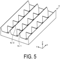
- FIG. 5 is a perspective view of the reflector illustrated in FIG. 3
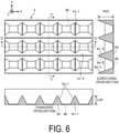
- FIG. 6 is a front view, a C-C cross-sectional view (longitudinal cross section), and a D-D cross-sectional view (transverse cross section) of the reflector illustrated in FIG. 3 .
- the wall part 4c has a shape such that a plurality of first wall parts 4c-1 extending in the Y-axis direction and a plurality of second wall parts 4c-2 extending in the X-axis direction are assembled in a lattice shape.
- the wall part 4c is assembled such that the bottom surface of the first wall parts 4c-1 and the bottom surface of the second wall parts 4c-2 are flush with each other.
- the reflecting surface 4a is a wall surface of the wall part 4c.
- the two reflecting surfaces 4a-1 opposing each other between the two first wall parts 4c-1 adjacent to each other in the X-axis direction are inclined to be separated from each other toward the Z-axis positive direction.
- the reflector 4 is formed of, for example, a white resin or the like in order to enhance a reflection effect.
- the reflector 4 of the embodiment is a molded article formed by injection molding.
- the height of the first wall part 4c-1 is defined by the visual field range in the X-axis direction
- the height of the second wall part 4c-2 is defined by the visual field range in the Y-axis direction.
- the height of the second wall part 4c-2 is increased as illustrated in the longitudinal cross section of FIG. 6 .
- Increasing the height of the second wall part 4c-2 also serves to block light entering the linear Fresnel lens 5a of the adjacent segment, thereby avoiding the occurrence of unintended light distribution.
- the wide light distribution component from the light source 3 is used without being blocked by reducing the height of the first wall part 4c-1.
- the height of the second wall part 4c-2 extending in the X-axis direction (longitudinal direction) is greater than the height of the first wall part 4c-1 extending in the Y-axis direction (lateral direction).
- the reflector 4 of the embodiment is disposed such that the opening 4b is located at the emission side with respect to the light emitting surface of the light source 3.
- the light emitting surface of the light source 3 corresponds to the upper surface of the light source 3.
- the bottom surface 4d of the wall part 4c of the reflector 4 is disposed in a state of being floated from the substrate 2 to be located at a position higher than the light emitting surface of the light source 3.
- the uniaxial linear Fresnel lens 5a extending in the longitudinal direction (X-axis direction) of the substrate 2 is employed in order to condense light only in the lateral direction (Y-axis direction) of the substrate 2.
- the lens misalignment in the long-side direction can be ignored.
- the lenticular lenses are provided in both the X-axis direction and the Y-axis direction.
- the lenticular lenses have the same shape pattern, it is not necessary to take the lens position deviation into account.
- the wall part 4c of the reflector 4 and the light source 3 are close to each other, and the reflector 4 and the light source 3 may interfere with each other when the reflector 4 and the light source 3 expand and contract.
- the opening 4b of the reflector 4 is disposed at a position higher than the light emitting surface of the light source 3, even if the reflector 4 and the light source 3 expand and contract, there is no possibility of contact between the wall part 4c of the reflector 4 and the light source 3.
- the size of the opening 4b of the reflector 4 can be made smaller than the outer periphery of the light source 3 as long as the opening 4b is larger than the light emitting surface of the light source 3 in the top view. That is, in the embodiment, the size of the opening 4b can be reduced.
- the size of the bottom surface 4d can be increased, and as a result, the height of the wall part 4c of the reflector 4 formed by injection molding can be increased. For this reason, in the embodiment, it is possible to obtain effects of high contrast at the time of local dimming and removal of unnecessary light distribution.
- planar illumination device 1 described in the above embodiment is merely an example, and various modifications can be made. Hereinafter, modification examples of the planar illumination device 1 will be described.
- the planar illumination device 1 of the first modification example has the same prism structure (the linear Fresnel lens 5a, the linear prism 6a, the first lenticular lens 7a, and the second lenticular lens 7b) as the structure of the embodiment, but the arrangement of each prism structure is different from the arrangement of the embodiment.
- FIG. 7 is a view for explaining the first modification example.
- the planar illumination device 1 of the first modification example includes, as a first lens, the condenser lens 5 such that the linear Fresnel lens 5a is provided at the surface opposite to the surface opposing the substrate 2, as a first lens, as in the embodiment.
- the planar illumination device 1 of the first modification example includes a second lens 60 and a third lens 70.
- the second lenticular lens 7b is provided at a surface opposing the first lens (the condenser lens 5), and a linear prism 6a extending in the X-axis direction is provided at a surface opposite to the surface opposing the first lens (the condenser lens 5).
- the first lenticular lens 7a is provided at a surface opposing the second lens 60.
- the light emitted from the light source 3 is condensed at the emission surface of the light distribution lens 5 (first lens) and becomes substantially parallel light, the optical axis is inclined at the emission surface of the second lens 60, and the visual field range is adjusted on the incident surface of the third lens 70.
- the luminance distribution of the light emitted from the light source 3 is adjusted by the incident surface of the second lens 60 in the X-axis direction. Even in such a configuration order of the lenses, as in the embodiment, it is possible to realize the required light distribution characteristics while ensuring high luminance.
- a diffusion surface 80 is formed at a surface opposite to a surface opposing the second lens 60.
- the diffusion surface 80 having the same function as the diffusion sheet 8 can be formed at the upper surface of the third lens 70, and the number of components can be reduced.
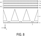
- the planar illumination device 1 of the second modification example has the same prism structure (the linear Fresnel lens 5a, the linear prism 6a, the first lenticular lens 7a, and the second lenticular lens 7b) as the structure of the embodiment, but the arrangement of each prism structures and the number of lenses are different from those of the embodiment.
- FIG. 8 is a view for explaining the second modification example.
- the planar illumination device 1 of the second modification example includes a first lens 51 and a second lens 61.
- the linear Fresnel lens 5a is provided at a surface opposing the substrate 2
- the linear prism 6a is provided at a surface opposite to the surface opposing the substrate 2.
- the second lens 61 is disposed at the emission side of the first lens 51
- the second lenticular lens 7b is provided at the surface opposing the first lens
- the first lenticular lens 7a is provided at the surface opposite to the surface opposing the first lens 51.
- the light emitted from the light source 3 is condensed at the incident surface of the first lens 51 and becomes substantially parallel light, the optical axis is inclined at the emission surface of the first lens 51, and the visual field range is adjusted on the emission surface of the second lens 61.
- the luminance distribution of the light emitted from the light source 3 is adjusted by the incident surface of the second lens 61 in the X-axis direction. Even in such a configuration order of the lenses, as in the embodiment, it is possible to realize the required light distribution characteristics while ensuring high luminance.
- the planar illumination device 1 of the third modification example is constituted by two lenses as in the second modification example, and has prisms (the linear Fresnel lens 5a, the first lenticular lens 7a, and the second lenticular lens 7b) similar to the prisms of the embodiment, but the shape of the linear prism for shifting the optical axis is different from the shape of the linear prism 6a.
- FIG. 9 is a view for explaining the third modification example.
- the planar illumination device 1 of the third modification example includes a first lens 52 and a second lens 62.
- the linear Fresnel lens 5a is provided at a surface opposing the substrate 2
- the second lenticular lens 7b is provided at a surface opposite to the surface opposing the substrate 2.
- the second lens 62 has a linear prism 62a extending in the X-axis direction as a second optical element
- the linear prism 62a is provided at a surface opposing the first lens 52
- the first lenticular lens 7a is provided at a surface opposite to the surface opposing the first lens 52.
- the linear prism 62a has a substantially triangular prism structure extending in the X-axis direction, and is continuously disposed in the Y-axis direction.
- the cross-sectional shape of the Y-Z plane of the linear prism 62a is an inverted triangle, and the base angle of the side connecting the vertex and the point on the positive direction side of the Y-axis of the base is greater than the base angle of the side connecting the vertex and the point on the negative direction side of the Y-axis of the base.
- the light emitted from the light source 3 is condensed at the incident surface of the first lens 52 and becomes substantially parallel light, the optical axis is inclined at the incident surface of the second lens 62, and the visual field range is adjusted on the emission surface of the second lens 62.
- the luminance distribution of the light emitted from the light source 3 is adjusted by the emission surface of the first lens 52 in the X-axis direction. Even in such a configuration order of the lenses, as in the embodiment, it is possible to realize the required light distribution characteristics while ensuring high luminance.
- the lens configuration is not limited to Modification Examples 1 to 3 described above.
- the second lenticular lens 7b may be provided at the incident surface, and the linear Fresnel lens 5a may be provided at the emission surface.
- the bottom surface of the reflector 4 is disposed at a position higher than the light emitting surface of the light source 3 in the above-described embodiment and Modification Examples 1 to 3, the bottom surface of the reflector 4 may be grounded to the substrate 2 as long as interference between the reflector 4 and the light source 3 can be avoided and the visual field range can be adjusted.
- FIG. 10 is a view for explaining the fourth modification example.
- the height of the first wall part 4c-1 is adjusted in accordance with the visual field range in the X-axis direction
- the height of the second wall part 4c-2 is adjusted in accordance with the visual field range in the Y-axis direction.
- the height of the first wall part 4c-1 and the height of the second wall part 4c-2 are the same.
- FIG. 11 is a view for explaining the fifth modification example.
- the fifth modification example has a reflector structure such that a reflecting surface extending in the Y-axis direction is not provided between adjacent light sources 3 in the X-axis direction, and the X-axis direction is a direction for a wide visual field.
- the wall part 4c extends in the X-axis direction, and the plurality of wall parts 4c are disposed along the Y-axis direction in accordance with the intervals of the plurality of light sources 3 disposed in the Y-axis direction.
- the height of the wall part 4c is defined by the visual field range in the Y-axis direction.
- FIG. 12 is a view for explaining the sixth modification example.
- light condensation in the Y-axis direction of the substrate 2 is performed, but light condensation in the X-axis direction of the substrate 2 may also be performed as long as the required light distribution characteristics can be realized.
- the sixth modification example has, as the first optical element, the linear Fresnel lens 5a extending in the X-axis direction and condensing light in the Y-axis direction, the linear Fresnel lens 5a being a first linear Fresnel lens, and the second linear Fresnel lens 5b extending in the Y-axis direction and condensing light in the X-axis direction.
- the second linear Fresnel lens 5b has a prism structure such that a cylindrical convex lens is used as a Fresnel lens, and has a groove extending in the Y-axis direction.
- the second linear Fresnel lens 5b grooves are periodically formed in accordance with the pitch in the X-axis direction of the light sources 3 disposed directly below.
- the second linear Fresnel lens 5b is provided at the incident side, and the first linear Fresnel lens 5a is provided at the emission side, but the arrangement may be reversed.
- a concentric Fresnel lens 5c for condensing light in the Y-axis direction and the X-axis direction is provided as the first optical element.
- the concentric Fresnel lens 5c is a lens obtained by dividing a convex lens into concentric regions and thinning the regions, and has a saw-tooth cross section.
- the number of the concentric Fresnel lenses 5c provided corresponds to the number of the light sources 3 disposed directly below.
- the concentric Fresnel lens 5c is provided at the emission side, but may be provided at the incident side.
- the light distribution control by the prisms such as the linear Fresnel lens 5a, the first lenticular lens 7a, and the second lenticular lens 7b and the light distribution control by the height of the wall of the reflector 4 are combined, but the configuration is not limited to this. As long as the required light distribution characteristics are realized, only the light distribution control by the prism may be performed, or only the light distribution control by the height of the wall of the reflector 4 may be performed.
- the present invention is not limited by the embodiment described above.
- a configuration obtained by appropriately combining the above-mentioned constituent elements is also included in the present invention.
- Further effects and modification examples can be easily derived by a person skilled in the art.
- a wide range of aspects of the present invention is not limited to the embodiment described above and may be modified variously.
Landscapes
- Physics & Mathematics (AREA)
- Nonlinear Science (AREA)
- General Engineering & Computer Science (AREA)
- Engineering & Computer Science (AREA)
- Mathematical Physics (AREA)
- Crystallography & Structural Chemistry (AREA)
- Chemical & Material Sciences (AREA)
- General Physics & Mathematics (AREA)
- Optics & Photonics (AREA)
- Planar Illumination Modules (AREA)
- Liquid Crystal (AREA)
- Optical Elements Other Than Lenses (AREA)
- Non-Portable Lighting Devices Or Systems Thereof (AREA)
Abstract
Description
- The present invention relates to a planar illumination device.
- In a planar illumination device used as a backlight of a liquid crystal display device, various optical lenses are used in order to realize light distribution characteristics according to applications (for example, see
Patent Documents 1 and 2). -
- Patent Document 1:
JP 2002-221605 A - Patent Document 2:
JP 2012-203092 A - As characteristics of a backlight of a liquid crystal display device, special light distribution characteristics such as inclination of an optical axis have been required together with high luminance and high efficiency. However, in the conventional device, it is difficult to efficiently control a light distribution with respect to a required visual field range while ensuring high luminance.
- The present invention has been made in view of the above, and an object of the present invention is to provide a planar illumination device capable of achieving required light distribution characteristics while ensuring high luminance.
- To solve the above descried issue and achieve the object, a planar illumination device according to an aspect of the present invention includes a substrate, a first optical element, and a second optical element. A plurality of light sources are two dimensionally disposed at the substrate. The first optical element is disposed at an emission side of the plurality of light sources and condenses light emitted from the plurality of light sources. The second optical element inclines a light distribution of the light condensed by the first optical element with respect to the first axial direction.
- The planar illumination device according to an aspect of the present invention can achieve required light distribution characteristics while ensuring high luminance.
-
-
FIG. 1 is a view for explaining light distribution characteristics required for a planar illumination device according to an embodiment. -
FIG. 2 is a view for explaining an outline of the planar illumination device illustrated inFIG. 1 . -
FIG. 3 is a perspective view schematically illustrating a configuration of the planar illumination device illustrated inFIG. 1 . -
FIG. 4 is an A-A cross-sectional view and a B-B cross-sectional view of the planar illumination device illustrated inFIG. 1 . -
FIG. 5 is a perspective view of a reflector illustrated inFIG. 3 . -
FIG. 6 is a front view, a C-C cross-sectional view, and a D-D cross-sectional view of the reflector illustrated inFIG. 3 . -
FIG. 7 is a view for explaining a first modification example. -
FIG. 8 is a view for explaining a second modification example. -
FIG. 9 is a view for explaining a third modification example. -
FIG. 10 is a view for explaining a fourth modification example. -
FIG. 11 is a view for explaining a fifth modification example. -
FIG. 12 is a view for explaining a sixth modification example. -
FIG. 13 is a view for explaining a seventh modification example. - A planar illumination device according to an embodiment is described below with reference to the drawings. Further, the present invention is not limited to the embodiment. Furthermore, the dimensional relationships between elements, proportions of the elements, and the like in the drawings may differ from reality. The drawings may include parts having mutually different dimensional relationships and proportions. Furthermore, the contents described in one embodiment or modification examples are applied in principle to other embodiments or modification examples.
-
FIG. 1 is a view for explaining light distribution characteristics required for aplanar illumination device 1 according to the embodiment.FIG. 1 is an external view of theplanar illumination device 1 according to the embodiment, and inFIG. 1 , for convenience, a light emitting surface of theplanar illumination device 1 is in an X-Y plane, and a thickness direction of theplanar illumination device 1 is a Z direction. - In
FIG. 1 , theplanar illumination device 1 has a substantially rectangular plate-shaped outer shape, and light is emitted from the inside of an opening 9a of aframe 9. Note that the outer shape of theplanar illumination device 1 is not limited to the rectangular plate shape illustrated in the drawing. The "optical axis shift" illustrated in the figure means inclination of the optical axis. - In the example illustrated in
FIG. 1 , the optical axis is inclined to the negative direction side of the Y-axis of the planar illumination device 1 (obliquely lower right in the drawing), and it is illustrated that a narrow visual field range is required. On the other hand, in the example illustrated inFIG. 1 , as the light distribution characteristics in the X-axis direction of theplanar illumination device 1, a wide visual field range is required with the normal direction of the light emitting surface as the optical axis. - Thus, the
planar illumination device 1 includes a first optical element that condenses light emitted from the light source, and a second optical element that inclines a light distribution of the light condensed by the first optical element with respect to the Y-axis direction. The Y-axis direction is an example of a first axial direction. The embodiment can also be applied to a case where the first axial direction is the X-axis direction. Hereinafter, a configuration example of theplanar illumination device 1 of the embodiment will be described in detail. -
FIG. 2 is a view for explaining an outline of the planar illumination device illustrated inFIG. 1 .FIG. 2 is a simplified A-A cross-sectional view of theplanar illumination device 1 illustrated inFIG. 1 . InFIG. 2 , theframe 9 is omitted. Hereinafter, the A-A cross-sectional view may be referred to as a longitudinal cross-sectional view. Further, a B-B cross-sectional view of theplanar illumination device 1 illustrated inFIG. 1 may be referred to as a transverse cross-sectional view. - In
FIG. 2 , a plurality oflight sources 3 such as light emitting diodes (LEDs) are disposed at asubstrate 2. InFIG. 2 , the disposed plurality oflight sources 3 are illustrated in the Y-axis direction, but the plurality oflight sources 3 are also disposed in the X-axis direction (seeFIG. 4 described below). That is, the plurality oflight sources 3 are two dimensionally disposed at thesubstrate 2. Each of the plurality oflight sources 3 is individually driven, and can cope with so-called local dimming. - A
condenser lens 5 provided with a first optical element for condensing the light emitted from the plurality oflight sources 3 is disposed at the emission side of the plurality oflight sources 3, and alight distribution lens 6 provided with a second optical element for inclining the light distribution of the light condensed by thecondenser lens 5 with respect to the Y-axis direction is disposed. Thecondenser lens 5 and thelight distribution lens 6 will be described with reference toFIGS. 3 and4 . -
FIG. 3 is a perspective view schematically illustrating theplanar illumination device 1 illustrated inFIG. 1 , andFIG. 4 is an A-A cross-sectional view and a B-B cross-sectional view of the planar illumination device illustrated inFIG. 1 . The left drawing ofFIG. 4 , an A-A cross-sectional view, is a longitudinal cross-sectional view, and the right drawing ofFIG. 4 , a B-B cross-sectional view, is a transverse cross-sectional view. The longitudinal cross-sectional view ofFIG. 4 schematically illustrates the behavior of the light beam in the Y-axis direction, and the transverse cross-sectional view ofFIG. 4 schematically illustrates the behavior of the light beam in the X-axis direction. - The
condenser lens 5 extends in the X-axis direction orthogonal to the Y-axis direction, and includes, as a first optical element, a linear Fresnellens 5a condensing light emitted from the plurality oflight sources 3 in the Y-axis direction. The linear Fresnellens 5a is provided at the surface opposite to the surface opposing the substrate 2 (the emission side surface of the condenser lens 5). The X-axis direction is an example of a second axial direction. - The
linear Fresnel lens 5a has a prism structure such that a cylindrical convex lens is used as a Fresnel lens, and has a groove extending in the X-axis direction. In thelinear Fresnel lens 5a, grooves are periodically formed in accordance with the pitch (the pitch in the Y-axis direction) of thelight sources 3 disposed directly below. - The
light distribution lens 6 has alinear prism 6a extending in the X-axis direction as a second optical element for inclining the light distribution of the light condensed by thecondenser lens 5 with respect to the Y-axis direction. Thelinear prism 6a is provided at the surface opposite to the surface opposing the condenser lens 5 (the emission side surface of the light distribution lens 6). Thelinear prism 6a has a substantially triangular prism structure extending in the X-axis direction, and is continuously disposed in the Y-axis direction. As a result, a groove extending in the X-axis direction is formed at the emission side surface of thelight distribution lens 6. The cross-sectional shape of the Y-Z plane of thelinear prism 6a is a triangle, and the base angle of the side connecting the vertex and the point on the positive direction side of the Y-axis of the base is smaller than the base angle of the side connecting the vertex and the point on the negative direction side of the Y-axis of the base. - In the longitudinal cross-sectional view of
FIG. 4 , the light emitted from thelight source 3 enters thecondenser lens 5, is refracted by thelinear Fresnel lens 5a provided at the upper surface of thecondenser lens 5, and is emitted as substantially parallel light. In the longitudinal cross-sectional view ofFIG. 4 , the parallel light emitted from thecondenser lens 5 enters thelight distribution lens 6, and is emitted with the optical axis being inclined by thelinear prism 6a provided at the upper surface of thelight distribution lens 6. - On the other hand, in the transverse cross-sectional view of
FIG. 4 , the light emitted from thelight source 3 enters thecondenser lens 5, and is emitted without being substantially refracted by thelinear Fresnel lens 5a provided at the upper surface of thecondenser lens 5. In the transverse cross-sectional view ofFIG. 4 , the light emitted from thecondenser lens 5 enters thelight distribution lens 6, and is emitted without being substantially refracted by thelinear prism 6a provided at the upper surface of thelight distribution lens 6. - In this manner, with respect to the Y-axis direction, the
condenser lens 5 condenses the light emitted from the plurality oflight sources 3 and causes the light to efficiently enter thelight distribution lens 6 as substantially parallel light, and thelight distribution lens 6 causes the light to be emitted with the optical axis of the incident light inclined. As a result, theplanar illumination device 1 can realize the required light distribution characteristics with high luminance. In the embodiment, it is not necessary to shift the optical axis in the X-axis direction, and it is not necessary to condense the light emitted from the plurality oflight sources 3 in the X-axis direction since the required visual field range is relatively wide. For this reason, thecondenser lens 5 of the embodiment is not provided with a linear Fresnel lens extending in the Y-axis direction, and thelight distribution lens 6 is not provided with a linear prism extending in the Y-axis direction. The effect of such a configuration will be described in detail below. - Further, in the
planar illumination device 1 according to the embodiment, as illustrated inFIGS. 2 ,3 , and4 , the visual fieldrange adjustment lens 7 is disposed at the emission side of thelight distribution lens 6 in order to adjust the light emitted from thelight distribution lens 6 to a required visual field range. As illustrated inFIG. 4 , the visual fieldrange adjustment lens 7 includes a firstlenticular lens 7a provided at a surface opposing the light distribution lens 6 (a surface on the incident side), and a secondlenticular lens 7b provided at a surface opposite to the surface opposing the light distribution lens 6 (a surface on the emission side). - The first
lenticular lens 7a extends in the X-axis direction and adjusts the visual field range in the Y-axis direction. The firstlenticular lens 7a has a semi-cylindrical type fine prism structure extending in the X-axis direction. The secondlenticular lens 7b extends in the Y-axis direction and adjusts the luminance distribution in the X-axis direction. The secondlenticular lens 7b has a semi-cylindrical type fine prism structure extending in the Y-axis direction. - As described above, in the embodiment, it is possible to control the light distribution to the target visual field range while ensuring high luminance and uniformity by combining the linear Fresnel lens for condensing light, the linear prism for inclining the light to the target optical axis, and the lenticular lens for adjusting the visual field range and the luminance distribution by condensing and diffusing the light.
- Although not illustrated in
FIGS. 3 and4 , theplanar illumination device 1 may have adiffusion sheet 8 disposed at the emission side of the visual fieldrange adjustment lens 7 as illustrated inFIG. 2 . Thediffusion sheet 8 is useful for eliminating striped unevenness or the like caused by the firstlenticular lens 7a and the secondlenticular lens 7b. - As illustrated in
FIGS. 2 ,3 , and4 , theplanar illumination device 1 is a direct-type backlight, and thereflector 4 is disposed between the plurality oflight sources 3 and thecondenser lens 5 in order to cause the light emitted by the plurality oflight sources 3 to efficiently enter thecondenser lens 5. As illustrated inFIG. 4 , thereflector 4 is formed such thatopenings 4b respectively corresponding to the plurality oflight sources 3 are disposed, and has awall part 4c such that a wall surface surrounding theopening 4b serves as a reflectingsurface 4a. In the embodiment, thereflector 4 has four reflectingsurfaces 4a surrounding theopenings 4b. - The
planar illumination device 1 of the embodiment is required to have the visual field characteristics of a wide visual field in the X-axis direction and a narrow visual field in the Y-axis direction. In the embodiment described above, such visual field characteristics are realized mainly by controlling the optical characteristics by the lens function of thecondenser lens 5, thelight distribution lens 6, the visual fieldrange adjustment lens 7, and the like described above. However, depending on the structure of thereflector 4 located between thelight source 3 and the lens, the visual field characteristics obtained through the lens may change. Thus, it is preferable to match the structure of thereflector 4 to the required characteristics in order to ensure the light distribution control to the target visual field range realized by the above-described lens function. - The structure of the reflector according to the embodiment will be described below with reference to
FIGS. 5 and6 .FIG. 5 is a perspective view of the reflector illustrated inFIG. 3 , andFIG. 6 is a front view, a C-C cross-sectional view (longitudinal cross section), and a D-D cross-sectional view (transverse cross section) of the reflector illustrated inFIG. 3 . - The
wall part 4c has a shape such that a plurality offirst wall parts 4c-1 extending in the Y-axis direction and a plurality ofsecond wall parts 4c-2 extending in the X-axis direction are assembled in a lattice shape. Thewall part 4c is assembled such that the bottom surface of thefirst wall parts 4c-1 and the bottom surface of thesecond wall parts 4c-2 are flush with each other. The reflectingsurface 4a is a wall surface of thewall part 4c. The two reflectingsurfaces 4a-1 opposing each other between the twofirst wall parts 4c-1 adjacent to each other in the X-axis direction are inclined to be separated from each other toward the Z-axis positive direction. In addition, two reflectingsurfaces 4a-2 opposing each other between twosecond wall parts 4c-2 adjacent to each other in the Y-axis direction are inclined to be separated from each other toward the Z-axis positive direction. Thereflector 4 is formed of, for example, a white resin or the like in order to enhance a reflection effect. Thereflector 4 of the embodiment is a molded article formed by injection molding. - The height of the
first wall part 4c-1 is defined by the visual field range in the X-axis direction, and the height of thesecond wall part 4c-2 is defined by the visual field range in the Y-axis direction. In the embodiment, since the narrow visual field characteristics are required in the Y-axis direction, the height of thesecond wall part 4c-2 is increased as illustrated in the longitudinal cross section ofFIG. 6 . By increasing the height of thesecond wall part 4c-2, the widely distributed light component from thelight source 3 can be reflected by the reflectingsurface 4a-2 and condensed at thelinear Fresnel lens 5a of the segment corresponding to thelight source 3. - Increasing the height of the
second wall part 4c-2 also serves to block light entering thelinear Fresnel lens 5a of the adjacent segment, thereby avoiding the occurrence of unintended light distribution. - On the other hand, in the embodiment, since wide visual field characteristics are required in the X-axis direction, as illustrated in the transverse cross section of
FIG. 6 , the wide light distribution component from thelight source 3 is used without being blocked by reducing the height of thefirst wall part 4c-1. In the embodiment, the height of thesecond wall part 4c-2 extending in the X-axis direction (longitudinal direction) is greater than the height of thefirst wall part 4c-1 extending in the Y-axis direction (lateral direction). - As illustrated in
FIG. 4 , thereflector 4 of the embodiment is disposed such that theopening 4b is located at the emission side with respect to the light emitting surface of thelight source 3. The light emitting surface of thelight source 3 corresponds to the upper surface of thelight source 3. In other words, as illustrated inFIG. 4 , thebottom surface 4d of thewall part 4c of thereflector 4 is disposed in a state of being floated from thesubstrate 2 to be located at a position higher than the light emitting surface of thelight source 3. - In the embodiment, only the uniaxial
linear Fresnel lens 5a extending in the longitudinal direction (X-axis direction) of thesubstrate 2 is employed in order to condense light only in the lateral direction (Y-axis direction) of thesubstrate 2. As a result, in the embodiment, the lens misalignment in the long-side direction can be ignored. In the embodiment, in the visual fieldrange adjustment lens 7, the lenticular lenses are provided in both the X-axis direction and the Y-axis direction. However, since the lenticular lenses have the same shape pattern, it is not necessary to take the lens position deviation into account. - When the
reflector 4 is grounded to thesubstrate 2, thewall part 4c of thereflector 4 and thelight source 3 are close to each other, and thereflector 4 and thelight source 3 may interfere with each other when thereflector 4 and thelight source 3 expand and contract. On the other hand, in the embodiment, since theopening 4b of thereflector 4 is disposed at a position higher than the light emitting surface of thelight source 3, even if thereflector 4 and thelight source 3 expand and contract, there is no possibility of contact between thewall part 4c of thereflector 4 and thelight source 3. - Since the interval between the
light sources 3 is narrow, when thebottom surface 4d of thereflector 4 is disposed at thesubstrate 2, the size of thebottom surface 4d cannot be increased, thus it is difficult to increase the height of thewall part 4c of thereflector 4 from the viewpoint of moldability of injection molding. On the other hand, in the embodiment, the size of theopening 4b of thereflector 4 can be made smaller than the outer periphery of thelight source 3 as long as theopening 4b is larger than the light emitting surface of thelight source 3 in the top view. That is, in the embodiment, the size of theopening 4b can be reduced. In other words, in the embodiment, the size of thebottom surface 4d can be increased, and as a result, the height of thewall part 4c of thereflector 4 formed by injection molding can be increased. For this reason, in the embodiment, it is possible to obtain effects of high contrast at the time of local dimming and removal of unnecessary light distribution. - The
planar illumination device 1 described in the above embodiment is merely an example, and various modifications can be made. Hereinafter, modification examples of theplanar illumination device 1 will be described. - The
planar illumination device 1 of the first modification example has the same prism structure (thelinear Fresnel lens 5a, thelinear prism 6a, the firstlenticular lens 7a, and the secondlenticular lens 7b) as the structure of the embodiment, but the arrangement of each prism structure is different from the arrangement of the embodiment. -
FIG. 7 is a view for explaining the first modification example. First, theplanar illumination device 1 of the first modification example includes, as a first lens, thecondenser lens 5 such that thelinear Fresnel lens 5a is provided at the surface opposite to the surface opposing thesubstrate 2, as a first lens, as in the embodiment. Theplanar illumination device 1 of the first modification example includes asecond lens 60 and athird lens 70. - In the
second lens 60, the secondlenticular lens 7b is provided at a surface opposing the first lens (the condenser lens 5), and alinear prism 6a extending in the X-axis direction is provided at a surface opposite to the surface opposing the first lens (the condenser lens 5). In thethird lens 70, the firstlenticular lens 7a is provided at a surface opposing thesecond lens 60. - In the first modification example, in the Y-axis direction, the light emitted from the
light source 3 is condensed at the emission surface of the light distribution lens 5 (first lens) and becomes substantially parallel light, the optical axis is inclined at the emission surface of thesecond lens 60, and the visual field range is adjusted on the incident surface of thethird lens 70. In the first modification example, the luminance distribution of the light emitted from thelight source 3 is adjusted by the incident surface of thesecond lens 60 in the X-axis direction. Even in such a configuration order of the lenses, as in the embodiment, it is possible to realize the required light distribution characteristics while ensuring high luminance. - In the
third lens 70, adiffusion surface 80 is formed at a surface opposite to a surface opposing thesecond lens 60. In the first modification example, since the secondlenticular lens 7b is provided at the lens having thelinear prism 6a, thediffusion surface 80 having the same function as thediffusion sheet 8 can be formed at the upper surface of thethird lens 70, and the number of components can be reduced. - The
planar illumination device 1 of the second modification example has the same prism structure (thelinear Fresnel lens 5a, thelinear prism 6a, the firstlenticular lens 7a, and the secondlenticular lens 7b) as the structure of the embodiment, but the arrangement of each prism structures and the number of lenses are different from those of the embodiment. -
FIG. 8 is a view for explaining the second modification example. Theplanar illumination device 1 of the second modification example includes afirst lens 51 and asecond lens 61. In thefirst lens 51, thelinear Fresnel lens 5a is provided at a surface opposing thesubstrate 2, and thelinear prism 6a is provided at a surface opposite to the surface opposing thesubstrate 2. In addition, thesecond lens 61 is disposed at the emission side of thefirst lens 51, the secondlenticular lens 7b is provided at the surface opposing the first lens, and the firstlenticular lens 7a is provided at the surface opposite to the surface opposing thefirst lens 51. - In the second modification example, in the Y-axis direction, the light emitted from the
light source 3 is condensed at the incident surface of thefirst lens 51 and becomes substantially parallel light, the optical axis is inclined at the emission surface of thefirst lens 51, and the visual field range is adjusted on the emission surface of thesecond lens 61. On the other hand, in the second modification example, the luminance distribution of the light emitted from thelight source 3 is adjusted by the incident surface of thesecond lens 61 in the X-axis direction. Even in such a configuration order of the lenses, as in the embodiment, it is possible to realize the required light distribution characteristics while ensuring high luminance. - The
planar illumination device 1 of the third modification example is constituted by two lenses as in the second modification example, and has prisms (thelinear Fresnel lens 5a, the firstlenticular lens 7a, and the secondlenticular lens 7b) similar to the prisms of the embodiment, but the shape of the linear prism for shifting the optical axis is different from the shape of thelinear prism 6a. -
FIG. 9 is a view for explaining the third modification example. Theplanar illumination device 1 of the third modification example includes a first lens 52 and asecond lens 62. In the first lens 52, thelinear Fresnel lens 5a is provided at a surface opposing thesubstrate 2, and the secondlenticular lens 7b is provided at a surface opposite to the surface opposing thesubstrate 2. Further, thesecond lens 62 has alinear prism 62a extending in the X-axis direction as a second optical element, thelinear prism 62a is provided at a surface opposing the first lens 52, and the firstlenticular lens 7a is provided at a surface opposite to the surface opposing the first lens 52. - The
linear prism 62a has a substantially triangular prism structure extending in the X-axis direction, and is continuously disposed in the Y-axis direction. The cross-sectional shape of the Y-Z plane of thelinear prism 62a is an inverted triangle, and the base angle of the side connecting the vertex and the point on the positive direction side of the Y-axis of the base is greater than the base angle of the side connecting the vertex and the point on the negative direction side of the Y-axis of the base. - In the third modification example, in the Y-axis direction, the light emitted from the
light source 3 is condensed at the incident surface of the first lens 52 and becomes substantially parallel light, the optical axis is inclined at the incident surface of thesecond lens 62, and the visual field range is adjusted on the emission surface of thesecond lens 62. On the other hand, in the third modification example, the luminance distribution of the light emitted from thelight source 3 is adjusted by the emission surface of the first lens 52 in the X-axis direction. Even in such a configuration order of the lenses, as in the embodiment, it is possible to realize the required light distribution characteristics while ensuring high luminance. - Note that the lens configuration is not limited to Modification Examples 1 to 3 described above. For example, in the first lens 52, the second
lenticular lens 7b may be provided at the incident surface, and thelinear Fresnel lens 5a may be provided at the emission surface. Although the bottom surface of thereflector 4 is disposed at a position higher than the light emitting surface of thelight source 3 in the above-described embodiment and Modification Examples 1 to 3, the bottom surface of thereflector 4 may be grounded to thesubstrate 2 as long as interference between thereflector 4 and thelight source 3 can be avoided and the visual field range can be adjusted. - In the fourth modification example, a modification example of the reflector will be described.
FIG. 10 is a view for explaining the fourth modification example. As described above, the height of thefirst wall part 4c-1 is adjusted in accordance with the visual field range in the X-axis direction, and the height of thesecond wall part 4c-2 is adjusted in accordance with the visual field range in the Y-axis direction. In the fourth modification example illustrated inFIG. 10 , since the Y-axis direction and the X-axis direction have the same degree of narrow visual field range, the height of thefirst wall part 4c-1 and the height of thesecond wall part 4c-2 are the same. - Also in the fifth modification example, a modification example of the reflector will be described.
FIG. 11 is a view for explaining the fifth modification example. As illustrated inFIG. 11 , the fifth modification example has a reflector structure such that a reflecting surface extending in the Y-axis direction is not provided between adjacentlight sources 3 in the X-axis direction, and the X-axis direction is a direction for a wide visual field. - That is, as illustrated in
FIG. 11 , thewall part 4c extends in the X-axis direction, and the plurality ofwall parts 4c are disposed along the Y-axis direction in accordance with the intervals of the plurality oflight sources 3 disposed in the Y-axis direction. The height of thewall part 4c is defined by the visual field range in the Y-axis direction. - In the sixth modification example, a modification example of the
condenser lens 5 described in the embodiment will be described.FIG. 12 is a view for explaining the sixth modification example. In the above description, only light condensation in the Y-axis direction of thesubstrate 2 is performed, but light condensation in the X-axis direction of thesubstrate 2 may also be performed as long as the required light distribution characteristics can be realized. - As illustrated in
FIG. 12 , the sixth modification example has, as the first optical element, thelinear Fresnel lens 5a extending in the X-axis direction and condensing light in the Y-axis direction, thelinear Fresnel lens 5a being a first linear Fresnel lens, and the secondlinear Fresnel lens 5b extending in the Y-axis direction and condensing light in the X-axis direction. The secondlinear Fresnel lens 5b has a prism structure such that a cylindrical convex lens is used as a Fresnel lens, and has a groove extending in the Y-axis direction. In the secondlinear Fresnel lens 5b, grooves are periodically formed in accordance with the pitch in the X-axis direction of thelight sources 3 disposed directly below. In thecondenser lens 5 of the sixth modification example illustrated inFIG. 12 , the secondlinear Fresnel lens 5b is provided at the incident side, and the firstlinear Fresnel lens 5a is provided at the emission side, but the arrangement may be reversed. - In the seventh modification example, a description will be given for a modification example of the
condenser lens 5 having a prism structure different from the structure of the sixth modification example and condensing light in both the Y-axis direction and the X-axis direction. In the seventh modification example, as illustrated inFIG. 13 , aconcentric Fresnel lens 5c for condensing light in the Y-axis direction and the X-axis direction is provided as the first optical element. Theconcentric Fresnel lens 5c is a lens obtained by dividing a convex lens into concentric regions and thinning the regions, and has a saw-tooth cross section. The number of theconcentric Fresnel lenses 5c provided corresponds to the number of thelight sources 3 disposed directly below. In thecondenser lens 5 of the seventh modification example illustrated inFIG. 13 , theconcentric Fresnel lens 5c is provided at the emission side, but may be provided at the incident side. - In the above-described embodiment and modification examples, in order to realize the required light distribution characteristics, the light distribution control by the prisms such as the
linear Fresnel lens 5a, the firstlenticular lens 7a, and the secondlenticular lens 7b and the light distribution control by the height of the wall of thereflector 4 are combined, but the configuration is not limited to this. As long as the required light distribution characteristics are realized, only the light distribution control by the prism may be performed, or only the light distribution control by the height of the wall of thereflector 4 may be performed. - The present invention is not limited by the embodiment described above. A configuration obtained by appropriately combining the above-mentioned constituent elements is also included in the present invention. Further effects and modification examples can be easily derived by a person skilled in the art. Thus, a wide range of aspects of the present invention is not limited to the embodiment described above and may be modified variously.
-
- 1 Planar illumination device
- 2 Substrate
- 3 Light source
- 4 Reflector
- 4a, 4a-1, 4b-1 Reflecting surface
- 4b Opening
- 4c Wall part
- 4c-1 First wall part
- 4c-2 Second wall part
- 5 Condenser lens
- 5a Linear Fresnel lens (first linear Fresnel lens)
- 6 Light distribution lens
- 6a Linear prism
- 7 Visual field range adjustment lens
- 7a First lenticular lens
- 7b Second lenticular lens
- 8 Diffusion sheet
- 9 Frame
Claims (16)
- A planar illumination device comprising:a substrate including a plurality of light sources being two dimensionally disposed;a first optical element disposed at an emission side of the plurality of light sources, and configured to condense light emitted from the plurality of light sources; anda second optical element configured to incline, with respect to a first axial direction, a light distribution of the light condensed by the first optical element.
- The planar illumination device according to claim 1, further comprising:a first lenticular lens extending in a second axial direction orthogonal to the first axial direction, and configured to adjust a visual field range in the first axial direction; anda second lenticular lens extending in the first axial direction, and configured to adjust a luminance distribution.
- The planar illumination device according to claim 2, comprising:a condenser lens extending in a second axial direction orthogonal to the first axial direction, the condenser lens including, as the first optical element, a linear Fresnel lens configured to condense light emitted from the plurality of light sources in the first axial direction, the linear Fresnel lens being provided at a surface opposite to a surface opposing the substrate;a light distribution lens including, as the second optical element, a linear prism extending in the second axial direction, the linear prism being provided at a surface opposite to a surface opposing the condenser lens; anda visual field range adjustment lens disposed at an emission side of the light distribution lens, the first lenticular lens being provided at a surface opposing the light distribution lens, the second lenticular lens being provided at a surface opposite to a surface opposing the light distribution lens.
- The planar illumination device according to claim 3, further comprising a diffusion sheet disposed at an emission side of the visual field range adjustment lens.
- The planar illumination device according to claim 2, comprising:a first lens extending in a second axial direction orthogonal to the first axial direction, the first lens including, as the first optical element, a linear Fresnel lens configured to condense light emitted from the plurality of light sources in the first axial direction, the linear Fresnel lens being provided at a surface opposite to a surface opposing the substrate;a second lens including the second lenticular lens being provided at a surface opposing the first lens, and a linear prism extending in the second axial direction provided as the second optical element on a surface opposite to a surface opposing the first lens; anda third lens including the first lenticular lens provided at a surface opposing the second lens.
- The planar illumination device according to claim 5, wherein
the third lens has a diffusion surface formed at a surface opposite to a surface opposing the second lens. - The planar illumination device according to claim 2, comprising:a first lens extending in a second axial direction orthogonal to the first axial direction, the first lens including a linear Fresnel lens configured to condense light emitted from the plurality of light sources in the first axial direction as the first optical element and a linear prism extending in the second axial direction as the second optical element, the linear Fresnel lens being provided at a surface opposing the substrate, the linear prism being provided at a surface opposite to the surface opposing the substrate; anda second lens disposed at an emission side of the first lens, the second lenticular lens being provided at a surface opposing the first lens, the first lenticular lens being provided at a surface opposite to the surface opposing the first lens.
- The planar illumination device according to claim 2, comprising:a first lens extending in a second axial direction orthogonal to the first axial direction, the first lens including, as the first optical element, a linear Fresnel lens configured to condense light emitted from the plurality of light sources in the first axial direction, the linear Fresnel lens being provided at a surface opposing the substrate, the second lenticular lens being provided at a surface opposite to the surface opposing the substrate; anda second lens including, as the second optical element, a linear prism extending in the second axial direction, the linear prism being provided at a surface opposing the first lens, the first lenticular lens being provided at a surface opposite to the surface opposing the first lens.
- The planar illumination device according to claim 2, comprising, as the first optical element, a first linear Fresnel lens extending in a second axial direction orthogonal to the first axial direction and configured to condense light in the first axial direction, and a second linear Fresnel lens extending in the first axial direction and configured to condense light in the second axial direction orthogonal to the first axial direction.
- The planar illumination device according to claim 2, comprising, as the first optical element, a concentric Fresnel lens configured to condense light in the first axial direction and a second axial direction orthogonal to the first axial direction.
- The planar illumination device according to any one of claims 1 to 10, comprising:a reflector formed such that openings corresponding to the plurality of light sources are arranged, the reflector including a wall part such that a wall surface surrounding the opening serves as a reflecting surface, whereinthe wall part has a shape such that a plurality of first wall parts extending in the first axial direction and a plurality of second wall parts extending in a second axial direction orthogonal to the first axial direction are assembled in a lattice shape,heights of the plurality of first wall parts are defined by a visual field range with respect to the second axial direction, andheights of the plurality of second wall parts are defined by a visual field range with respect to the first axial direction.
- The planar illumination device according to claim 11, wherein
a bottom surface of the wall part is disposed to be located at an emission side with respect to a light emitting surface of the light source. - A planar illumination device comprising:a substrate including a plurality of light sources being two dimensionally disposed; anda reflector formed such that openings corresponding to the plurality of light sources are arranged, the reflector including a wall part having a wall surface surrounding the openings serves as a reflecting surface, whereinthe wall part has a shape such that a plurality of first wall parts extending in a first axial direction and a plurality of second wall parts extending in a second axial direction orthogonal to the first axial direction are assembled in a lattice shape,heights of the plurality of first wall parts are defined by a visual field range with respect to the second axial direction, andheights of the plurality of second wall parts are defined by a visual field range with respect to the first axial direction.
- The planar illumination device according to claim 13, wherein
a height of the second wall part is greater than a height of the first wall part. - A planar illumination device comprising:a substrate including a plurality of light sources being two dimensionally disposed in a first axial direction and a second axial direction orthogonal to the first axial direction; anda reflector including a wall part such that a wall surface serves as a reflecting surface, whereinthe wall part extends in the second axial direction, a plurality of the wall parts being disposed along the first axial direction in accordance with intervals of the plurality of light sources disposed in the first axial direction, anda height of the wall part is defined by a visual field range with respect to the first axial direction.
- The planar illumination device according to any one of claims 13 to 15, wherein
a bottom surface of the wall part is disposed to be located at an emission side with respect to a light emitting surface of the light source.
Applications Claiming Priority (2)
| Application Number | Priority Date | Filing Date | Title |
|---|---|---|---|
| JP2021090023A JP7386205B2 (en) | 2021-05-28 | 2021-05-28 | Spread lighting device |
| PCT/JP2022/004402 WO2022249557A1 (en) | 2021-05-28 | 2022-02-04 | Planar illumination device |
Publications (2)
| Publication Number | Publication Date |
|---|---|
| EP4350206A1 true EP4350206A1 (en) | 2024-04-10 |
| EP4350206A4 EP4350206A4 (en) | 2025-07-02 |
Family
ID=84229676
Family Applications (1)
| Application Number | Title | Priority Date | Filing Date |
|---|---|---|---|
| EP22809318.3A Pending EP4350206A4 (en) | 2021-05-28 | 2022-02-04 | SURFACE LIGHTING SYSTEM |
Country Status (5)
| Country | Link |
|---|---|
| US (1) | US12535196B2 (en) |
| EP (1) | EP4350206A4 (en) |
| JP (2) | JP7386205B2 (en) |
| CN (1) | CN117255911A (en) |
| WO (1) | WO2022249557A1 (en) |
Families Citing this family (1)
| Publication number | Priority date | Publication date | Assignee | Title |
|---|---|---|---|---|
| JP7320094B1 (en) * | 2022-03-01 | 2023-08-02 | ミネベアミツミ株式会社 | Planar lighting device |
Family Cites Families (25)
| Publication number | Priority date | Publication date | Assignee | Title |
|---|---|---|---|---|
| JP3339764B2 (en) * | 1995-06-29 | 2002-10-28 | 三菱レイヨン株式会社 | Rear projection screen for liquid crystal projection |
| JP2002221605A (en) | 2001-01-26 | 2002-08-09 | Sharp Corp | Fresnel lens, lighting device and display device using the same, Fresnel lens design method and design device |
| JP4572743B2 (en) * | 2004-05-28 | 2010-11-04 | サンテックオプト株式会社 | Refractive light collector for backlight |
| JP4799341B2 (en) * | 2005-10-14 | 2011-10-26 | 株式会社東芝 | Lighting device |
| JP2008270144A (en) | 2007-03-22 | 2008-11-06 | Furukawa Electric Co Ltd:The | light box |
| CN101641547A (en) * | 2007-03-22 | 2010-02-03 | 古河电气工业株式会社 | Light box |
| JP2009117195A (en) | 2007-11-07 | 2009-05-28 | Konica Minolta Holdings Inc | Planar light source and directional illumination device, variable directivity illumination device, pseudo-indirect illumination device |
| CN101556032B (en) * | 2008-04-09 | 2010-09-29 | 富准精密工业(深圳)有限公司 | LED lamps |
| JP5322630B2 (en) * | 2008-12-25 | 2013-10-23 | チェイル インダストリーズ インコーポレイテッド | Lighting device |
| JP5703561B2 (en) * | 2009-12-29 | 2015-04-22 | オムロン株式会社 | LIGHTING DEVICE AND LIGHTING DEVICE MANUFACTURING METHOD |
| US10012361B2 (en) * | 2010-11-15 | 2018-07-03 | Adl, Inc. | Multi-spectral variable focus illuminator |
| JP2012174370A (en) * | 2011-02-17 | 2012-09-10 | Sharp Corp | Lighting apparatus, and liquid crystal display |
| JP5779930B2 (en) | 2011-03-24 | 2015-09-16 | 凸版印刷株式会社 | Optical sheet, backlight unit using the same, and image display device |
| JP2013037918A (en) * | 2011-08-09 | 2013-02-21 | Stanley Electric Co Ltd | Lighting device |
| CN105842762B (en) * | 2011-08-12 | 2018-06-12 | 西铁城电子株式会社 | Lens and the light-emitting device using the lens |
| JP2012215895A (en) | 2012-06-14 | 2012-11-08 | Toppan Printing Co Ltd | Backlight unit and display device |
| CN103672728B (en) * | 2012-09-13 | 2017-09-08 | 赛尔富电子有限公司 | Lens, LED modules and the illuminator using the LED modules |
| CN104696882B (en) * | 2013-12-05 | 2019-11-26 | 哈曼专业丹麦公司 | With the lighting device of different distance between light source and lenslet |
| US10502391B2 (en) * | 2013-12-05 | 2019-12-10 | Harman Professional Denmark Aps | Light collector with a plurality of lenslets packed in an optimized dense circular pattern |
| JP6715829B2 (en) | 2014-10-07 | 2020-07-01 | コーニング インコーポレイテッド | Direct-view display device and lighting unit for direct-view display device |
| JP6216745B2 (en) * | 2015-07-17 | 2017-10-18 | ミネベアミツミ株式会社 | Surface illumination device and optical apparatus |
| JP6283013B2 (en) * | 2015-11-24 | 2018-02-21 | カルソニックカンセイ株式会社 | Lighting structure |
| AU2016412623B2 (en) * | 2016-06-28 | 2019-10-31 | Siemens Mobility Inc. | Optical system for a LED signal and wayside LED signal |
| US10267486B1 (en) * | 2018-01-11 | 2019-04-23 | Abl Ip Holding Llc | Lighting device with optical lens for beam shaping and illumination light source matrix |
| JP7140970B2 (en) * | 2018-11-09 | 2022-09-22 | 日本電信電話株式会社 | Light source device and display device |
-
2021
- 2021-05-28 JP JP2021090023A patent/JP7386205B2/en active Active
-
2022
- 2022-02-04 EP EP22809318.3A patent/EP4350206A4/en active Pending
- 2022-02-04 CN CN202280032611.7A patent/CN117255911A/en active Pending
- 2022-02-04 US US18/563,488 patent/US12535196B2/en active Active
- 2022-02-04 WO PCT/JP2022/004402 patent/WO2022249557A1/en not_active Ceased
-
2023
- 2023-11-13 JP JP2023192784A patent/JP7670780B2/en active Active
Also Published As
| Publication number | Publication date |
|---|---|
| US20240247777A1 (en) | 2024-07-25 |
| CN117255911A (en) | 2023-12-19 |
| WO2022249557A1 (en) | 2022-12-01 |
| JP2022182454A (en) | 2022-12-08 |
| JP2023184768A (en) | 2023-12-28 |
| JP7670780B2 (en) | 2025-04-30 |
| JP7386205B2 (en) | 2023-11-24 |
| US12535196B2 (en) | 2026-01-27 |
| EP4350206A4 (en) | 2025-07-02 |
Similar Documents
| Publication | Publication Date | Title |
|---|---|---|
| US20060285311A1 (en) | Light-emitting device, backlight module, and liquid crystal display using the same | |
| US20030169584A1 (en) | Lighting panel for a display | |
| US11761608B2 (en) | Planar illumination device | |
| JP2008311032A (en) | Optical sheet, backlight unit using the same, and display device | |
| JP7670780B2 (en) | Planar lighting device | |
| US12595893B2 (en) | Planar illumination device | |
| KR20200000330A (en) | Spread illuminating apparatus | |
| JP7546185B1 (en) | Planar lighting device | |
| KR101429486B1 (en) | Light Guiding Plate and Backlight unit | |
| KR20130133569A (en) | Back light unit and liquid crystal display comprising the same | |
| JP6751452B2 (en) | Area lighting device | |
| KR101449951B1 (en) | Backlight Unit with Improved Viewing Angle | |
| JP7851357B2 (en) | Surface illumination device | |
| CN216979537U (en) | Ultra-thin backlight unit | |
| US20090323309A1 (en) | Optical plate and backlight module using the same | |
| JP7763996B2 (en) | Planar lighting device | |
| CN216901236U (en) | Light source module and display device | |
| WO2022244350A1 (en) | Planar illumination device | |
| WO2025249145A1 (en) | Planar lighting device | |
| CN108713123A (en) | Planar light emitting module and lighting device | |
| WO2021212376A1 (en) | Optical film, backlight module, and display device | |
| JP2019207818A (en) | Luminous flux control member, light-emitting device, surface light source device, and display device |
Legal Events
| Date | Code | Title | Description |
|---|---|---|---|
| STAA | Information on the status of an ep patent application or granted ep patent |
Free format text: STATUS: THE INTERNATIONAL PUBLICATION HAS BEEN MADE |
|
| PUAI | Public reference made under article 153(3) epc to a published international application that has entered the european phase |
Free format text: ORIGINAL CODE: 0009012 |
|
| STAA | Information on the status of an ep patent application or granted ep patent |
Free format text: STATUS: REQUEST FOR EXAMINATION WAS MADE |
|
| 17P | Request for examination filed |
Effective date: 20231208 |
|
| AK | Designated contracting states |
Kind code of ref document: A1 Designated state(s): AL AT BE BG CH CY CZ DE DK EE ES FI FR GB GR HR HU IE IS IT LI LT LU LV MC MK MT NL NO PL PT RO RS SE SI SK SM TR |
|
| DAV | Request for validation of the european patent (deleted) | ||
| DAX | Request for extension of the european patent (deleted) | ||
| P01 | Opt-out of the competence of the unified patent court (upc) registered |
Free format text: CASE NUMBER: APP_52580/2024 Effective date: 20240919 |
|
| A4 | Supplementary search report drawn up and despatched |
Effective date: 20250603 |
|
| RIC1 | Information provided on ipc code assigned before grant |
Ipc: F21Y 115/10 20160101ALN20250527BHEP Ipc: G02F 1/13357 20060101ALI20250527BHEP Ipc: F21V 5/04 20060101ALI20250527BHEP Ipc: F21S 2/00 20160101AFI20250527BHEP |