EP4350162A1 - Ensemble moyeu et dérailleur arrière améliorant la suspension - Google Patents
Ensemble moyeu et dérailleur arrière améliorant la suspension Download PDFInfo
- Publication number
- EP4350162A1 EP4350162A1 EP23195797.8A EP23195797A EP4350162A1 EP 4350162 A1 EP4350162 A1 EP 4350162A1 EP 23195797 A EP23195797 A EP 23195797A EP 4350162 A1 EP4350162 A1 EP 4350162A1
- Authority
- EP
- European Patent Office
- Prior art keywords
- assembly
- hub assembly
- automatically decoupling
- electronic automatically
- suspension
- Prior art date
- Legal status (The legal status is an assumption and is not a legal conclusion. Google has not performed a legal analysis and makes no representation as to the accuracy of the status listed.)
- Pending
Links
- 239000000725 suspension Substances 0.000 title description 97
- 230000002708 enhancing effect Effects 0.000 title description 2
- 230000009849 deactivation Effects 0.000 claims abstract description 29
- 230000004913 activation Effects 0.000 claims abstract description 26
- 239000000356 contaminant Substances 0.000 claims abstract description 6
- 230000003287 optical effect Effects 0.000 claims description 10
- 238000001514 detection method Methods 0.000 claims description 7
- 238000012546 transfer Methods 0.000 claims description 7
- 230000033001 locomotion Effects 0.000 description 19
- 230000008859 change Effects 0.000 description 16
- 230000007246 mechanism Effects 0.000 description 8
- 238000013016 damping Methods 0.000 description 7
- 238000000034 method Methods 0.000 description 5
- 230000035939 shock Effects 0.000 description 5
- 230000006835 compression Effects 0.000 description 4
- 238000007906 compression Methods 0.000 description 4
- 230000000284 resting effect Effects 0.000 description 4
- 239000006096 absorbing agent Substances 0.000 description 3
- 239000000428 dust Substances 0.000 description 3
- 230000036316 preload Effects 0.000 description 3
- 230000008569 process Effects 0.000 description 3
- 230000009467 reduction Effects 0.000 description 3
- XLYOFNOQVPJJNP-UHFFFAOYSA-N water Substances O XLYOFNOQVPJJNP-UHFFFAOYSA-N 0.000 description 3
- CWYNVVGOOAEACU-UHFFFAOYSA-N Fe2+ Chemical compound [Fe+2] CWYNVVGOOAEACU-UHFFFAOYSA-N 0.000 description 2
- BXNJHAXVSOCGBA-UHFFFAOYSA-N Harmine Chemical compound N1=CC=C2C3=CC=C(OC)C=C3NC2=C1C BXNJHAXVSOCGBA-UHFFFAOYSA-N 0.000 description 2
- 230000002411 adverse Effects 0.000 description 2
- 230000000712 assembly Effects 0.000 description 2
- 238000000429 assembly Methods 0.000 description 2
- 230000003247 decreasing effect Effects 0.000 description 2
- 238000012423 maintenance Methods 0.000 description 2
- 230000004044 response Effects 0.000 description 2
- 239000011435 rock Substances 0.000 description 2
- 238000004804 winding Methods 0.000 description 2
- 230000001133 acceleration Effects 0.000 description 1
- 230000004075 alteration Effects 0.000 description 1
- 230000003466 anti-cipated effect Effects 0.000 description 1
- 230000001174 ascending effect Effects 0.000 description 1
- 230000008901 benefit Effects 0.000 description 1
- 230000015556 catabolic process Effects 0.000 description 1
- 238000012937 correction Methods 0.000 description 1
- 230000008878 coupling Effects 0.000 description 1
- 238000010168 coupling process Methods 0.000 description 1
- 238000005859 coupling reaction Methods 0.000 description 1
- 230000002939 deleterious effect Effects 0.000 description 1
- 230000001627 detrimental effect Effects 0.000 description 1
- 238000005516 engineering process Methods 0.000 description 1
- 230000006870 function Effects 0.000 description 1
- 230000006872 improvement Effects 0.000 description 1
- 230000014759 maintenance of location Effects 0.000 description 1
- 239000000463 material Substances 0.000 description 1
- 238000005259 measurement Methods 0.000 description 1
- 238000012545 processing Methods 0.000 description 1
- 230000002040 relaxant effect Effects 0.000 description 1
- 238000005070 sampling Methods 0.000 description 1
- 230000035945 sensitivity Effects 0.000 description 1
- 239000007787 solid Substances 0.000 description 1
- 230000001360 synchronised effect Effects 0.000 description 1
Images


Classifications
-
- F—MECHANICAL ENGINEERING; LIGHTING; HEATING; WEAPONS; BLASTING
- F16—ENGINEERING ELEMENTS AND UNITS; GENERAL MEASURES FOR PRODUCING AND MAINTAINING EFFECTIVE FUNCTIONING OF MACHINES OR INSTALLATIONS; THERMAL INSULATION IN GENERAL
- F16D—COUPLINGS FOR TRANSMITTING ROTATION; CLUTCHES; BRAKES
- F16D48/00—External control of clutches
- F16D48/06—Control by electric or electronic means, e.g. of fluid pressure
- F16D48/064—Control of electrically or electromagnetically actuated clutches
-
- F—MECHANICAL ENGINEERING; LIGHTING; HEATING; WEAPONS; BLASTING
- F16—ENGINEERING ELEMENTS AND UNITS; GENERAL MEASURES FOR PRODUCING AND MAINTAINING EFFECTIVE FUNCTIONING OF MACHINES OR INSTALLATIONS; THERMAL INSULATION IN GENERAL
- F16D—COUPLINGS FOR TRANSMITTING ROTATION; CLUTCHES; BRAKES
- F16D41/00—Freewheels or freewheel clutches
- F16D41/12—Freewheels or freewheel clutches with hinged pawl co-operating with teeth, cogs, or the like
-
- F—MECHANICAL ENGINEERING; LIGHTING; HEATING; WEAPONS; BLASTING
- F16—ENGINEERING ELEMENTS AND UNITS; GENERAL MEASURES FOR PRODUCING AND MAINTAINING EFFECTIVE FUNCTIONING OF MACHINES OR INSTALLATIONS; THERMAL INSULATION IN GENERAL
- F16D—COUPLINGS FOR TRANSMITTING ROTATION; CLUTCHES; BRAKES
- F16D27/00—Magnetically- or electrically- actuated clutches; Control or electric circuits therefor
- F16D27/02—Magnetically- or electrically- actuated clutches; Control or electric circuits therefor with electromagnets incorporated in the clutch, i.e. with collecting rings
- F16D27/09—Magnetically- or electrically- actuated clutches; Control or electric circuits therefor with electromagnets incorporated in the clutch, i.e. with collecting rings and with interengaging jaws or gear-teeth
-
- F—MECHANICAL ENGINEERING; LIGHTING; HEATING; WEAPONS; BLASTING
- F16—ENGINEERING ELEMENTS AND UNITS; GENERAL MEASURES FOR PRODUCING AND MAINTAINING EFFECTIVE FUNCTIONING OF MACHINES OR INSTALLATIONS; THERMAL INSULATION IN GENERAL
- F16D—COUPLINGS FOR TRANSMITTING ROTATION; CLUTCHES; BRAKES
- F16D41/00—Freewheels or freewheel clutches
- F16D41/12—Freewheels or freewheel clutches with hinged pawl co-operating with teeth, cogs, or the like
- F16D41/16—Freewheels or freewheel clutches with hinged pawl co-operating with teeth, cogs, or the like the action being reversible
-
- F—MECHANICAL ENGINEERING; LIGHTING; HEATING; WEAPONS; BLASTING
- F16—ENGINEERING ELEMENTS AND UNITS; GENERAL MEASURES FOR PRODUCING AND MAINTAINING EFFECTIVE FUNCTIONING OF MACHINES OR INSTALLATIONS; THERMAL INSULATION IN GENERAL
- F16D—COUPLINGS FOR TRANSMITTING ROTATION; CLUTCHES; BRAKES
- F16D41/00—Freewheels or freewheel clutches
- F16D41/24—Freewheels or freewheel clutches specially adapted for cycles
- F16D41/30—Freewheels or freewheel clutches specially adapted for cycles with hinged pawl co-operating with teeth, cogs, or the like
-
- B—PERFORMING OPERATIONS; TRANSPORTING
- B62—LAND VEHICLES FOR TRAVELLING OTHERWISE THAN ON RAILS
- B62M—RIDER PROPULSION OF WHEELED VEHICLES OR SLEDGES; POWERED PROPULSION OF SLEDGES OR SINGLE-TRACK CYCLES; TRANSMISSIONS SPECIALLY ADAPTED FOR SUCH VEHICLES
- B62M9/00—Transmissions characterised by use of an endless chain, belt, or the like
- B62M9/04—Transmissions characterised by use of an endless chain, belt, or the like of changeable ratio
- B62M9/06—Transmissions characterised by use of an endless chain, belt, or the like of changeable ratio using a single chain, belt, or the like
- B62M9/10—Transmissions characterised by use of an endless chain, belt, or the like of changeable ratio using a single chain, belt, or the like involving different-sized wheels, e.g. rear sprocket chain wheels selectively engaged by the chain, belt, or the like
- B62M9/12—Transmissions characterised by use of an endless chain, belt, or the like of changeable ratio using a single chain, belt, or the like involving different-sized wheels, e.g. rear sprocket chain wheels selectively engaged by the chain, belt, or the like the chain, belt, or the like being laterally shiftable, e.g. using a rear derailleur
- B62M9/121—Rear derailleurs
- B62M9/122—Rear derailleurs electrically or fluid actuated; Controls thereof
-
- B—PERFORMING OPERATIONS; TRANSPORTING
- B62—LAND VEHICLES FOR TRAVELLING OTHERWISE THAN ON RAILS
- B62M—RIDER PROPULSION OF WHEELED VEHICLES OR SLEDGES; POWERED PROPULSION OF SLEDGES OR SINGLE-TRACK CYCLES; TRANSMISSIONS SPECIALLY ADAPTED FOR SUCH VEHICLES
- B62M9/00—Transmissions characterised by use of an endless chain, belt, or the like
- B62M9/04—Transmissions characterised by use of an endless chain, belt, or the like of changeable ratio
- B62M9/06—Transmissions characterised by use of an endless chain, belt, or the like of changeable ratio using a single chain, belt, or the like
- B62M9/10—Transmissions characterised by use of an endless chain, belt, or the like of changeable ratio using a single chain, belt, or the like involving different-sized wheels, e.g. rear sprocket chain wheels selectively engaged by the chain, belt, or the like
- B62M9/12—Transmissions characterised by use of an endless chain, belt, or the like of changeable ratio using a single chain, belt, or the like involving different-sized wheels, e.g. rear sprocket chain wheels selectively engaged by the chain, belt, or the like the chain, belt, or the like being laterally shiftable, e.g. using a rear derailleur
- B62M9/121—Rear derailleurs
- B62M9/124—Mechanisms for shifting laterally
- B62M9/1242—Mechanisms for shifting laterally characterised by the linkage mechanisms
-
- B—PERFORMING OPERATIONS; TRANSPORTING
- B62—LAND VEHICLES FOR TRAVELLING OTHERWISE THAN ON RAILS
- B62M—RIDER PROPULSION OF WHEELED VEHICLES OR SLEDGES; POWERED PROPULSION OF SLEDGES OR SINGLE-TRACK CYCLES; TRANSMISSIONS SPECIALLY ADAPTED FOR SUCH VEHICLES
- B62M9/00—Transmissions characterised by use of an endless chain, belt, or the like
- B62M9/04—Transmissions characterised by use of an endless chain, belt, or the like of changeable ratio
- B62M9/06—Transmissions characterised by use of an endless chain, belt, or the like of changeable ratio using a single chain, belt, or the like
- B62M9/10—Transmissions characterised by use of an endless chain, belt, or the like of changeable ratio using a single chain, belt, or the like involving different-sized wheels, e.g. rear sprocket chain wheels selectively engaged by the chain, belt, or the like
- B62M9/12—Transmissions characterised by use of an endless chain, belt, or the like of changeable ratio using a single chain, belt, or the like involving different-sized wheels, e.g. rear sprocket chain wheels selectively engaged by the chain, belt, or the like the chain, belt, or the like being laterally shiftable, e.g. using a rear derailleur
- B62M9/121—Rear derailleurs
- B62M9/124—Mechanisms for shifting laterally
- B62M9/1248—Mechanisms for shifting laterally characterised by the use of biasing means, e.g. springs; Arrangements thereof
-
- B—PERFORMING OPERATIONS; TRANSPORTING
- B62—LAND VEHICLES FOR TRAVELLING OTHERWISE THAN ON RAILS
- B62M—RIDER PROPULSION OF WHEELED VEHICLES OR SLEDGES; POWERED PROPULSION OF SLEDGES OR SINGLE-TRACK CYCLES; TRANSMISSIONS SPECIALLY ADAPTED FOR SUCH VEHICLES
- B62M9/00—Transmissions characterised by use of an endless chain, belt, or the like
- B62M9/16—Tensioning or adjusting equipment for chains, belts or the like
-
- F—MECHANICAL ENGINEERING; LIGHTING; HEATING; WEAPONS; BLASTING
- F16—ENGINEERING ELEMENTS AND UNITS; GENERAL MEASURES FOR PRODUCING AND MAINTAINING EFFECTIVE FUNCTIONING OF MACHINES OR INSTALLATIONS; THERMAL INSULATION IN GENERAL
- F16D—COUPLINGS FOR TRANSMITTING ROTATION; CLUTCHES; BRAKES
- F16D2121/00—Type of actuator operation force
- F16D2121/18—Electric or magnetic
- F16D2121/20—Electric or magnetic using electromagnets
-
- F—MECHANICAL ENGINEERING; LIGHTING; HEATING; WEAPONS; BLASTING
- F16—ENGINEERING ELEMENTS AND UNITS; GENERAL MEASURES FOR PRODUCING AND MAINTAINING EFFECTIVE FUNCTIONING OF MACHINES OR INSTALLATIONS; THERMAL INSULATION IN GENERAL
- F16D—COUPLINGS FOR TRANSMITTING ROTATION; CLUTCHES; BRAKES
- F16D2500/00—External control of clutches by electric or electronic means
- F16D2500/10—System to be controlled
- F16D2500/104—Clutch
- F16D2500/10443—Clutch type
- F16D2500/10493—One way clutch
-
- F—MECHANICAL ENGINEERING; LIGHTING; HEATING; WEAPONS; BLASTING
- F16—ENGINEERING ELEMENTS AND UNITS; GENERAL MEASURES FOR PRODUCING AND MAINTAINING EFFECTIVE FUNCTIONING OF MACHINES OR INSTALLATIONS; THERMAL INSULATION IN GENERAL
- F16D—COUPLINGS FOR TRANSMITTING ROTATION; CLUTCHES; BRAKES
- F16D2500/00—External control of clutches by electric or electronic means
- F16D2500/10—System to be controlled
- F16D2500/11—Application
- F16D2500/1107—Vehicles
Definitions
- Embodiments of the invention generally relate to a suspension enhancing hub and rear derailleur assembly for a bicycle.
- Rear suspension assemblies are often utilized on bicycles to absorb energy imparted to the rear wheel by the terrain over which the bicycle is being ridden.
- the use of a rear suspension shock system allows a rider to traverse rougher terrain, at a greater speed and with less fatigue in comparison to riding a bicycle equipped with a rigid rear frame.
- the distance between the center chain sprocket and the rear wheel sprocket can change causing changes in chain tightness.
- suspension induced chain growth can have detrimental suspension performance impact and can provide deleterious feedback to a rider through the pedals, etc.
- an electronic automatically decoupling hub assembly which may comprise an axle.
- a hub shell may be rotationally positioned about the axle.
- a bearing may be rotationally positioned about the axle.
- a rachet ring may be rotationally positioned about the bearing, the ratchet ring having at least one tooth therein.
- the electronic automatically decoupling hub assembly may further comprise an inductor comprising at least one pawl to selectively engage or disengage with the at least one tooth of the ratchet ring. A selective disengagement of the at least one pawl from the at least one tooth of the ratchet ring may cause the electronic automatically decoupling hub assembly to enter a freewheel state.
- a selective engagement of the at least one pawl with the at least one tooth of the ratchet ring may cause the electronic automatically decoupling hub assembly to enter a force transfer state.
- the electronic automatically decoupling hub assembly may further comprise a controller adapted to provide at least one automatic signal to the inductor.
- the at least one automatic signal may cause the inductor to engage or disengage the at least one pawl with the at least one tooth of the ratchet ring.
- the hub shell may be rotationally positioned about the axle on a non-drive side of a wheel.
- the bearing may be rotationally positioned about the axle on a drive side of the wheel.
- the controller may be adapted to provide at least one automatic activation signal.
- the inductor may be adapted to receive the at least one automatic activation signal and engage the at least one pawl with the at least one tooth of the ratchet ring.
- the controller may be adapted to provide at least one automatic deactivation signal.
- the inductor may be adapted to receive the at least one automatic deactivation signal and disengage the at least one pawl from the at least one tooth of the ratchet ring.
- the controller may be adapted to provide a plurality of automatic activation signals.
- the controller may be adapted to provide a plurality of automatic deactivation signal.
- the inductor may be adapted to receive the plurality of automatic activation signals and the plurality of automatic deactivation signals and may be adapted to engage or disengage the at least one pawl with the at least one tooth of the ratchet ring in accordance therewith.
- the electronic automatically decoupling hub may further comprise at least one sensor to provide an input to the controller.
- the input may cause the controller to automatically provide the at least one automatic signal to the inductor.
- the senor may be an accelerometer, an optical detection device, or an image capturing device.
- the ratchet ring may have a plurality of teeth therein.
- the inductor may comprise a plurality of pawls, and the plurality of pawls may be adapted to selectively engage or disengage with at least two of the plurality of teeth of the ratchet ring.
- the electronic automatically decoupling hub assembly may further comprise a seal to contain the at least one pawl within the electronic automatically decoupling hub assembly.
- a cassette body assembly may be coupled with the rachet ring.
- An end cap may be coupled with the cassette body assembly to prevent a contaminant entry into the electronic automatically decoupling hub assembly.
- an electronic automatically decoupling hub assembly which may comprise an axle.
- a hub shell may be rotationally positioned about the axle.
- a bearing may be rotationally positioned about the axle.
- a rachet ring may be rotationally positioned about the bearing, the ratchet ring having at least one tooth therein.
- There may be an electromagnet which may comprise at least one pawl to selectively engage or disengage with the at least one tooth of the ratchet ring, where in a normal state, the at least one pawl may be selectively engaged with the at least one tooth of the ratchet ring such that the electronic automatically decoupling hub assembly is in a force transfer state.
- the controller may be adapted to provide at least one automatic deactivation signal to the electromagnet.
- the at least one automatic deactivation signal may cause the electromagnet to disengage the at least one pawl from the at least one tooth of the ratchet ring such that the electronic automatically decoupling hub assembly enters into a freewheel state.
- the hub shell may be rotationally positioned about the axle on a non-drive side of a wheel.
- the bearing may be rotationally positioned about the axle on a drive side of the wheel.
- the controller may be adapted to provide at least one automatic activation signal.
- the electromagnet may be adapted to receive the at least one automatic activation signal and return to the normal state where the at least one pawl is selectively engaged with the at least one tooth of the ratchet ring.
- the controller may be adapted to provide a plurality of automatic activation signals.
- the controller may be adapted to provide a plurality of automatic deactivation signals.
- the electromagnet may be adapted to receive the plurality of automatic activation signals and the plurality of automatic deactivation signals and engage or disengage the at least one pawl with the at least one tooth of the ratchet ring in accordance therewith.
- the electronic automatically decoupling hub assembly may further comprise at least one sensor to provide an input to the controller.
- the input may cause the controller to automatically provide the automatic deactivation signal to the electromagnet.
- the sensor may be an accelerometer, an optical detection device, or an image capturing device.
- the ratchet ring may have a plurality of teeth therein.
- the electromagnet may comprise a plurality of pawls, and the plurality of pawls may be adapted to selectively engage or disengage with at least two of the plurality of teeth of the ratchet ring.
- the electronic automatically decoupling hub assembly may further comprise a seal to contain the at least one pawl within the electronic automatically decoupling hub assembly.
- a cassette body assembly may be coupled with the rachet ring.
- An end cap may be coupled with the cassette body assembly, the end cap to prevent a contaminant entry into the electronic automatically decoupling hub assembly.
- an electronic automatically decoupling hub assembly which may comprise an axle.
- a hub shell may be rotationally positioned about the axle.
- a bearing may be rotationally positioned about the axle.
- a rachet ring may be rotationally positioned about the bearing, the ratchet ring having at least one tooth therein.
- There may be a controller that may adapted to provide at least one automatic activation signal and at least one automatic deactivation signal.
- the automatic activation signal may cause the inductor to enter a selective engaged state, the selective engaged state being a force transfer state where the at least one pawl engages with one or more of the at least one tooth of the ratchet ring.
- the automatic deactivation signal may cause the inductor to enter a selective disengaged state, the selective disengaged state being a freewheel state where the at least one pawl is not engaged with the at least one tooth of the ratchet ring.
- the ratchet ring may have a plurality of teeth therein.
- the inductor may comprise a plurality of pawls to selectively engage or disengage with at least two of the plurality of teeth of the ratchet ring.
- the hub shell may be rotationally positioned about the axle on a non-drive side of a wheel.
- the bearing may be rotationally positioned about the axle on a drive side of the wheel.
- a seal may contain the at least one pawl within the electronic automatically decoupling hub assembly.
- a cassette body assembly may be coupled with the rachet ring.
- An end cap may be coupled with the cassette body assembly, the end cap to prevent a contaminant entry into the electronic automatically decoupling hub assembly.
- the electronic automatically decoupling hub assembly may further comprise at least one sensor to provide an input to the controller.
- the input may cause the controller to automatically provide at least one of the automatic activation signal or the automatic deactivation signal to the inductor.
- the sensor may be an accelerometer, an optical detection device, or an image capturing device.
- a derailleur which may have a cage assembly and a P-Knuckle assembly.
- the cage assembly may be selectively and frictionally engaged or disengaged from the P-Knuckle assembly.
- the derailleur may allow the P-Knuckle assembly to retain orientation information with respect to the cage assembly during the frictional disengagement such that the derailleur may maintain the suspension position, gearing, and chain drift needs of the bicycle while allowing free movement of the cage assembly to eliminate most cage force that could adversely affect suspension performance.
- a number of the one or more pawls may be analogous to the number of inductor/electromagnets.
- the controller may be adapted to provide a polarity to the inductors/electromagnets that push or pull the one or more pawls into an engaged position.
- the controller may be adapted to provide a polarity to the inductors/electromagnets that push or pull the one or more pawls into a disengaged position.
- an electromagnetic force may be used to engage the pawls with ratchet ring when the pawls are retracted in a resting state.
- an electromagnetic force may be used to disengage the pawls with ratchet ring when the pawls are deployed in a resting state.
- the electronic automatically decoupling hub assembly may further comprise at least one sensor to provide an input signal to the controller, the input signal causing the controller to electronic automatically engage or disengage the pawls from the ratchet ring.
- the senor may be an accelerometer, an optical detection (e.g., infrared motion sensor), an image capturing device (e.g., optical flow), or a combination thereof.
- an optical detection e.g., infrared motion sensor
- an image capturing device e.g., optical flow
- an electronic automatically decoupling hub assembly which may comprise an axle.
- a hub shell may rotationally positioned about the axle on a non-drive side.
- a controller may be adapted to provide automatic activation/deactivation signals.
- There may be one or more inductors/electromagnets which may be adapted to receive the automatic activation/deactivation signals from the controller.
- a bearing may be rotationally positioned about the axle on a drive side.
- a ratchet ring may be rotationally positioned about the bearing, the ratchet ring having a number of teeth therein.
- a seal may contain the one or more pawls within the electronic automatically decoupling hub assembly.
- a cassette body assembly may be coupled with the ratchet ring.
- An end cap may prevent a dust and a water from entering into the decoupling hub.
- a disengageable rear derailleur assembly which may comprise a frame attachment portion for attaching a cage assembly to a frame.
- the cage assembly may comprise a motor and gear. It may also comprise a P-knuckle. It may also comprise a housing with a gear. It may also comprise a linear solenoid. It may also comprise a torsional power spring. It may also comprise a clutch plate. It may also comprise cage plates coupled to the cage assembly.
- the cage plates may comprise an upper idle wheel.
- the cage plates may comprise a lower idle wheel to manage a chain.
- the cage plates may be horizontally adjustable across a number of sprockets coupled with a rear wheel of a bicycle.
- the cage plates may be adapted to disengage from the cage assembly during a chain growth or reduction event.
- a derailleur may be selectively engaged and disengaged or moved in such a way to match the suspension position, gearing, and chain drift needs of a bicycle while allowing free movement of the cage to eliminate the cage force adversely affecting suspension performance.
- a hub and rear derailleur assembly which may comprise an electronic automatically decoupling hub assembly.
- the electronic automatically decoupling hub assembly may comprise an axle.
- a hub shell rotationally positioned about the axle on a non-drive side.
- There may be a controller adapted to provide automatic activation/deactivation signals.
- There may be one or more inductors/electromagnets to receive the automatic activation/deactivation signals from the controller.
- a bearing may be rotationally positioned about the axle on a drive side.
- a rachet ring may be rotationally positioned about the bearing, the ratchet ring having a number of teeth therein.
- One or more pawls may be adapted to engage with at least some of the number of teeth of the ratchet ring.
- a seal may contain the one or more pawls within the electronic automatically decoupling hub assembly.
- a cassette body assembly may be coupled with the rachet ring.
- An end cap may prevent a dust and a water from entering into the decoupling hub.
- the hub and rear derailleur assembly may further comprise a disengageable derailleur assembly which may comprise a frame attachment portion for attaching a P-Knuckle assembly to a frame.
- the P-Knuckle assembly may comprise a motor and gear. It may further comprise a P-Knuckle. It may further comprise a housing with a gear. It may further comprise a linear solenoid. It may further comprise a torsional power spring. It may further comprise a clutch plate.
- the disengageable derailleur assembly may further comprise a cage assembly coupled to the P-Knuckle assembly.
- the cage assembly may comprise an upper idle wheel. It may further comprise a lower idle wheel to manage a chain.
- the cage assembly may be horizontally adjustable across a number of sprockets coupled with a rear wheel of a bicycle.
- the cage assembly may be adapted to disengage from the P-Knuckle assembly during a chain growth or reduction event.
- a hub and rear derailleur assembly which may be for use on a bicycle, comprising an electronic automatically decoupling hub assembly as aforesaid, or as set out in the appended claims, or as described anywhere herein.
- a vehicle such as a bicycle, comprising an electronic automatically decoupling hub assembly as aforesaid, or as set out in the appended claims, or as described anywhere herein.
- a vehicle such as a bicycle, comprising a disengageable rear derailleur assembly as aforesaid, or as described anywhere herein.
- the bicycle may be of a type or kind in which, during use, the distance between a center chain sprocket and a rear wheel sprocket may change.
- the bicycle may comprise a suspension system, such as a rear suspension system, and the change in distance between the center chain sprocket and the rear wheel sprocket may result from articulation of the suspension system as the bicycle traverses terrain.
- the disengageable derailleur assembly includes a P-Knuckle (Pully Knuckle) assembly and a cage assembly frictionally and mechanically coupled together to form a derailleur such as shown in Figures 5A and 5B and in further detail in Figure 6 .
- disengageable derailleur assembly refers to the capability to modify the coefficient of friction between the P-Knuckle assembly and the cage assembly of the derailleur assembly.
- a clutch plate is used to modify the coefficient of friction between the two assemblies. For example, when the coefficient of friction is high (e.g., the clutch plates are engaged), the P-Knuckle assembly and the cage assembly become fixedly coupled such that movement of the cage assembly causes movement of the P-knuckle assembly and vice versa.
- the P-Knuckle assembly disengages from the cage assembly such that the cage assembly is capable of movement about the coupling axis with the P-Knuckle assembly in an almost frictionless state. Therefore, when the P-Knuckle assembly and the cage assembly are frictionally disengaged, the feedback that is encountered by the suspension due to the input of the P-Knuckle assembly onto the cage assembly is significantly reduced.
- P-Knuckle assembly is shown at P-Knuckle 510 of Figures 5A and 5B and further in detail in Figure 6 .
- P-Knuckle assembly includes a P-Knuckle housing 615, a motor and gear 610, a spring (or solenoid) housing 620, a linear solenoid 625, a torsional power spring 630, a P-Knuckle clutch plate 635 (with gear), at least one thrust bearing 640, and a P-Knuckle cover 644.
- a frame attachment portion 505 is also part of the P-Knuckle assembly 510.
- the cage assembly is illustrated herein as the cage assembly 565 of Figures 5A and 5B and further in detail in Figure 6 .
- the cage assembly includes a cage bearing 645, a cage plate 650, at least one snap ring 655, inner and outer cage plates 563, lower idler pully 520, and upper idler pully 520a.
- the disengageable derailleur assembly 17 can have more of fewer components.
- a number of the components shown could be combined to a single component or could be broken from one into a plurality of components.
- the disengageable derailleur assembly 17 could include more of fewer of the components shown.
- the use of the designated separate components defined as being part of P-Knuckle assembly 510 and cage assembly 565 in the discussion is provided as one embodiment, and is shown merely for purposes of clarity. It should be appreciated that in one embodiment, one or more of the components could be moved into the opposite assembly.
- Chain stay length The distance between bottom bracket (where the crank attaches to bicycle frame) and the rear wheel axis. On a rigid frame bike, unless the frame fails, the distance between the bottom bracket and the rear wheel axis will remain the same. However, on a rear suspension bicycle, unless the main suspension arm pivots directly about the bottom bracket axis, the chain stay length changes as the suspension pivots.
- Pedal bob A suspension motion caused when the rider is standing up and pedaling. As the rider reaches the bottom of the crank/pedaling circle, a dead spot is created in the pedal circle as the rider's weight momentarily comes to reset on the pedal that is at the bottom of the pedal circle and before the opposite leg can begins to pick up the rider weight on the opposite downward pedal stroke. Pedal bob wastes energy that is input into the bicycle as the suspension will absorb a portion of the energy in the form of suspension friction instead of using all of the input energy for propulsion.
- Anti-squat is a measure of how much the suspension and/or chain tension maintainer resists pedal bob.
- Pedal kickback if there are high levels of anti-squat, during times of sudden suspension compression, the suspension will not be able to absorb the compression and this will result in the crank being forced to rotate backwards due to the lengthening of the chain stay length occurring faster than the suspension and/or chain tension maintainer can increase the available operational length of chain.
- the disengaged freewheel mechanism will improve rear wheel traction.
- chain stay length increase will, along with inputting force into the rider's legs, also force the rear wheel to rotate forward. This rotation would be at a rate almost certainly different than the rate at which the wheel is moving over the ground, decreasing the wheel's ability to track terrain and decreasing traction.
- Rear derailleur is used in a bicycle drive train to shift the drive chain across a number of rear cogs/sprockets to achieve different gear ratios depending on riding conditions and rider preference.
- the small cog in a current bicycle drive train is 9-12 teeth.
- the large cog can be as large as 42 teeth or more. Therefore, the rear derailleur acts as both a shifting mechanism, and a chain tensioner mechanism to accommodate the different lengths of chain required when shifting from the small cog to the large cog.
- Embodiment of the present invention would not be obvious and in fact, are likely counter-intuitive to those of ordinary skill in the art because those in the art knows that it is important to maintain that spring force on the cage assembly in order to maintain chain tensioning. Maintaining chain tension is important to maintain chain retention such that the chain does not bounce off of a chain ring.
- the disclosed technology selectively engages and disengages the cage assembly from the P-Knuckle, such that the tension on the chain is relieved (due to the disengagement) when the chain growth is increasing.
- tension is maintained when the chain growth is reduced or is no longer increasing.
- rear suspension systems such as simple single-pivot, linkage-driven single pivot, Horst-link (four-bar), Twin-link (virtual pivot point), and the like. Further, the location of the pivot can be higher or lower on frame 24.
- Bikes utilized chain growth to affect certain suspension characteristics.
- the chain growth is taken up by derailleurs to control the length of the chain deployed.
- the derailleur when the derailleur is sprung it can detrimentally affect the suspension by adding additional forces to the suspension and therefore restrict the motion of the suspension.
- Embodiments discussed herein provide a new and novel way to selectively and frictionally engage or disengage the cage assembly from the P-Knuckle assembly (e.g., the clutch plate from the P-Knuckle assembly frictionally engages or disengages with its cage assembly counterpart) and the freewheel mechanism of a hub from the suspension selectively, such as based on terrain, rider input, and the like.
- the disengageable derailleur assembly can be disengaged when performance is paramount to eliminate the inefficiencies caused by suspension induced chain growth. Further, the disengageable derailleur assembly can be reengaged as needed to ensure the chain stays in an appropriate location to properly propel the bicycle.
- the inputs could be pedal movement, suspension movement, pitch of the bicycle, inputs from one or more sensors, chain tautness, and the like.
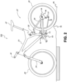
- Figure 1 illustrates bicycle 100 having a frame 24 with a suspension system comprising a swing arm portion 26 that, in use, is able to move relative to the rest of frame 24; this movement is permitted by, inter alia, a rear shock absorber and/or damping assembly 38.
- the front forks 34 also provide a suspension function via a damping assembly in at least one fork leg; as such the bicycle 100 is a full suspension bicycle (such as an ATB or mountain bike), although the embodiments described herein are not limited to use on full suspension bicycles.
- the term "suspension system” is intended to include vehicles having front suspension or rear suspension only, or both.
- swing arm portion 26 is pivotally attached to the main frame 24 at pivot point 12 which is located above the bottom bracket axis 11.
- Bicycle 100 includes a front wheel 28 which is coupled to the main frame 24 via front fork 34 and a rear wheel 30 which is coupled to the main frame 24 via swing arm portion 26.
- a seat 32 is connected to the main frame 24 in order to support a rider of the bicycle 20.
- the front wheel 28 is supported by a front fork 34 which, in turn, is secured to the main frame 24 by a handlebar assembly 36.
- the rear wheel 30 is connected to the swing arm portion 26 of the frame 22 at rear axle 15.
- a shock absorber e.g., damper assembly 38
- damper assembly 38 is positioned between the swing arm portion 26 and the frame 22 to provide resistance to the pivoting motion of the swing arm portion 26 about pivot point 12.
- the illustrated bicycle 100 includes a suspension member between swing arm portion 26 and the frame 24 which operate to substantially reduce rear wheel 30 impact forces from being transmitted to the rider of the bicycle 100.
- Bicycle 100 is driven by a chain 19 that is coupled with both front sprocket assembly 13 and rear sprocket 18.
- a force is applied to chain 19 which transfers the energy to rear sprocket 18.
- Optional chain tension device provides a variable amount of tension on chain 19.
- the need for chain 19 length variation can be due to a number of different gears that may be on one or both of front sprocket assembly 13 and/or rear sprocket 18 and/or changes in chain stay length as the distance between bottom bracket axis 11 (where front sprocket assembly 13 attaches to bicycle frame 24) and the rear axle 15 changes due to suspension articulation as shown in further detail in herein.
- FIG. 2 illustrates bicycle 100 having a suspended rear swing arm portion 26 as it traverses across terrain 45 and encounters a terrain feature 55 shown in accordance with an embodiment.
- Terrain feature 55 may be a dip, rock, bump, sidewalk, hole, or any other type of feature that will cause an articulation in the rear suspension of bicycle 100.
- terrain feature 55 will exert a force on rear wheel 30 of the bicycle 100.
- the angle of the resolved force relative to the rear wheel 30 is typically normal (substantially) to the rear wheel 30 at the point of impact. That force then imparts a component of the impact from terrain feature 55 to the axle 15 as dictated by the trajectory of the swing arm pivot point 12.
- rear suspension Although one type of rear suspension is shown herein it is for purposes of clarity. It should be appreciated that there may be many different ways of setting up a rear suspension. However, the following discussion is applicable to any rear suspension setup that has a swing arm pivot point 12 that is not located exactly at bottom bracket axis 11. That is, since the swing arm pivot point 12 is offset from the bottom bracket axis 11 (above, below, ahead, or behind) then when rear swing arm portion 26 rotates the chain stay length changes.
- Figure 3A is a side view 300 of the suspended rear swing arm portion 26 of the bicycle as it traverses across flat terrain 45 shown in accordance with an embodiment.
- Figure 3B is a side view 350 of the suspended rear swing arm portion 26 of the bicycle as it traverses across a terrain feature 55 causing a suspension event that modifies the chain stay length shown in accordance with an embodiment.
- the main pivot point 12 for bicycle 100 is slightly behind and higher than the bottom bracket axis 11. However, it could also include a couple of linkages and a number of different articulations. As such, 10 inches of rear travel 305 is not uncommon in a rear suspension bike. However, since the rear can travel throughout the 10-inch range, the chain stay length will change. For example, from the shortest distance when the bike is sitting to a longer distance when there is weight on the suspension, e.g., a rider on the bike, when bumps are hit, when pedal bob occurs, etc.
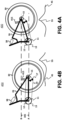
- Figure 4A is a side view 400 of the suspended rear swing arm portion 26 of the bicycle as it traverses across a terrain feature 55 having a suspension event that modifies the chain stay length shown in accordance with an embodiment.
- Figure 4B is a side view of the suspended rear swing arm portion of the bicycle as it returns to flat terrain 45 after the terrain feature 55 suspension event shown in accordance with an embodiment.
- the rear derailleur assembly 17, using one or more spring provides tension in the chain 19 for gear changing and suspension change events.
- a large suspension change event such as after contacting terrain feature 55 (e.g., hitting a bump causing a quick suspension articulation change)
- the spring pressure within the rear derailleur is not always able to keep up with the change in chain stay length.
- the quick change in chain stay length as the suspension travels back from B to A over rear travel 305 will result in a relaxing in the pressure on the chain 19 which will travel along chain 19 to the front sprocket assembly 13 and cause the chain 19 to disengage from the front sprocket assembly 13.
- One solution utilizes a friction clutch in the rear derailleur assembly 17 to reduce the release in chain pressure, thereby stopping chain 19 from getting enough slack to disengage from the front sprocket assembly 13.
- the use of the clutch restricts chain stay length growth. For example, as shown in Figures 3A and 3B when bicycle 100 encounters terrain feature 55 and initially distance of rear travel 305 from A to B, the necessary amount of chain will have to increase as the chain stay length increases to keep up with the suspension articulation.
- Figures 4A and 4B also include a sensor 415, such as an accelerometer, an optical detection (e.g., infrared motion sensor), an image capturing device (e.g., optical flow), a combination thereof, or the like.
- sensor 415 detects the amount of rotation and speed of rotation of the rear axle. In another embodiment, sensor 415 can determine the angle of swing arm portion 26.
- the swing arm portion 26 tilted in a manner that would suggest the bicycle 100 is going down a small incline (5-15 degrees), down a medium incline (16-30 degrees), down a large incline (31-90 degrees), traversing a flat section, going up a small incline (5-15 degrees), going up a medium incline (16-30 degrees), going up a large incline (31-90 degrees), etc.
- a number of degrees are provided to indicate three different levels of slope, it should be appreciated that there may be more of fewer different breakdowns of slope measurement. For example, in the simplest case it could be whether it is a downward slope (descending) or an inclined slope (ascending). In a more complicated example, there could be different levels for every 5 degrees, 7 degrees, 10 degrees, 15 degrees, or the like).
- sensor 415 could determine whether or not the chain is being rotated based on whether the pedals are moving or are stationary, etc.
- Sensor 415 may be positioned proximate a rear axle 15 of the bicycle 100 for sensing changes in terrain. As shown in Figures 4A and 4B , sensor 415 is mounted on swing arm portion 26 proximate the rear axle 15 of the bicycle. In one embodiment the angular orientation of a sensor 415 sensing axis is movable through a range or angle thereby allowing alteration of a force component sensed by sensor 415 in relation to a force (vector) input into the rear swing arm portion 26. It is understood that sensor 415 may be moved or mounted in any suitable configuration and allowing for any suitable range of adjustment as may be desirable. It is understood that the sensor may include one, two, three or more sensing axis'.
- sensor 415 may be coupled to the rear suspension, such as shock absorber and/or damper assembly 38, for measuring the operational characteristics of the rear suspension.
- Sensor 415 can be any suitable force or acceleration transducer (e.g. strain gage, Wheatstone bridge, accelerometer, hydraulic cylinder, interferometer based, optical, thermal, and acoustic or any suitable combination thereof). Sensor 415 may utilize solid state electronics, electro-mechanical principles, or any other suitable mechanisms.
- sensor 415 is a single axis self-powered accelerometer, such as for example ENDEVCO Model 2229C.
- the 2229C is a comparatively small device with overall dimensions of about 15 mm height by 10 mm diameter, and weighs about 4.9 g. Its power is self-generated and therefore the total power requirements for the bicycle 100 are reduced; this is an important advantage, at least for some types of bicycle, where overall weight is a concern.
- the single axis accelerometer comprises the ENDEVCO 12M1A, which is of the surface-mount type.
- the 12M1A is a single axis accelerometer comprising a bimorph sending element which operates in the bender mode. This accelerometer is particularly small and light, measuring about 4.5 mm by 3.8 mm by 0.85 mm, and weighs about 0.12 g.
- sensor 415 is a tri-axial accelerometer such as the ENDEVCO 67-100. This device has overall dimensions of about 23 mm length and 15 mm width, and weighs about 14 g. Other sensors known in the art may be used with the embodiments described herein.
- sensor 415 is attached to swing arm portion 26 directly, to any link thereof, to an intermediate mounting member or to any other portion or portions of the bicycle as may be useful for purposes disclosed herein.
- sensor 415 is fixed to an unsprung portion of the bicycle 100, such as for example swing arm portion 26, and another sensor 415 (such as an accelerometer as described above) is fixed to a sprung portion of the bicycle, such as for example the frame 24 of Figure 1 or 2 .
- Data from each sensor can, by a processor, be overlaid on a common time datum and suspension damping and/or spring effectiveness can be evaluated by comparing the data from the sensors on either "side" of the suspension unit.
- Sensors may be integrated with the vehicle structure and data processing system as described in U.S.
- Sensors and valve actuators e.g. electric solenoid or linear motor typenote that a rotary motor may also be used with a rotary actuated valve
- Sensors and valve actuators may be integrated herein utilizing principles outlined in SP-861-Vehicle Dynamics and Electronic Controlled Suspensions SAE Technical Paper Series no. 910661 by Shiozaki et al. for the International Congress and Exposition, Detroit, Michigan, February 25 - March 1, 1991 .
- sensor 415 puts out a voltage change corresponding to an input force.
- the outputs from one or more sensor 415 are reconciled in a controller or processor, such as a microprocessor, having an algorithm for weighting their respective inputs and generating a resulting singular command or signal based on a predetermined logic.
- sensor 415 senses an input force along the prescribed range or axis.
- a terrain feature 55 e.g., bump
- the angle of the resolved force from terrain feature 55 relative to the rear wheel 30 is typically normal (substantially) to the rear wheel 30 at the point of impact.
- That force then imparts a component of the impact of terrain feature 55 to the axle 15 as dictated by the trajectory of the swing arm portion 26.
- That component can be sensed by sensor 415 at a magnitude corresponding to the orientation of the sensor range or angle.
- the sensor axis orientation can be adjusted to make sensor 415 more or less sensitive to bumps and dips in the terrain.
- disengageable derailleur assembly 17 has a linkage mechanism attempting to position the rear derailleur to the left from the perspective of a rider on bicycle 100.
- Disengageable derailleur assembly 17 includes a frame attachment portion 505, a P-Knuckle assembly 510, a cage assembly 565 (which includes inner and outer cage plates 563, lower idler pully 520, and upper idler pully 520a.
- frame attachment portion 505 is coupled with swing arm portion 26.
- frame attachment portion 505 is part of the P-Knuckle assembly 510.
- Lower idle pully 520 (and similarly upper idle pully 520a) includes a cog having a plurality of teeth on an outer perimeter thereof, the cog provides continuous rotating contact with chain 19 of bicycle 100.
- lower idle pully 520 is horizontally adjustable across a number of rear sprocket 18 coupled with rear wheel 30 of bicycle 100.
- disengageable derailleur assembly 17 has an upper idle pully 520a proximal to the joint where P-Knuckle assembly 510 is located.
- Figure 6 is an exploded view of disengageable derailleur assembly 17 shown in accordance with an embodiment.
- disengageable derailleur assembly 17 includes P-Knuckle assembly 510 and cage assembly 565.
- P-Knuckle assembly 510 includes a P-Knuckle housing 615, a motor and gear 610, a spring (or solenoid) housing 620, a linear solenoid 625, a torsional power spring 630, a P-Knuckle clutch plate 635 (with gear), at least one thrust bearing 640, and a P-Knuckle cover 644.
- cage assembly 565 includes a cage bearing 645, a cage plate 650, at least one snap ring 655, inner and outer cage plates 563, lower idler pully 520, and upper idler pully 520a.
- cage plate 650 will decouple the cage assembly 565 from the P-Knuckle assembly 510 though the axial movement of the P-Knuckle clutch plate 635.
- the cage assembly 565 would move relative to the bicycle frame, while the P-Knuckle assembly 510 would be disengaged during a chain growth or reduction event.
- disengageable derailleur assembly 17 can have more or fewer components.
- a number of the components shown could be combined to a single component or could be broken from one into a plurality of components.
- disengageable derailleur assembly 17 could include more of fewer of the components shown.
- the use of the designated separate components defined as being part of P-Knuckle assembly 510 and cage assembly 565 in the discussion is provided as one embodiment, and is shown merely for purposes of clarity. It should be appreciated that in one embodiment, one or more of the components could be moved into the opposite assembly.
- FIG. 7 a cutaway view A-A of P-Knuckle assembly 510 of the disengageable derailleur assembly 17 which includes a portion of cage assembly 565 is shown in accordance with an embodiment.
- the operation of the P-Knuckle assembly 510 as seen in the sectional view A-A is shown in two different orientations in Figures 8 and 9 and is described in the discussion thereof.
- FIG. 8 a side sectional view A-A of the P-Knuckle assembly 510 of the disengageable derailleur assembly 17 which also includes a portion of cage assembly 565 is shown in accordance with an embodiment.
- a cage free configuration is shown in accordance with an embodiment.
- the cage free configuration shows a left force 805, a gear interface 810, motor and gear 610, a clearance 825, a frictional interface 830, a locking 806 of linear solenoid 625, a locking 816 of motor and gear 610, a cage rotation axis 820, and mechanical connections 840.
- cage assembly 565 rotates freely about the axis indicated by cage plate rotation 820.
- one embodiment will frictionally decouple the cage assembly 565 from the P-Knuckle assembly 510 though the axial movement of the P-Knuckle clutch plate 635 via torsional power spring 630.
- a controller that is, in one embodiment, part of linear solenoid 625) senses and stores position of P-Knuckle assembly 510 with respect to cage assembly 565 at disengagement to ensure a proper orientation during a later re-engagement.
- FIG. 9 a side sectional view A-A of the P-Knuckle assembly 510 of the disengageable derailleur assembly 17 which also includes a portion of cage assembly 565 is shown in accordance with an embodiment.
- a cage sprung configuration is shown in accordance with an embodiment.
- the cage sprung configuration shows a right force 905, gear interface 810, motor and gear 610, clearance 825, frictional interface 830, the unlocking 916 of motor and gear 610, free cage rotation 820, and mechanical connections 840.
- cage assembly 565 rotates about the axis indicated by cage rotation 820 under a spring force.
- one embodiment will frictionally couple the cage assembly 565 to the P-Knuckle assembly 510 using torsional power spring 630 through movement of P-Knuckle clutch plate 635.
- motor and gear 610 engages to restore timing of cage assembly 565 and torsional power spring 630 using clutch plate 635.
- the friction interface 830 and clearance 825 are switched.
- disengageable derailleur assembly 17 in order to compensate for the engagement and disengagement, disengageable derailleur assembly 17 will lock torsional power spring 630 to itself once cage assembly 565 is frictionally disengaged from P-Knuckle assembly 510 to keep the appropriate preload.
- the appropriate preload maintenance is implemented through linear solenoid 625 and opposing frictional clutch-type (in a traditional, auto-sense) clutch plate 635.
- the maintenance of the orientation of cage assembly 565 with the appropriate force on torsional power spring 630 is maintained by simultaneously disengaging torsional power spring 630 from cage assembly 565 and engaging torsional power spring 630 with something else in P-Knuckle assembly 510 such as P-Knuckle 615 housing (or the like) to keep the proper preload on torsional power spring 630 and vice versa for the reengagement of cage assembly 565 with P-Knuckle assembly 510.
- the bicycle is approaching a series of logs and the rear suspension is going to be working.
- cage assembly 565 frictionally disengages from P-Knuckle assembly 510 and the rear suspension is compressed to 25 degrees.
- the rider begins to pedal which causes cage assembly 565 to frictionally reengage with P-Knuckle assembly 510 at 15 degrees. If this continued for each log, and without any type of error correction, at some point torsional power spring 630 would be either packed or unpacked.
- the frictional reengaging of torsional power spring 630 with cage assembly 565 will occur before the disengagement of P-Knuckle 615 housing with torsional power spring 630. In so doing, there is no time during the engagement/disengagement/reengagement process that torsional power spring 630 and cage assembly 565 are not maintaining their correct orientation. Thus, the risk of torsional power spring 630 winding all the way up or down due to an improper engagement disengagement /reengagement is removed. Moreover, this process removes the opportunity for the torsion power spring 630 to be packed or unwound due to several uncoordinated engagement /disengagement /reengagement occurrences.
- the senor 415 is used to track the orientation of the suspension and the tracking information is provided to a controller for motor and gear 610 which will allow P-Knuckle assembly 510 to establish the proper timing on torsional power spring 630 prior to the frictional re-engagement of P-Knuckle assembly 510 with cage assembly 565.
- wave dynamics of the chain itself can be used to manage the frictional disengagement and reengagement.
- disengageable derailleur assembly 17 can actively, automatically, and continually adjust the position of P-Knuckle assembly 510 with respect to the position of cage assembly 565 based on suspension position and gearing such that the system will always have the correct amount of chain paid out. This would minimize chain slap and could eliminate load on the whole suspension system.
- this is realized by using a stepper motor & controller (e.g., motor and gear 610) which receives input from both from a gear selection and a suspension position (e.g., information from sensor 415) to give the disengageable derailleur assembly 17 some tolerance if sampling rates of the system could not create an effective "continuous" signal.
- cage assembly 565 and P-Knuckle assembly 510 would be frictionally disengaged for compressions/chain growth and reengaged for rebound/chain shrink.
- disengageable derailleur assembly 17 remains engaged under normal chain stay length changes such as suspension articulation due to pedaling, normal suspension travel issues, and the like.
- P-Knuckle assembly 510 will not provide significant damping during the chain length extension (as would occur when the suspension travels as shown from Figure 3A to Figure 3B ).
- the suspension returns e.g., travels from Figure 4A to Figure 4B
- P-Knuckle assembly 510 will increase the resistance to chain 19, thereby stopping chain 19 from obtaining enough slack to disengage from front sprocket assembly 13 or rear sprocket 18.
- the damping force is automatically controlled by a controller in response to the input from sensor 415 when the bicycle 100 is in use.
- the user may be able to override and/or adjust this automatic control using a manual input.
- a controller e.g. a memory and a processor/microprocessor, or an ASIC.
- P-Knuckle assembly 510 is responsive to signals and power transmitted from the controller or processor. As the values increase or decrease, an electromagnetic circuit is used to engage or disengage the cage assembly 565 and P-Knuckle assembly 510 which reduces the influence that the engaged P-Knuckle assembly 510 will have on the suspension articulation.
- sensor 415 P-Knuckle assembly 510, and the like are interconnected or connected by wire, wireless, WAN, LAN, Bluetooth, Wi-Fi, ANT (i.e. GARMIN low power usage protocol), or any suitable power or signal transmitting mechanism.
- disengageable derailleur assembly 17 can have more of fewer components.
- a number of the components shown could be combined to a single component or could be broken from one into a plurality of components.
- disengageable derailleur assembly 17 could include more of fewer of the components shown.
- the use of the designated separate components in the discussion is provided as one embodiment, of many possible and is shown merely for purposes of clarity.
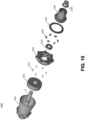
- electronic automatically decoupling hub assembly 1000 includes an axle 15, a hub shell non drive side (NDS) 1005, a controller 1010, one or more inductors/electromagnets 1015, a rachet ring 1020 (e.g., a hub shell drive side (DS)), a bearing 1025, one or more pawls 1030 (whose number, in one embodiment, may be analogous to the number of inductor/electromagnets 1015) , a seal 1035, a cassette body assembly 1040, and an end cap 1045.
- NDS hub shell non drive side
- DS hub shell drive side
- electronic automatically decoupling hub assembly 1000 uses magnets in each of the pawls 1030 with an inductors/electromagnets 1015 above it and controlled by a controller 1010 inside the hub shell NDS 1005.
- a controller 1010 inside the hub shell NDS 1005.
- the pawls 1030 When not pedaling the pawls 1030 would be disengaged by the inductors/electromagnets 1015 turning on or flipping polarity to attract the pawls 1030 upwards away from the rachet ring 1020 on the cassette body.
- pedaling the inductors/electromagnets 1015 would be turned off and the magnets of pawls 1030 attracted to the ferrous rachet ring 1020 (less energy usage).
- the polarity of the inductors/electromagnets 1015 could be flipped to repel the pawls 1030 away, forcing them toward the rachet ring 1020.
- Hub shell NDS 1005 is the left side of the hub.
- Controller 1010 provides power/or polarity to the inductor/ electromagnets and could house a battery, dynamo, or generator to provide a charge to a battery or create its own power. Further operation of controller 1010 is provided below.
- One or more inductors/electromagnets 1015 which receive input from controller 1010 to engage/disengage the pawls 1030 with respect to the ratchet ring 1020.
- Rachet ring 1020 provides a number of teeth to receive the pawls 1030. In general, bigger teeth and pawls will deal better with larger amounts of torque, while a finer set up provides faster engagement.
- Bearing 1025 is used to maintain rachet ring 1020 about the axle 15.
- One or more pawls 1030 are used to engage with the teeth of ratchet ring 1020. Although 6 pawls 1030 are shown that number is exemplary. To produce a faster pick-up in one embodiment, the pawls 1030 are offset to double the number of engagements per revolution.
- Seal 1035 is used to keep dirt out while also keeping pawls 1030 from falling out or being lost when the hub is disassembled.
- Cassette body assembly 1040 is used to hold the cassette cogs.
- the cassette body assembly 1040 includes splines thereon to mechanically couple with the cassette cogs.
- End cap 1045 is used to prevent dust and water from entering into electronic automatically decoupling hub assembly 1000.
- controller 1010 provides a polarity to inductors/electromagnets 1015 that push or pull pawls 1030 into an engaged position, or they are spring loaded to provide inductors/electromagnets 1015 to engage/disengage the pawls 1030.
- the rachet ring 1020 is a ferrous material that attracts the (magnetic) pawls 1030 to the rachet ring 1020, while the electromagnetic controller 1010 on the other side will provide an electromagnetic force via inductors/electromagnets 1015 that can be used to attract the magnetic pawls 1030.
- the electromagnetic force could be used to engage the pawls 1030 with ratchet ring 1020 when pawls 1030 are retracted when in a resting state. In another embodiment, the electromagnetic force could be used to disengage the pawls 1030 from ratchet ring 1020 when pawls 1030 are deployed when in a resting state.
- electronic automatically decoupling hub assembly 1000 is mechanical and the pawls 1030 are engaged or disengaged electronic automatically through a serious of stepper motors, a single stepper motor with a series of linkages to drive each of the pawls 1030 simultaneously.
- the engagement/disengagement of the pawls 1030 could be solenoid induced, etc.
- pawls 1030 can be engaged and/or disengaged electronic automatically based on input from sensor 415.
- the sensor 415 output can be used by a processor in electronic automatically decoupling hub assembly 1000.
- the activation can be at a number of different levels and as such, the electronic automatically decoupling hub assembly 1000 could have a nearly infinite amount of automatic engagement and disengagement, in real-time, and throughout the ride. As such, the rider would have all of the normal suspension articulation during most of the ride and when different levels of violent suspension articulation events occurred, the chain pressure via the electronic automatically decoupling hub assembly 1000 would be reduced to ensure full suspension articulation while also minimizing the opportunity for a violent feedback through the pedals that would be transferred to the rider.
- the damping force is electronic automatically controlled by controller 1010 in response to the input from sensor 415 when the bicycle 100 is in use.
- the user may be able to override and/or adjust this automatic control using a manual input.
- controller 1010 e.g. a memory and a processor/microprocessor, or an ASIC.
- electronic automatically decoupling hub assembly 1000 engages or disengages pawls 1030 with rachet ring 1020 responsive to signals and power transmitted from the controller 1010.
- controller 1010 compares the output voltage of sensor 415 to a plurality of preset values. As the values increase, an electromagnetic circuit is used to engages or disengages pawls 1030 with rachet ring 1020.
- the electromagnetic circuit when the output voltage of sensor 415 falls below a preset value, the electromagnetic circuit is used to engage or disengage pawls 1030 with respect to rachet ring 1020.
- some or all of components including sensor 415, controller 1010, and the like are interconnected or connected by wire, wireless, WAN, LAN, Bluetooth, Wi-Fi, ANT (i.e. GARMIN low power usage protocol), or any suitable power or signal transmitting mechanism.
- electronic automatically decoupling hub assembly 1000 can have more of fewer components.
- a number of the components shown could be combined to a single component or could be broken from one into a plurality of components.
- electronic automatically decoupling hub assembly 1000 could include more of fewer of the components shown.
- the use of the designated separate components in the discussion is provided as one embodiment, of many possible and is shown merely for purposes of clarity.
- FIG. 11 a partially exploded view of an electronic automatically decoupling hub assembly 1000 is shown in accordance with an embodiment.
- electronic automatically decoupling hub assembly 1000 of Figure 11 shows axle 15, hub shell NDS 1005, controller 1010, one or more inductors/electromagnets 1015, and rachet ring 1020 and bearing 1025 in proper orientation and build.
- Figure 11 shows the exploded view of the one or more pawls 1030, seal 1035, cassette body assembly 1040, and end cap 1045.
- the section view of electronic automatically decoupling hub assembly 1000 of Figure 12 shows all of the components of electronic automatically decoupling hub assembly 1000 in an as build orientation.
- the as built orientation shows axle 15, hub shell NDS 1005, controller 1010, one or more inductors/electromagnets 1015, rachet ring 1020, bearing 1025, one or more pawls 1030, seal 1035, cassette body assembly 1040, and end cap 1045.
- electronic automatically decoupling hub assembly 1000 of Figure 13 includes an axle 15, one or more inductors/electromagnets 1015, rachet ring 1020, bearing 1025, one or more pawls 1030.
- An electronic automatically decoupling hub assembly for a vehicle having a rear suspension assembly that can articulate during use, the articulation causing a distance between a center chain sprocket and a rear wheel sprocket of the vehicle to change causing changes in chain tightness
- the electronic automatically decoupling hub assembly adapted to be mounted on the rear wheel and to be driven by the rear wheel sprocket
- the electronic automatically decoupling hub assembly comprising: an axle; a hub shell rotationally positioned about the axle, the hub shell housing: a bearing rotationally positioned about the axle; a rachet ring rotationally positioned about the bearing, the ratchet ring having at least one tooth therein; an inductor comprising at least one pawl to selectively engage or disengage with the at least one tooth of the ratchet ring, a selective disengagement of the at least one pawl from the at least one tooth of the ratchet ring will cause the electronic automatically decoupling hub assembly to enter a freewheel state, and a
- the electronic automatically decoupling hub assembly as stated above, wherein the hub shell is rotationally positioned about the axle on a non-drive side of a wheel, and the bearing is rotationally positioned about the axle on a drive side of the wheel.
- the electronic automatically decoupling hub assembly as stated above wherein: the controller is adapted to provide at least one automatic activation signal; and the inductor is adapted to receive the at least one automatic activation signal and engage the at least one pawl with the at least one tooth of the ratchet ring.
- the electronic automatically decoupling hub assembly as stated above, wherein: the controller is adapted to provide at least one automatic deactivation signal; and the inductor is adapted to receive the at least one automatic deactivation signal and disengage the at least one pawl from the at least one tooth of the ratchet ring.
- the electronic automatically decoupling hub assembly as stated above, further comprising: the controller adapted to provide a plurality of automatic activation signals; the controller adapted to provide a plurality of automatic deactivation signals; and the inductor adapted to receive the plurality of automatic activation signals and the plurality of automatic deactivation signals and engage or disengage the at least one pawl with the at least one tooth of the ratchet ring in accordance therewith.
- the electronic automatically decoupling hub assembly as stated above, further comprising: said sensor to provide an input to the controller, the input causing the controller to automatically provide the at least one automatic signal to the inductor.
- the electronic automatically decoupling hub assembly as stated above, where the sensor is an accelerometer, an optical detection device, or an image capturing device.
- the electronic automatically decoupling hub assembly as stated above, wherein: the ratchet ring comprises a plurality of teeth therein; and the inductor comprises a plurality of pawls, the plurality of pawls adapted to selectively engage or disengage with at least two of the plurality of teeth of the ratchet ring.
- the electronic automatically decoupling hub assembly as stated above, further comprising: a seal to contain the at least one pawl within the electronic automatically decoupling hub assembly; a cassette body assembly coupled with the rachet ring; and an end cap coupled with the cassette body assembly to prevent a contaminant entry into the electronic automatically decoupling hub assembly.
- said inductor comprises an electromagnet adapted so that in a normal state, the at least one pawl is selectively engaged with the at least one tooth of the ratchet ring such that the electronic automatically decoupling hub assembly is in said force transfer state; and said controller is adapted to provide at least one automatic deactivation signal to the electromagnet, the at least one automatic deactivation signal causing the electromagnet to disengage the at least one pawl from the at least one tooth of the ratchet ring such that the electronic automatically decoupling hub assembly enters into a freewheel state.
Landscapes
- Engineering & Computer Science (AREA)
- General Engineering & Computer Science (AREA)
- Mechanical Engineering (AREA)
- Physics & Mathematics (AREA)
- Electromagnetism (AREA)
- Fluid Mechanics (AREA)
- Axle Suspensions And Sidecars For Cycles (AREA)
Applications Claiming Priority (5)
| Application Number | Priority Date | Filing Date | Title |
|---|---|---|---|
| US201862771416P | 2018-11-26 | 2018-11-26 | |
| US201862772504P | 2018-11-28 | 2018-11-28 | |
| US201962805885P | 2019-02-14 | 2019-02-14 | |
| US16/694,732 US11428279B2 (en) | 2018-11-26 | 2019-11-25 | Suspension enhancing hub and rear derailleur assembly |
| EP19211677.0A EP3657037B1 (fr) | 2018-11-26 | 2019-11-26 | Ensemble moyeu et dérailleur arrière améliorant la suspension |
Related Parent Applications (1)
| Application Number | Title | Priority Date | Filing Date |
|---|---|---|---|
| EP19211677.0A Division EP3657037B1 (fr) | 2018-11-26 | 2019-11-26 | Ensemble moyeu et dérailleur arrière améliorant la suspension |
Publications (1)
| Publication Number | Publication Date |
|---|---|
| EP4350162A1 true EP4350162A1 (fr) | 2024-04-10 |
Family
ID=68699240
Family Applications (3)
| Application Number | Title | Priority Date | Filing Date |
|---|---|---|---|
| EP23195797.8A Pending EP4350162A1 (fr) | 2018-11-26 | 2019-11-26 | Ensemble moyeu et dérailleur arrière améliorant la suspension |
| EP19211677.0A Active EP3657037B1 (fr) | 2018-11-26 | 2019-11-26 | Ensemble moyeu et dérailleur arrière améliorant la suspension |
| EP22172854.6A Pending EP4075006A1 (fr) | 2018-11-26 | 2019-11-26 | Moyeu améliorant la suspension et ensemble dérailleur arrière |
Family Applications After (2)
| Application Number | Title | Priority Date | Filing Date |
|---|---|---|---|
| EP19211677.0A Active EP3657037B1 (fr) | 2018-11-26 | 2019-11-26 | Ensemble moyeu et dérailleur arrière améliorant la suspension |
| EP22172854.6A Pending EP4075006A1 (fr) | 2018-11-26 | 2019-11-26 | Moyeu améliorant la suspension et ensemble dérailleur arrière |
Country Status (2)
| Country | Link |
|---|---|
| US (2) | US11428279B2 (fr) |
| EP (3) | EP4350162A1 (fr) |
Families Citing this family (9)
| Publication number | Priority date | Publication date | Assignee | Title |
|---|---|---|---|---|
| TWI664113B (zh) * | 2018-04-25 | 2019-07-01 | Tektro Technology Corporation | 自行車撥鏈器 |
| US11530015B2 (en) | 2019-02-15 | 2022-12-20 | Sram, Llc | Bicycle control system |
| TWI729556B (zh) * | 2019-11-06 | 2021-06-01 | 天心工業股份有限公司 | 自行車之後變速器 |
| TWI712547B (zh) * | 2019-11-06 | 2020-12-11 | 天心工業股份有限公司 | 自行車之後變速器 |
| USD1017477S1 (en) * | 2021-02-23 | 2024-03-12 | Marcin GOLEC | Chain-guide for cycle gear |
| US11713095B2 (en) * | 2021-05-07 | 2023-08-01 | Sram, Llc | Bicycle derailleur |
| IT202100024737A1 (it) * | 2021-09-28 | 2023-03-28 | Campagnolo Srl | Deragliatore elettrico/elettronico di bicicletta a parallelogramma articolato |
| USD1009722S1 (en) * | 2021-11-10 | 2024-01-02 | The Cycle Group | One-piece chain cage for a rear derailleur |
| US11814138B1 (en) * | 2022-06-28 | 2023-11-14 | Ad-Ii Engineering Inc. | Rear derailleur |
Citations (11)
| Publication number | Priority date | Publication date | Assignee | Title |
|---|---|---|---|---|
| US4773671A (en) | 1986-02-21 | 1988-09-27 | Honda Giken Kogyo Kabushiki Kaisha | Method of controlling damping force of damper |
| US4984819A (en) | 1988-04-14 | 1991-01-15 | Atsugi Motor Parts Company, Limited | Automotive suspension system and shock absorber therefor |
| US5027303A (en) | 1989-07-17 | 1991-06-25 | Witte Don C | Measuring apparatus for pedal-crank assembly |
| US5105918A (en) | 1989-10-23 | 1992-04-21 | Nippondenso Co., Ltd. | Detection of damping force for shock absorber control |
| US5390949A (en) | 1993-03-08 | 1995-02-21 | The University Of Toledo | Active suspension systems and components using piezoelectric sensing and actuation devices |
| US6244398B1 (en) | 1997-05-15 | 2001-06-12 | K2 Bike Inc. | Shock absorber with variable bypass damping |
| US6427812B2 (en) | 1997-07-08 | 2002-08-06 | Active Control Experts, Inc. | Damper and valve |
| US20030132600A1 (en) * | 2000-01-13 | 2003-07-17 | Shimano Inc. | Bicycle suspension |
| US6935157B2 (en) | 2002-10-11 | 2005-08-30 | Larry D. Miller | Anti-bob system for cycles |
| WO2015013802A1 (fr) * | 2013-07-29 | 2015-02-05 | Magna Powertrain Inc. | Embrayage à roue libre sélectionnable muni d'une entretoise à induit séparé |
| WO2018144185A1 (fr) * | 2017-02-02 | 2018-08-09 | Means Industries, Inc. | Ensembles de commande et d'accouplement à roue libre sans frottement et dispositif actionneur linéaire commutable et appareil électromécanique à mouvement alternatif à utiliser dans ceux-ci |
Family Cites Families (16)
| Publication number | Priority date | Publication date | Assignee | Title |
|---|---|---|---|---|
| DE4340471C1 (de) * | 1993-11-27 | 1995-02-02 | Fichtel & Sachs Ag | Kettenschaltung für Fahrräder |
| US6065580A (en) | 1998-08-24 | 2000-05-23 | Kirk; Friedrich | Heavy duty freewheel hub for bicycles |
| US8312976B2 (en) | 2008-04-03 | 2012-11-20 | Bear Corporation | High efficiency bicycle hub |
| TWM348027U (en) * | 2008-08-25 | 2009-01-01 | Kun Teng Industry Co Ltd | Left/right driving exchangeable external fixed pawl-type ratchet hub |
| CN102753429B (zh) * | 2010-01-22 | 2015-11-25 | 福斯特资产有限公司 | 具有整合式转矩传感器的马达 |
| DE202010016798U1 (de) | 2010-12-18 | 2012-03-19 | Canyon Bicycles Gmbh | Fahrradnabengetriebe |
| US9255614B2 (en) * | 2010-12-10 | 2016-02-09 | Means Industries, Inc. | Electronic vehicular transmission and coupling and control assembly for use therein |
| DE102011051850B3 (de) | 2011-07-14 | 2012-12-06 | Karsten Bettin | Hinterradantrieb, wahlweise für Fahrräder mit kleinen Laufrädern oder für Anhängefahrräder |
| US9475547B2 (en) * | 2012-02-06 | 2016-10-25 | Brian Jordan | Derailleur with damping assembly |
| FR3012108A1 (fr) | 2013-10-18 | 2015-04-24 | Max Daniel Lauret | Combine sur axe stator de transmission et de suspension pour velo electrique |
| US9541143B2 (en) * | 2014-01-08 | 2017-01-10 | Means Industries, Inc. | Magnetic system for controlling an operating mode of an overrunning coupling assembly and overrunning coupling and magnetic control assembly including the system |
| WO2016057640A2 (fr) * | 2014-10-07 | 2016-04-14 | Magna Powertrain Of America, Inc. | Appareil d'embrayage électro-mécanique |
| DE202015005747U1 (de) | 2015-08-18 | 2016-11-21 | Canyon Bicycles Gmbh | Hinterradnabe sowie Fahrradachse |
| US10562387B2 (en) * | 2016-07-25 | 2020-02-18 | Magna Powertrain Inc. | Coil module assembly with thermally decoupled solenoid and circuit |
| TWI670186B (zh) * | 2018-01-31 | 2019-09-01 | 大陸商明倫運動器材(淮安)有限公司 | 可轉換左右驅的輪轂驅動裝置 |
| US11022186B2 (en) * | 2018-04-18 | 2021-06-01 | Magna Powertrain, Inc. | Selectable one-way coupling with debris containment |
-
2019
- 2019-11-25 US US16/694,732 patent/US11428279B2/en active Active
- 2019-11-26 EP EP23195797.8A patent/EP4350162A1/fr active Pending
- 2019-11-26 EP EP19211677.0A patent/EP3657037B1/fr active Active
- 2019-11-26 EP EP22172854.6A patent/EP4075006A1/fr active Pending
-
2022
- 2022-08-18 US US17/890,988 patent/US20220389979A1/en active Pending
Patent Citations (12)
| Publication number | Priority date | Publication date | Assignee | Title |
|---|---|---|---|---|
| US4773671A (en) | 1986-02-21 | 1988-09-27 | Honda Giken Kogyo Kabushiki Kaisha | Method of controlling damping force of damper |
| US4984819A (en) | 1988-04-14 | 1991-01-15 | Atsugi Motor Parts Company, Limited | Automotive suspension system and shock absorber therefor |
| US5027303A (en) | 1989-07-17 | 1991-06-25 | Witte Don C | Measuring apparatus for pedal-crank assembly |
| US5105918A (en) | 1989-10-23 | 1992-04-21 | Nippondenso Co., Ltd. | Detection of damping force for shock absorber control |
| US5390949A (en) | 1993-03-08 | 1995-02-21 | The University Of Toledo | Active suspension systems and components using piezoelectric sensing and actuation devices |
| US6244398B1 (en) | 1997-05-15 | 2001-06-12 | K2 Bike Inc. | Shock absorber with variable bypass damping |
| US6427812B2 (en) | 1997-07-08 | 2002-08-06 | Active Control Experts, Inc. | Damper and valve |
| US20030132600A1 (en) * | 2000-01-13 | 2003-07-17 | Shimano Inc. | Bicycle suspension |
| US6863291B2 (en) | 2000-01-13 | 2005-03-08 | Shimano, Inc. | Bicycle suspension |
| US6935157B2 (en) | 2002-10-11 | 2005-08-30 | Larry D. Miller | Anti-bob system for cycles |
| WO2015013802A1 (fr) * | 2013-07-29 | 2015-02-05 | Magna Powertrain Inc. | Embrayage à roue libre sélectionnable muni d'une entretoise à induit séparé |
| WO2018144185A1 (fr) * | 2017-02-02 | 2018-08-09 | Means Industries, Inc. | Ensembles de commande et d'accouplement à roue libre sans frottement et dispositif actionneur linéaire commutable et appareil électromécanique à mouvement alternatif à utiliser dans ceux-ci |
Non-Patent Citations (1)
| Title |
|---|
| SHIOZAKI ET AL., INTERNATIONAL CONGRESS AND EXPOSITION, DETROIT, MICHIGAN |
Also Published As
| Publication number | Publication date |
|---|---|
| US20220389979A1 (en) | 2022-12-08 |
| EP4075006A1 (fr) | 2022-10-19 |
| US20200166089A1 (en) | 2020-05-28 |
| EP3657037A1 (fr) | 2020-05-27 |
| EP3657037B1 (fr) | 2023-10-18 |
| US11428279B2 (en) | 2022-08-30 |
Similar Documents
| Publication | Publication Date | Title |
|---|---|---|
| US11428279B2 (en) | Suspension enhancing hub and rear derailleur assembly | |
| US6863291B2 (en) | Bicycle suspension | |
| EP1241087B1 (fr) | Suspension de bicyclette | |
| US10457348B2 (en) | Bicycle rear suspension | |
| US10351206B2 (en) | Vehicle terrain-tracking systems | |
| US7395892B2 (en) | Cycle suspension assembly | |
| EP1698549B1 (fr) | Bicyclette avec suspension arrière | |
| EP0399615B1 (fr) | Bicyclette | |
| US9845132B2 (en) | Mountain bicycle with rear suspension having neutral braking trajectory | |
| US9908583B2 (en) | Bicycle rear suspension with a two axis wheel path | |
| EP3717341A1 (fr) | Ensemble amortisseur de dérailleur arrière | |
| EP1234760A2 (fr) | Blocage automatique de suspension pour bicyclettes | |
| WO2005090149A1 (fr) | Ensemble suspension pour cycles | |
| AU2020295647A1 (en) | Vehicle |
Legal Events
| Date | Code | Title | Description |
|---|---|---|---|
| PUAI | Public reference made under article 153(3) epc to a published international application that has entered the european phase |
Free format text: ORIGINAL CODE: 0009012 |
|
| STAA | Information on the status of an ep patent application or granted ep patent |
Free format text: STATUS: THE APPLICATION HAS BEEN PUBLISHED |
|
| AC | Divisional application: reference to earlier application |
Ref document number: 3657037 Country of ref document: EP Kind code of ref document: P |
|
| AK | Designated contracting states |
Kind code of ref document: A1 Designated state(s): AL AT BE BG CH CY CZ DE DK EE ES FI FR GB GR HR HU IE IS IT LI LT LU LV MC MK MT NL NO PL PT RO RS SE SI SK SM TR |