EP4350146A1 - Screw compressor - Google Patents
Screw compressor Download PDFInfo
- Publication number
- EP4350146A1 EP4350146A1 EP22816023.0A EP22816023A EP4350146A1 EP 4350146 A1 EP4350146 A1 EP 4350146A1 EP 22816023 A EP22816023 A EP 22816023A EP 4350146 A1 EP4350146 A1 EP 4350146A1
- Authority
- EP
- European Patent Office
- Prior art keywords
- suction
- bearing
- space
- casing
- liquid supply
- Prior art date
- Legal status (The legal status is an assumption and is not a legal conclusion. Google has not performed a legal analysis and makes no representation as to the accuracy of the status listed.)
- Pending
Links
- 239000007788 liquid Substances 0.000 claims abstract description 197
- 230000001050 lubricating effect Effects 0.000 claims abstract description 82
- 238000007789 sealing Methods 0.000 claims abstract description 50
- 238000005192 partition Methods 0.000 claims abstract description 22
- 238000003756 stirring Methods 0.000 description 21
- 238000005096 rolling process Methods 0.000 description 13
- 239000010687 lubricating oil Substances 0.000 description 7
- 230000033001 locomotion Effects 0.000 description 5
- 239000003921 oil Substances 0.000 description 5
- 238000010586 diagram Methods 0.000 description 4
- 230000015556 catabolic process Effects 0.000 description 2
- 238000006731 degradation reaction Methods 0.000 description 2
- 230000007423 decrease Effects 0.000 description 1
- 230000000694 effects Effects 0.000 description 1
- 239000012530 fluid Substances 0.000 description 1
- 238000002347 injection Methods 0.000 description 1
- 239000007924 injection Substances 0.000 description 1
- 238000005461 lubrication Methods 0.000 description 1
- 238000000034 method Methods 0.000 description 1
- XLYOFNOQVPJJNP-UHFFFAOYSA-N water Substances O XLYOFNOQVPJJNP-UHFFFAOYSA-N 0.000 description 1
Images


Classifications
-
- F—MECHANICAL ENGINEERING; LIGHTING; HEATING; WEAPONS; BLASTING
- F04—POSITIVE - DISPLACEMENT MACHINES FOR LIQUIDS; PUMPS FOR LIQUIDS OR ELASTIC FLUIDS
- F04C—ROTARY-PISTON, OR OSCILLATING-PISTON, POSITIVE-DISPLACEMENT MACHINES FOR LIQUIDS; ROTARY-PISTON, OR OSCILLATING-PISTON, POSITIVE-DISPLACEMENT PUMPS
- F04C18/00—Rotary-piston pumps specially adapted for elastic fluids
- F04C18/08—Rotary-piston pumps specially adapted for elastic fluids of intermeshing-engagement type, i.e. with engagement of co-operating members similar to that of toothed gearing
- F04C18/12—Rotary-piston pumps specially adapted for elastic fluids of intermeshing-engagement type, i.e. with engagement of co-operating members similar to that of toothed gearing of other than internal-axis type
- F04C18/14—Rotary-piston pumps specially adapted for elastic fluids of intermeshing-engagement type, i.e. with engagement of co-operating members similar to that of toothed gearing of other than internal-axis type with toothed rotary pistons
- F04C18/16—Rotary-piston pumps specially adapted for elastic fluids of intermeshing-engagement type, i.e. with engagement of co-operating members similar to that of toothed gearing of other than internal-axis type with toothed rotary pistons with helical teeth, e.g. chevron-shaped, screw type
-
- F—MECHANICAL ENGINEERING; LIGHTING; HEATING; WEAPONS; BLASTING
- F04—POSITIVE - DISPLACEMENT MACHINES FOR LIQUIDS; PUMPS FOR LIQUIDS OR ELASTIC FLUIDS
- F04C—ROTARY-PISTON, OR OSCILLATING-PISTON, POSITIVE-DISPLACEMENT MACHINES FOR LIQUIDS; ROTARY-PISTON, OR OSCILLATING-PISTON, POSITIVE-DISPLACEMENT PUMPS
- F04C29/00—Component parts, details or accessories of pumps or pumping installations, not provided for in groups F04C18/00 - F04C28/00
- F04C29/02—Lubrication; Lubricant separation
- F04C29/028—Means for improving or restricting lubricant flow
-
- F—MECHANICAL ENGINEERING; LIGHTING; HEATING; WEAPONS; BLASTING
- F04—POSITIVE - DISPLACEMENT MACHINES FOR LIQUIDS; PUMPS FOR LIQUIDS OR ELASTIC FLUIDS
- F04C—ROTARY-PISTON, OR OSCILLATING-PISTON, POSITIVE-DISPLACEMENT MACHINES FOR LIQUIDS; ROTARY-PISTON, OR OSCILLATING-PISTON, POSITIVE-DISPLACEMENT PUMPS
- F04C2240/00—Components
- F04C2240/50—Bearings
- F04C2240/52—Bearings for assemblies with supports on both sides
-
- F—MECHANICAL ENGINEERING; LIGHTING; HEATING; WEAPONS; BLASTING
- F04—POSITIVE - DISPLACEMENT MACHINES FOR LIQUIDS; PUMPS FOR LIQUIDS OR ELASTIC FLUIDS
- F04C—ROTARY-PISTON, OR OSCILLATING-PISTON, POSITIVE-DISPLACEMENT MACHINES FOR LIQUIDS; ROTARY-PISTON, OR OSCILLATING-PISTON, POSITIVE-DISPLACEMENT PUMPS
- F04C27/00—Sealing arrangements in rotary-piston pumps specially adapted for elastic fluids
- F04C27/008—Sealing arrangements in rotary-piston pumps specially adapted for elastic fluids for other than working fluid, i.e. the sealing arrangements are not between working chambers of the machine
- F04C27/009—Shaft sealings specially adapted for pumps
Definitions
- the present invention relates to a screw compressor and is suited for application to a screw compressor including a liquid supplying mechanism.
- an oil-cooling-type screw compressor disclosed by PTL 1 as a screw compressor.
- This screw compressor has a structure such that: it has an oil supply hole for supplying lubricating oil to a space in which a suction bearing and a mechanical seal are stored; and a first collection hole is formed in a partition wall between a screw rotor and a suction-side bearing and a second collection hole is further formed by bypassing the first collection hole, and these first and second collection holes are also open to a compressed air suction passage.
- the screw compressor disclosed by PTL 1 is designed so that part of the lubricating oil is collected through the second collection hole, thereby minimizing an amount of the lubricating oil, which passes through the suction-side bearing, as required for lubrication purpose and making it possible to reduce stirring loss of the suction-side bearing.
- the bearing is lubricated through the process of part of the lubricating oil accumulated in the space, in which the suction-side bearing and the mechanical seal are stored, passing through the suction-side bearing and being collected in the first collection hole.
- the structure is in principle designed so that the suction-side bearing stirs the lubricating oil, which has accumulated in the space, and also stirs the lubricating oil which passes through the suction-side bearing, thereby resulting in a problem of large stirring loss which is caused particularly by stirring of the lubricating oil accumulated in the space, wherein the large stirring loss causes degradation of performance as the compressor.
- the present invention was devised in consideration of the above-described circumstances and aims at proposing a highly reliable and highly efficient screw compressor capable of effectively preventing the degradation of performance as the compressor.
- a screw compressor for compressing a working medium which is designed to be provided with: first and second screw rotors that suck, compress, and deliver the working medium; a first bearing that freely rotatably supports one end side of the first screw rotor whose one end side is coupled to a rotating shaft of a power source; a casing that houses the first screw rotor and the first bearing; a shaft sealing member that is located on an opposite side of a tooth profile unit for the first screw rotor relative to the first bearing inside the casing and seals a through hole in the casing, through which a shaft of the first screw rotor coupled to the output shaft of the power source is inserted; a partition wall that isolates the first bearing from the shaft sealing member inside the casing; and a liquid supply route that is provided in the casing and has a first liquid supply opening for supplying a lubricating liquid to the first bearing and a second liquid supply opening for supplying the lub
- the highly reliability and highly efficient screw compressor can be realized according to the present invention.
- FIG. 1 and Fig. 2 illustrate a screw compressor 1 according to a first embodiment.
- Fig. 1 is a diagram taken along line C-C indicated with arrows in Fig. 2 (a horizontal sectional view) and
- Fig. 2 is a diagram taken along line A-A indicated with arrows in Fig. 1 (a vertical sectional view).
- the screw compressor 1 is configured, as illustrated in Fig. 1 and Fig. 2 , by including a male rotor 2 and a female rotor 3 which constitute a pair of screw rotors, and a casing 4 for housing the male rotor 2 and the female rotor 3.
- the male rotor 2 is configured by including a tooth profile unit 2A on which a plurality of spirally extending teeth (lobes) are formed, a suction-side shaft 2B formed on one end side (the left side in Fig. 1 and Fig. 2 and the same applies hereinafter) of the tooth profile unit 2A in its rotor shaft direction, and a delivery-side shaft 2C on the other end side (the right side in Fig. 1 and Fig. 2 and the same applies hereinafter) of the tooth profile unit 2A in its rotor shaft direction.
- the suction-side shaft 2B of the male rotor 2 is freely rotatably supported by a suction-side bearing (hereinafter referred to as a "first suction-side bearing") 5 and the delivery-side shaft 2C of the male rotor 2 is freely rotatably supported by a delivery-side bearing (hereinafter referred to as a "first delivery-side bearing") 6.
- a suction-side bearing hereinafter referred to as a "first suction-side bearing” 5
- the delivery-side shaft 2C of the male rotor 2 is freely rotatably supported by a delivery-side bearing (hereinafter referred to as a "first delivery-side bearing") 6.
- the female rotor 3 is configured by including a tooth profile unit 3A with a plurality of lobes formed thereon which mesh with the lobes of the male rotor 2, a suction-side shaft 3B formed on one end side of the tooth profile unit 3A in its rotor shaft direction, and a delivery-side shaft 3C formed on the other end side of the tooth profile unit 3A in its rotor shaft direction.
- the suction-side shaft 3B of the female rotor 3 is freely rotatably supported by a suction-side bearing (hereinafter referred to as a "second suction-side bearing") 7 and the delivery-side shaft 3C of the female rotor 3 is freely rotatably supported by the delivery-side bearing (hereinafter referred to as a "second delivery-side bearing") 8.
- a suction-side bearing hereinafter referred to as a "second suction-side bearing” 7
- the delivery-side shaft 3C of the female rotor 3 is freely rotatably supported by the delivery-side bearing (hereinafter referred to as a "second delivery-side bearing") 8.
- the suction-side shaft 2B of the male rotor 2 pierces through the casing 4 and is coupled to a rotating shaft of a motor which is not illustrated in the drawing. Accordingly, by driving the motor, the male rotor 2 can be rotatably driven integrally with the rotating shaft of the motor; and accordingly, the female rotor 3 can be also rotatably driven integrally with the male rotor 2.
- the casing 4 is composed of a main casing 4A, a delivery-side casing 4B coupled to the other end side of the main casing 4A in its rotor shaft direction, and a suction-side casing 4D coupled via a suction-side partition wall 4C to one end side of the main casing 4A in its rotor shaft direction.
- the delivery-side casing 4B is provided with a first delivery-side bearing housing space 9A and a second delivery-side bearing housing space 9B which are provided mutually independently; and the first delivery-side bearing 6 is housed in the first delivery-side bearing housing space 9A and the second delivery-side bearing 8 is housed in the second delivery-side bearing housing space 9B.
- a delivery opening 10 positioned outside the tooth profile units 2A, 3A of the male rotor 2 and the female rotor 3 in their rotor diameter direction (the lower side in Fig. 2 ) and a delivery passage 11 which connects the delivery opening 10 and a bore 12 described later are formed in the delivery-side casing 4B.
- the bore 12 which houses the tooth profile unit 2A of the male rotor 2 and the tooth profile unit 3A of the female rotor 3 is formed in the main casing 4A.
- the bore 12 is a space, which has a shape of two cylindrical holes partially overlapping with each other, for housing the tooth profile unit 2A of the male rotor 2 and the tooth profile unit 3A of the female rotor 3 in a state of their lobes meshing with each other.
- a working chamber is formed of an inner wall surface of the bore 12, a groove of the male rotor 2, and a groove of the female rotor 3.
- the working chamber is formed so that its volume gradually decreases from its one end side to the other end side in the rotor shaft direction. Accordingly, the working medium such as air sucked through a suction opening 13 is gradually compressed in the working chamber and is then delivered from the delivery opening 10 through the delivery passage 11.
- the suction opening 13 is formed outside in the rotor diameter direction of the tooth profile unit 2A of the male rotor 2 and the tooth profile unit 3A of the female rotor 3 in the main casing 4A (the upper side in Fig. 2 ).
- the suction opening 13 is connected to the working chamber via a suction space 14 to allow communication therebetween and the working medium sucked through the suction opening 13 passes through the suction space 14 and is supplied to the working chamber via the suction space 14.
- a cylindrical first suction-side bearing housing space 15 and a cylindrical second suction-side bearing housing space 16 are formed in an end face on the one end side of the main casing 4A in the rotor shaft direction. Then, the first suction-side bearing 5 is housed in the first suction-side bearing housing space 15 so that first suction-side bearing 5 is fitted into the first suction-side bearing housing space 15; and the second suction-side bearing 7 is housed in the second suction-side bearing housing space 16 so that the second suction-side bearing 7 is fitted into the second suction-side bearing housing space 16.
- a first bearing communicating space 17 which has a slightly smaller diameter than that of the first suction-side bearing housing space 15 and connects the first suction-side bearing housing space 15 and the suction space 14 to allow communication therebetween
- a second bearing communicating space 18 which has a slightly smaller diameter than that of the second suction-side bearing housing space 16 and connects the second suction-side bearing housing space 16 and the suction space 14 to allow communication therebetween are formed in the main casing 4A.
- suction-side partition wall 4C is secured to the end face on the one end side of the main casing 4A in the rotor shaft direction and the suction-side casing 4D is secured to an end of this suction-side partition wall 4C in the rotor shaft direction.
- a shaft sealing space 20 which is connected to a through hole 19, into which the suction-side shaft 2B of the male rotor 2 is inserted, to allow communication therebetween is formed on a surface opposite the suction-side partition wall 4C and a shaft sealing member 21 for sealing the through hole 19 is disposed inside this shaft sealing space 20.
- the casing 4 of this screw compressor 1 is provided with a first working chamber liquid supply opening 22 which is connected to the working chamber inside the bore 12 to allow communication therebetween, so that liquid can be injected into the working chamber through this first working chamber liquid supply opening 22.
- a first suction-side liquid supply opening 23 is provided on the suction opening 13 side of the casing 4 and a first delivery-side liquid supply opening 24 is provided on the delivery opening 10 side of the casing 4, so that a liquid can be injected into the shaft sealing space 20 and into the first suction-side bearing housing space 15, respectively, through the first suction-side liquid supply opening 23 and the liquid can be injected into the first delivery-side bearing housing space 9A through the first delivery-side liquid supply opening 24.
- the purpose of the above-described injection of the liquid to the working chamber, the shaft sealing space 20, the first suction-side bearing housing space 15, and the first delivery-side bearing housing space 9A is to cool mechanism components and compressed air, lubricate the first suction-side bearing 5 and the first delivery-side bearing 6, and enhance sealability by the shaft sealing member 21; and oil or water is applied as the liquid to be then injected.
- This liquid will be hereinafter referred to as a "lubricating liquid.”
- the lubricating liquid injected into the first suction-side liquid supply opening 23 passes through inside of the casing 4 and is emitted through a first liquid supply opening 25 into the shaft sealing space 20 and is also emitted through a second liquid supply opening 26 into the first suction-side bearing housing space 15.
- Fig. 3 illustrates a distribution route inside the casing 4 for the lubricating liquid supplied to the first suction-side bearing 5 and the shaft sealing member 21.
- Arrows in the drawing indicate liquid supply directions of the lubricating liquid.
- a first liquid supply route 27 which connects the first suction-side liquid supply opening 23 and the first and second liquid supply openings 25, 26 to allow communication therebetween is provided inside the casing 4 as illustrated in this Fig. 3 .
- the first liquid supply route 27 is formed so that it diverges into first and second branch paths 27A, 27B in the middle of the route and the first branch path 27A connects to the first liquid supply opening 25 to allow communication therebetween and the second branch path 27B connects to the second liquid supply opening 26 to allow communication therebetween.
- the first liquid supply opening 25 is open toward the shaft sealing member 21 located inside the shaft sealing space 20. Accordingly, the lubricating liquid which is injected through the first suction-side liquid supply opening 23 into the casing 4 and then flows into the first branch path 27A is emitted from the first liquid supply opening 25 and then supplied to the shaft sealing member 21. Moreover, the shaft sealing space 20 is connected to the suction space 14 via a bypass communicating path 28 to allow communication therebetween. Accordingly, the lubricating liquid injected into the shaft sealing space 20 is discharged to the suction space 14 through the bypass communicating path 28.
- the second liquid supply opening 26 is open toward the first suction-side bearing 5 which is housed in the first suction-side bearing housing space 15. Accordingly, the lubricating liquid which is injected through the first suction-side liquid supply opening 23 into the casing 4 and flows into the second branch path 27B is emitted from the second liquid supply opening 26 and is then supplied from the male rotor 2 side to the first suction-side bearing 5.
- the first suction-side bearing 5 is partially exposed to the suction space 14 via the first bearing communicating space 17 of the main casing 4A, so that the lubricating liquid which is supplied from the second liquid supply opening 26 to the first suction-side bearing 5 flows out to the suction space 14 via the first bearing communicating space 17. Subsequently, this lubricating liquid joins the lubricating liquid, which has flown into the suction space 14 via the bypass communicating path 28, and is then delivered, together with the working medium which has flown into the suction space 14 through the suction opening 13, to the working chamber.
- first suction-side bearing 5 a roller bearing is assumed as the first suction-side bearing 5; however, the invention is not limited to this example and the first suction-side bearing 5 may be other antifriction bearings such as a ball bearing.
- this embodiment has such a structure that the lubricating liquid supplied to the first suction-side bearing 5 is always replaced, so that the rolling element needs to perform work to accelerate the lubricating liquid which has newly flown in. A combination of these results in the stirring loss.
- This embodiment has such a structure as is obvious from Fig. 3 that the position where the first suction-side bearing 5 is located is higher than the position of the lowest end of the suction space 14 and the lubricating liquid can be hardly accumulated. Also, when this screw compressor 1 is installed so that the male rotor 2 and the female rotor 3 are positioned horizontally as in Fig. 3 , the first bearing communicating space 17 is formed so that the lowest end of the first bearing communicating space 17 becomes lower than a height position of the lowest end of an outer ring bore diameter of the first suction-side bearing 5; and, accordingly, it is structured so that the lubricating liquid inside a rolling element track unit of the first suction-side bearing 5 can be easily discharged.
- the lubricating liquid which is supplied to the first suction-side bearing 5 through this second liquid supply opening 26 needs to pass through inside the rolling element track unit of the first suction-side bearing 5, which performs rotary motions, in order for this lubricating liquid to flow out to the suction space 14 side. So, the stirring loss will increase accordingly.
- the second liquid supply opening 26 is formed so that the lubricating liquid can be supplied from the male rotor 2 side to the first suction-side bearing 5; and, therefore, the entire lubricating liquid supplied to the first suction-side bearing 5 does not have to pass through the rolling element track unit of the first suction-side bearing 5 which performs the rotary motions. Consequently, it can be said that this screw compressor 1 has the structure with small stirring loss of the lubricating liquid in the rolling element track unit of the first suction-side bearing 5.
- a liquid supply amount of the lubricating liquid to the shaft sealing member 21 and the first suction-side bearing 5 As described in the aforementioned PTL 1, a required amount of the lubricating liquid at the first suction-side bearing 5 is generally smaller than that at the shaft sealing member 21 such as a mechanical seal.
- the first suction-side bearing housing space 15 which houses the first suction-side bearing 5, and the shaft sealing space 20 in which the shaft sealing member 21 is disposed are isolated from each other by the suction-side partition wall 4C and the first liquid supply opening 25 for supplying the lubricating liquid to the shaft sealing member 21 and the second liquid supply opening 26 for supplying the lubricating liquid to the first suction-side bearing 5 are provided independently, so that an appropriate amount of the lubricating liquid can be supplied respectively to the shaft sealing member 21 and the first suction-side bearing 5.
- Allocations of the liquid supply amount of the lubricating liquid to the shaft sealing member 21 and the first suction-side bearing 5 can be decided by pressure loss of the first liquid supply route 27 and, specifically speaking, can be decided according to the lengths and hydraulic diameters of the first and second branch paths 27A, 27B, and diameters of the first and second liquid supply openings 25, 26.
- the supply amount of the lubricating liquid required for the shaft sealing member 21 as described above is larger than the supply amount of the lubricating liquid required for the first suction-side bearing 5, so that the lengths and hydraulic diameters of the first and second branch paths 27A, 27B and the diameters of the first and second liquid supply openings 25, 26 are selected to make the pressure loss from the first suction-side liquid supply opening 23 to the first liquid supply opening 25 become smaller than the pressure loss from the first suction-side liquid supply opening 23 to the second liquid supply opening 26.
- Fig. 4 is a diagram taken along line B-B indicated with arrows in Fig. 1 (a vertical sectional view).
- the main casing 4A is provided with a second working chamber liquid supply opening 30 which is connected to the working chamber in the bore 12 to allow communication therebetween, so that it is designed to enable the lubricating liquid to be supplied from outside the screw compressor 1 through the second working chamber liquid supply opening 30 to the working chamber.
- a second delivery-side liquid supply opening 31 is formed in the delivery-side casing 4B, so that it is designed to enable the lubricating liquid to be supplied to the second delivery-side bearing 8, which is disposed within the second delivery-side bearing housing space 9B, through this second delivery-side liquid supply opening 31.
- a second suction-side liquid supply opening 32 is formed outside in the rotor diameter direction of the suction-side casing 4D and the main casing 4A is provided with a third liquid supply opening 33 toward the second suction-side bearing 7, which is housed in the second suction-side bearing housing space 16, and the third liquid supply opening 33 is connected to the second suction-side liquid supply opening 32 to allow communication therebetween via a second liquid supply route 34 formed inside the casing 4. Accordingly, it is designed so that this lubricating liquid can be supplied from the third liquid supply opening 33 to the second suction-side bearing 7 by way of the second liquid supply route 34 by injecting the lubricating liquid into the screw compressor 1 through the second suction-side liquid supply opening 32.
- the second suction-side bearing 7 is partially exposed to the suction space 14 via the second bearing communicating space 18 of the main casing 4A, the lubricating liquid which is supplied from the second suction-side liquid supply opening 32 via the second liquid supply route 34 to the second suction-side bearing 7 flows out to the suction space 14 via the second bearing communicating space 18 and is then delivered to the working chamber together with the working medium which has flown from the suction opening 13 into the suction space 14.
- the second working chamber liquid supply opening 30, the second suction-side liquid supply opening 32, and the second delivery-side liquid supply opening 31 may be formed respectively separately from their corresponding openings, that is, the first working chamber liquid supply opening 22, the first suction-side liquid supply opening 23, and the first delivery-side liquid supply opening 24 described earlier with reference to Fig. 2 , or may be provided at the same positions as those of the above-mentioned openings.
- the first and second working chamber liquid supply openings 22, 30, the first and second suction-side liquid supply openings 23, 32, and the first and second delivery-side liquid supply openings 24, 31 may be respectively the same openings.
- Fig. 5 illustrates an external route for the lubricating liquid injected into the screw compressor 1 according to this embodiment.
- the lubricating liquid injected into the screw compressor 1 is delivered through the delivery opening 10 ( Fig. 2 and Fig. 4 ) in a state of being mixed into the working medium compressed by the screw compressor 1.
- the lubricating liquid goes through an oil filter (and a check valve) 42 and is then given to the first and second working chamber liquid supply openings 22, 30 ( Fig. 2 and Fig. 4 ) and is injected into the working chamber through these first and second working chamber liquid supply openings 22, 30, respectively.
- the lubricating liquid is made to diverge, is given to the first and second suction-side liquid supply openings 23, 32 ( Fig. 2 and Fig. 4 ) and also the first and second delivery-side liquid supply openings 24, 31 ( Fig. 2 and Fig. 4 ), and is also supplied, through the first suction-side liquid supply opening 23, to the shaft sealing member 21 ( Fig. 2 ) inside the shaft sealing space 20 ( Fig. 2 ), to the first suction-side bearing 5 inside the first suction-side bearing housing space 15 ( Fig. 2 ), to the second suction-side bearing 7 inside the first suction-side bearing housing space 15 ( Fig. 2 ), to the first delivery-side bearing 6 ( Fig.
- the divergence of the lubricating liquid is not limited to outside the screw compressor 1 as illustrated in Fig. 5 , but the lubricating liquid may diverge inside the casing 4 of the screw compressor 1.
- the first suction-side bearing housing space 15 which houses the first suction-side bearing 5, and the shaft sealing space 20 in which the shaft sealing member 21 is disposed are isolated from each other by the suction-side partition wall 4C and the first liquid supply opening 25 for supplying the lubricating liquid to the shaft sealing member 21 and the second liquid supply opening 26 for supplying the lubricating liquid to the first suction-side bearing 5 are provided independently, so that an appropriate amount of the lubricating liquid can be supplied independently to the shaft sealing member 21 and the first suction-side bearing 5, respectively.
- this screw compressor 1 it is possible to suppress the stirring loss of the lubricating liquid at the first suction-side bearing 5, which is attributable to the supply of an excessive amount of the lubricating liquid to the first suction-side bearing 5, and it is thereby possible to realize the highly reliable and highly efficient screw compressor.
- the second liquid supply opening 26 is formed so that the lubricating liquid can be supplied from the male rotor 2 side to the first suction-side bearing 5. So, the entire lubricating liquid supplied to the first suction-side bearing 5 does not have to pass through the rolling element track unit of the first suction-side bearing 5 which performs rotary motions. Consequently, if this screw compressor 1 is employed, it is possible to realize the screw compressor which has small stirring loss of the lubricating liquid at the first suction-side bearing 5 and which is more highly efficient.
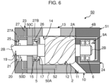
- Fig. 6 in which the same reference numerals as those in Fig. 2 are assigned to parts corresponding to those in Fig. 2 illustrates a vertical cross section of a screw compressor 50 according to a second embodiment.
- a bypass communicating path 52 is configured within a casing 51 (a suction-side casing 50D, a suction-side partition wall 50C, and a main casing 50A) to connect the shaft sealing space 20 and the bore 12 to allow communication therebetween.
- this screw compressor 50 is not provided with the first working chamber liquid supply opening 22 ( Fig. 2 ) in the main casing 50A or a route for connecting the first working chamber liquid supply opening 22 and the bore 12 to allow communication therebetween, so that the lubricating liquid which is supplied to the shaft sealing member 21 inside the shaft sealing space 20 is discharged via the bypass communicating path 52 to inside the bore 12.
- the screw compressor 50 having the above-described configuration according to this embodiment it is possible to supply a sufficient and required amount of the lubricating liquid to the first and second suction-side bearings 5, 7 and the shaft sealing member 21 and keep the stirring loss low at the first and second suction-side bearings 5, 7 in a manner similar to the screw compressor 1 according to the first embodiment. Therefore, the highly reliable and highly efficient screw compressor can be also provided according to this embodiment.
- FIG. 7 in which the same reference numerals as those in Fig. 2 are assigned to parts corresponding to those in Fig. 2 illustrates a vertical cross section of a screw compressor 60 according to a third embodiment.
- This screw compressor 60 is configured in a manner similar to the screw compressor 1 according to the first embodiment, except that the position of a second liquid supply opening 62 is different.
- the second liquid supply opening 62 is provided in a suction-side partition wall 60C so that the lubricating liquid can be supplied from the suction-side partition wall 60C side to the first suction-side bearing 5; and a second branch path 63B of a first liquid supply route 63 is provided inside a suction-side casing 60D and the suction-side partition wall 60C so that the first liquid supply opening 62 and the first suction-side liquid supply opening 23 are connected to each other to allow communication therebetween.
- the lubricating liquid which is supplied from the second liquid supply opening 62 to the first suction-side bearing 5 passes through the rolling element track unit of the first suction-side bearing 5 which performs rotary motions, so that the stirring loss at the first suction-side bearing 5 becomes larger than that of the screw compressor 1 according to the first embodiment.
- this screw compressor 60 is provided with the first liquid supply opening 62 opposite on the suction-side partition wall 60C side relative to the first suction-side bearing 5, so that it is unnecessary to provide, at the main casing 4A, the part to provide the first liquid supply opening opposite the first suction-side bearing 5.
- the lubricating liquid hardly stagnates at the rolling element track unit of the first suction-side bearing 5 and the stirring lost at the first suction-side bearing 5 can be kept low accordingly.
- the screw compressor 60 having the above-described configuration according to this embodiment it is possible to supply a sufficient and required amount of the lubricating liquid to the first suction-side bearing 5 and the shaft sealing member 21 and keep the stirring loss low at the first suction-side bearing 5 in a manner similar to the screw compressor 1 according to the first embodiment. Therefore, the highly reliable and highly efficient screw compressor can be also provided according to this embodiment.
- FIG. 8 in which the same reference numerals as those in Fig. 3 are assigned to parts corresponding to those in Fig. 3 illustrates a vertical cross section of a partial configuration of a screw compressor 70 according to a fourth embodiment.
- This screw compressor 70 is configured in a manner similar to the screw compressor 1 according to the first embodiment, except that a through hole 72 which is designed to insert the suction-side shaft 2B of the male rotor 2 and is formed in a suction-side partition wall 71 is formed to be larger than that of the screw compressor 1 according to the first embodiment.
- the screw compressor 70 having the above-described configuration according to this embodiment it is possible to supply a sufficient and required amount of the lubricating liquid to the first suction-side bearing 5 and the shaft sealing member 21 and keep the stirring loss lower at the first suction-side bearing 5 than that of the screw compressor 1 according to the first embodiment. Therefore, the screw compressor which is highly reliable and more highly efficient can be also provided according to this embodiment.
- the aforementioned first to fourth embodiments have described the case where only the suction-side shaft of the male rotor 2 is connected to the rotating shaft of the motor as the power source; however, the present invention is not limited to this example and the present invention can be also applied to a screw compressor in the form where the suction-side bearing of the female rotor 3, instead of or in addition to the male rotor 2, is connected to the rotating shaft of the power source.
- the aforementioned first to fourth embodiments have described the case where the liquid supply route which is connected to the first liquid supply opening to allow communication therebetween (the first branch path), and the liquid supply route which is connected to the second liquid supply opening to allow communication therebetween (the second branch path) are configured to diverge inside the casing; however, the present invention is not limited to this example and these liquid supply routes may be originally formed separately (openings to which the liquid is supplied from outside may be formed separately).
- the aforementioned third embodiment has described the case where the second liquid supply opening 62 is provided in the suction-side partition wall 60C so that the lubricating liquid can be supplied from the suction-side partition wall 60C side to the first suction-side bearing 5; however, the present invention is not limited to this example and the third liquid supply opening 26 described earlier with reference to Fig. 6 may be provided in the suction-side partition wall 60C so that the lubricating liquid can be also supplied from the suction-side partition wall 60C side to the second suction-side bearing 7.
- the present invention can be applied to a wide variety of screw compressors with various configurations for compressing the working medium.
Landscapes
- Engineering & Computer Science (AREA)
- Mechanical Engineering (AREA)
- General Engineering & Computer Science (AREA)
- Applications Or Details Of Rotary Compressors (AREA)
Abstract
A screw compressor for compressing a working medium is designed to be provided with: first and second screw rotors that suck, compress, and deliver the working medium; a first bearing that freely rotatably supports one end side of the first screw motor whose one end side is coupled to a rotating shaft of a power source; a casing that houses the first screw rotor and the first bearing; a shaft sealing member that is located on an opposite side of a tooth profile unit for the first screw rotor relative to the first bearing inside the casing and seals a through hole in the casing, through which a shaft of the first screw rotor coupled to the output shaft of the power source is inserted; a partition wall that isolates the first bearing from the shaft sealing member inside the casing; and a liquid supply route that is provided in the casing and has a first liquid supply opening for supplying a lubricating liquid to the first bearing and a second liquid supply opening for supplying the lubricating liquid to the shaft sealing member.
Description
- The present invention relates to a screw compressor and is suited for application to a screw compressor including a liquid supplying mechanism.
- Conventionally, there has been known an oil-cooling-type screw compressor disclosed by
PTL 1 as a screw compressor. This screw compressor has a structure such that: it has an oil supply hole for supplying lubricating oil to a space in which a suction bearing and a mechanical seal are stored; and a first collection hole is formed in a partition wall between a screw rotor and a suction-side bearing and a second collection hole is further formed by bypassing the first collection hole, and these first and second collection holes are also open to a compressed air suction passage. - Because of the above-described structure, the screw compressor disclosed by
PTL 1 is designed so that part of the lubricating oil is collected through the second collection hole, thereby minimizing an amount of the lubricating oil, which passes through the suction-side bearing, as required for lubrication purpose and making it possible to reduce stirring loss of the suction-side bearing. - PTL 1:
Japanese Patent Application Laid-Open (Kokai) Publication No. 2002-21758 - Meanwhile, with the screw compressor disclosed by
PTL 1, the bearing is lubricated through the process of part of the lubricating oil accumulated in the space, in which the suction-side bearing and the mechanical seal are stored, passing through the suction-side bearing and being collected in the first collection hole. - Accordingly, the structure is in principle designed so that the suction-side bearing stirs the lubricating oil, which has accumulated in the space, and also stirs the lubricating oil which passes through the suction-side bearing, thereby resulting in a problem of large stirring loss which is caused particularly by stirring of the lubricating oil accumulated in the space, wherein the large stirring loss causes degradation of performance as the compressor.
- The present invention was devised in consideration of the above-described circumstances and aims at proposing a highly reliable and highly efficient screw compressor capable of effectively preventing the degradation of performance as the compressor.
- In order to solve the above-described problems, there is provided according to the present invention a screw compressor for compressing a working medium, which is designed to be provided with: first and second screw rotors that suck, compress, and deliver the working medium; a first bearing that freely rotatably supports one end side of the first screw rotor whose one end side is coupled to a rotating shaft of a power source; a casing that houses the first screw rotor and the first bearing; a shaft sealing member that is located on an opposite side of a tooth profile unit for the first screw rotor relative to the first bearing inside the casing and seals a through hole in the casing, through which a shaft of the first screw rotor coupled to the output shaft of the power source is inserted; a partition wall that isolates the first bearing from the shaft sealing member inside the casing; and a liquid supply route that is provided in the casing and has a first liquid supply opening for supplying a lubricating liquid to the first bearing and a second liquid supply opening for supplying the lubricating liquid to the shaft sealing member.
- As a result, an appropriate amount of the lubricating liquid can be supplied to the shaft sealing member and the first bearing respectively independently. Consequently, it is possible to suppress the stirring loss of the lubricating liquid at the first bearing which is attributable to the supply of an excessive amount of the lubricating liquid to the first bearing.
- The highly reliability and highly efficient screw compressor can be realized according to the present invention.
-
-
Fig. 1 is a horizontal-direction sectional view illustrating a male-rotor-side configuration of a screw compressor according to a first embodiment; -
Fig. 2 is a vertical-direction sectional view illustrating the male-rotor-side configuration of the screw compressor according to the first embodiment; -
Fig. 3 is a vertical-direction sectional view illustrating the configuration of a liquid supply route on the male rotor side of the screw compressor according to the first embodiment; -
Fig. 4 is a vertical-direction sectional view illustrating a female-rotor-side configuration of the screw compressor according to the first embodiment; -
Fig. 5 is a conceptual diagram for explaining an external route for a lubricating liquid injected into the screw compressor according to the first embodiment; -
Fig. 6 is a vertical-direction sectional view illustrating a male-rotor-side configuration of a screw compressor according to a second embodiment; -
Fig. 7 is a vertical-direction sectional view illustrating a male-rotor-side configuration of a screw compressor according to a third embodiment; and -
Fig. 8 is a vertical-direction sectional view illustrating a male-rotor-side configuration of a screw compressor according to a fourth embodiment. - One embodiment of the present invention will be described below in detail with reference to the drawings.
-
Fig. 1 andFig. 2 illustrate ascrew compressor 1 according to a first embodiment.Fig. 1 is a diagram taken along line C-C indicated with arrows inFig. 2 (a horizontal sectional view) andFig. 2 is a diagram taken along line A-A indicated with arrows inFig. 1 (a vertical sectional view). - The
screw compressor 1 according to this embodiment is configured, as illustrated inFig. 1 andFig. 2 , by including amale rotor 2 and afemale rotor 3 which constitute a pair of screw rotors, and acasing 4 for housing themale rotor 2 and thefemale rotor 3. - The
male rotor 2 is configured by including atooth profile unit 2A on which a plurality of spirally extending teeth (lobes) are formed, a suction-side shaft 2B formed on one end side (the left side inFig. 1 andFig. 2 and the same applies hereinafter) of thetooth profile unit 2A in its rotor shaft direction, and a delivery-side shaft 2C on the other end side (the right side inFig. 1 andFig. 2 and the same applies hereinafter) of thetooth profile unit 2A in its rotor shaft direction. The suction-side shaft 2B of themale rotor 2 is freely rotatably supported by a suction-side bearing (hereinafter referred to as a "first suction-side bearing") 5 and the delivery-side shaft 2C of themale rotor 2 is freely rotatably supported by a delivery-side bearing (hereinafter referred to as a "first delivery-side bearing") 6. - Similarly, the
female rotor 3 is configured by including atooth profile unit 3A with a plurality of lobes formed thereon which mesh with the lobes of themale rotor 2, a suction-side shaft 3B formed on one end side of thetooth profile unit 3A in its rotor shaft direction, and a delivery-side shaft 3C formed on the other end side of thetooth profile unit 3A in its rotor shaft direction. The suction-side shaft 3B of thefemale rotor 3 is freely rotatably supported by a suction-side bearing (hereinafter referred to as a "second suction-side bearing") 7 and the delivery-side shaft 3C of thefemale rotor 3 is freely rotatably supported by the delivery-side bearing (hereinafter referred to as a "second delivery-side bearing") 8. - The suction-
side shaft 2B of themale rotor 2 pierces through thecasing 4 and is coupled to a rotating shaft of a motor which is not illustrated in the drawing. Accordingly, by driving the motor, themale rotor 2 can be rotatably driven integrally with the rotating shaft of the motor; and accordingly, thefemale rotor 3 can be also rotatably driven integrally with themale rotor 2. - The
casing 4 is composed of amain casing 4A, a delivery-side casing 4B coupled to the other end side of themain casing 4A in its rotor shaft direction, and a suction-side casing 4D coupled via a suction-side partition wall 4C to one end side of themain casing 4A in its rotor shaft direction. - The delivery-
side casing 4B is provided with a first delivery-side bearinghousing space 9A and a second delivery-side bearinghousing space 9B which are provided mutually independently; and the first delivery-side bearing 6 is housed in the first delivery-side bearinghousing space 9A and the second delivery-side bearing 8 is housed in the second delivery-side bearinghousing space 9B. Moreover, a delivery opening 10 positioned outside thetooth profile units male rotor 2 and thefemale rotor 3 in their rotor diameter direction (the lower side inFig. 2 ) and adelivery passage 11 which connects the delivery opening 10 and abore 12 described later are formed in the delivery-side casing 4B. - The
bore 12 which houses thetooth profile unit 2A of themale rotor 2 and thetooth profile unit 3A of thefemale rotor 3 is formed in themain casing 4A. Thebore 12 is a space, which has a shape of two cylindrical holes partially overlapping with each other, for housing thetooth profile unit 2A of themale rotor 2 and thetooth profile unit 3A of thefemale rotor 3 in a state of their lobes meshing with each other. - A working chamber is formed of an inner wall surface of the
bore 12, a groove of themale rotor 2, and a groove of thefemale rotor 3. The working chamber is formed so that its volume gradually decreases from its one end side to the other end side in the rotor shaft direction. Accordingly, the working medium such as air sucked through a suction opening 13 is gradually compressed in the working chamber and is then delivered from the delivery opening 10 through thedelivery passage 11. - The
suction opening 13 is formed outside in the rotor diameter direction of thetooth profile unit 2A of themale rotor 2 and thetooth profile unit 3A of thefemale rotor 3 in themain casing 4A (the upper side inFig. 2 ). Thesuction opening 13 is connected to the working chamber via asuction space 14 to allow communication therebetween and the working medium sucked through the suction opening 13 passes through thesuction space 14 and is supplied to the working chamber via thesuction space 14. - A cylindrical first suction-side bearing
housing space 15 and a cylindrical second suction-side bearinghousing space 16 are formed in an end face on the one end side of themain casing 4A in the rotor shaft direction. Then, the first suction-side bearing 5 is housed in the first suction-side bearinghousing space 15 so that first suction-side bearing 5 is fitted into the first suction-side bearinghousing space 15; and the second suction-side bearing 7 is housed in the second suction-side bearinghousing space 16 so that the second suction-side bearing 7 is fitted into the second suction-side bearinghousing space 16. - Moreover, a first bearing communicating
space 17 which has a slightly smaller diameter than that of the first suction-side bearinghousing space 15 and connects the first suction-side bearinghousing space 15 and thesuction space 14 to allow communication therebetween, and a second bearing communicatingspace 18 which has a slightly smaller diameter than that of the second suction-side bearinghousing space 16 and connects the second suction-side bearinghousing space 16 and thesuction space 14 to allow communication therebetween are formed in themain casing 4A. - Furthermore, the suction-
side partition wall 4C is secured to the end face on the one end side of themain casing 4A in the rotor shaft direction and the suction-side casing 4D is secured to an end of this suction-side partition wall 4C in the rotor shaft direction. Then, ashaft sealing space 20 which is connected to a throughhole 19, into which the suction-side shaft 2B of themale rotor 2 is inserted, to allow communication therebetween is formed on a surface opposite the suction-side partition wall 4C and ashaft sealing member 21 for sealing the throughhole 19 is disposed inside thisshaft sealing space 20. - In addition, the
casing 4 of thisscrew compressor 1 is provided with a first working chamberliquid supply opening 22 which is connected to the working chamber inside thebore 12 to allow communication therebetween, so that liquid can be injected into the working chamber through this first working chamber liquid supply opening 22. Moreover, a first suction-sideliquid supply opening 23 is provided on the suction opening 13 side of thecasing 4 and a first delivery-sideliquid supply opening 24 is provided on the delivery opening 10 side of thecasing 4, so that a liquid can be injected into theshaft sealing space 20 and into the first suction-side bearinghousing space 15, respectively, through the first suction-side liquid supply opening 23 and the liquid can be injected into the first delivery-side bearinghousing space 9A through the first delivery-side liquid supply opening 24. - The purpose of the above-described injection of the liquid to the working chamber, the
shaft sealing space 20, the first suction-side bearinghousing space 15, and the first delivery-side bearinghousing space 9A is to cool mechanism components and compressed air, lubricate the first suction-side bearing 5 and the first delivery-side bearing 6, and enhance sealability by theshaft sealing member 21; and oil or water is applied as the liquid to be then injected. This liquid will be hereinafter referred to as a "lubricating liquid." - The lubricating liquid injected into the first suction-side liquid supply opening 23 passes through inside of the
casing 4 and is emitted through a first liquid supply opening 25 into theshaft sealing space 20 and is also emitted through a second liquid supply opening 26 into the first suction-side bearinghousing space 15. -
Fig. 3 illustrates a distribution route inside thecasing 4 for the lubricating liquid supplied to the first suction-side bearing 5 and theshaft sealing member 21. Arrows in the drawing indicate liquid supply directions of the lubricating liquid. A firstliquid supply route 27 which connects the first suction-side liquid supply opening 23 and the first and secondliquid supply openings casing 4 as illustrated in thisFig. 3 . Moreover, the firstliquid supply route 27 is formed so that it diverges into first andsecond branch paths first branch path 27A connects to the first liquid supply opening 25 to allow communication therebetween and thesecond branch path 27B connects to the second liquid supply opening 26 to allow communication therebetween. - In this case, the first
liquid supply opening 25 is open toward theshaft sealing member 21 located inside theshaft sealing space 20. Accordingly, the lubricating liquid which is injected through the first suction-side liquid supply opening 23 into thecasing 4 and then flows into thefirst branch path 27A is emitted from the first liquid supply opening 25 and then supplied to theshaft sealing member 21. Moreover, theshaft sealing space 20 is connected to thesuction space 14 via abypass communicating path 28 to allow communication therebetween. Accordingly, the lubricating liquid injected into theshaft sealing space 20 is discharged to thesuction space 14 through thebypass communicating path 28. - On the other hand, the second
liquid supply opening 26 is open toward the first suction-side bearing 5 which is housed in the first suction-side bearinghousing space 15. Accordingly, the lubricating liquid which is injected through the first suction-sideliquid supply opening 23 into thecasing 4 and flows into thesecond branch path 27B is emitted from the secondliquid supply opening 26 and is then supplied from themale rotor 2 side to the first suction-side bearing 5. - In this case, the first suction-
side bearing 5 is partially exposed to thesuction space 14 via the firstbearing communicating space 17 of themain casing 4A, so that the lubricating liquid which is supplied from the secondliquid supply opening 26 to the first suction-side bearing 5 flows out to thesuction space 14 via the firstbearing communicating space 17. Subsequently, this lubricating liquid joins the lubricating liquid, which has flown into thesuction space 14 via thebypass communicating path 28, and is then delivered, together with the working medium which has flown into thesuction space 14 through thesuction opening 13, to the working chamber. - Now, stirring loss of the lubricating liquid at the first suction-
side bearing 5 will be examined. In this embodiment, a roller bearing is assumed as the first suction-side bearing 5; however, the invention is not limited to this example and the first suction-side bearing 5 may be other antifriction bearings such as a ball bearing. - Generally, when an antifriction bearing rotates in the lubricating liquid, a rolling element within the antifriction bearing rolls while pushing away the lubricating liquid, and the rolling element thereby becomes subject to fluid resistance. Also, this embodiment has such a structure that the lubricating liquid supplied to the first suction-
side bearing 5 is always replaced, so that the rolling element needs to perform work to accelerate the lubricating liquid which has newly flown in. A combination of these results in the stirring loss. - This embodiment has such a structure as is obvious from
Fig. 3 that the position where the first suction-side bearing 5 is located is higher than the position of the lowest end of thesuction space 14 and the lubricating liquid can be hardly accumulated. Also, when thisscrew compressor 1 is installed so that themale rotor 2 and thefemale rotor 3 are positioned horizontally as inFig. 3 , the firstbearing communicating space 17 is formed so that the lowest end of the firstbearing communicating space 17 becomes lower than a height position of the lowest end of an outer ring bore diameter of the first suction-side bearing 5; and, accordingly, it is structured so that the lubricating liquid inside a rolling element track unit of the first suction-side bearing 5 can be easily discharged. - Furthermore, for example, if the second
liquid supply opening 26 is formed on the suction-side partition wall 4C side, the lubricating liquid which is supplied to the first suction-side bearing 5 through this secondliquid supply opening 26 needs to pass through inside the rolling element track unit of the first suction-side bearing 5, which performs rotary motions, in order for this lubricating liquid to flow out to thesuction space 14 side. So, the stirring loss will increase accordingly. On the other hand, in this embodiment, the secondliquid supply opening 26 is formed so that the lubricating liquid can be supplied from themale rotor 2 side to the first suction-side bearing 5; and, therefore, the entire lubricating liquid supplied to the first suction-side bearing 5 does not have to pass through the rolling element track unit of the first suction-side bearing 5 which performs the rotary motions. Consequently, it can be said that thisscrew compressor 1 has the structure with small stirring loss of the lubricating liquid in the rolling element track unit of the first suction-side bearing 5. - Next, an explanation will be provided about a liquid supply amount of the lubricating liquid to the
shaft sealing member 21 and the first suction-side bearing 5. As described in theaforementioned PTL 1, a required amount of the lubricating liquid at the first suction-side bearing 5 is generally smaller than that at theshaft sealing member 21 such as a mechanical seal. - Regarding this point, with the
screw compressor 1 according to this embodiment, the first suction-side bearinghousing space 15 which houses the first suction-side bearing 5, and theshaft sealing space 20 in which theshaft sealing member 21 is disposed are isolated from each other by the suction-side partition wall 4C and the firstliquid supply opening 25 for supplying the lubricating liquid to theshaft sealing member 21 and the secondliquid supply opening 26 for supplying the lubricating liquid to the first suction-side bearing 5 are provided independently, so that an appropriate amount of the lubricating liquid can be supplied respectively to theshaft sealing member 21 and the first suction-side bearing 5. - Allocations of the liquid supply amount of the lubricating liquid to the
shaft sealing member 21 and the first suction-side bearing 5 can be decided by pressure loss of the firstliquid supply route 27 and, specifically speaking, can be decided according to the lengths and hydraulic diameters of the first andsecond branch paths liquid supply openings shaft sealing member 21 as described above is larger than the supply amount of the lubricating liquid required for the first suction-side bearing 5, so that the lengths and hydraulic diameters of the first andsecond branch paths liquid supply openings liquid supply opening 23 to the firstliquid supply opening 25 become smaller than the pressure loss from the first suction-sideliquid supply opening 23 to the secondliquid supply opening 26. -
Fig. 4 is a diagram taken along line B-B indicated with arrows inFig. 1 (a vertical sectional view). Themain casing 4A is provided with a second working chamberliquid supply opening 30 which is connected to the working chamber in thebore 12 to allow communication therebetween, so that it is designed to enable the lubricating liquid to be supplied from outside thescrew compressor 1 through the second working chamberliquid supply opening 30 to the working chamber. - Additionally, a second delivery-side
liquid supply opening 31 is formed in the delivery-side casing 4B, so that it is designed to enable the lubricating liquid to be supplied to the second delivery-side bearing 8, which is disposed within the second delivery-side bearinghousing space 9B, through this second delivery-sideliquid supply opening 31. - Furthermore, a second suction-side
liquid supply opening 32 is formed outside in the rotor diameter direction of the suction-side casing 4D and themain casing 4A is provided with a thirdliquid supply opening 33 toward the second suction-side bearing 7, which is housed in the second suction-side bearinghousing space 16, and the thirdliquid supply opening 33 is connected to the second suction-sideliquid supply opening 32 to allow communication therebetween via a secondliquid supply route 34 formed inside thecasing 4. Accordingly, it is designed so that this lubricating liquid can be supplied from the thirdliquid supply opening 33 to the second suction-side bearing 7 by way of the secondliquid supply route 34 by injecting the lubricating liquid into thescrew compressor 1 through the second suction-sideliquid supply opening 32. - In this case, the second suction-
side bearing 7 is partially exposed to thesuction space 14 via the secondbearing communicating space 18 of themain casing 4A, the lubricating liquid which is supplied from the second suction-sideliquid supply opening 32 via the secondliquid supply route 34 to the second suction-side bearing 7 flows out to thesuction space 14 via the secondbearing communicating space 18 and is then delivered to the working chamber together with the working medium which has flown from thesuction opening 13 into thesuction space 14. - By configuring the second
liquid supply route 34 as described above, it is possible to keep the stirring loss of the lubricating liquid small at the second suction-side bearing 7 by means of the mechanism similar to that of the stirring loss of the lubricating liquid at the first suction-side bearing 5. - Incidentally, the second working chamber
liquid supply opening 30, the second suction-sideliquid supply opening 32, and the second delivery-sideliquid supply opening 31 may be formed respectively separately from their corresponding openings, that is, the first working chamberliquid supply opening 22, the first suction-sideliquid supply opening 23, and the first delivery-sideliquid supply opening 24 described earlier with reference toFig. 2 , or may be provided at the same positions as those of the above-mentioned openings. In other words, the first and second working chamberliquid supply openings liquid supply openings liquid supply openings -
Fig. 5 illustrates an external route for the lubricating liquid injected into thescrew compressor 1 according to this embodiment. The lubricating liquid injected into thescrew compressor 1 is delivered through the delivery opening 10 (Fig. 2 andFig. 4 ) in a state of being mixed into the working medium compressed by thescrew compressor 1. Then, after this lubricating liquid is separated from the working medium, which is compressed by anoil separator 40, and is cooled by a cooler 41, the lubricating liquid goes through an oil filter (and a check valve) 42 and is then given to the first and second working chamberliquid supply openings 22, 30 (Fig. 2 andFig. 4 ) and is injected into the working chamber through these first and second working chamberliquid supply openings - Furthermore, after passing through the
oil filter 42, the lubricating liquid is made to diverge, is given to the first and second suction-sideliquid supply openings 23, 32 (Fig. 2 andFig. 4 ) and also the first and second delivery-sideliquid supply openings 24, 31 (Fig. 2 andFig. 4 ), and is also supplied, through the first suction-sideliquid supply opening 23, to the shaft sealing member 21 (Fig. 2 ) inside the shaft sealing space 20 (Fig. 2 ), to the first suction-side bearing 5 inside the first suction-side bearing housing space 15 (Fig. 2 ), to the second suction-side bearing 7 inside the first suction-side bearing housing space 15 (Fig. 2 ), to the first delivery-side bearing 6 (Fig. 1 ) which is housed in the first delivery-side bearinghousing space 9A (Fig. 1 ), and to the second delivery-side bearing 8 (Fig. 1 ) which is housed in the second delivery-side bearinghousing space 9B (Fig. 1 ), respectively. Incidentally, the divergence of the lubricating liquid is not limited to outside thescrew compressor 1 as illustrated inFig. 5 , but the lubricating liquid may diverge inside thecasing 4 of thescrew compressor 1. - With the
screw compressor 1 according to this embodiment which has the above-described configuration, the first suction-side bearinghousing space 15 which houses the first suction-side bearing 5, and theshaft sealing space 20 in which theshaft sealing member 21 is disposed are isolated from each other by the suction-side partition wall 4C and the firstliquid supply opening 25 for supplying the lubricating liquid to theshaft sealing member 21 and the secondliquid supply opening 26 for supplying the lubricating liquid to the first suction-side bearing 5 are provided independently, so that an appropriate amount of the lubricating liquid can be supplied independently to theshaft sealing member 21 and the first suction-side bearing 5, respectively. Therefore, if thisscrew compressor 1 is employed, it is possible to suppress the stirring loss of the lubricating liquid at the first suction-side bearing 5, which is attributable to the supply of an excessive amount of the lubricating liquid to the first suction-side bearing 5, and it is thereby possible to realize the highly reliable and highly efficient screw compressor. - Furthermore, with this
screw compressor 1, the secondliquid supply opening 26 is formed so that the lubricating liquid can be supplied from themale rotor 2 side to the first suction-side bearing 5. So, the entire lubricating liquid supplied to the first suction-side bearing 5 does not have to pass through the rolling element track unit of the first suction-side bearing 5 which performs rotary motions. Consequently, if thisscrew compressor 1 is employed, it is possible to realize the screw compressor which has small stirring loss of the lubricating liquid at the first suction-side bearing 5 and which is more highly efficient. -
Fig. 6 in which the same reference numerals as those inFig. 2 are assigned to parts corresponding to those inFig. 2 illustrates a vertical cross section of ascrew compressor 50 according to a second embodiment. The difference between thisscrew compressor 50 and thescrew compressor 1 according to the first embodiment is that abypass communicating path 52 is configured within a casing 51 (a suction-side casing 50D, a suction-side partition wall 50C, and amain casing 50A) to connect theshaft sealing space 20 and thebore 12 to allow communication therebetween. - Accordingly, this
screw compressor 50 is not provided with the first working chamber liquid supply opening 22 (Fig. 2 ) in themain casing 50A or a route for connecting the first working chamberliquid supply opening 22 and thebore 12 to allow communication therebetween, so that the lubricating liquid which is supplied to theshaft sealing member 21 inside theshaft sealing space 20 is discharged via thebypass communicating path 52 to inside thebore 12. - If the
screw compressor 50 having the above-described configuration according to this embodiment is employed, it is possible to supply a sufficient and required amount of the lubricating liquid to the first and second suction-side bearings shaft sealing member 21 and keep the stirring loss low at the first and second suction-side bearings screw compressor 1 according to the first embodiment. Therefore, the highly reliable and highly efficient screw compressor can be also provided according to this embodiment. -
Fig. 7 in which the same reference numerals as those inFig. 2 are assigned to parts corresponding to those inFig. 2 illustrates a vertical cross section of ascrew compressor 60 according to a third embodiment. Thisscrew compressor 60 is configured in a manner similar to thescrew compressor 1 according to the first embodiment, except that the position of a secondliquid supply opening 62 is different. - Practically, regarding the
screw compressor 60 according to this embodiment, the secondliquid supply opening 62 is provided in a suction-side partition wall 60C so that the lubricating liquid can be supplied from the suction-side partition wall 60C side to the first suction-side bearing 5; and asecond branch path 63B of a firstliquid supply route 63 is provided inside a suction-side casing 60D and the suction-side partition wall 60C so that the firstliquid supply opening 62 and the first suction-sideliquid supply opening 23 are connected to each other to allow communication therebetween. - Accordingly, with this
screw compressor 60, the lubricating liquid which is supplied from the secondliquid supply opening 62 to the first suction-side bearing 5 passes through the rolling element track unit of the first suction-side bearing 5 which performs rotary motions, so that the stirring loss at the first suction-side bearing 5 becomes larger than that of thescrew compressor 1 according to the first embodiment. - However, this
screw compressor 60 is provided with the firstliquid supply opening 62 opposite on the suction-side partition wall 60C side relative to the first suction-side bearing 5, so that it is unnecessary to provide, at themain casing 4A, the part to provide the first liquid supply opening opposite the first suction-side bearing 5. As a result, it is possible to secure a large opening area for the firstbearing communicating space 17. So, the lubricating liquid hardly stagnates at the rolling element track unit of the first suction-side bearing 5 and the stirring lost at the first suction-side bearing 5 can be kept low accordingly. - If the
screw compressor 60 having the above-described configuration according to this embodiment is employed, it is possible to supply a sufficient and required amount of the lubricating liquid to the first suction-side bearing 5 and theshaft sealing member 21 and keep the stirring loss low at the first suction-side bearing 5 in a manner similar to thescrew compressor 1 according to the first embodiment. Therefore, the highly reliable and highly efficient screw compressor can be also provided according to this embodiment. -
Fig. 8 in which the same reference numerals as those inFig. 3 are assigned to parts corresponding to those inFig. 3 illustrates a vertical cross section of a partial configuration of ascrew compressor 70 according to a fourth embodiment. Thisscrew compressor 70 is configured in a manner similar to thescrew compressor 1 according to the first embodiment, except that a throughhole 72 which is designed to insert the suction-side shaft 2B of themale rotor 2 and is formed in a suction-side partition wall 71 is formed to be larger than that of thescrew compressor 1 according to the first embodiment. - So, regarding the
screw compressor 70 according to this embodiment, while most of the lubricating liquid supplied through the secondliquid supply opening 26 to the first suction-side bearing 5 flows out to thesuction space 14, part of the rest of the lubricating liquid passes through the first suction-side bearing 5, goes through the throughhole 72 and flows into theshaft sealing space 20, and then joins the lubricating liquid, which has been supplied to theshaft sealing space 20 through the firstliquid supply opening 25, and goes through thebypass communicating path 28 and is discharged to thesuction space 14. - Accordingly, with this
screw compressor 70, part of the lubricating liquid which has been supplied through the secondliquid supply opening 26 to the first suction-side bearing 5 passes through the rolling element track unit of the first suction-side bearing 5 which performs the rotary motions, but the lubricating liquid which passes through the rolling element track unit of the first suction-side bearing 5 promptly flows into theshaft sealing space 20 through the throughhole 72. So, the lubricating liquid hardly stagnates at the rolling element track unit of the first suction-side bearing 5 and the stirring lost at the first suction-side bearing 5 can be kept lower than that of thescrew compressor 1 according to the first embodiment. - If the
screw compressor 70 having the above-described configuration according to this embodiment is employed, it is possible to supply a sufficient and required amount of the lubricating liquid to the first suction-side bearing 5 and theshaft sealing member 21 and keep the stirring loss lower at the first suction-side bearing 5 than that of thescrew compressor 1 according to the first embodiment. Therefore, the screw compressor which is highly reliable and more highly efficient can be also provided according to this embodiment. - Incidentally, the aforementioned first to fourth embodiments have described the case where only the suction-side shaft of the
male rotor 2 is connected to the rotating shaft of the motor as the power source; however, the present invention is not limited to this example and the present invention can be also applied to a screw compressor in the form where the suction-side bearing of thefemale rotor 3, instead of or in addition to themale rotor 2, is connected to the rotating shaft of the power source. - Moreover, the aforementioned first to fourth embodiments have described the case where the liquid supply route which is connected to the first liquid supply opening to allow communication therebetween (the first branch path), and the liquid supply route which is connected to the second liquid supply opening to allow communication therebetween (the second branch path) are configured to diverge inside the casing; however, the present invention is not limited to this example and these liquid supply routes may be originally formed separately (openings to which the liquid is supplied from outside may be formed separately).
- Furthermore, the aforementioned third embodiment has described the case where the second
liquid supply opening 62 is provided in the suction-side partition wall 60C so that the lubricating liquid can be supplied from the suction-side partition wall 60C side to the first suction-side bearing 5; however, the present invention is not limited to this example and the thirdliquid supply opening 26 described earlier with reference toFig. 6 may be provided in the suction-side partition wall 60C so that the lubricating liquid can be also supplied from the suction-side partition wall 60C side to the second suction-side bearing 7. - The present invention can be applied to a wide variety of screw compressors with various configurations for compressing the working medium.
-
- 1, 50, 60, 70: screw compressor
- 2: male rotor
- 2A, 3A: tooth profile units
- 2B, 3B: suction-side shafts
- 2C, 3C: delivery-side shafts
- 3: female rotor
- 4, 51: casing
- 5, 7: suction-side bearings
- 6, 8: delivery-side bearings
- 9A, 9B: delivery-side bearing housing spaces
- 10: delivery opening
- 12: bore
- 13: suction opening
- 14: suction space
- 15, 16: suction-side bearing housing spaces
- 17, 18, 72: bearing communicating spaces
- 19: through hole
- 20: shaft sealing space
- 21: shaft sealing member
- 22, 30: working chamber liquid supply openings
- 23, 32: suction-side liquid supply openings
- 24, 31: delivery-side liquid supply openings
- 25, 26, 33, 62: liquid supply openings
- 27, 34, 63: liquid supply routes
- 27A, 27B, 63A, 63B: branch paths
- 28, 52: bypass communicating paths
Claims (6)
- A screw compressor for compressing a working medium, comprising:first and second screw rotors that suck, compress, and deliver the working medium;a first bearing that freely rotatably supports one end side of the first screw rotor whose one end side is coupled to a rotating shaft of a power source;a casing that houses the first screw rotor and the first bearing;a shaft sealing member that is located on an opposite side of a tooth profile unit for the first screw rotor relative to the first bearing inside the casing and seals a through hole in the casing, through which a shaft of the first screw rotor coupled to the output shaft of the power source is inserted;a partition wall that isolates the first bearing from the shaft sealing member inside the casing; anda liquid supply route that is provided in the casing and has a first liquid supply opening for supplying a lubricating liquid to the first bearing and a second liquid supply opening for supplying the lubricating liquid to the shaft sealing member.
- The screw compressor according to claim 1,wherein the shaft sealing member is disposed in a first space provided in the casing;wherein the first bearing is disposed in a second space provided in the casing;wherein the tooth profile unit with lobes formed thereon in the screw rotor with its one end side coupled to the rotating shaft of the power source is housed in a third space;wherein the first space is isolated from the second space by the partition wall;wherein the first space is connected to the third space to allow communication therebetween via a bypass communicating path; andwherein the lubricating liquid supplied to the first space is discharged to the third space via the bypass path.
- The screw compressor according to claim 1,
wherein the first liquid supply opening is formed in the casing to supply the lubricating liquid to the first bearing from the screw rotor's side. - The screw compressor according to claim 2,comprising a communicating space which connects the second space and the third space to allow communication therebetween,wherein the lubricating liquid which is supplied to the first bearing is discharged to the third space via the communicating space.
- The screw compressor according to claim 4,
wherein the communicating space is formed so that when the first rotor and the second screw rotor are installed horizontally, a lowest end of the communicating space becomes lower than a lower-end position of an outer ring bore diameter of the first bearing. - The screw compressor according to claim 1, comprising:a second bearing that freely rotatably supports an one end side of the second screw rotor which is the same as the one end side of the first screw rotor coupled to the rotating shaft of the power source; anda third liquid supply opening provided in the casing to supply the lubricating liquid to the second bearing,wherein the third liquid supply opening is formed in the casing to supply the lubricating liquid from the screw rotors' side to the first bearing.
Applications Claiming Priority (2)
| Application Number | Priority Date | Filing Date | Title |
|---|---|---|---|
| JP2021092296A JP2022184443A (en) | 2021-06-01 | 2021-06-01 | screw compressor |
| PCT/JP2022/021846 WO2022255275A1 (en) | 2021-06-01 | 2022-05-27 | Screw compressor |
Publications (1)
| Publication Number | Publication Date |
|---|---|
| EP4350146A1 true EP4350146A1 (en) | 2024-04-10 |
Family
ID=84324191
Family Applications (1)
| Application Number | Title | Priority Date | Filing Date |
|---|---|---|---|
| EP22816023.0A Pending EP4350146A1 (en) | 2021-06-01 | 2022-05-27 | Screw compressor |
Country Status (4)
| Country | Link |
|---|---|
| EP (1) | EP4350146A1 (en) |
| JP (1) | JP2022184443A (en) |
| CN (1) | CN116710655A (en) |
| WO (1) | WO2022255275A1 (en) |
Families Citing this family (1)
| Publication number | Priority date | Publication date | Assignee | Title |
|---|---|---|---|---|
| JP2024025321A (en) * | 2022-08-12 | 2024-02-26 | 株式会社日立産機システム | oil-cooled screw compressor |
Family Cites Families (2)
| Publication number | Priority date | Publication date | Assignee | Title |
|---|---|---|---|---|
| JP4066038B2 (en) | 2000-07-11 | 2008-03-26 | 株式会社日立産機システム | Oil-cooled screw compressor |
| JPWO2007000815A1 (en) * | 2005-06-29 | 2009-01-22 | 株式会社前川製作所 | Lubricating method for two-stage screw compressor, device and operating method for refrigerating device |
-
2021
- 2021-06-01 JP JP2021092296A patent/JP2022184443A/en active Pending
-
2022
- 2022-05-27 CN CN202280008601.XA patent/CN116710655A/en active Pending
- 2022-05-27 EP EP22816023.0A patent/EP4350146A1/en active Pending
- 2022-05-27 WO PCT/JP2022/021846 patent/WO2022255275A1/en active Application Filing
Also Published As
| Publication number | Publication date |
|---|---|
| CN116710655A (en) | 2023-09-05 |
| WO2022255275A1 (en) | 2022-12-08 |
| JP2022184443A (en) | 2022-12-13 |
Similar Documents
| Publication | Publication Date | Title |
|---|---|---|
| CN111133197B (en) | Scroll compressor having a scroll compressor with a suction chamber | |
| JP5178668B2 (en) | Scroll compressor | |
| EP4350146A1 (en) | Screw compressor | |
| EP3418569B1 (en) | Open-type refrigerant compressor | |
| CN116857189A (en) | Compressor with axial flexibility | |
| JP2007085297A (en) | Scroll compressor | |
| JP4611129B2 (en) | Compressor | |
| JP2003227480A (en) | Scroll-type compressor | |
| JP7229720B2 (en) | screw compressor | |
| JPH08200244A (en) | Scroll type compressor | |
| JP2010190078A (en) | Compressor | |
| JP2017025789A (en) | Rotary compressor | |
| KR100186875B1 (en) | Rotary vane type compressor and vacuum pump | |
| JP4848844B2 (en) | Electric compressor | |
| JP2007132233A (en) | Scroll compressor | |
| CN111140495B (en) | Scroll compressor having a rotor with a rotor shaft having a rotor shaft with a | |
| JP2017172484A (en) | Scroll compressor | |
| JP2007162679A (en) | Fluid machine | |
| JP2009127440A (en) | Scroll compressor | |
| JP2006241993A (en) | Scroll compressor | |
| JP2020007982A (en) | Two-stage screw fluid machine | |
| JPH0783185A (en) | Horizontal rotary compressor | |
| JPH0953583A (en) | Oil-cooled screw two-stage compressor | |
| WO2024034235A1 (en) | Oil-cooled screw compressor | |
| CN102822524B (en) | Electrically driven gas compressor |
Legal Events
| Date | Code | Title | Description |
|---|---|---|---|
| STAA | Information on the status of an ep patent application or granted ep patent |
Free format text: STATUS: THE INTERNATIONAL PUBLICATION HAS BEEN MADE |
|
| PUAI | Public reference made under article 153(3) epc to a published international application that has entered the european phase |
Free format text: ORIGINAL CODE: 0009012 |
|
| STAA | Information on the status of an ep patent application or granted ep patent |
Free format text: STATUS: REQUEST FOR EXAMINATION WAS MADE |
|
| 17P | Request for examination filed |
Effective date: 20240102 |
|
| AK | Designated contracting states |
Kind code of ref document: A1 Designated state(s): AL AT BE BG CH CY CZ DE DK EE ES FI FR GB GR HR HU IE IS IT LI LT LU LV MC MK MT NL NO PL PT RO RS SE SI SK SM TR |
|
| DAV | Request for validation of the european patent (deleted) | ||
| DAX | Request for extension of the european patent (deleted) |