EP4350129A1 - Integrated organic rankine cycle and absorption cycle power generation system - Google Patents
Integrated organic rankine cycle and absorption cycle power generation system Download PDFInfo
- Publication number
- EP4350129A1 EP4350129A1 EP23201246.8A EP23201246A EP4350129A1 EP 4350129 A1 EP4350129 A1 EP 4350129A1 EP 23201246 A EP23201246 A EP 23201246A EP 4350129 A1 EP4350129 A1 EP 4350129A1
- Authority
- EP
- European Patent Office
- Prior art keywords
- cycle
- condenser
- evaporator
- absorption
- orc
- Prior art date
- Legal status (The legal status is an assumption and is not a legal conclusion. Google has not performed a legal analysis and makes no representation as to the accuracy of the status listed.)
- Pending
Links
- 238000010521 absorption reaction Methods 0.000 title claims abstract description 101
- 238000010248 power generation Methods 0.000 title 1
- 239000012530 fluid Substances 0.000 claims abstract description 125
- 239000006096 absorbing agent Substances 0.000 claims abstract description 61
- 238000004519 manufacturing process Methods 0.000 claims abstract description 21
- 239000012224 working solution Substances 0.000 claims abstract description 18
- 238000001816 cooling Methods 0.000 claims description 23
- 238000011084 recovery Methods 0.000 claims description 16
- 238000009833 condensation Methods 0.000 claims description 11
- 230000005494 condensation Effects 0.000 claims description 11
- 230000008901 benefit Effects 0.000 claims description 8
- XLYOFNOQVPJJNP-UHFFFAOYSA-N water Substances O XLYOFNOQVPJJNP-UHFFFAOYSA-N 0.000 claims description 7
- 238000000034 method Methods 0.000 claims description 6
- 238000012546 transfer Methods 0.000 claims description 6
- 239000003507 refrigerant Substances 0.000 description 27
- 239000000243 solution Substances 0.000 description 25
- 239000007788 liquid Substances 0.000 description 12
- 235000021183 entrée Nutrition 0.000 description 10
- QGZKDVFQNNGYKY-UHFFFAOYSA-N Ammonia Chemical compound N QGZKDVFQNNGYKY-UHFFFAOYSA-N 0.000 description 8
- 239000003570 air Substances 0.000 description 6
- 238000011144 upstream manufacturing Methods 0.000 description 6
- 239000002250 absorbent Substances 0.000 description 5
- 230000002745 absorbent Effects 0.000 description 5
- 230000005611 electricity Effects 0.000 description 4
- 230000006835 compression Effects 0.000 description 3
- 238000007906 compression Methods 0.000 description 3
- 230000014509 gene expression Effects 0.000 description 3
- 238000010079 rubber tapping Methods 0.000 description 3
- 238000009834 vaporization Methods 0.000 description 3
- 230000008016 vaporization Effects 0.000 description 3
- CBENFWSGALASAD-UHFFFAOYSA-N Ozone Chemical compound [O-][O+]=O CBENFWSGALASAD-UHFFFAOYSA-N 0.000 description 2
- 239000012080 ambient air Substances 0.000 description 2
- 229910021529 ammonia Inorganic materials 0.000 description 2
- 230000005540 biological transmission Effects 0.000 description 2
- 238000006243 chemical reaction Methods 0.000 description 2
- 238000002425 crystallisation Methods 0.000 description 2
- 230000008025 crystallization Effects 0.000 description 2
- 238000001704 evaporation Methods 0.000 description 2
- 230000008020 evaporation Effects 0.000 description 2
- AMXOYNBUYSYVKV-UHFFFAOYSA-M lithium bromide Chemical compound [Li+].[Br-] AMXOYNBUYSYVKV-UHFFFAOYSA-M 0.000 description 2
- 239000000203 mixture Substances 0.000 description 2
- 229910000069 nitrogen hydride Inorganic materials 0.000 description 2
- 210000000056 organ Anatomy 0.000 description 2
- 238000005057 refrigeration Methods 0.000 description 2
- 239000002028 Biomass Substances 0.000 description 1
- 238000004378 air conditioning Methods 0.000 description 1
- 230000000295 complement effect Effects 0.000 description 1
- 239000000470 constituent Substances 0.000 description 1
- 230000008878 coupling Effects 0.000 description 1
- 238000010168 coupling process Methods 0.000 description 1
- 238000005859 coupling reaction Methods 0.000 description 1
- 230000007613 environmental effect Effects 0.000 description 1
- 238000010438 heat treatment Methods 0.000 description 1
- 230000010354 integration Effects 0.000 description 1
- 239000002608 ionic liquid Substances 0.000 description 1
- 238000005272 metallurgy Methods 0.000 description 1
- 238000005457 optimization Methods 0.000 description 1
- 238000013021 overheating Methods 0.000 description 1
- 238000012545 processing Methods 0.000 description 1
- 238000012552 review Methods 0.000 description 1
- 239000002594 sorbent Substances 0.000 description 1
- 230000001131 transforming effect Effects 0.000 description 1
- 238000010792 warming Methods 0.000 description 1
- 239000002699 waste material Substances 0.000 description 1
Images
Classifications
-
- F—MECHANICAL ENGINEERING; LIGHTING; HEATING; WEAPONS; BLASTING
- F01—MACHINES OR ENGINES IN GENERAL; ENGINE PLANTS IN GENERAL; STEAM ENGINES
- F01K—STEAM ENGINE PLANTS; STEAM ACCUMULATORS; ENGINE PLANTS NOT OTHERWISE PROVIDED FOR; ENGINES USING SPECIAL WORKING FLUIDS OR CYCLES
- F01K9/00—Plants characterised by condensers arranged or modified to co-operate with the engines
- F01K9/003—Plants characterised by condensers arranged or modified to co-operate with the engines condenser cooling circuits
-
- F—MECHANICAL ENGINEERING; LIGHTING; HEATING; WEAPONS; BLASTING
- F01—MACHINES OR ENGINES IN GENERAL; ENGINE PLANTS IN GENERAL; STEAM ENGINES
- F01K—STEAM ENGINE PLANTS; STEAM ACCUMULATORS; ENGINE PLANTS NOT OTHERWISE PROVIDED FOR; ENGINES USING SPECIAL WORKING FLUIDS OR CYCLES
- F01K25/00—Plants or engines characterised by use of special working fluids, not otherwise provided for; Plants operating in closed cycles and not otherwise provided for
- F01K25/08—Plants or engines characterised by use of special working fluids, not otherwise provided for; Plants operating in closed cycles and not otherwise provided for using special vapours
- F01K25/10—Plants or engines characterised by use of special working fluids, not otherwise provided for; Plants operating in closed cycles and not otherwise provided for using special vapours the vapours being cold, e.g. ammonia, carbon dioxide, ether
-
- F—MECHANICAL ENGINEERING; LIGHTING; HEATING; WEAPONS; BLASTING
- F25—REFRIGERATION OR COOLING; COMBINED HEATING AND REFRIGERATION SYSTEMS; HEAT PUMP SYSTEMS; MANUFACTURE OR STORAGE OF ICE; LIQUEFACTION SOLIDIFICATION OF GASES
- F25B—REFRIGERATION MACHINES, PLANTS OR SYSTEMS; COMBINED HEATING AND REFRIGERATION SYSTEMS; HEAT PUMP SYSTEMS
- F25B17/00—Sorption machines, plants or systems, operating intermittently, e.g. absorption or adsorption type
- F25B17/02—Sorption machines, plants or systems, operating intermittently, e.g. absorption or adsorption type the absorbent or adsorbent being a liquid, e.g. brine
-
- F—MECHANICAL ENGINEERING; LIGHTING; HEATING; WEAPONS; BLASTING
- F25—REFRIGERATION OR COOLING; COMBINED HEATING AND REFRIGERATION SYSTEMS; HEAT PUMP SYSTEMS; MANUFACTURE OR STORAGE OF ICE; LIQUEFACTION SOLIDIFICATION OF GASES
- F25B—REFRIGERATION MACHINES, PLANTS OR SYSTEMS; COMBINED HEATING AND REFRIGERATION SYSTEMS; HEAT PUMP SYSTEMS
- F25B30/00—Heat pumps
- F25B30/04—Heat pumps of the sorption type
Definitions
- the present invention relates to an energy production system combining an organic Rankine cycle and an absorption cycle.
- the invention will more particularly find its application with the objective of energy recovery and optimization of the electrical production yields of an ORC cycle.
- thermodynamic cycles Systems for producing electricity by thermodynamic cycles are widely known.
- organic Rankine cycles which exploit a heat source, commonly a heat source with a temperature between 90°C and 200°C.
- an energy production system comprising: -an organic Rankine cycle (ORC) comprising a first circulation loop of a first working fluid comprising a preheating device, a first evaporator, an expander, a first condenser and a first pump, - an absorption cycle comprising a second circulation loop of a working solution comprising an absorber, a generator, a second condenser, a second pump and a second evaporator, characterized in that the system comprises an intermediate circuit capable of receiving an intermediate fluid and ensuring the thermal connection of the ORC cycle and the absorption cycle and on which the second condenser and/or absorber and preheating device.
- ORC organic Rankine cycle
- the intermediate circuit makes it possible to recover the heat rejection at the outlet of the absorber and condenser components of the absorption cycle to preheat the first working fluid of the ORC cycle, this also ensures satisfactory cooling of the absorber and condenser components of the absorption cycle whatever the climatic conditions to allow operation in the best performance conditions.
- the invention relates to a method of producing energy by a system as described above comprising: - the production of electrical energy by the ORC cycle expander, - heat rejection by the absorber and the second condenser of the absorption cycle, characterized in that the heat rejected by the absorber and/or the second condenser of the absorption cycle is transmitted to the preheating device of the ORC cycle via the intermediate circuit.
- the process thus makes it possible to use heat rejects from the absorption machine to power the ORC cycle.
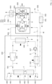
- FIG. 1 represents the architecture of the energy production system according to one embodiment of the invention.
- the process thus allows optimized integration of the absorption cycle in which the condensation of the first working fluid in the first condenser is optimized by the use of the cold produced by the absorption cycle.
- This arrangement is particularly useful for ensuring correct condensation in the first condenser, all the more so when the climatic conditions, in summer, do not provide a sufficiently low ambient air temperature.
- the upstream and downstream, the inlet, the outlet, at a given point are taken with reference to the direction of circulation of the fluid.
- fluidically connected or “in fluidic connection” is understood to mean when a line provides a connection through or in which a fluid circulates.
- a fluidically connected to B or “A fluidically connected to B” is synonymous with "A is in fluidic connection with B” and does not necessarily mean that there is no organ between A and B
- these expressions mean a fluid connection between two elements, this connection which may or may not be direct. This means that it is possible that between a first element and a second element which are fluidically connected, a path of a fluid exists through one or more conduits, possibly an additional organ.
- directly fluidly connected means a direct fluidic connection between two elements. This means that between a first element and a second element which are fluidically directly connected no other element is present, other than a conduit or several conduits.
- A is thermally connected to B” or “A is in thermal connection with B” we mean that thermal energy circulates between A and B with no fluidic connection.
- hot, cold, cooled, reheated we mean a relative temperature compared to another point in the system.
- a parameter “substantially equal/greater/less than” or “of the order of” a given value is meant that this parameter is equal/greater/less than the given value, to within plus or minus 10%, or even to plus or minus 5% of this value.
- the system according to the invention comprises an organic Rankine cycle 100 and an absorption cycle 200.
- the system includes an organic Rankine Cycle 100 (Organic Rankine Cycle, ORC) also hereinafter referred to as Rankine Cycle 100, which makes it possible in particular to produce mechanical power from a hot source at low or medium temperature.
- ORC Organic Rankine Cycle
- the Rankine 100 cycle makes it possible to recover thermal energy by transforming thermal energy into mechanical energy.
- thermal energy comes from the processing industry (metallurgy, chemistry, papermaking, etc.) with low-temperature thermal discharges, from transport with a thermal engine in which we have heat needs: automobile, boat, or concentrated solar power, or biomass or geothermal energy.
- the Rankine cycle 100 comprises an expander 105 and a first pump 107 arranged in series with a first evaporator 104 and a first condenser 106 and advantageously according to the invention a preheating device.
- the Rankine cycle 100 includes a first circulation loop 101 intended to receive a working fluid.
- the first circulation loop 101 ensures the fluid connection of the constituents of the Rankine cycle 100 so that the working fluid passes through them preferentially successively in the order if after, the preheating device, more precisely the first preheating exchanger 102 then the second preheating exchanger 103, the first evaporator 104, the expander 105, the first condenser 106 and the first pump 107, then again the preheating device.
- the circulation loop 101 is advantageously a closed circuit.
- the Rankine cycle 100 advantageously comprises a working fluid.
- the working fluid may be a pure fluid.
- the working fluid is a mixture of fluids, at least two fluids, or even more.
- the working fluid is preferably organic.
- the working fluid is for example the R1233 zd fluid.
- the Rankine cycle 100 comprises a preheating device.
- the preheating device comprises at least a first preheating exchanger 102.
- the preheating device comprises a second preheating exchanger 103.
- the first preheating exchanger 102 and possibly the second preheating exchanger 103 are heat exchangers arranged on the first circulation loop 101 of the Rankine cycle 100.
- the preheating device is configured to heat the working fluid up to the vaporization temperature, that is to say in other words up to the appearance of the first steam bubble.
- the working fluid enters the preheating device in the compressed liquid state and leaves at the start of the two-phase state (liquid-vapor).
- the preheating device is fluidly connected to the first pump 107 and to the first evaporator 104.
- the first circulation loop 101 comprises a fluid connection D arranged between the first pump 107 and the first heat exchanger 102 and allowing entry of the working fluid in the first preheating exchanger 102, preferably directly, from the outlet of the first pump 107.
- the first circulation loop 101 comprises a fluid connection E arranged between the first preheating exchanger 102 and the second preheating exchanger 103 and allowing the entry of the working fluid into the second preheating exchanger 103, preferably directly, from the outlet of the first preheating exchanger 102.
- the first circulation loop 101 comprises a fluid connection F arranged between the second preheating exchanger 103 and the first evaporator 104 and allowing the outlet of the working fluid outside the preheating device, preferably directly, towards the first evaporator 104.
- the preheating device comprises only the first preheating exchanger 102, it is this which is in fluidic connection with the first evaporator 104 to ensure, preferably directly , the entry of the working fluid into the first evaporator 104, from the outlet of the preheating device.
- the first preheating exchanger 102 is thermally coupled to the intermediate circuit 300 acting as a heat source.
- the second preheating exchanger 103 it is thermally coupled to a heat source.
- the heat source is preferably the first heat source 400 which may have already passed through the first evaporator 104.
- the Rankine cycle also includes a first evaporator 104.
- the first evaporator 104 is a heat exchanger arranged on the first circulation loop 101 of Rankine cycle 100.
- the first evaporator 104 is configured to completely evaporate the working fluid.
- the working fluid comes out slightly overheated so as not to send droplets of liquid to the expander 105.
- the first evaporator 104 is thermally coupled to a heat source 400.
- the first evaporator 104 includes an inlet and a heat source outlet 400 allowing the heat input necessary for the overheating of the working fluid.
- the temperature of the heat source 400 is less than 200°C.
- the first evaporator 104 is fluidly connected to the preheating device and to the expander 105.
- the first circulation loop 101 comprises a fluidic connection F arranged between the preheating device, more precisely the second preheating exchanger 103, and the first evaporator 104 allowing the entry of the working fluid into the first evaporator 104, preferably directly, from the preheating device, more precisely from the outlet of the second preheating exchanger 103.
- the first circulation loop 101 comprises a fluid connection A arranged between the first evaporator 104 and the expander 105 allowing the entry of the working fluid into the expander 105, preferably directly, from the outlet of the first evaporator 104.
- the inlet of the first evaporator 104 is fluidly connected to the outlet of the preheating device and the outlet of the first evaporator 104 is fluidly connected to the inlet of the expander 105.
- the Rankine cycle also includes an expander 105 such as for example a volumetric expansion machine or a turbine.
- This expander 105 allows the working fluid to be relaxed and mechanical energy to be produced from this relaxation.
- the working fluid enters the expander 105 as high pressure compressed vapor and exits the expander 105 as low pressure expanded vapor.
- this energy is recovered on a rotating shaft.
- This mechanical energy can then be recovered in electrical form at the level of an alternator located on said rotating shaft or a compressor or a pump allowing the use of mechanical energy directly.
- the expander 105 is for example derived from a conventional volumetric expansion machine from the refrigeration industry; other turbomachines or specific volumetric machines will be more efficient.
- the expander 103 is fluidly connected to the first evaporator 104 and the first condenser 106.
- the first circulation loop 101 comprises a fluid connection B arranged between the expander 105 and the first condenser 106, allowing the entry of the working fluid into the first condenser 106, preferably directly, from the outlet of the expander 105.
- the inlet of the expander 105 is fluidly connected to the outlet of the first evaporator 104 and the outlet of the expander 105 is fluidly connected to the entry of the first condenser 106.
- the Rankine cycle 100 also includes a first condenser 106.
- the first condenser 106 is a heat exchanger arranged on the first circulation loop 101 of the Rankine cycle 100.
- the first condenser 106 is configured to cool the working fluid.
- the working fluid enters the condenser 106 in the state of low pressure expanded vapor and leaves in the liquid state, preferably subcooled to avoid the risk of cavitation in the pump.
- the first condenser 106 is thermally coupled to a cold source 501 making it possible to cool the working fluid to condense it, or even sub-cool it. During this cooling, the dew point temperature is reached. Cooling is therefore accompanied by the phenomenon of condensation.
- the cold source 501 advantageously comes from the absorption cycle described below. The cold source 501 brings the cold produced by the evaporator of the absorption cycle to the first condenser 106 of the Rankin cycle e100.
- the first condenser 106 is fluidly connected to the expander 105 and to the first pump 107.
- the first circulation loop 101 comprises a fluid connection C arranged between the first condenser 106 and the first pump 107 allowing the entry of the fluid from work in the first pump 107, preferably directly, from the outlet of the first condenser 106.
- the inlet of the condenser 106 is fluidly connected to the outlet of the expander 105 and the outlet of the first condenser 106 is fluidly connected to the entry of the first pump 107.
- the Rankine cycle 100 also includes a first pump 107. Preferably, it allows the working fluid to be compressed.
- the working fluid enters the first pump 107 in the liquid state and exits in the high pressure compressed liquid state.
- the first pump 107 requires a supply of energy, conventionally in the form of electricity to set the working fluid in motion.
- the first pump 107 is fluidly connected to the first condenser 106 and to the preheating device, more preferably to the first preheating exchanger 102.
- the first circulation loop 101 comprises a fluidic connection D arranged between the first pump 107 and the preheating device and more precisely with the first preheating exchanger 102 allowing the entry of the working fluid into the preheating device, preferably directly, from the outlet of the first pump 107.
- the inlet of the first pump 107 is fluidly connected to the outlet of the first condenser 106 and the outlet of the first pump 107 is fluidly connected to the inlet of the preheating device, more precisely the inlet of the first preheating exchanger 102.
- the first heat source 400 enters the first evaporator 104 to provide energy ensuring the vaporization of the working fluid.
- the first heat source 400 forms at least partially and preferably completely the heat source supplying the second preheating exchanger 103.
- the heat source 400 enters the first evaporator 104 at a temperature of the order of 200°C and leaves the second preheating exchanger 103 at a temperature of around 90°C.
- the system according to the invention also comprises an absorption cycle 200.
- An absorption cycle uses refrigerant/sorbent pairs with strong affinities to replace the vapor compression of traditional heat pump type machines.
- This solution has low electrical consumption, the main energy coming from the thermal source, making it possible to limit the operating cost in the case of the valorization of a low-cost energy source such as gas for example or free (such as solar energy or heat rejection for example).
- the absorption cycle works thanks to a working solution.
- This type of absorption cycle works thanks to the ability of certain liquids to absorb (exothermic reaction) and desorb (endothermic reaction) a vapor. It also uses the fact that the solubility of this vapor in the liquid depends on temperature and pressure.
- an absorption cycle uses as a working solution comprising a binary mixture, one of the components of which is more volatile than the other, and constitutes the refrigerant.
- the H 2 O/LiBr couple can optionally also be used.
- An absorption cycle 200 comprises four main exchangers (generator 203, absorber 202, condenser 204 and evaporator 205), and advantageously from one to three secondary exchangers.
- the role of the three secondary exchangers is to improve the performance of the cycle such as: a rectifier, an economizer, a subcooler.
- the absorption cycle comprises at least one regulator 206, and at least one solution loop comprising a solution pump 208 and an expansion valve 207.
- This type of cycle operates according to three temperature levels: a temperature level low corresponding to the production of cold at the evaporator 205, an intermediate temperature level corresponding to the condensation temperature of the refrigerant, but also to that of absorption of the refrigerant by the absorbent and a high temperature level corresponding to the driving temperature of generator 203.
- the absorption cycle 200 comprises a second circulation loop of 201 configured to ensure the fluidic connection of the different components of the cycle to absorption.
- the second circulation loop 201 is a closed circuit intended to receive the working solution.
- An absorption cycle operates partly at high pressure between the pump 208 upstream of the generator 203 and the expander 206, downstream of the condenser 204, and partly at low pressure between the expander 206, downstream of the condenser 204 and the pump 208 upstream of the generator 203.
- thermodynamic cycle is feasible due to the vapor pressure difference between the absorbent and the refrigerant which is variable depending on the temperature and pressure. This variability allows for a difference in concentration between the poor solution and the rich solution described below.
- the advantage of this absorption cycle is that mechanical compression is replaced by thermochemical compression which uses heat, that is to say a degraded primary energy source. The only primary energy input required is at the solution pump 208, but its work is approximately 96 times less than the work that the steam compressor must provide for similar operating conditions.
- the absorption cycle comprises a refrigerant/absorbent working solution comprising, according to one possibility, the Ammonia/Water couple (NH3/H2O).
- the concentrations of the working solution and the absorbent in the working solution are adapted to the pressure and temperature of the air treatment and lower than the crystallization concentration of the solution.
- the working solution comprises ionic liquids.
- This NH3/H2O couple can be used for air conditioning applications, but also refrigeration and there is no crystallization possible over the pressure and temperature operating ranges.
- the vapor pressure difference between the absorbent and the refrigerant is small. There are therefore traces of water carried with the ammonia vapor at the outlet of generator 203, sometimes requiring the presence of a rectifier.
- the working solution is called rich, because the concentration of refrigerant is greater than in the so-called lean working solution.
- the generator 203 is fluidly connected to the second condenser 204 by a fluid connection G allowing the refrigerant vapor to exit from the generator 203 towards the second condenser 204.
- the generator 203 also includes an inlet and a second source outlet heat 405 allowing the heat supply necessary for the vaporization of the refrigerant.
- the absorption cycle 200 can include a rectifier placed between the generator 203 and the condenser 204, more precisely on the fluid connection G.
- the rectifier makes it possible to remove by condensation the traces of water carried with the fluid of the device.
- the second condenser 204 also includes a cooling source.
- the phase change of the refrigerant from the vapor state to the liquid state is accompanied by a release of heat.
- the cooling source of the condenser 204 is formed by the intermediate fluid of the intermediate circuit 300. The release of heat produced by the condenser 204 is transmitted to the intermediate fluid circulating in the intermediate circuit 300.
- the absorption cycle can comprise a sub-cooler arranged between the condenser 204 and the evaporator 205, and between the evaporator 205 and the absorber 202, more precisely on the fluidic connection H and on a fluidic connection I at the outlet of the evaporator.
- the subcooler makes it possible to subcool the refrigerant at the inlet of the evaporator 205 and to preheat the refrigerant to the vapor state at the outlet of the evaporator 205.
- This exchanger therefore makes it possible to reduce the size of the condenser 204 and the evaporator 205 and thus significantly improve the performance of the machine. The relevance of this component depends on the operating temperatures, the size of the machine and the cost of the exchangers.
- the system comprises an intermediate circuit 300 capable of receiving an intermediate fluid.
- the intermediate circuit 300 is a fluid circulation loop preferably in a closed circuit.
- the intermediate circuit 300 is configured to ensure the thermal connection between the ORC cycle 100 and the absorption cycle 200.
- the intermediate circuit 300 is intended to supply the ORC cycle 100 with heat rejected by the absorption cycle 200.
- the heat rejected by the absorption cycle 200 by the absorber 202 and/or the condenser 204 is transmitted to the ORC cycle 100 by the intermediate circuit 300.
- the heat is advantageously transmitted to the preheating device of the ORC cycle 100 and in particular to the first preheating exchanger 102.
- the intermediate circuit 300 ensures the fluid circulation of the intermediate fluid successively in the absorber 202 and/or the condenser 204 and in the preheating device, more precisely in the first preheating exchanger 102.
- the absorber 202 and the condenser 204 are arranged on the intermediate circuit 300 successively, that is to say in series, so that the intermediate fluid circulates in the absorber 202 to recover the heat rejected by it then circulates in the condenser 204 in which the intermediate fluid also recovers the heat rejected by it.
- the intermediate circuit can include the condenser 204 and absorber 202 arranged in parallel.
- the condenser 204 and absorber 202 arranged in parallel.
- the intermediate circuit 300 comprises branches configured to allow the circulation of the intermediate fluid without circulating in the absorber 202 or the condenser 204.
- the intermediate circuit comprises the circulation in the absorber 202 or in its first branch according to whether or not the heat from the absorber must be recovered depending on the needs and temperatures of predefined points in the system, then circulation in the condenser 204 or in its second bypass depending on whether or not the heat from the absorber must be recovered or not according to the needs and temperatures of predefined points of the system.
- the intermediate fluid enters the absorber 202 at a temperature of around 35°C and leaves it at a temperature of around 58°.
- the intermediate fluid enters the condenser 204 at this temperature and leaves at a temperature of around 75°.
- the intermediate fluid circulates in the preheating device of the ORC cycle 100, in particular in the first preheating exchanger 102. Depending on the needs of the ORC cycle, the intermediate fluid transmits more or less heat to the ORC cycle 100.
- the intermediate circuit 300 comprises a first intermediate exchanger 301 arranged on the intermediate circuit 300 between the ORC cycle 100 and the absorption cycle 200, that is to say between the preheating device and the absorber 202 or the condenser 204, if the absorber 202 is not arranged on the intermediate circuit 300.
- the first intermediate exchanger 301 is arranged downstream of the preheating device and more precisely of the first preheating exchanger 102.
- the first intermediate exchanger 301 is arranged upstream of the absorber 202, or of the condenser 204 if the absorber 2022 is not arranged on the intermediate circuit 300.
- the first intermediate exchanger 301 makes it possible to use the residual heat of the intermediate fluid at the outlet of the device preheating.
- the first intermediate exchanger 301 finishes this thermal recovery.
- a recovery fluid circulates in the first intermediate exchanger 301.
- the recovery fluid can be a cooling source such as an air flow coming from a cooling tower or from a unit heater.
- the recovery fluid is intended to supply a domestic hot water network. This arrangement makes it possible both to use all of the thermal energy rejected by the absorption cycle 200 and to ensure that the fluid intermediate can once again play its function as a cold source near the absorber 202 and/or the condenser 204.
- the intermediate fluid is chosen from water or oil.
- the intermediate circuit 300 comprises a fluid connection L arranged between the condenser 204 and the preheating device, more precisely the first preheating exchanger 102 to ensure the circulation of the intermediate fluid between the outlet of the condenser 204, preferably directly, towards the inlet of the preheating device, more precisely the first preheating exchanger 102.
- the intermediate circuit 300 comprises a fluid connection M arranged between the preheating device, more precisely the first preheating exchanger 102 and advantageously the first intermediate exchanger 301 to ensure the circulation of the fluid intermediate between the preheating device outlet, more precisely the first preheating exchanger 102, towards, preferably directly, the inlet of the first intermediate exchanger 301.
- the intermediate circuit 300 comprises a fluid connection N arranged between the first intermediate exchanger 301 and the absorber 202 to ensure the circulation of the intermediate fluid from the outlet of the first intermediate exchanger 301 towards, preferably directly, the inlet of the absorber 202.
- the intermediate circuit comprises a fluid connection O arranged between the absorber 202 and the condenser 204 to ensure the circulation of the intermediate fluid from the outlet of the absorber 200 towards, preferably directly, the inlet of the condenser 204.
- the system comprises an additional thermal connection between the ORC cycle 100 and the absorption cycle 200.
- This additional thermal connection is in addition to the thermal connection provided by the intermediate circuit 300.
- the system comprises a thermal connection between the second evaporator 205 of the absorption cycle 200 and the first condenser 106 of the ORC cycle 100.
- the thermal connection is advantageously ensured by a cold source 501 coming from the second evaporator 205 of the absorption cycle 200 towards the first condenser 106 of the ORC cycle. This arrangement is particularly useful for ensuring a temperature of cold source 501 at the first condenser 106 that is sufficiently low whatever the climatic conditions.
- the condenser 106 of the ORC cycle requires cooling to condense the vapor leaving the expander 105.
- the absorption cycle 200 therefore makes it possible to provide additional cooling thanks to thermal coupling.
- the second evaporator 205 of the absorption cycle 200 is used to cool the cold source 501 of the first condenser 106 of the ORC cycle 100.
- a source to be cooled 500 circulates beforehand in the second evaporator 205 to ensure the evaporation of the working solution of the absorption cycle 200.
- the heat source 500 transfers thermal energy to the absorption cycle 200 and cools from the second evaporator 205 in the form of a cold source 501.
- the cold source 501 supplies the first condenser 106 to allow optimal condensation of the working fluid.
- the system comprises a fluid connection P arranged to penetrate into the second evaporator 205 and ensure the entry of the first source to be cooled 500 into the second evaporator 205.
- the system comprises a fluid connection Q arranged between the second evaporator 205 and the first condenser 106 to ensure the circulation of the cold source 501 from the outlet of the evaporator 205, preferably directly, towards the inlet of the condenser 106.
- the system comprises a fluid connection R ensuring the outlet of the cold source 501 outside the condenser 106.
- the condenser 106 may include a complementary cold source.
- the source to be cooled 500 comes from a cooling circuit conventionally used for cooling an ORC cycle.
- the source to be cooled 500 is chosen from an air flow coming from an air heater or a cooling tower.
- the source to be cooled 500 and the recovery fluid 502 come from the same cooling circuit supplied by an air heater or a cooling tower.
- the source to be cooled 500 enters the second evaporator 205 at a temperature of around 25°C.
- the source to be cooled 500 emerges in the form of a cold source 501 at a temperature of around 20°C to enter the first condenser 106.
- the cold source 501 emerges from the condenser 106 at a temperature of around 50°C .
- the invention comprises an additional thermal connection between the ORC cycle and the absorption cycle 200.
- the additional thermal connection is intended to ensure the thermal connection between the generator 203 of the absorption cycle 200 and at least the second evaporator 104 of the ORC cycle 100
- the additional thermal connection is configured to use as the second heat source 405 of the generator 203 of the absorption cycle 200, the first heat source 400 supplying the first evaporator 104 of the ORC cycle 100.
- the first heat source 400 supplying the first evaporator 104 can come from renewable energy such as geothermal, solar, or waste energy. such as residual thermal energy from industrial processes, or even fossil energy.
- the first hot source 400 enters the first evaporator 104 at a temperature between 90° and 200°C.
- the hot source 400 emerges from the first evaporator 104 and possibly passes through the preheating device and more precisely the second preheating exchanger 103.
- the heat source 400 emerges, for example, at a temperature of the order of 90°C.
- the system according to the invention advantageously comprises at least one tap 401, 402, 403 ensuring the bypass of a part of the first heat source 400 for the benefit of the generator 203.
- the system advantageously comprises a control module ensuring the operation of the at least one tap 401, 402, 403 depending on the temperatures of the hot source 400 and the needs of the generator 203.
- the system comprises three taps 401, 402, 403.
- the system advantageously comprises a first tap 401 arranged in upstream of the inlet of the first hot source 400 in the first evaporator 104.
- the system advantageously comprises a second tap 402 arranged downstream of the outlet of the first hot source 400 of the first evaporator 104 and upstream of the heating device more precisely of the second preheating exchanger 103.
- the system advantageously comprises a third tap 402 arranged downstream of the outlet of the hot source of the second preheating exchanger 103.
- the first hot source 400 coming from one of the connections 401, 402, 403 circulates directly in the generator 203, the first hot source 400 and the second hot source 405 are identical.
- the system comprises a second intermediate exchanger 404 ensuring the thermal transfer of the first hot source 400 for the benefit of a second hot source 405.
- the second hot source 405 circulates in a closed circuit between the second intermediate exchanger 404 and the generator 203.
Abstract
L'invention concerne un système de production d'énergie comprenant : - Un cycle de Rankine organique(100) (ORC) comprenant une première boucle de circulation (101 ) d'un premier fluide de travail comprenant un dispositif de préchauffage, un premier évaporateur (104), un expanseur (105), un premier condenseur (106 )et une première pompe (107), - Un cycle à absorption (200) comprenant une deuxième boucle de circulation (200) d'une solution de travail comprenant un absorbeur(200 de), un générateur (203), un deuxième condenseur (204), une deuxième pompe (208) et un deuxième évaporateur (205), caractérisé en ce que le système comprend un circuit intermédiaire (300) apte à recevoir un fluide intermédiaire et assurant la connexion thermique du cycle ORC (100) et du cycle à absorption (200) et sur lequel sont agencés le deuxième condenseur (204), l'absorbeur (202) et le dispositif de préchauffage.Elle trouvera plus particulièrement son application dans un objectif de récupération d'énergie et d'optimisation des rendements.The invention relates to an energy production system comprising: - An organic Rankine cycle (100) (ORC) comprising a first circulation loop (101) of a first working fluid comprising a preheating device, a first evaporator (104), an expander (105), a first condenser (106) and a first pump (107), - An absorption cycle (200) comprising a second circulation loop (200) of a working solution comprising an absorber (200), a generator (203), a second condenser (204), a second pump (208) and a second evaporator (205), characterized in that the system comprises an intermediate circuit (300) capable of receiving a fluid intermediate and ensuring the thermal connection of the ORC cycle (100) and the absorption cycle (200) and on which the second condenser (204), the absorber (202) and the preheating device are arranged. It will find its application more particularly with the aim of recovering energy and optimizing yields.
Description
La présente invention concerne un système de production d'énergie associant un cycle de Rankine organique et un cycle à absorption. L'invention trouvera plus particulièrement son application dans un objectif de récupération d'énergie et d'optimisation des rendements de production électrique d'un cycle ORC.The present invention relates to an energy production system combining an organic Rankine cycle and an absorption cycle. The invention will more particularly find its application with the objective of energy recovery and optimization of the electrical production yields of an ORC cycle.
Les systèmes de production d'électricité par cycles thermodynamiques sont largement connus. Notamment, les cycles Rankine organique (ORC) qui valorisent une source de chaleur, couramment une source de chaleur d'une température comprise entre 90°C et 200°C.Systems for producing electricity by thermodynamic cycles are widely known. In particular, organic Rankine cycles (ORC) which exploit a heat source, commonly a heat source with a temperature between 90°C and 200°C.
Ces systèmes ont besoin d'un refroidissement pour condenser la vapeur sortant de l'organe de détente (turbine). Ce refroidissement est généralement réalisé par un aérotherme ou une tour de refroidissement.These systems need cooling to condense the steam leaving the expansion unit (turbine). This cooling is generally carried out by an air heater or a cooling tower.
En été, lorsque l'ambiance est chaude, par exemple au-dessus de 35°C, la condensation en sortie de la turbine aura lieu à des hautes températures, par exemple jusqu'à 60°C, ce qui peut entrainer une perte significative de la production d'électricité.In summer, when the environment is hot, for example above 35°C, condensation at the turbine outlet will take place at high temperatures, for example up to 60°C, which can cause a significant loss. of electricity production.
On connait des systèmes qui intègrent un cycle de Rankine organique et un cycle à absorption comme notamment le document
Ces solutions bien que permettant d'optimiser le refroidissement du cycle de Rankine génèrent un rejet de chaleur par la machine à absorption qui se fait dans l'air ambiant présentant ainsi sensiblement les mêmes problématiques. Il existe donc le besoin de proposer un système de production d'énergie dont le rendement est optimisé.These solutions, although making it possible to optimize the cooling of the Rankine cycle, generate a rejection of heat by the absorption machine which takes place in the ambient air, thus presenting substantially the same problems. There is therefore a need to propose an energy production system whose performance is optimized.
Pour atteindre cet objectif, selon un mode de réalisation on prévoit un Système de production d'énergie comprenant : -un cycle de Rankine organique (ORC) comprenant une première boucle de circulation d'un premier fluide de travail comprenant un dispositif de préchauffage, un premier évaporateur, un expanseur, un premier condenseur et une première pompe, - un cycle à absorption comprenant une deuxième boucle de circulation d'une solution de travail comprenant un absorbeur, un générateur, un deuxième condenseur, une deuxième pompe et un deuxième évaporateur, caractérisé en ce que le système comprend un circuit intermédiaire apte à recevoir un fluide intermédiaire et assurant la connexion thermique du cycle ORC et du cycle à absorption et sur lequel sont agencés le deuxième condenseur et/ou l'absorbeur et le dispositif de préchauffage.To achieve this objective, according to one embodiment, an energy production system is provided comprising: -an organic Rankine cycle (ORC) comprising a first circulation loop of a first working fluid comprising a preheating device, a first evaporator, an expander, a first condenser and a first pump, - an absorption cycle comprising a second circulation loop of a working solution comprising an absorber, a generator, a second condenser, a second pump and a second evaporator, characterized in that the system comprises an intermediate circuit capable of receiving an intermediate fluid and ensuring the thermal connection of the ORC cycle and the absorption cycle and on which the second condenser and/or absorber and preheating device.
Le circuit intermédiaire permet de récupérer le rejet de chaleur en sortie des composants absorbeur et condenseur du cycle à absorption pour préchauffer le premier fluide de travail du cycle ORC, cela permet également d'assurer un refroidissement satisfaisant des composants absorbeur et condenseur du cycle à absorption quelques soit les conditions climatiques pour permettre un fonctionnement dans les meilleures conditions de rendement.The intermediate circuit makes it possible to recover the heat rejection at the outlet of the absorber and condenser components of the absorption cycle to preheat the first working fluid of the ORC cycle, this also ensures satisfactory cooling of the absorber and condenser components of the absorption cycle whatever the climatic conditions to allow operation in the best performance conditions.
Selon un autre aspect ; l'invention concerne un procédé de production d'énergie par un système tel que décrit ci-dessus comprenant : - la production d'énergie électrique par l'expanseur du cycle ORC, - un rejet de chaleur par l'absorbeur et le deuxième condenseur du cycle à absorption, caractérisé en ce que la chaleur rejetée par l'absorbeur et/ou le deuxième condenseur du cycle à absorption est transmise au dispositif de préchauffage du cycle ORC par le circuit intermédiaire.According to another aspect; the invention relates to a method of producing energy by a system as described above comprising: - the production of electrical energy by the ORC cycle expander, - heat rejection by the absorber and the second condenser of the absorption cycle, characterized in that the heat rejected by the absorber and/or the second condenser of the absorption cycle is transmitted to the preheating device of the ORC cycle via the intermediate circuit.
Le procédé permet ainsi d'utiliser les rejets de chaleur de la machine à absorption pour alimenter le cycle ORC.The process thus makes it possible to use heat rejects from the absorption machine to power the ORC cycle.
Les buts, objets, ainsi que les caractéristiques et avantages de l'invention ressortiront mieux de la description détaillée d'un mode de réalisation de cette dernière qui est illustré par les dessins d'accompagnement suivants dans lesquels :
La
There
Les dessins sont donnés à titre d'exemples et ne sont pas limitatifs de l'invention. Ils constituent des représentations schématiques de principe destinées à faciliter la compréhension de l'invention et ne sont pas nécessairement à l'échelle des applications pratiques.The drawings are given as examples and do not limit the invention. They constitute schematic representations of principle intended to facilitate the understanding of the invention and are not necessarily on the scale of practical applications.
Avant d'entamer une revue détaillée de modes de réalisation de l'invention, sont énoncées ci-après des caractéristiques optionnelles qui peuvent éventuellement être utilisées en association ou alternativement :
- Selon un exemple, le circuit intermédiaire 300 comprend un premier échangeur thermique intermédiaire 300 assurant un transfert thermique entre le circuit intermédiaire 300 et un fluide de
récupération 502. Selon le fonctionnement du cycle ORC, la récupération du rejet de chaleur des composants absorbeur et/ou condenseur du cycle à absorption pour préchauffer le premier fluide de travail du cycle ORC peut être totale ou partielle, dans ce dernier cas, le premier échangeur thermique intermédiaire permet de compléter le refroidissement du fluide intermédiaire circulant dans le circuit intermédiaire avant de récupérer à nouveau de la chaleur dans l'absorbeur et/ou le condenseur, - Selon un exemple, le fluide de
récupération 502 est issu d'un aérotherme ou d'une tour de refroidissement, - Alternativement, le fluide de
récupération 502 est destiné à alimenter un circuit d'eau chaude sanitaire, - Selon un exemple, le
deuxième évaporateur 205 et lepremier condenseur 106 sont connectés thermiquement de sorte que ledeuxième évaporateur 205 transmette sa production de froid aupremier condenseur 106 assurant la condensation du premier fluide de travail dans lepremier condenseur 106, - Selon un exemple, le système comprend une source froide 501 assurant la connexion thermique du
deuxième évaporateur 205 du cycle àabsorption 200 vers lepremier condenseur 106 du cycle ORC 100, - Selon un exemple, le cycle à
absorption 200 comprend une source à refroidir 500 alimentant ledeuxième évaporateur 205, et une source froide 500 en sortie dudeuxième évaporateur 205 destinée à alimenter lepremier condenseur 106, - Alternativement, le
premier condenseur 106 et ledeuxième évaporateur 205 sont mutualisés dans un échangeur thermique commun entre le cycle ORC 100 et le cycle àabsorption 200. On entend par là que la fonction de premier condenseur et la fonction de deuxième évaporateur sont réalisées par un échangeur thermique commun au cycle ORC et au cycle à absorption, le système comprend un échangeur thermique unique agissant comme condenseur du cycle ORC et comme évaporateur du cycle à absorption. - Selon un exemple, le cycle ORC 200 comprend une première source de
chaleur 400 alimentant lepremier évaporateur 104 et dans lequel le cycle àabsorption 200 comprend une deuxième source dechaleur 405 alimentant legénérateur 203, la première source dechaleur 400 et la deuxième source dechaleur 405 étant connectées thermiquement, - Selon un exemple, le système comprend un deuxième échangeur thermique intermédiaire 404 configuré pour assurer la connexion thermique de la première source de
chaleur 400 et la deuxième source dechaleur 405, - Avantageusement, le procédé comprend le transfert thermique de la production de froid du
deuxième évaporateur 205 du cycle àabsorption 200 au profit dupremier condenseur 106 du cycle ORC 100.
- According to one example, the
intermediate circuit 300 comprises a firstintermediate heat exchanger 300 ensuring heat transfer between theintermediate circuit 300 and arecovery fluid 502. Depending on the operation of the ORC cycle, the recovery of the heat rejection from the absorber components and/or condenser of the absorption cycle to preheat the first working fluid of the ORC cycle can be total or partial, in the latter case, the first exchanger intermediate thermal makes it possible to complete the cooling of the intermediate fluid circulating in the intermediate circuit before recovering heat again in the absorber and/or the condenser, - According to one example, the
recovery fluid 502 comes from a unit heater or a cooling tower, - Alternatively, the
recovery fluid 502 is intended to supply a domestic hot water circuit, - According to one example, the
second evaporator 205 and thefirst condenser 106 are thermally connected so that thesecond evaporator 205 transmits its cold production to thefirst condenser 106 ensuring the condensation of the first working fluid in thefirst condenser 106, - According to one example, the system comprises a
cold source 501 ensuring the thermal connection of thesecond evaporator 205 of theabsorption cycle 200 to thefirst condenser 106 of theORC cycle 100, - According to one example, the
absorption cycle 200 comprises a source to be cooled 500 supplying thesecond evaporator 205, and a cold source 500 at the outlet of thesecond evaporator 205 intended to supply thefirst condenser 106, - Alternatively, the
first condenser 106 and thesecond evaporator 205 are shared in a common heat exchanger between theORC cycle 100 and theabsorption cycle 200. By this we mean that the function of first condenser and the function of second evaporator are carried out by a heat exchanger common to the ORC cycle and the absorption cycle, the system includes a single heat exchanger acting as a condenser of the ORC cycle and as an evaporator of the absorption cycle. - According to one example, the
ORC cycle 200 comprises afirst heat source 400 supplying thefirst evaporator 104 and in which theabsorption cycle 200 comprises asecond heat source 405 supplying thegenerator 203, thefirst heat source 400 and the second source ofheat 405 being thermally connected, - According to one example, the system comprises a second
intermediate heat exchanger 404 configured to ensure the thermal connection of thefirst heat source 400 and thesecond heat source 405, - Advantageously, the method comprises the thermal transfer of the cold production of the
second evaporator 205 of theabsorption cycle 200 for the benefit of thefirst condenser 106 of theORC cycle 100.
Le procédé permet ainsi une intégration optimisée du cycle à absorption dans laquelle la condensation du premier fluide de travail dans le premier condenseur est optimisée par l'utilisation du froid produit par le cycle à absorption. Cette disposition est particulièrement utile pour assurer une condensation correcte dans le premier condenseur et cela d'autant plus quand les conditions climatiques, en été, ne fournissent pas une température d'air ambiant suffisamment basse.The process thus allows optimized integration of the absorption cycle in which the condensation of the first working fluid in the first condenser is optimized by the use of the cold produced by the absorption cycle. This arrangement is particularly useful for ensuring correct condensation in the first condenser, all the more so when the climatic conditions, in summer, do not provide a sufficiently low ambient air temperature.
L'amont et l'aval, l'entrée, la sortie, en un point donné sont pris en référence au sens de circulation du fluide.The upstream and downstream, the inlet, the outlet, at a given point are taken with reference to the direction of circulation of the fluid.
On entend par « connecté fluidiquement » ou « en connexion fluidique », lorsqu'une ligne assure une connexion par ou dans laquelle circule un fluide.The term “fluidically connected” or “in fluidic connection” is understood to mean when a line provides a connection through or in which a fluid circulates.
L'expression « A fluidiquement connecté à B » ou encore « A fluidiquement raccordé à B » est synonyme de « A est en connexion fluidique avec B » et ne signifie pas nécessairement qu'il n'existe pas d'organe entre A et B. Ainsi, ces expressions s'entendent d'une connexion fluidique entre deux éléments, cette connexion pouvant ou non être directe. Cela signifie qu'il est possible qu'entre un premier élément et un deuxième élément qui sont fluidiquement connectés, un parcours d'un fluide existe par un ou des conduits, éventuellement un organe supplémentaire.The expression "A fluidically connected to B" or "A fluidically connected to B" is synonymous with "A is in fluidic connection with B" and does not necessarily mean that there is no organ between A and B Thus, these expressions mean a fluid connection between two elements, this connection which may or may not be direct. This means that it is possible that between a first element and a second element which are fluidically connected, a path of a fluid exists through one or more conduits, possibly an additional organ.
Les expressions «agencée sur» ou «sur» sont synonymes de « raccordé fluidiquement à ».The expressions “arranged on” or “on” are synonymous with “fluidically connected to”.
À l'inverse, le terme «fluidiquement connecté directement» s'entend d'une connexion fluidique directe entre deux éléments. Cela signifie qu'entre un premier élément et un deuxième élément qui sont fluidiquement connectés directement aucun autre élément n'est présent, autre qu'un conduit ou plusieurs conduits.Conversely, the term “directly fluidly connected” means a direct fluidic connection between two elements. This means that between a first element and a second element which are fluidically directly connected no other element is present, other than a conduit or several conduits.
On entend par « A est connecté thermiquement à B» ou « A est en connexion thermique avec B» que de l'énergie thermique circule entre A et B avec un sans connexion fluidique.By “A is thermally connected to B” or “A is in thermal connection with B” we mean that thermal energy circulates between A and B with no fluidic connection.
On entend par chaud, froid, refroidi, réchauffé, une température relative par rapport à un autre point du système.By hot, cold, cooled, reheated, we mean a relative temperature compared to another point in the system.
On entend par un paramètre "sensiblement égal/supérieur/inférieur à" ou "de l'ordre de" une valeur donnée, que ce paramètre est égal/supérieur/inférieur à la valeur donnée, à plus ou moins 10 % près, voire à plus ou moins 5 % près, de cette valeur.By a parameter "substantially equal/greater/less than" or "of the order of" a given value is meant that this parameter is equal/greater/less than the given value, to within plus or minus 10%, or even to plus or minus 5% of this value.
L'usage de l'article indéfini " un " ou " une " pour un élément ou une étape n'exclut pas, sauf mention contraire, la présence d'une pluralité de tels éléments ou étapes.The use of the indefinite article “un” or “une” for an element or a step does not exclude, unless otherwise stated, the presence of a plurality of such elements or steps.
Les termes "premier", "deuxième" et "troisième", etc. sont utilisés simplement comme des étiquettes, et ne sont pas destinés à imposer des exigences numériques sur leurs objets.The terms "first", "second" and "third", etc. are used simply as labels, and are not intended to impose numerical requirements on their objects.
Le système selon l'invention comprend un cycle organique de Rankine 100 et un cycle à absorption 200.The system according to the invention comprises an organic Rankine
Le système comprend un cycle organique de Rankine 100 (Organic Rankine Cycle, ORC, en anglais) également dénommé dans la suite cycle de Rankine 100, qui permet notamment de produire une puissance mécanique à partir d'une source chaude à basse ou moyenne température. Le cycle de Rankine 100 permet de valoriser l'énergie thermique en transformant l'énergie thermique en énergie mécanique. À titre d'exemple, l'énergie thermique est issue de l'industrie de transformation (métallurgie, chimie, papeterie...) avec les rejets thermiques à basse température, du transport avec moteur thermique dans lequel on a des besoins de chaleur : automobile, bateau, ou du solaire à concentration, ou de la biomasse ou de la géothermie.The system includes an organic Rankine Cycle 100 (Organic Rankine Cycle, ORC) also hereinafter referred to as Rankine Cycle 100, which makes it possible in particular to produce mechanical power from a hot source at low or medium temperature. The Rankine 100 cycle makes it possible to recover thermal energy by transforming thermal energy into mechanical energy. For example, thermal energy comes from the processing industry (metallurgy, chemistry, papermaking, etc.) with low-temperature thermal discharges, from transport with a thermal engine in which we have heat needs: automobile, boat, or concentrated solar power, or biomass or geothermal energy.
Selon un mode de réalisation de l'invention, le cycle de Rankine 100 comprend un expanseur 105 et une première pompe 107 agencés en série avec un premier évaporateur 104 et un premier condenseur 106 et avantageusement selon l'invention un dispositif de préchauffage. Le cycle de Rankine 100 comprend une première boucle de circulation 101 destinée à recevoir un fluide de travail. Avantageusement, la première boucle de circulation 101 assure la connexion fluidique des constituants du cycle de Rankine 100 de sorte que le fluide de travail les traverse préférentiellement successivement dans l'ordre si après, le dispositif de préchauffage, plus précisément le premier échangeur de préchauffage 102 puis le deuxième échangeur de préchauffage 103, le premier évaporateur 104, l'expanseur 105, le premier condenseur 106 et la première pompe 107, puis à nouveau le dispositif de préchauffage. La boucle de circulation 101 est avantageusement un circuit fermé.According to one embodiment of the invention, the
Le cycle de Rankine 100 comprend avantageusement un fluide de travail. Le fluide de travail peut être un fluide pur. Selon un mode de réalisation, le fluide de travail est un mélange de fluides, au moins deux fluides, voire plus. Le fluide de travail est de préférence organique. Le fluide de travail est par exemple le fluide R1233 zd.The
Selon un aspect de l'invention, le cycle de Rankine 100 comprend un dispositif de préchauffage. Selon une possibilité, le dispositif de préchauffage comprend au moins un premier échangeur de préchauffage 102. Préférentiellement, le dispositif de préchauffage comprend un deuxième échangeur de préchauffage 103. Le premier échangeur de préchauffage 102 et éventuellement le deuxième échangeur de préchauffage 103 sont des échangeurs thermiques agencés sur la première boucle de circulation 101 du cycle de Rankine 100. Le dispositif de préchauffage est configuré pour chauffer le fluide de travail jusqu'à la température de vaporisation c'est-à-dire en d'autres termes jusqu'à l'apparition de la première bulle de vapeur. Le fluide de travail entre dans le dispositif de préchauffage à l'état liquide comprimé et ressort en début d'état diphasique (liquide-vapeur).According to one aspect of the invention, the
Avantageusement, le dispositif de préchauffage est connecté fluidiquement à la première pompe 107 et au premier évaporateur 104. Préférentiellement, la première boucle de circulation 101 comprend une connexion fluidique D agencée entre la première pompe 107 et le premier échangeur thermique 102 et permettant l'entrée du fluide de travail dans le premier échangeur de préchauffage 102, préférentiellement directement, depuis la sortie de la première pompe 107.Advantageously, the preheating device is fluidly connected to the
Selon le mode de réalisation illustré en
Avantageusement, selon l'invention, le premier échangeur de préchauffage 102 est thermiquement couplé au circuit intermédiaire 300 jouant le rôle de source de chaleur.Advantageously, according to the invention, the
Dans le mode de réalisation comprenant le deuxième échangeur de préchauffage 103, celui-ci est thermiquement couplé à une source de chaleur. Selon une possibilité préférée, la source de chaleur est préférentiellement la première source de chaleur 400 qui peut avoir déjà traversée le premier évaporateur 104.In the embodiment comprising the
Le cycle de Rankine comprend également un premier évaporateur 104. Le premier évaporateur 104 est un échangeur thermique agencé sur la première boucle de circulation 101 de cycle de Rankine 100. Le premier évaporateur 104 est configuré pour évaporer complètement le fluide de travail. Préférentiellement, le fluide de travail ressort légèrement surchauffé de sorte à ne pas envoyer à l'expanseur 105 des gouttelettes de liquide.The Rankine cycle also includes a
Le premier évaporateur 104 est thermiquement couplé à une source de chaleur 400. Le premier évaporateur 104 comprend une entrée et une sortie de source de chaleur 400 permettant l'apport de chaleur nécessaire à la surchauffe du fluide de travail. À titre d'exemple, la température de la source de chaleur 400 est inférieure à 200 °C.The
Avantageusement, le premier évaporateur 104 est connecté fluidiquement au dispositif de préchauffage et à l'expanseur 105. La première boucle de circulation 101 comprend une connexion fluidique F agencée entre le dispositif de préchauffage, plus précisément le deuxième échangeur de préchauffage 103, et le premier évaporateur 104 permettant l'entrée du fluide de travail dans le premier évaporateur 104, préférentiellement directement, depuis le dispositif de préchauffage, plus précisément depuis la sortie du deuxième échangeur de préchauffage 103. La première boucle de circulation 101 comprend une connexion fluidique A agencée entre le premier évaporateur 104 et l'expanseur 105 permettant l'entrée du fluide de travail dans l'expanseur 105, préférentiellement directement, depuis la sortie du premier évaporateur 104. Préférentiellement, l'entrée du premier évaporateur 104 est connectée fluidiquement à la sortie du dispositif de préchauffage et la sortie du premier évaporateur 104 est connectée fluidiquement à l'entrée de l'expanseur 105.Advantageously, the
Le cycle de Rankine comprend également un expanseur 105 tel que par exemple une machine volumétrique de détente ou une turbine. Cet expanseur 105 permet de détendre le fluide de travail et de produire une énergie mécanique à partir de cette détente. Le fluide de travail entre dans l'expanseur 105 sous forme de vapeur comprimée haute pression et ressort de l'expanseur 105 sous forme de vapeur détendue basse pression. Dans un mode de réalisation, cette énergie est récupérée sur un arbre tournant. Cette énergie mécanique peut ensuite être récupérée sous forme électrique au niveau d'un l'alternateur situé sur ledit arbre tournant ou d'un compresseur ou d'une pompe permettant l'utilisation de l'énergie mécanique directement. L'expanseur 105 est par exemple dérivé d'une machine volumétrique de détente conventionnelle de l'industrie frigorifique, d'autres turbomachines ou machines volumétriques spécifiques seront plus cependant plus efficaces.The Rankine cycle also includes an
L'expanseur 103 est connecté fluidiquement au premier évaporateur 104 et au premier condenseur 106. La première boucle de circulation 101 comprend une connexion fluidique B agencée entre l'expanseur 105 et le premier condenseur 106, permettant l'entrée du fluide de travail dans le premier condenseur 106, préférentiellement directement, depuis la sortie de l'expanseur 105. Préférentiellement, l'entrée de l'expanseur 105 est connectée fluidiquement à la sortie du premier évaporateur 104 et la sortie de l'expanseur 105 est connectée fluidiquement à l'entrée du premier condenseur 106.The
Le cycle de Rankine 100 comprend également un premier condenseur 106. Le premier condenseur 106 est un échangeur thermique agencé sur la première boucle de circulation 101 du cycle de Rankine 100. Le premier condenseur 106 est configuré pour refroidir le fluide de travail. Le fluide de travail entre dans le condenseur 106 à l'état de vapeur détendue basse pression et ressort à l'état liquide, préférentiellement sous-refroidi pour éviter les risques de cavitation dans la pompe.The
Le premier condenseur 106 est thermiquement couplé à une source froide 501 permettant de refroidir le fluide de travail pour le condenser, voire le sous-refroidir. Lors de ce refroidissement, la température de rosée est atteinte. Le refroidissement s'accompagne dès lors du phénomène de condensation. La source froide 501 est avantageusement issue du cycle à absorption décrit ci-après. La source froide 501 apporte le froid produit par l'évaporateur du cycle à absorption au premier condenseur 106 du cycle de Rankin e100.The
Avantageusement, le premier condenseur 106 est connecté fluidiquement à l'expanseur 105 et à la première pompe 107. La première boucle de circulation 101 comprend une connexion fluidique C agencée entre le premier condenseur 106 et la première pompe 107 permettant l'entrée du fluide de travail dans la première pompe 107, préférentiellement directement, depuis la sortie du premier condenseur 106. Préférentiellement, l'entrée du condenseur 106 est connectée fluidiquement à la sortie de l'expanseur 105 et la sortie du premier condenseur 106 est connectée fluidiquement à l'entrée de la première pompe 107.Advantageously, the
Le cycle de Rankine 100 comprend également une première pompe 107. De préférence, elle permet au fluide de travail d'être comprimé. Le fluide de travail pénètre au niveau de la première pompe 107 à l'état liquide et ressort l'état liquide comprimée haute pression. La première pompe 107 nécessite un apport d'énergie, classiquement sous forme d'électricité pour mettre en mouvement le fluide de travail.The
Avantageusement, la première pompe 107 est connectée fluidiquement au premier condenseur 106 et au dispositif de préchauffage, plus préférentiellement au premier échangeur de préchauffage 102. La première boucle de circulation 101 comprend une connexion fluidique D agencée entre la première pompe 107 et le dispositif de préchauffage et plus précisément avec le premier échangeur de préchauffage 102 permettant l'entrée du fluide de travail dans le dispositif de préchauffage, préférentiellement directement, depuis la sortie de la première pompe 107. Préférentiellement, l'entrée de la première pompe 107 est connectée fluidiquement à la sortie du premier condenseur 106 et la sortie de la première pompe 107 est connectée fluidiquement à l'entrée du dispositif de préchauffage, plus précisément l'entrée du premier échangeur de préchauffage 102.Advantageously, the
La première source de chaleur 400 pénètre dans le premier évaporateur 104 pour apporter de l'énergie assurant la vaporisation du fluide de travail. Selon un mode de réalisation préféré, la première source de chaleur 400 forme au moins partiellement et préférentiellement totalement la source de chaleur alimentant le deuxième échangeur de préchauffage 103. À titre d'exemple, la source de chaleur 400 pénètre dans le premier évaporateur 104 à une température de l'ordre de 200°C et ressort du deuxième échangeur de préchauffage 103 à une température de l'ordre de 90 °C.The
Le système selon l'invention comprend également un cycle à absorption 200.The system according to the invention also comprises an
Un cycle à absorption utilise des couples réfrigérant/sorbant présentant de fortes affinités afin de remplacer la compression de vapeur des machines traditionnelles de type pompe à chaleur. Cette solution présente de faibles consommations électriques, l'énergie principale étant issue de la source thermique, permettant de limiter le coût de fonctionnement dans le cas de la valorisation d'une source d'énergie à bas coût tel que le gaz par exemple ou gratuite (tel que l'énergie solaire ou le rejet de chaleur par exemple). De plus, les fluides frigorigènes utilisés dans les cycles à absorption ne présentent aucun impact environnemental : ni sur le réchauffement climatique (GWP pour Global warning potential = 0) ni sur la couche d'ozone (ODP pour Ozone depletion potential = 0).An absorption cycle uses refrigerant/sorbent pairs with strong affinities to replace the vapor compression of traditional heat pump type machines. This solution has low electrical consumption, the main energy coming from the thermal source, making it possible to limit the operating cost in the case of the valorization of a low-cost energy source such as gas for example or free (such as solar energy or heat rejection for example). In addition, the refrigerants used in absorption cycles have no environmental impact: neither on global warming (GWP for Global warning potential = 0) nor on the ozone layer (ODP for Ozone depletion potential = 0).
Le cycle à absorption fonctionne grâce à une solution de travail. Ce type de cycle à absorption fonctionne grâce à la faculté de certains liquides d'absorber (réaction exothermique) et de désorber (réaction endothermique) une vapeur. Il utilise également le fait que la solubilité de cette vapeur dans le liquide dépende de la température et de la pression. Ainsi, un cycle à absorption utilise comme solution de travail comprenant un mélange binaire, dont l'un des composants est plus volatil que l'autre, et constitue le fluide frigorigène. À titre d'exemple, la solution de travail et le couple NH3/H2O. Le couple H2O/LiBr peut éventuellement également être utilisé.The absorption cycle works thanks to a working solution. This type of absorption cycle works thanks to the ability of certain liquids to absorb (exothermic reaction) and desorb (endothermic reaction) a vapor. It also uses the fact that the solubility of this vapor in the liquid depends on temperature and pressure. Thus, an absorption cycle uses as a working solution comprising a binary mixture, one of the components of which is more volatile than the other, and constitutes the refrigerant. As an example, the working solution and the NH 3 /H 2 O couple. The H 2 O/LiBr couple can optionally also be used.
Un cycle à absorption 200 comprend quatre échangeurs principaux (générateur 203, absorbeur 202, condenseur 204 et évaporateur 205), et avantageusement de un à trois échangeurs secondaires. Le rôle des trois échangeurs secondaires est d'améliorer les performances du cycle telles que : un rectifieur, un économiseur, un sous-refroidisseur. Selon une possibilité, le cycle à absorption comprend au moins un détendeur 206, et au moins une boucle à solution comprenant une pompe à solution 208 et une vanne de détente 207. Ce type de cycle fonctionne selon trois niveaux de température : un niveau de température basse correspondant à la production de froid à l'évaporateur 205, un niveau de température intermédiaire correspondant à la température de condensation du fluide frigorigène, mais également à celle d'absorption du fluide frigorigène par l'absorbant et un niveau de température élevé correspondant à la température motrice du générateur 203.An
Le cycle à absorption 200 comprend une deuxième boucle de circulation de 201 configurée pour assurer la connexion fluidique des différents composants du cycle à absorption. La deuxième boucle de circulation 201 est un circuit fermé destiné à recevoir la solution de travail.The
Un cycle à absorption fonctionne pour une part à haute pression entre la pompe 208 en amont du générateur 203 et le détendeur 206, en aval du condenseur 204, et pour une autre part à basse pression entre le détendeur 206, en aval du condenseur 204 et la pompe 208 en amont du générateur 203.An absorption cycle operates partly at high pressure between the
Ce cycle thermodynamique est réalisable en raison de l'écart de pression de vapeur entre l'absorbant et le fluide frigorigène qui est variable en fonction de la température et de la pression. Cette variabilité permet d'avoir un écart de concentration entre la solution pauvre et la solution riche décrites ci-après. L'avantage de ce cycle à absorption est que la compression mécanique est remplacée par une compression thermochimique qui utilise de la chaleur, c'est-à-dire une source d'énergie primaire dégradée. Le seul apport d'énergie primaire nécessaire se situe au niveau de la pompe à solution 208, mais son travail est environ 96 fois inférieur au travail que le compresseur de vapeur doit fournir pour des conditions de fonctionnement similaires.This thermodynamic cycle is feasible due to the vapor pressure difference between the absorbent and the refrigerant which is variable depending on the temperature and pressure. This variability allows for a difference in concentration between the poor solution and the rich solution described below. The advantage of this absorption cycle is that mechanical compression is replaced by thermochemical compression which uses heat, that is to say a degraded primary energy source. The only primary energy input required is at the
Selon l'invention, le cycle à absorption comprend une solution de travail fluide frigorigène/absorbant comprenant selon une possibilité le couple Ammoniac/Eau (NH3/H2O). Les concentrations de la solution de travail et de l'absorbant dans la solution de travail sont adaptées à la pression et la température du traitement d'air et inférieures à la concentration de cristallisation de la solution. Selon une autre possibilité, la solution de travail comprend des liquides ioniques.According to the invention, the absorption cycle comprises a refrigerant/absorbent working solution comprising, according to one possibility, the Ammonia/Water couple (NH3/H2O). The concentrations of the working solution and the absorbent in the working solution are adapted to the pressure and temperature of the air treatment and lower than the crystallization concentration of the solution. Alternatively, the working solution comprises ionic liquids.
Ce couple NH3/ H2O est utilisable pour des applications de climatisation, mais aussi de réfrigération et il n'y a pas de cristallisation possible sur les plages de fonctionnement en pression et température. Par contre, pour ce couple, l'écart de pression de vapeur entre l'absorbant et le fluide frigorigène est faible. Il y a donc des traces d'eau emmenées avec la vapeur d'ammoniac en sortie du générateur 203 nécessitant parfois la présence d'un rectifieur.This NH3/H2O couple can be used for air conditioning applications, but also refrigeration and there is no crystallization possible over the pressure and temperature operating ranges. On the other hand, for this couple, the vapor pressure difference between the absorbent and the refrigerant is small. There are therefore traces of water carried with the ammonia vapor at the outlet of
La solution de travail est dite riche, car la concentration en fluide frigorigène est plus importante que dans la solution de travail dite pauvre.The working solution is called rich, because the concentration of refrigerant is greater than in the so-called lean working solution.
Le cycle à absorption 200 du système selon l'invention comprend :
un générateur 203 configuré pour vaporiser le fluide frigorigène. Le générateur 203 est connecté fluidiquement à l'absorbeur 202 et au condenseur 204. Avantageusement, le générateur 203 est raccordé fluidiquement à l'absorbeur 202. Le cycle à absorption comprend une connexion fluidique K agencée entre le générateur 203 et l'absorbeur 204 pour permettre la sortie de la solution de travail pauvre vers l'absorbeur 202. Préférentiellement, le cycle àabsorption 200 comprend une vanne de détente 207 agencée sur la connexion fluidique K permettant de détendre la pression de la solution de travail dite pauvre avant qu'elle soit transmise. Le cycle à absorption comprend une connexion fluidique J agencée entre l'absorbeur 204 et le générateur 203 pour permettre à la solution de travail riche de sortie de l'absorbeur 202 pour pénétrer dans le générateur 203. Préférentiellement, le cycle àabsorption 200 comprend une pompe àsolution 208 agencée sur la connexion fluidique J pour mettre la solution de travail en circulation dans la deuxième boucle de circulation 201. La connexion fluidique K et la connexion fluidique J font partie de la boucle de solution agencée entre le générateur 203et l'absorbeur 202. Avantageusement, la pompe 208 est connectée fluidiquement à un économiseur au travers duquel la solution de travail dite riche est réchauffée avant d'être transmise au générateur 203. Avantageusement, l'économiseur est un échangeur transmettant de la chaleur de la solution dite pauvre issue du générateur 203 vers la solution dite riche issue de l'absorbeur 202.
- a
generator 203 configured to vaporize the refrigerant. Thegenerator 203 is fluidly connected to theabsorber 202 and to thecondenser 204. Advantageously, thegenerator 203 is fluidly connected to theabsorber 202. The absorption cycle comprises a fluidic connection K arranged between thegenerator 203 and theabsorber 204 to allow the solution to exit lean work towards theabsorber 202. Preferably, theabsorption cycle 200 comprises anexpansion valve 207 arranged on the fluid connection K making it possible to relieve the pressure of the so-called lean working solution before it is transmitted. The absorption cycle comprises a fluid connection J arranged between theabsorber 204 and thegenerator 203 to allow the rich working solution to exit theabsorber 202 to enter thegenerator 203. Preferably, theabsorption cycle 200 comprises asolution pump 208 arranged on the fluidic connection J to circulate the working solution in the second circulation loop 201. The fluidic connection K and the fluidic connection J are part of the solution loop arranged between thegenerator 203 and theabsorber 202. Advantageously, thepump 208 is fluidly connected to an economizer through which the so-called rich working solution is heated before being transmitted to thegenerator 203. Advantageously, the economizer is an exchanger transmitting heat from the so-called solution poor from thegenerator 203 towards the so-called rich solution from theabsorber 202.
Avantageusement, le générateur 203 est raccordé fluidiquement au deuxième condenseur 204 par une connexion fluidique G permettant la sortie de la vapeur de fluide frigorigène hors du générateur 203 vers le deuxième condenseur 204. Avantageusement, le générateur 203 comprend également une entrée et une sortie deuxième source de chaleur 405 permettant l'apport de chaleur nécessaire à la vaporisation du fluide frigorigène.Advantageously, the
Selon une possibilité non représentée, le cycle à absorption 200 peut comprendre un rectifieur disposé entre le générateur 203 et le condenseur 204, plus précisément sur la connexion fluidique G. Le rectifieur permet d'enlever par condensation les traces d'eau entrainées avec le fluide du dispositif.According to a possibility not shown, the
Le cycle à absorption du système selon l'invention comprend :
- un deuxième condenseur 204 configuré pour condenser la vapeur de fluide frigorigène. Le condenseur 204 est connecté fluidiquement au générateur 203 et à l'évaporateur 205. Avantageusement, le cycle à absorption comprend une connexion fluidique G permettant l'entrée de la vapeur de fluide frigorigène dans le condenseur 204, préférentiellement directement depuis la sortie du générateur 203. Avantageusement, le condenseur 204 est raccordé fluidiquement à
un deuxième évaporateur 205. Préférentiellement, l'entrée du deuxième condenseur 204 est connectée fluidiquement à la sortie du générateur 203 et la sortie du deuxième condenseur 204 est connectée fluidiquement à l'entrée du deuxième évaporateur 205. Le cycle à absorption comprend une connexion fluidique H permettant la sortie du fluide frigorigène à l'état liquide du condenseur 204, vers l'entrée du deuxième évaporateur 205. Le cycle à absorption peut comprendre un détendeur 206 agencé sur cette connexion fluidique H et configuré pour détendre le fluide frigorigène à l'état liquide issu du condenseur 204. Le détendeur 206 amène le fluide frigorigène à sa pression d'évaporation.
- a
second condenser 204 configured to condense the refrigerant vapor. Thecondenser 204 is fluidly connected to thegenerator 203 and theevaporator 205. Advantageously, the absorption cycle comprises a fluid connection G allowing the entry of the refrigerant vapor into thecondenser 204, preferably directly from the outlet of thegenerator 203 Advantageously, thecondenser 204 is fluidly connected to asecond evaporator 205. Preferably, the inlet of thesecond condenser 204 is fluidly connected to the outlet of thegenerator 203 and the outlet of thesecond condenser 204 is fluidly connected to the inlet of thesecond evaporator 205. The absorption cycle comprises a fluid connection H allowing the outlet of the refrigerant in the liquid state from thecondenser 204, towards the inlet of thesecond evaporator 205. The absorption cycle may include aregulator 206 arranged on this fluid connection H and configured to expand the refrigerant into the liquid state coming from thecondenser 204. Theexpander 206 brings the refrigerant to its evaporation pressure.
Avantageusement, le deuxième condenseur 204 comprend également une source de refroidissement. Le changement de phase du fluide frigorigène de l'état vapeur à l'état liquide s'accompagne d'une libération de chaleur. Avantageusement selon l'invention, la source de refroidissement du condenseur 204 est formée par le fluide intermédiaire du circuit intermédiaire 300. La libération de chaleur produite par le condenseur 204 est transmise au fluide intermédiaire circulant dans le circuit intermédiaire 300.Advantageously, the
Avantageusement, le cycle à absorption peut comprendre un sous-refroidisseur agencé entre le condenseur 204 et l'évaporateur 205, et entre l'évaporateur 205 et l'absorbeur 202, plus précisément sur la connexion fluidique H et sur une connexion fluidique I en sortie de l'évaporateur. Le sous-refroidisseur permet de sous-refroidir le fluide frigorigène en entrée de l'évaporateur 205 et de préchauffer le fluide frigorigène à l'état de vapeur en sortie de l'évaporateur 205. Cet échangeur permet donc de réduire la taille du condenseur 204 et de l'évaporateur 205 et ainsi d'améliorer de manière notable les performances de la machine. La pertinence de ce composant est fonction des températures de fonctionnement, la taille de la machine et le coût des échangeurs.Advantageously, the absorption cycle can comprise a sub-cooler arranged between the
Le cycle à absorption du système selon l'invention comprend :
- un deuxième évaporateur 205 configuré pour vaporiser le fluide frigorigène.
L'évaporateur 205 est connecté fluidiquement au condenseur 203 et à l'absorbeur 202. Le cycle àabsorption 200 comprend une connexion fluidique I agencée entre la sortie de l'évaporateur 205 et l'entrée de l'absorbeur 202 et permettant la sortie de la vapeur de fluide frigorigène de l'évaporateur 205, préférentiellement directement ou au travers 'un sous-refroidisseur vers l'entrée de l'absorbeur 202. Préférentiellement, l'entrée du deuxième évaporateur 205 est connectée fluidiquement à la sortie du deuxième condenseur 204 et la sortie du deuxième évaporateur 205 est connectée fluidiquement à l'entrée de l'absorbeur 202. Avantageusement, l'évaporateur 205 comprend également une entrée et une sortie d'une deuxième source à refroidir 500. Le changement de phase du fluide frigorigène de l'état liquide à l'état vapeur s'accompagne d'une transmission de chaleur de la source à refroidir 500 au fluide frigorigène. La source à refroidir 500 transmet des calories et voit ainsi sa température s'abaisser.L'évaporateur 205 est le lieu de la production de frigories.
- a
second evaporator 205 configured to vaporize the refrigerant. Theevaporator 205 is fluidly connected to thecondenser 203 and to theabsorber 202. Theabsorption cycle 200 comprises a fluid connection I arranged between the outlet of theevaporator 205 and the inlet of theabsorber 202 and allowing the outlet of the refrigerant vapor from theevaporator 205, preferably directly or through a subcooler to the inlet of theabsorber 202. Preferably, the inlet of thesecond evaporator 205 is fluidly connected to the outlet of thesecond condenser 204 and the outlet of thesecond evaporator 205 is fluidly connected to the inlet of theabsorber 202. Advantageously, theevaporator 205 also includes an inlet and an outlet of a second source to be cooled 500. The phase change of the refrigerant from the liquid state in the vapor state is accompanied by a transmission of heat from the source to be cooled 500 to the refrigerant. There source to be cooled 500 transmits calories and thus sees its temperature lower.Evaporator 205 is the place of production of frigories.
Le cycle à absorption du système selon l'invention comprend :
un absorbeur 202 configuré pour condenser la vapeur de fluide frigorigène issue de l'évaporateur 205.L'absorbeur 202 est connecté fluidiquement à l'évaporateur 205 et au générateur 203. Avantageusement, l'absorbeur 202 est raccordé fluidiquement à l'évaporateur 205, plus précisément au sous-refroidisseur, par la connexion fluidique I permettant l'entrée du fluide frigorigène à l'état de vapeur dans l'absorbeur 202. Avantageusement, l'absorbeur 202 et le générateur 203 sont connectés fluidiquement par la boucle de solution. Le changement de phase du fluide frigorigène de l'état vapeur à l'état liquide s'accompagne d'une libération de chaleur qui est transmise à une source de refroidissement. Avantageusement selon l'invention, la source de refroidissement de l'absorbeur 202 est formée par le circuit intermédiaire 300 et plus précisément par le fluide intermédiaire circulant. La chaleur produite par l'absorbeur 202 est évacuée au profit du circuit intermédiaire 300, plus précisément au profit du fluide intermédiaire circulant dans leditcircuit 300.
- an
absorber 202 configured to condense the refrigerant vapor from theevaporator 205. Theabsorber 202 is fluidly connected to theevaporator 205 and to thegenerator 203. Advantageously, theabsorber 202 is fluidly connected to theevaporator 205, more precisely to the subcooler, by the fluid connection I allowing the entry of the refrigerant in the vapor state into theabsorber 202. Advantageously, theabsorber 202 and thegenerator 203 are fluidly connected by the solution loop. The phase change of the refrigerant from the vapor state to the liquid state is accompanied by a release of heat which is transmitted to a cooling source. Advantageously according to the invention, the cooling source of theabsorber 202 is formed by theintermediate circuit 300 and more precisely by the circulating intermediate fluid. The heat produced by theabsorber 202 is evacuated for the benefit of theintermediate circuit 300, more precisely for the benefit of the intermediate fluid circulating in saidcircuit 300.
Selon un aspect de l'invention, le système comprend un circuit intermédiaire 300 apte à recevoir un fluide intermédiaire. Le circuit intermédiaire 300 est une boucle de circulation de fluide préférentiellement en circuit fermé. Le circuit intermédiaire 300 est configuré pour assurer la connexion thermique entre le cycle ORC 100 et le cycle à absorption 200. Le circuit intermédiaire 300 est destiné à alimenter le cycle ORC 100 en chaleur rejetée par le cycle à absorption 200. La chaleur rejetée par le cycle à absorption 200 par le l'absorbeur 202 et/ou le condenseur 204 est transmise au cycle ORC 100 par le circuit intermédiaire 300. La chaleur est transmise avantageusement au dispositif de préchauffage du cycle ORC 100 et notamment au premier échangeur de préchauffage 102. Le circuit intermédiaire 300 assure la circulation fluidique du fluide intermédiaire successivement dans l'absorbeur 202 et/ou le condenseur 204 et dans le dispositif de préchauffage plus précisément dans le premier échangeur de préchauffage 102.According to one aspect of the invention, the system comprises an
Préférentiellement, l'absorbeur 202 et le condenseur 204 sont agencés sur le circuit intermédiaire 300 successivement, c'est-à-dire en série, de sorte que le fluide intermédiaire circule dans l'absorbeur 202 pour récupérer la chaleur rejetée par celui-ci puis circule dans le condenseur 204 dans lequel le fluide intermédiaire récupère également la chaleur rejetée par celui-ci.Preferably, the
Selon une possibilité non représentée, le circuit intermédiaire peut comprend le condenseur 204 et l'absorbeur 202 agencés en parallèle. Ainsi, il y a une récupération de la chaleur rejetée par l'absorbeur et le condenseur de manière indépendante permettant de choisir de récupérer l'un ou l'autre ou les deux.According to a possibility not shown, the intermediate circuit can include the
Selon une possibilité non représentée, le circuit intermédiaire 300 comprend des dérivations configurées pour permettre la circulation du fluide intermédiaire sans circuler dans l'absorbeur 202 ou le condenseur 204. Le circuit intermédiaire comprend la circulation dans l'absorbeur 202 ou dans sa première dérivation selon si la chaleur de l'absorbeur doit être ou non récupérée en fonction des besoins et des températures de points prédéfinis du système, puis la circulation dans le condenseur 204 ou dans sa deuxième dérivation selon si la chaleur de l'absorbeur doit être ou non récupérée en fonction des besoins et des températures de points prédéfinis du système.According to a possibility not shown, the
Selon le mode de réalisation illustré, à titre d'exemple, le fluide intermédiaire pénètre dans l'absorbeur 202 à une température de l'ordre de 35°C et ressort de celui-ci à une température de l'ordre de 58°. Préférentiellement, le fluide intermédiaire pénètre à cette température dans le condenseur 204 et en ressort à une température de l'ordre 75°. Le fluide intermédiaire circule dans le dispositif de préchauffage du cycle ORC 100, notamment dans le premier échangeur de préchauffage 102. En fonction des besoins du cycle ORC, le fluide intermédiaire transmet plus ou moins de chaleur au cycle ORC 100.According to the embodiment illustrated, by way of example, the intermediate fluid enters the
Selon un mode de réalisation préféré, le circuit intermédiaire 300 comprend un premier échangeur intermédiaire 301 agencé sur le circuit intermédiaire 300 entre le cycle ORC 100 et le cycle à absorption 200, c'est-à-dire entre le dispositif de préchauffage et l'absorbeur 202 ou le condenseur 204, si l'absorbeur 202 n'est pas agencé sur le circuit intermédiaire 300. Le premier échangeur intermédiaire 301 est agencé en aval du dispositif de préchauffage et plus précisément du premier échangeur de préchauffage 102. Le premier échangeur intermédiaire 301 est agencé en amont de l'absorbeur 202, ou du condenseur 204 si l'absorbeur 2022 n'est pas agencé sur le circuit intermédiaire 300. Le premier échangeur intermédiaire 301 permet d'utiliser la chaleur résiduelle du fluide intermédiaire en sortie du dispositif de préchauffage. Ainsi, si la récupération d'énergie thermique par le cycle ORC 100 n'est que partielle alors le premier échangeur intermédiaire 301 finit cette récupération thermique. Par exemple, un fluide de récupération circule dans le premier échangeur intermédiaire 301. Le fluide de récupération peut être une source de refroidissement tel qu'un flux d'air issu d'une tour de refroidissement ou bien d'un aérotherme. Selon une possibilité, le fluide de récupération est destiné à alimenter un réseau d'eau chaude sanitaire. Cette disposition permet à la fois d'utiliser l'ensemble de l'énergie thermique rejetée par le cycle à absorption 200 et d'assurer que le fluide intermédiaire puisse à nouveau jouer sa fonction de source froide auprès de l'absorbeur 202 et/ou du condenseur 204.According to a preferred embodiment, the
À titre d'exemple, le fluide intermédiaire est choisi parmi de l'eau ou de l'huile.For example, the intermediate fluid is chosen from water or oil.
Le circuit intermédiaire 300 comprend une connexion fluidique L agencée entre le condenseur 204 et le dispositif de préchauffage, plus précisément le premier échangeur de préchauffage 102 pour assurer la circulation du fluide intermédiaire entre la sortie du condenseur 204, préférentiellement directement, vers l'entrée du dispositif de préchauffage, plus précisément le premier échangeur de préchauffage 102. Le circuit intermédiaire 300 comprend une connexion fluidique M agencée entre le dispositif de préchauffage, plus précisément le premier échangeur de préchauffage 102 et avantageusement le premier échangeur intermédiaire 301 pour assurer la circulation du fluide intermédiaire entre la sortie dispositif de préchauffage, plus précisément le premier échangeur de préchauffage 102, vers, préférentiellement directement, l'entrée du premier échangeur intermédiaire 301. Le circuit intermédiaire 300 comprend une connexion fluidique N agencée entre le premier échangeur intermédiaire 301 et l'absorbeur 202 pour assurer la circulation du fluide intermédiaire depuis la sortie du premier échangeur intermédiaire 301 vers, préférentiellement directement, l'entrée de l'absorbeur 202. Le circuit intermédiaire comprend une connexion fluidique O agencé entre l'absorbeur 202 et le condenseur 204 pour assurer la circulation du fluide intermédiaire depuis la sortie de l'absorbeur 200 vers, préférentiellement directement, l'entrée du condenseur 204.The
Selon un aspect de l'invention, le système comprend une connexion thermique supplémentaire entre le cycle ORC 100 et le cycle à absorption 200. Cette connexion thermique supplémentaire est en plus de la connexion thermique assurée par le circuit intermédiaire 300. Avantageusement, le système comprend une connexion thermique entre le deuxième évaporateur 205 du cycle à absorption 200 et le premier condenseur 106 du cycle ORC 100. La connexion thermique est avantageusement assurée par une source froide 501 issue du deuxième évaporateur 205 du cycle à absorption 200 vers le premier condenseur 106 du cycle ORC. Cette disposition est particulièrement utile pour assurer une température de source froide 501 au premier condenseur 106 suffisamment basse quelles que soient les conditions climatiques. En effet, le condenseur 106 du cycle ORC nécessite un refroidissement pour condenser la vapeur sortant de l'expanseur 105. Notamment, lorsque l'ambiance est chaude par exemple au-dessus de 35°C, la condensation aura lieu à des hautes températures par exemple jusqu'à 60°C ce qui peut entrainer une perte significative de la production d'électricité. Le cycle à absorption 200 permet donc d'apporter un refroidissement additionnel grâce à un couplage thermique. Le deuxième évaporateur 205 du cycle à absorption 200 est utilisé pour refroidir la source froide 501 du premier condenseur 106 du cycle ORC 100. Une source à refroidir 500 circule au préalable dans le deuxième évaporateur 205 pour assurer l'évaporation de la solution de travail du cycle à absorption 200. La source de chaleur 500 cède de l'énergie thermique au cycle à absorption 200 et ressort refroidie du deuxième évaporateur 205 sous la forme d'une source froide 501. La source froide 501 alimente le premier condenseur 106 pour permettre une condensation optimale du fluide de travail.According to one aspect of the invention, the system comprises an additional thermal connection between the
Avantageusement, le système comprend une connexion fluidique P agencée pour pénétrer dans le deuxième évaporateur 205 et assurer l'entrée de la première source à refroidir 500 dans le deuxième évaporateur 205. Avantageusement, le système comprend une connexion fluidique Q agencée entre le deuxième évaporateur 205 et le premier condenseur 106 pour assurer la circulation de la source froide 501 depuis la sortie de l'évaporateur 205, préférentiellement directement, vers l'entrée du condenseur 106. Avantageusement, le système comprend une connexion fluidique R assurant la sortie de la source froide 501 hors du condenseur 106.Advantageously, the system comprises a fluid connection P arranged to penetrate into the
Selon une possibilité, le condenseur 106 peut comprendre une source froide complémentaire.According to one possibility, the
Selon une possibilité, la source à refroidir 500 est issue d'un circuit de refroidissement classiquement utilisé pour le refroidissement d'un cycle ORC. La source à refroidir 500 est choisie parmi un flux d'air issu d'un aérotherme ou d'une tour de refroidissement.According to one possibility, the source to be cooled 500 comes from a cooling circuit conventionally used for cooling an ORC cycle. The source to be cooled 500 is chosen from an air flow coming from an air heater or a cooling tower.
Selon une possibilité, la source à refroidir 500 et le fluide de récupération 502 sont issus d'un même circuit de refroidissement alimenté par un aérotherme ou une tour de refroidissement.According to one possibility, the source to be cooled 500 and the
À titre d'exemple, la source à refroidir 500 pénètre dans le deuxième évaporateur 205 à une température de l'ordre de 25°C. La source à refroidir 500 ressort sous forme de source froide 501 à une température de l'ordre de 20°C pour pénétrer dans le premier condenseur 106. La source froide 501 ressort du condenseur 106 à une température de l'ordre de 50°C.For example, the source to be cooled 500 enters the
Selon un autre aspect ; l'invention comprend une connexion thermique additionnelle entre le cycle ORC et le cycle à absorption 200. La connexion thermique additionnelle est destinée à assurer la connexion thermique entre le générateur 203 du cycle à absorption 200 et au moins le deuxième évaporateur 104 du cycle ORC 100. La connexion thermique additionnelle est configurée pour utiliser comme deuxième source de chaleur 405 du générateur 203 du cycle à absorption 200, la première source de chaleur 400 alimentant le premier évaporateur 104 du cycle ORC 100. Ainsi, l'ajout du cycle à absorption 200 au cycle ORC 100 ne nécessite pas d'avoir une nouvelle source de chaleur pour alimenter ledit cycle à absorption 200. La première source de chaleur 400 alimentant le premier évaporateur 104 peut être issue d'énergie renouvelable comme la géothermie, le solaire, d'énergie fatale comme l'énergie thermique résiduelle de procédé industrielle, ou encore d'énergie fossile. À titre d'exemple, la première source chaude 400 pénètre dans le premier évaporateur 104 à une température comprise entre 90° et 200°C. La source chaude 400 ressort du premier évaporateur 104 et traverse éventuellement le dispositif de préchauffage et plus précisément le deuxième échangeur de préchauffage 103. La source de chaleur 400 ressort à titre d'exemple à une température de l'ordre de 90°C. Le système selon l'invention comprend avantageusement, au moins un piquage 401, 402, 403 assurant la dérivation d'une partie de la première source de chaleur 400 au profit du générateur 203. Le système comprend avantageusement un module de commande assurant le fonctionnement de l'au moins un piquage 401, 402, 403 en fonction des températures de la source chaude 400 et des besoins du générateur 203. Préférentiellement, le système comprend trois piquages 401, 402, 403. Le système comprend avantageusement un premier piquage 401 agencé en amont de l'entrée de la première source chaude 400 dans le premier évaporateur 104. Le système comprend avantageusement un deuxième piquage 402 agencé en aval de la sortie de la première source chaude 400 du premier évaporateur 104 et en amont du dispositif de chauffage plus précisément du deuxième échangeur de préchauffage 103. Le système comprend avantageusement un troisième piquage 402 agencé en aval de la sortie de la source chaude du deuxième échangeur de préchauffage 103.According to another aspect; the invention comprises an additional thermal connection between the ORC cycle and the
Selon une première possibilité, la première source chaude 400 issue de l'un des piquages 401, 402, 403 circule directement dans le générateur 203, la première source chaude 400 et la deuxième source chaude 405 sont identiques. Selon une autre possibilité, le système comprend un deuxième échangeur intermédiaire 404 assurant le transfert thermique de la première source chaude 400 au profit d'une deuxième source chaude 405. La deuxième source chaude 405 circule en circuit fermé entre le deuxième échangeur intermédiaire 404 et le générateur 203.According to a first possibility, the first
L'invention n'est pas limitée aux modes de réalisations précédemment décrits et s'étend à tous les modes de réalisation couverts par l'invention.The invention is not limited to the embodiments previously described and extends to all the embodiments covered by the invention.
- 100. Cycle de Rankine organique100. Organic Rankine cycle
- 101. Première boucle de circulation101. First traffic loop
- 102. Premier échangeur de préchauffage102. First preheat exchanger
- 103. Deuxième échangeur de préchauffage103. Second preheat exchanger
- 104. Premier évaporateur104. First evaporator
- 105. Expanseur105. Expander
- 106. Premier condenseur106. First condenser
- 107. Première pompe107. First pump
- 200. Cycle à absorption200. Absorption cycle
- 201. Deuxième boucle de circulation201. Second traffic loop
- 202. Absorbeur202. Absorber
- 203. Générateur203. Generator
- 204. Deuxième condenseur204. Second condenser
- 205. Deuxième évaporateur205. Second evaporator
- 206. Détendeur206. Regulator
- 207. Vanne de détente207. Expansion valve
- 208. Pompe de solution208. Solution pump
- 300.Circuit intermédiaire300.Intermediate circuit
- 301. Premier échangeur intermédiaire301. First intermediate interchange
- 400. Première source de chaleur du cycle de Rankine organique400. First heat source of the organic Rankine cycle
- 401. Premier piquage401. First tapping
- 402. Deuxième piquage402. Second tapping
- 403. Troisième piquage403. Third tapping
- 404. Deuxième échangeur intermédiaire404. Second intermediate interchange
- 405. Deuxième source de chaleur du cycle à absorption405. Second heat source of the absorption cycle
- 500. Source à refroidir du cycle à absorption500. Source to cool from the absorption cycle
- 501. Source froide du cycle de Rankine organique501. Cold spring of the organic Rankine cycle
- 502. Fluide de récupération502. Recovery fluid
- A. Connexion fluidique entre la sortie de l'évaporateur et l'entrée de l'expanseurA. Fluid connection between evaporator outlet and expander inlet
- B. Connexion fluidique entre la sortie de l'expanseur et l'entrée du condenseurB. Fluid connection between expander outlet and condenser inlet
- C. Connexion fluidique entre la sortie du condenseur et l'entrée de la première pompeC. Fluid connection between the condenser outlet and the first pump inlet
- D. Connexion fluidique entre la sortie de la première pompe et l'entrée du premier réchauffeurD. Fluid connection between the outlet of the first pump and the inlet of the first heater
- E. Connexion fluidique entre la sortie du premier réchauffeur est l'entrée du deuxième réchauffeurE. Fluid connection between the outlet of the first heater and the inlet of the second heater
- F. Connexion fluidique entre la sortie du deuxième réchauffeur et l'entrée du premier évaporateurF. Fluid connection between the outlet of the second heater and the inlet of the first evaporator
- G. Connexion fluidique entre la sortie du générateur et l'entrée du deuxième condenseurG. Fluid connection between the generator output and the inlet of the second condenser
- H. Connexion fluidique entre la sortie du deuxième condenseur et l'entrée du deuxième évaporateurH. Fluid connection between the outlet of the second condenser and the inlet of the second evaporator
- I. Connexion fluidique entre la sortie du deuxième évaporateur et l'entrée de l'absorbeurI. Fluid connection between the outlet of the second evaporator and the inlet of the absorber
- J. Connexion fluidique entre la sortie de l'absorbeur et l'entrée du générateurJ. Fluid connection between absorber outlet and generator inlet
- K. Connexion fluidique entre la sortie du générateur et l'entrée de l'absorbeurK. Fluid connection between generator output and absorber inlet
- L. Connexion fluidique entre la sortie du deuxième condenseur et l'entrée du premier réchauffeurL. Fluid connection between the outlet of the second condenser and the inlet of the first heater
- M. Connexion fluidique entre la sortie du premier réchauffeur et l'entrée du premier échangeurM. Fluid connection between the outlet of the first heater and the inlet of the first exchanger
- N. Connexion fluidique entre la sortie du premier échangeur et l'entrée de l'absorbeurN. Fluid connection between the outlet of the first exchanger and the inlet of the absorber
- O. Connexion fluidique entre la sortie de l'absorbeur et l'entrée du deuxième condenseurO. Fluid connection between the outlet of the absorber and the inlet of the second condenser
- P. Connexion fluidique d'entrée de la source froide dans le deuxième évaporateurP. Cold source inlet fluid connection in the second evaporator
- Q. Connexion fluidique entre la sortie du deuxième évaporateur et l'entrée du premier condenseurQ. Fluid connection between the outlet of the second evaporator and the inlet of the first condenser
Claims (12)
Applications Claiming Priority (1)
| Application Number | Priority Date | Filing Date | Title |
|---|---|---|---|
| FR2210128A FR3140399A1 (en) | 2022-10-04 | 2022-10-04 | Energy production system by integrated organic Rankine cycle and absorption cycle |
Publications (1)
| Publication Number | Publication Date |
|---|---|
| EP4350129A1 true EP4350129A1 (en) | 2024-04-10 |
Family
ID=84330918
Family Applications (1)
| Application Number | Title | Priority Date | Filing Date |
|---|---|---|---|
| EP23201246.8A Pending EP4350129A1 (en) | 2022-10-04 | 2023-10-02 | Integrated organic rankine cycle and absorption cycle power generation system |
Country Status (2)
| Country | Link |
|---|---|
| EP (1) | EP4350129A1 (en) |
| FR (1) | FR3140399A1 (en) |
Citations (5)
| Publication number | Priority date | Publication date | Assignee | Title |
|---|---|---|---|---|
| EP2447483A2 (en) | 2010-10-29 | 2012-05-02 | General Electric Company | Rankine cycle integrated with absorption chiller |
| US20120125002A1 (en) * | 2010-11-19 | 2012-05-24 | General Electric Company | Rankine cycle integrated with organic rankine cycle and absorption chiller cycle |
| CN104236161A (en) * | 2013-06-17 | 2014-12-24 | 苏州新华软智能装备有限公司 | Waste heat recycling system |
| US20160108763A1 (en) * | 2014-10-15 | 2016-04-21 | Umm Al-Qura University | Rankine cycle power generation system with sc-co2 working fluid and integrated absorption refrigeratino chiller |
| US11248499B2 (en) * | 2018-07-23 | 2022-02-15 | Javier Carlos Velloso Mohedano | Installation to generate mechanical energy using a combined power cycle |
-
2022
- 2022-10-04 FR FR2210128A patent/FR3140399A1/en active Pending
-
2023
- 2023-10-02 EP EP23201246.8A patent/EP4350129A1/en active Pending
Patent Citations (6)
| Publication number | Priority date | Publication date | Assignee | Title |
|---|---|---|---|---|
| EP2447483A2 (en) | 2010-10-29 | 2012-05-02 | General Electric Company | Rankine cycle integrated with absorption chiller |
| US20120102996A1 (en) * | 2010-10-29 | 2012-05-03 | General Electric Company | Rankine cycle integrated with absorption chiller |
| US20120125002A1 (en) * | 2010-11-19 | 2012-05-24 | General Electric Company | Rankine cycle integrated with organic rankine cycle and absorption chiller cycle |
| CN104236161A (en) * | 2013-06-17 | 2014-12-24 | 苏州新华软智能装备有限公司 | Waste heat recycling system |
| US20160108763A1 (en) * | 2014-10-15 | 2016-04-21 | Umm Al-Qura University | Rankine cycle power generation system with sc-co2 working fluid and integrated absorption refrigeratino chiller |
| US11248499B2 (en) * | 2018-07-23 | 2022-02-15 | Javier Carlos Velloso Mohedano | Installation to generate mechanical energy using a combined power cycle |
Also Published As
| Publication number | Publication date |
|---|---|
| FR3140399A1 (en) | 2024-04-05 |
Similar Documents
| Publication | Publication Date | Title |
|---|---|---|
| WO2011011831A1 (en) | Thermal power plants | |
| FR3042857B1 (en) | THERMODYNAMIC BOILER WITH THERMAL COMPRESSOR | |
| EP2764243B1 (en) | Method and improved system for converting marine heat energy | |
| US8640465B2 (en) | Combined heat, ice, power, and steam system | |
| EP3748274A1 (en) | System for co-producing electrical energy and hot and cold thermal energy and associated method | |
| EP3670854A1 (en) | System for co-generation of electrical energy and thermal energy by a rankine cycle module | |
| EP4350129A1 (en) | Integrated organic rankine cycle and absorption cycle power generation system | |
| EP3191693B1 (en) | System for energy production based on a rankine cycle | |
| EP2526352A2 (en) | Thermal power upgrade facility | |
| EP3627074B1 (en) | Air conditioning system comprising an absorption machine and a mechanical compression machine | |
| EP3748137A1 (en) | System for co-producing electrical energy and cold thermal energy and associated method | |
| FR3082608A1 (en) | SYSTEM COMPRISING AN ABSORPTION MACHINE FOR THE PRODUCTION OF COLD FROM THE FATAL HEAT OF EXHAUST GAS OF A VEHICLE COMPRISING A THERMAL ENERGY STORAGE MODULE | |
| EP4116640B1 (en) | System for producing cold and electricity from a low temperature heat source, allowing adjustment of the ratio between production of cold and of electricity. | |
| EP3667201B1 (en) | System for producing cold comprising a compression machine, an absorption machine and a thermal storage system for coupling them | |
| EP3438422B1 (en) | Device and method for regulating the fluid load circulating in a system based on a rankine cycle | |
| EP4332463A1 (en) | Heat generating device | |
| Landelle | Experimental and numerical study of transcritical Organic Rankine Cycles for low-grade heat conversion into electricity from various sources | |
| EP3627070B1 (en) | System for producing and managing refrigeration by an absorption machine from residual energy derived from a combustion engine | |
| FR2981144A1 (en) | TURBO HEAT PUMP. | |
| FR3029611A1 (en) | GAS LIQUEFACTION SYSTEM WITH ABSORPTION MACHINE AND STIRLING HEAT PUMP | |
| FR3082609A1 (en) | SYSTEM COMPRISING AN ABSORPTION MACHINE FOR THE PRODUCTION OF COLD FROM THE FATAL HEAT OF EXHAUST GAS OF A VEHICLE COMPRISING A THERMAL ENERGY STORAGE MODULE | |
| FR2683301A1 (en) | Mixed compression/absorption refrigeration device | |
| WO2017092922A1 (en) | Thermodynamic system | |
| EP2248998A1 (en) | System and method of operating a heat engine based on a closed circuit of a cooling liquid enabling the recovery of thermal energy from an external fluid | |
| BE846308A (en) | AIR REFRIGERATION SYSTEM FOR MOTOR VEHICLES |
Legal Events
| Date | Code | Title | Description |
|---|---|---|---|
| PUAI | Public reference made under article 153(3) epc to a published international application that has entered the european phase |
Free format text: ORIGINAL CODE: 0009012 |
|
| STAA | Information on the status of an ep patent application or granted ep patent |
Free format text: STATUS: REQUEST FOR EXAMINATION WAS MADE |
|
| 17P | Request for examination filed |
Effective date: 20231002 |
|
| AK | Designated contracting states |
Kind code of ref document: A1 Designated state(s): AL AT BE BG CH CY CZ DE DK EE ES FI FR GB GR HR HU IE IS IT LI LT LU LV MC ME MK MT NL NO PL PT RO RS SE SI SK SM TR |